EP3157469B2 - Mitral valve implants for the treatment of valvular regurgitation - Google Patents
Mitral valve implants for the treatment of valvular regurgitation Download PDFInfo
- Publication number
- EP3157469B2 EP3157469B2 EP15809346.8A EP15809346A EP3157469B2 EP 3157469 B2 EP3157469 B2 EP 3157469B2 EP 15809346 A EP15809346 A EP 15809346A EP 3157469 B2 EP3157469 B2 EP 3157469B2
- Authority
- EP
- European Patent Office
- Prior art keywords
- anchor
- coaptation
- assistance device
- catheter
- coaptation assistance
- Prior art date
- Legal status (The legal status is an assumption and is not a legal conclusion. Google has not performed a legal analysis and makes no representation as to the accuracy of the status listed.)
- Active
Links
Images


Classifications
-
- A—HUMAN NECESSITIES
- A61—MEDICAL OR VETERINARY SCIENCE; HYGIENE
- A61F—FILTERS IMPLANTABLE INTO BLOOD VESSELS; PROSTHESES; DEVICES PROVIDING PATENCY TO, OR PREVENTING COLLAPSING OF, TUBULAR STRUCTURES OF THE BODY, e.g. STENTS; ORTHOPAEDIC, NURSING OR CONTRACEPTIVE DEVICES; FOMENTATION; TREATMENT OR PROTECTION OF EYES OR EARS; BANDAGES, DRESSINGS OR ABSORBENT PADS; FIRST-AID KITS
- A61F2/00—Filters implantable into blood vessels; Prostheses, i.e. artificial substitutes or replacements for parts of the body; Appliances for connecting them with the body; Devices providing patency to, or preventing collapsing of, tubular structures of the body, e.g. stents
- A61F2/02—Prostheses implantable into the body
- A61F2/24—Heart valves ; Vascular valves, e.g. venous valves; Heart implants, e.g. passive devices for improving the function of the native valve or the heart muscle; Transmyocardial revascularisation [TMR] devices; Valves implantable in the body
- A61F2/2442—Annuloplasty rings or inserts for correcting the valve shape; Implants for improving the function of a native heart valve
- A61F2/2466—Delivery devices therefor
-
- A—HUMAN NECESSITIES
- A61—MEDICAL OR VETERINARY SCIENCE; HYGIENE
- A61B—DIAGNOSIS; SURGERY; IDENTIFICATION
- A61B17/00—Surgical instruments, devices or methods
- A61B17/04—Surgical instruments, devices or methods for suturing wounds; Holders or packages for needles or suture materials
- A61B17/0401—Suture anchors, buttons or pledgets, i.e. means for attaching sutures to bone, cartilage or soft tissue; Instruments for applying or removing suture anchors
-
- A—HUMAN NECESSITIES
- A61—MEDICAL OR VETERINARY SCIENCE; HYGIENE
- A61B—DIAGNOSIS; SURGERY; IDENTIFICATION
- A61B17/00—Surgical instruments, devices or methods
- A61B17/068—Surgical staplers, e.g. containing multiple staples or clamps
-
- A—HUMAN NECESSITIES
- A61—MEDICAL OR VETERINARY SCIENCE; HYGIENE
- A61F—FILTERS IMPLANTABLE INTO BLOOD VESSELS; PROSTHESES; DEVICES PROVIDING PATENCY TO, OR PREVENTING COLLAPSING OF, TUBULAR STRUCTURES OF THE BODY, e.g. STENTS; ORTHOPAEDIC, NURSING OR CONTRACEPTIVE DEVICES; FOMENTATION; TREATMENT OR PROTECTION OF EYES OR EARS; BANDAGES, DRESSINGS OR ABSORBENT PADS; FIRST-AID KITS
- A61F2/00—Filters implantable into blood vessels; Prostheses, i.e. artificial substitutes or replacements for parts of the body; Appliances for connecting them with the body; Devices providing patency to, or preventing collapsing of, tubular structures of the body, e.g. stents
- A61F2/02—Prostheses implantable into the body
- A61F2/24—Heart valves ; Vascular valves, e.g. venous valves; Heart implants, e.g. passive devices for improving the function of the native valve or the heart muscle; Transmyocardial revascularisation [TMR] devices; Valves implantable in the body
- A61F2/2442—Annuloplasty rings or inserts for correcting the valve shape; Implants for improving the function of a native heart valve
- A61F2/2454—Means for preventing inversion of the valve leaflets, e.g. chordae tendineae prostheses
-
- A—HUMAN NECESSITIES
- A61—MEDICAL OR VETERINARY SCIENCE; HYGIENE
- A61B—DIAGNOSIS; SURGERY; IDENTIFICATION
- A61B17/00—Surgical instruments, devices or methods
- A61B17/00234—Surgical instruments, devices or methods for minimally invasive surgery
- A61B2017/00292—Surgical instruments, devices or methods for minimally invasive surgery mounted on or guided by flexible, e.g. catheter-like, means
- A61B2017/003—Steerable
- A61B2017/00318—Steering mechanisms
- A61B2017/00323—Cables or rods
-
- A—HUMAN NECESSITIES
- A61—MEDICAL OR VETERINARY SCIENCE; HYGIENE
- A61B—DIAGNOSIS; SURGERY; IDENTIFICATION
- A61B17/00—Surgical instruments, devices or methods
- A61B2017/00526—Methods of manufacturing
- A61B2017/0053—Loading magazines or sutures into applying tools
-
- A—HUMAN NECESSITIES
- A61—MEDICAL OR VETERINARY SCIENCE; HYGIENE
- A61B—DIAGNOSIS; SURGERY; IDENTIFICATION
- A61B17/00—Surgical instruments, devices or methods
- A61B17/04—Surgical instruments, devices or methods for suturing wounds; Holders or packages for needles or suture materials
- A61B17/0401—Suture anchors, buttons or pledgets, i.e. means for attaching sutures to bone, cartilage or soft tissue; Instruments for applying or removing suture anchors
- A61B2017/0409—Instruments for applying suture anchors
-
- A—HUMAN NECESSITIES
- A61—MEDICAL OR VETERINARY SCIENCE; HYGIENE
- A61B—DIAGNOSIS; SURGERY; IDENTIFICATION
- A61B17/00—Surgical instruments, devices or methods
- A61B17/04—Surgical instruments, devices or methods for suturing wounds; Holders or packages for needles or suture materials
- A61B17/0401—Suture anchors, buttons or pledgets, i.e. means for attaching sutures to bone, cartilage or soft tissue; Instruments for applying or removing suture anchors
- A61B2017/0417—T-fasteners
-
- A—HUMAN NECESSITIES
- A61—MEDICAL OR VETERINARY SCIENCE; HYGIENE
- A61B—DIAGNOSIS; SURGERY; IDENTIFICATION
- A61B17/00—Surgical instruments, devices or methods
- A61B17/04—Surgical instruments, devices or methods for suturing wounds; Holders or packages for needles or suture materials
- A61B17/0401—Suture anchors, buttons or pledgets, i.e. means for attaching sutures to bone, cartilage or soft tissue; Instruments for applying or removing suture anchors
- A61B2017/044—Suture anchors, buttons or pledgets, i.e. means for attaching sutures to bone, cartilage or soft tissue; Instruments for applying or removing suture anchors with a threaded shaft, e.g. screws
- A61B2017/0441—Suture anchors, buttons or pledgets, i.e. means for attaching sutures to bone, cartilage or soft tissue; Instruments for applying or removing suture anchors with a threaded shaft, e.g. screws the shaft being a rigid coil or spiral
-
- A—HUMAN NECESSITIES
- A61—MEDICAL OR VETERINARY SCIENCE; HYGIENE
- A61B—DIAGNOSIS; SURGERY; IDENTIFICATION
- A61B17/00—Surgical instruments, devices or methods
- A61B17/04—Surgical instruments, devices or methods for suturing wounds; Holders or packages for needles or suture materials
- A61B17/0401—Suture anchors, buttons or pledgets, i.e. means for attaching sutures to bone, cartilage or soft tissue; Instruments for applying or removing suture anchors
- A61B2017/0446—Means for attaching and blocking the suture in the suture anchor
- A61B2017/0461—Means for attaching and blocking the suture in the suture anchor with features cooperating with special features on the suture, e.g. protrusions on the suture
-
- A—HUMAN NECESSITIES
- A61—MEDICAL OR VETERINARY SCIENCE; HYGIENE
- A61B—DIAGNOSIS; SURGERY; IDENTIFICATION
- A61B17/00—Surgical instruments, devices or methods
- A61B17/04—Surgical instruments, devices or methods for suturing wounds; Holders or packages for needles or suture materials
- A61B17/0401—Suture anchors, buttons or pledgets, i.e. means for attaching sutures to bone, cartilage or soft tissue; Instruments for applying or removing suture anchors
- A61B2017/0464—Suture anchors, buttons or pledgets, i.e. means for attaching sutures to bone, cartilage or soft tissue; Instruments for applying or removing suture anchors for soft tissue
-
- A—HUMAN NECESSITIES
- A61—MEDICAL OR VETERINARY SCIENCE; HYGIENE
- A61B—DIAGNOSIS; SURGERY; IDENTIFICATION
- A61B17/00—Surgical instruments, devices or methods
- A61B17/04—Surgical instruments, devices or methods for suturing wounds; Holders or packages for needles or suture materials
- A61B17/06—Needles ; Sutures; Needle-suture combinations; Holders or packages for needles or suture materials
- A61B2017/06052—Needle-suture combinations in which a suture is extending inside a hollow tubular needle, e.g. over the entire length of the needle
-
- A—HUMAN NECESSITIES
- A61—MEDICAL OR VETERINARY SCIENCE; HYGIENE
- A61B—DIAGNOSIS; SURGERY; IDENTIFICATION
- A61B17/00—Surgical instruments, devices or methods
- A61B17/064—Surgical staples, i.e. penetrating the tissue
- A61B2017/0641—Surgical staples, i.e. penetrating the tissue having at least three legs as part of one single body
-
- A—HUMAN NECESSITIES
- A61—MEDICAL OR VETERINARY SCIENCE; HYGIENE
- A61B—DIAGNOSIS; SURGERY; IDENTIFICATION
- A61B17/00—Surgical instruments, devices or methods
- A61B17/064—Surgical staples, i.e. penetrating the tissue
- A61B2017/0649—Coils or spirals
-
- A—HUMAN NECESSITIES
- A61—MEDICAL OR VETERINARY SCIENCE; HYGIENE
- A61F—FILTERS IMPLANTABLE INTO BLOOD VESSELS; PROSTHESES; DEVICES PROVIDING PATENCY TO, OR PREVENTING COLLAPSING OF, TUBULAR STRUCTURES OF THE BODY, e.g. STENTS; ORTHOPAEDIC, NURSING OR CONTRACEPTIVE DEVICES; FOMENTATION; TREATMENT OR PROTECTION OF EYES OR EARS; BANDAGES, DRESSINGS OR ABSORBENT PADS; FIRST-AID KITS
- A61F2210/00—Particular material properties of prostheses classified in groups A61F2/00 - A61F2/26 or A61F2/82 or A61F9/00 or A61F11/00 or subgroups thereof
- A61F2210/0014—Particular material properties of prostheses classified in groups A61F2/00 - A61F2/26 or A61F2/82 or A61F9/00 or A61F11/00 or subgroups thereof using shape memory or superelastic materials, e.g. nitinol
Definitions
- the present invention generally provides improved medical devices, and systems typically for treatment of heart valve disease and/or for altering characteristics of one or more valves of the body.
- Embodiments of the invention include implants for treatment of mitral valve regurgitation.
- the human heart receives blood from the organs and tissues via the veins, pumps that blood through the lungs where the blood becomes enriched with oxygen, and propels the oxygenated blood out of the heart to the arteries so that the organ systems of the body can extract the oxygen for proper function. Deoxygenated blood flows back to the heart where it is once again pumped to the lungs.
- the heart includes four chambers: the right atrium (RA), the right ventricle (RV), the left atrium (LA) and the left ventricle (LV).
- the pumping action of the left and right sides of the heart occurs generally in synchrony during the overall cardiac cycle.
- the heart has four valves generally configured to selectively transmit blood flow in the correct direction during the cardiac cycle.
- the valves that separate the atria from the ventricles are referred to as the atrioventricular (or AV) valves.
- the AV valve between the left atrium and the left ventricle is the mitral valve.
- the AV valve between the right atrium and the right ventricle is the tricuspid valve.
- the pulmonary valve directs blood flow to the pulmonary artery and thence to the lungs; blood returns to the left atrium via the pulmonary veins.
- the aortic valve directs flow through the aorta and thence to the periphery. There are normally no direct connections between the ventricles or between the atria.
- the mechanical heartbeat is triggered by an electrical impulse which spreads throughout the cardiac tissue. Opening and closing of heart valves may occur primarily as a result of pressure differences between chambers, those pressures resulting from either passive filling or chamber contraction. For example, the opening and closing of the mitral valve may occur as a result of the pressure differences between the left atrium and the left ventricle.
- ventricular filling the aortic and pulmonary valves are closed to prevent back flow from the arteries into the ventricles.
- the AV valves open to allow unimpeded flow from the atria into the corresponding ventricles.
- ventricular systole i.e., ventricular emptying
- the tricuspid and mitral valves normally shut, forming a seal which prevents flow from the ventricles back into the corresponding atria.
- the AV valves may become damaged or may otherwise fail to function properly, resulting in improper closing.
- the AV valves are complex structures that generally include an annulus, leaflets, chordae and a support structure. Each atrium interfaces with its valve via an atrial vestibule.
- the mitral valve has two leaflets; the analogous structure of the tricuspid valve has three leaflets, and opposition or engagement of corresponding surfaces of leaflets against each other helps provide closure or sealing of the valve to prevent blood flowing in the wrong direction. Failure of the leaflets to seal during ventricular systole is known as malcoaptation, and may allow blood to flow backward through the valve (regurgitation).
- Heart valve regurgitation can have serious consequences to a patient, often resulting in cardiac failure, decreased blood flow, lower blood pressure, and/or a diminished flow of oxygen to the tissues of the body. Mitral regurgitation can also cause blood to flow back from the left atrium to the pulmonary veins, causing congestion. Severe valvular regurgitation, if untreated, can result in permanent disability or death.
- a variety of therapies have been applied for treatment of mitral valve regurgitation, and still other therapies may have been proposed but not yet actually used to treat patients. While several of the known therapies have been found to provide benefits for at least some patients, still further options would be desirable.
- pharmacologic agents such as diuretics and vasodilators
- medications can suffer from lack of patient compliance.
- a significant number of patients may occasionally (or even regularly) fail to take medications, despite the potential seriousness of chronic and/or progressively deteriorating mitral valve regurgitation.
- Pharmacological therapies of mitral valve regurgitation may also be inconvenient, are often ineffective (especially as the condition worsens), and can be associated with significant side effects (such as low blood pressure).
- open-heart surgery can replace or repair a dysfunctional mitral valve.
- annuloplasty ring repair the posterior mitral annulus can be reduced in size along its circumference, optionally using sutures passed through a mechanical surgical annuloplasty sewing ring to provide coaptation.
- Open surgery might also seek to reshape the leaflets and/or otherwise modify the support structure.
- open mitral valve surgery is generally a very invasive treatment carried out with the patient under general anesthesia while on a heart-lung machine and with the chest cut open.
- These include devices which seek to re-shape the mitral annulus from within the coronary sinus; devices that attempt to reshape the annulus by cinching either above to below the native annulus; devices to fuse the leaflets (imitating the Alfieri stitch); devices to re-shape the left ventricle, and the like.
- mitral valve replacement implants have been developed, with these implants generally replacing (or displacing) the native leaflets and relying on surgically implanted structures to control the blood flow paths between the chambers of the heart. While these various approaches and tools have met with differing levels of acceptance, none has yet gained widespread recognition as an ideal therapy for most or all patients suffering from mitral valve regurgitation.
- an implant for treating mal-coaptation of a heart valve can include one or more of a shape memory structure, a biocompatible membrane coupled to the structure, a hub placed on the proximal side of the implant and coupled to the membrane, one, two, or more holes or perforations along the edge of the membrane on the proximal side, and a ventricular projection coupled to an anchoring device.
- the implant can be folded for delivery through a percutaneous catheter.
- a shape memory structure can include a shape memory spine, such as nitinol or PEEK for example.
- a part of the ventricular projection, such as the distal tip, can be radiopaque.
- the anchoring device could be active, or passive.
- the spine can include features such as microholes and microhooks for coupling to the membrane and tissue.
- a steerable catheter that includes one or more of a steerable shaft, a rotatable handle that is coupled to a pullwire placed within the shaft to adjust the bend radius of the distal tip of the shaft depending on the amount of torque applied to the handle.
- the diameter of the handle of the catheter is equal to the diameter of the steerable shaft, or no larger than the diameter of the steerable shaft.
- a delivery catheter comprising one or more of the following: a rotatable handle coupled to a pullwire placed within a torqueable shaft to adjust the bend radius of the distal tip of the shaft of the catheter, a sheath designed to contain the implant when the implant is folded, and distal tip further comprising of locking features that enable coupling of delivery catheter to either a hub of an implant or to an anchor.
- the catheter can also include a tearable and disposable funnel to aid in the folding of the implant.
- the distal tip further comprises locking tabs which are naturally set to be in the unlocked position.
- the delivery catheter may be coupled to the annular hub of the implant which has features that accept the locking tabs of the delivery catheter.
- a guidewire or another catheter may be inserted within the shaft to push the locking tabs to the companion features on the hub of the implant so that the catheter and the hub are locked.
- the catheter can also include a loop, such as wire running from the proximal handle to the distal tip such that the tension in the loop may be controlled via control on the handle.
- the delivery catheter may be coupled to the annular hub of the implant which has a cross pin.
- a guidewire or another catheter may be inserted within the shaft and the loop of wire is tensioned against the cross-pin and the guidewire such that the delivery catheter is locked to the hub of the implant until the tension on the loop is maintained.
- An implant can be operatively coupled to tissue, such as heart tissue, via a first coupling of the anchor to the delivery catheter, and a second coupling of the anchor to the implant hub where torque is applied to the delivery catheter to insert the anchor into the hub and the tissue.
- the first coupling can be uncoupled to retract the catheter.
- commissure anchors can be delivered by one or more of the following steps: coupling an anchor to a shaft of a catheter, advancing the anchor and the catheter to an anchor site, delivering the anchor such that it engages with the implant and tissue, and uncoupling the anchor from the shaft.
- the shaft can be torqueable, and the engaging mechanism can apply torque to the shaft so that the anchor engages with the implant and tissue.
- the anchors can be made of shape memory materials and be compressed into the shaft of a catheter for delivery to the anchor site, where the distal tip of the catheter is shaped such that it pierces tissue. The anchors can be advanced after the delivery catheter first pierces the tissue and subsequently the catheter is retracted leaving the anchor in place.
- an implant for treating mal-coaptation of a heart valve can include one or more of the following: a removable shape memory structure, a biocompatible membrane coupled to the structure, a hub placed on the proximal side of the implant and coupled to the membrane, one, two, or more holes or perforations along the edge of the membrane on the proximal side, and a ventricular projection coupled to an anchoring device.
- the implant can also include at least one passageway, such as a passageway placed around the annular edge, and/or along the ventricular projection.
- a plurality, such as 2, 3, 4, 5, or more anchors are delivered to couple an implant to the heart tissue.
- a delivery device can have a distal section that includes 1, 2, or more anchors rotationally coupled to a central spinning shaft.
- a spring-loaded mechanism can apply a pushing force so as to cause the anchors to exit the distal end.
- the anchors can be housed in a housing with grooves on the inside diameter such that as the central spinning shaft rotates, the anchors may exit the distal end.
- the device can include one or more of, for example, a hollow shaft, a pointed end at the end of the hollow shaft, one, two, or more hollow barrels placed within the hollow shaft threaded by a wire, and a pusher at the proximal end such that when a force is applied to the pusher, the barrels exit the hollow shaft one by one.
- a steerable guidewire comprising an elongate flexible body, having a longitudinal axis, a proximal end and a distal deflection zone; a control on the proximal end, for controllable deflection of the deflection zone; and a movable deflection element extending from the control to the deflection zone.
- no portion of the guidewire has an outside diameter of greater than about 10 French, 8 French, 6 French, or 4 French, wherein 1 French equals 0.33mm.
- the control can have an outside diameter that is no greater than the outside diameter of the body. Rotation of the control about the axis can cause lateral movement of the deflection zone. Rotation of the control in a first direction about the axis can cause proximal retraction of the deflection element.
- an implantable coaptation assistance device comprising a flexible body; a first, concave surface on the body, configured to restrain a posterior leaflet; a second, convex surface on the body, configured to contact an anterior leaflet; an arcuate, peripheral superior edge on the body defining an opening which faces away from the first surface; and a ventricular projection extending away from the body and configured to anchor in the ventricle.
- the device can also include an anchor on the ventricular projection.
- the anchor could be active or passive.
- the device can also include a flexible spine for supporting the arcuate peripheral edge. The spine can be removable in some cases.
- an anchoring system for attaching a ventricular projection of an implantable coaptation device.
- the system can include a shoulder, having an aperture extending therethrough.
- the anchoring system according to the invention has a helical tissue anchor, extending distally from an annular hub; a first engagement structure on the anchor, for releasable engagement of a torque shaft; a second engagement structure on the torque shaft, for engaging the anchor; and an implant, the annular hub dimensioned to receive the helical anchor through; wherein the torque shaft is configured for rotation to drive the helical anchor into tissue and secure the implant to tissue.
- the first engagement structure can be an aperture
- the second engagement structure can be a projection.
- the projection can be laterally moveable into and out of the aperture, such as in response to axial movement of an elongate element within the torque shaft.
- a steerable guidewire can include an elongate flexible body, having a longitudinal axis, a proximal end and a distal deflection zone.
- the steerable guidewire can include a control on the proximal end, for controllable deflection of the deflection zone.
- the steerable guidewire can include a movable deflection element extending from the control to the deflection zone.
- no portion of the guidewire has an outside diameter of greater than about 10 French. In some embodiments, no portion of the guidewire has an outside diameter of greater than about 6 French. In some embodiments, no portion of the guidewire has an outside diameter of greater than about 4 French.
- control has an outside diameter that is no greater than the outside diameter of the body. In some embodiments, rotation of the control about the axis causes lateral movement of the deflection zone. In some embodiments, rotation of the control in a first direction about the axis causes proximal retraction of the deflection element.
- an implantable coaptation assistance device can include a flexible body.
- the implantable coaptation assistance device can include a first, concave surface on the body, configured to restrain a posterior leaflet.
- the implantable coaptation assistance device can include a second, convex surface on the body, configured to contact an anterior leaflet.
- the implantable coaptation assistance device can include an arcuate, peripheral superior edge on the body defining an opening which faces away from the first surface.
- the implantable coaptation assistance device can include a ventricular projection extending away from the body and configured to anchor in the ventricle.
- the implantable coaptation assistance device can include an anchor on the ventricular projection. In some embodiments, the implantable coaptation assistance device can include an active anchor. In some embodiments, the implantable coaptation assistance device can include a passive anchor. In some embodiments, the implantable coaptation assistance device can include a flexible spine for supporting the arcuate peripheral edge. In some embodiments, the spine is removable.
- an anchoring system for attaching a ventricular projection of an implantable coaptation device.
- the anchoring system can include a shoulder, having an aperture extending therethrough.
- the anchoring system can include a helical tissue anchor, extending distally from the hub.
- the anchoring system can include a first engagement structure on the anchor, for releasable engagement of a torque shaft.
- the anchoring system can include a second engagement structure on the torque shaft, for engaging the anchor.
- the anchoring system according to the invention includes an implant, having an annular hub dimensioned to receive the helical anchor through.
- a torqueable shaft body is configured for rotation to drive the helical anchor into the mitral valve annulus and secure the implant to the mitral valve annulus.
- the first engagement structure is an aperture
- the second engagement structure is a projection.
- the projection is laterally moveable into and out of the aperture.
- the projection is laterally moveable into and out of the aperture in response to axial movement of an elongate element within the torque shaft.
- an implantable coaptation assistance device can include a coaptation assist body comprising a first coaptation surface, an opposed second coaptation surface, each surface bounded by a first lateral edge, a second lateral edge, an inferior edge, and a superior edge.
- the implantable coaptation assistance device can include a ventricular projection extending from the inferior edge.
- the implantable coaptation assistance device can include a first support extending through at least a portion of the coaptation assist device between the superior edge and the ventricular projection.
- the implantable coaptation assistance device includes a second support extending through at least a portion of the coaptation assist body between the first lateral edge and the second lateral edge.
- the implantable coaptation assistance device can include a passageway extending through at least a portion of the coaptation assist device sized to accept a steerable catheter therethrough.
- the first support has a first configuration wherein the first support is generally linear and a second configuration wherein the first support is curved.
- the first and second support are configured to permit percutaneous insertion of the implantable coaptation assistance device.
- the passageway extends through at least a portion of the coaptation assist device between the superior edge and the ventricular projection.
- the steerable catheter comprises a distal tip configured to curve.
- a handle of the steerable catheter is rotated to cause the distal tip to curve.
- the first support comprises a shape memory material.
- the first support is bonded to the coaptation assist body.
- the coaptation assist body comprises a lumen sized to accept at least a portion of the first support.
- the first support is removable.
- the first support extends from the superior edge to the ventricular projection.
- the passageway extends through at least a portion of the coaptation assist body between the first lateral edge and the second lateral edge.
- the second support comprises a shape memory material.
- the second support is bonded to the coaptation assist body.
- the coaptation assist body comprises a lumen sized to accept at least a portion of the second support.
- the second support is removable.
- the second support extends from the first lateral edge to the second lateral edge.
- the first support is coupled to the second support.
- the first support and the second support are coupled to a removable hub, the removable hub projecting from a surface of the coaptation assist body.
- a kit can include an implantable coaptation assistance device.
- the implantable coaptation assistance device can include a coaptation assist body comprising a first coaptation surface, an opposed second coaptation surface, each surface bounded by a first lateral edge, a second lateral edge, an inferior edge, and a superior edge.
- the implantable coaptation assistance device can include a ventricular projection extending from the inferior edge.
- the implantable coaptation assistance device can include a passageway extending through at least a portion of the coaptation assist device sized to accept a steerable catheter therethrough.
- the kit can include a steerable catheter.
- the steerable catheter is configured to pass through the mitral valve and curve toward the ventricular tissue, wherein the implantable coaptation assistance device is configured to be passed over the steerable catheter toward the ventricular tissue.
- the passageway extends through at least a portion of the coaptation assist device between the superior edge and the ventricular projection.
- the steerable catheter comprises a distal tip configured to curve.
- a handle of the steerable catheter is rotated to cause the distal tip to curve.
- the passageway extends through at least a portion of the coaptation assist body between the first lateral edge and the second lateral edge.
- a method of using an implantable coaptation assistance device can include the step of inserting a coaptation assist body toward a heart valve.
- the coaptation assist body comprising a first coaptation surface, an opposed second coaptation surface, each surface bounded by a first lateral edge, a second lateral edge, an inferior edge, and a superior edge, a ventricular projection extending from the inferior edge.
- the method can include the step of manipulating a first support to cause the coaptation assist body assume a curved configuration.
- the first support extending through at least a portion of the coaptation assist device between the superior edge and the ventricular projection.
- the method can include the step of manipulating a second support to cause the coaptation assist body assume a curved configuration.
- the second support extending through at least a portion of the coaptation assist body between the first lateral edge and the second lateral edge.
- manipulating a first support comprises releasing the coaptation assist body from a delivery catheter.
- manipulating a second support comprises releasing the coaptation assist body from a delivery catheter.
- the method can include the step of guiding the coaptation assist body over a steerable catheter.
- the method can include the step of passing a steerable catheter from the ventricular projection toward the superior edge prior to inserting the coaptation assist body toward a heart valve.
- the method can include the step of moving a distal portion of the steerable catheter to curve around the posterior leaflet.
- the method can include the step of passing the coaptation assist device over the curve of the steerable catheter.
- the steerable catheter is removed after the ventricular projection engages with ventricular tissue.
- the steerable catheter remains in place as the ventricular projection is advanced toward the ventricular tissue.
- the method can include the step of removing the first support from the coaptation assist body.
- the method can include the step of removing the second support from the coaptation assist body.
- the method can include the step of engaging the ventricular projection with ventricular tissue. In some embodiments, the method is performed percutaneously.
- Mitral valve regurgitation occurs when the mitral valve does not prevent the backflow of blood from the left ventricle to the left atrium during the systolic phase.
- the mitral valve is composed of two leaflets, the anterior leaflet and the posterior leaflet, which coapt or come together during the systolic phase to prevent backflow.
- mitral valve regurgitations There are generally two types of mitral valve regurgitations, functional and degenerative regurgitations.
- Functional MR is caused by multiple mechanisms including abnormal or impaired left ventricular (LV) wall motion, left ventricular dilation and papillary muscle disorders.
- Degenerative MR is caused by structural abnormalities of the valve leaflets and the sub-valvular tissue including stretching or rupture of the chordae. Damaged chordae may lead to prolapsing of the leaflets which means that the leaflets bulge out (generally into the atrium), or become flail if the chordae become torn, leading to backflows of blood. As will be described below, the devices in this disclosure provide a new coaptation surface over the native posterior valve such that the backward flow of blood is minimized or eliminated.
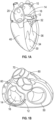
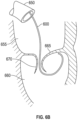
- Figs. 1A-1D the four chambers of the heart are shown, the left atrium 10, right atrium 20, left ventricle 30, and right ventricle 40.
- the mitral valve 60 is disposed between the left atrium 10 and left ventricle 30. Also shown are the tricuspid valve 50 which separates the right atrium 20 and right ventricle 40, the aortic valve 80, and the pulmonary valve 70.
- the mitral valve 60 is composed of two leaflets, the anterior leaflet 12 and posterior leaflet 14. In a healthy heart, the edges of the two leaflets oppose during systole at the coaptation zone 16.
- the fibrous annulus 120 provides attachment for the two leaflets of the mitral valve, referred to as the anterior leaflet 12 and the posterior leaflet 14.
- the leaflets are axially supported by attachment to the chordae tendinae 32.
- the chordae attach to one or both of the papillary muscles 34, 36 of the left ventricle.
- the chordae support structures tether the mitral valve leaflets, allowing the leaflets to open easily during diastole but to resist the high pressure developed during ventricular systole.
- the shape and tissue consistency of the leaflets helps promote an effective seal or coaptation.
- the leading edges of the anterior and posterior leaflet come together along the zone of coaptation 16, with a lateral cross-section 160 of the three-dimensional coaptation zone (CZ) being shown schematically in Fig. 1E .
- the anterior and posterior mitral leaflets are dissimilarly shaped.
- the anterior leaflet is more firmly attached to the annulus overlying the central fibrous body (cardiac skeleton), and is somewhat stiffer than the posterior leaflet, which is attached to the more mobile posterior mitral annulus.
- Approximately 80 percent of the closing area is the anterior leaflet.
- the fibrous trigones 124, 126 form the septal and lateral extents of the central fibrous body 128.
- the fibrous trigones 124, 126 may have an advantage, in some embodiments, as providing a firm zone for stable engagement with one or more annular or atrial anchors.
- the coaptation zone CL between the leaflets 12, 14 is not a simple line, but rather a curved funnel-shaped surface interface.
- the first 110 (lateral or left) and second 114 (septal or right) commissures are where the anterior leaflet 12 meets the posterior leaflet 14 at the annulus 120. As seen most clearly in the axial views from the atrium of Fig.
- an axial cross-section of the coaptation zone generally shows the curved line CL that is separated from a centroid of the annulus CA as well as from the opening through the valve during diastole CO.
- the leaflet edges are scalloped, more so for the posterior versus the anterior leaflet. Malcoaptation can occur between one or more of these A-P (anterior-posterior) segment pairs A1/P1, A2/P2, and A3/P3, so that mal-coaptation characteristics may vary along the curve of the coaptation zone CL.
- a properly functioning mitral valve 60 of a heart is open during diastole to allow blood to flow along a flow path FP from the left atrium toward the left ventricle 30 and thereby fill the left ventricle.
- the functioning mitral valve 60 closes and effectively seals the left ventricle 30 from the left atrium 10 during systole, first passively then actively by increase in ventricular pressure, thereby allowing contraction of the heart tissue surrounding the left ventricle to advance blood throughout the vasculature.
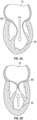
- Fig. 3A-3B and 4A-4B there are several conditions or disease states in which the leaflet edges of the mitral valve fail to oppose sufficiently and thereby allow blood to regurgitate in systole from the ventricle into the atrium. Regardless of the specific etiology of a particular patient, failure of the leaflets to seal during ventricular systole is known as mal-coaptation and gives rise to mitral regurgitation.
- mal-coaptation can result from either excessive tethering by the support structures of one or both leaflets, or from excessive stretching or tearing of the support structures.
- Other, less common causes include infection of the heart valve, congenital abnormalities, and trauma.
- Valve malfunction can result from the chordae tendinae becoming stretched, known as mitral valve prolapse, and in some cases tearing of the chordae 215 or papillary muscle, known as a flail leaflet 220, as shown in Fig. 3A .
- the leaflet tissue itself the valves may prolapse so that the level of coaptation occurs higher into the atrium, opening the valve higher in the atrium during ventricular systole 230. Either one of the leaflets can undergo prolapse or become flail. This condition is sometimes known as degenerative mitral valve regurgitation.
- annular dilation 240 Such functional mitral regurgitation generally results from heart muscle failure and concomitant ventricular dilation. And the excessive volume load resulting from functional mitral regurgitation can itself exacerbate heart failure, ventricular and annular dilation, thus worsening mitral regurgitation.
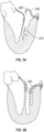
- Fig. 4A-4B illustrate the backflow BF of blood during systole in functional mitral valve regurgitation ( Fig. 4A ) and degenerative mitral valve regurgitation ( Fig. 4B ).
- the increased size of the annulus in Fig. 4A coupled with increased tethering due to hypertrophy of the ventricle 320 and papillary muscle 330, prevents the anterior leaflet 312 and posterior leaflet 314 from opposing, thereby preventing coaptation.
- the tearing of the chordae 215 causes prolapse of the posterior leaflet 344 upward into the left atrium, which prevents opposition against the anterior leaflet 342. In either situation, the result is backflow of blood into the atrium, which decreases the effectiveness of left ventricle compression.
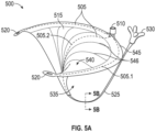
- Fig. 5A illustrates an embodiment of a coaptation assistance device 500.
- the coaptation assistance device 500 can include a coaptation assistance body 515.
- the coaptation assist body 515 can include a first coaptation surface 535.
- the first coaptation surface 535 can be disposed toward a mal-coapting native leaflet, in the instance of a mitral valve, the posterior leaflet when implanted.
- the coaptation assist body 515 can include a second coaptation surface 540.
- the second coaptation surface 540 can be opposed to the first coaptation surface 535 as shown in Fig. 5A .
- the second coaptation surface 540 can be disposed toward a mal-coapting native leaflet, in the instance of a mitral valve, the anterior leaflet when implanted.
- the first coaptation surface 535 and the second coaptation surface 540 can be bounded by a first lateral edge and a second lateral edge.
- the first coaptation surface 535 and the second coaptation surface 540 can be bounded by an inferior edge and a superior edge 545.
- the first coaptation surface 535 and the second coaptation surface 540 are two sides of the same implant structure forming the coaptation assistance body 515.
- the shape of the coaptation assistance body 515 may be characterized generally, in some embodiments, by the shape of the superior edge 545, the shape of the first coaptation surface 535, and the second coaptation surface 540.
- the coaptation assistance device 500 can include a ventricular projection 525 as shown in Fig. 5A .
- the ventricular projection 525 can extend from the inferior edge of the coaptation assistance body 515.
- the ventricular projection 525 can be placed within the left ventricle when implanted.
- the ventricular projection 525 can provide an anchoring mechanism.
- the distal end 530 of the ventricular projection 525 generally provides the anchoring mechanism.
- the distal end 530 of the ventricular projection 525 may have different shapes as shown in Fig. 5C.
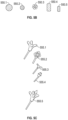
- Fig. 5C shows five embodiments of the distal end 530. It is noted that more variations are possible and they are not limited to the five embodiments shown in Fig. 5C .
- there are two types of anchors. Examples of passive anchors are shown in embodiments 555.1 through 555.4 in Fig. 5C . Passive anchors rely on entrapment behind and/or interference with the chordae. With respect to the passive anchors, in some embodiments, the largest dimension or the dimension responsible for entanglement (usually the width) with the chordae may range from 10mm to 40mm, such as 25mm.
- Distal end 555.1 includes one or more prongs.
- the prongs can be an elongate rod which extends from a central hub as shown. In the illustrated embodiment, four prongs extend from the central hub. In other embodiments, one or more prongs extend from the central hub. The prongs can extend at an angle from the central hub, thereby increasing the surface area of the distal end 530.
- Distal end 555.2 can be generally rectangular, rectangular, generally square, square, generally diamond shaped or diamond shaped.
- the distal end 555.2 can include one or more cut outs. The cut outs can increase the ability to grip tissue. In the illustrated embodiment, four cutouts are formed in the distal end. In other embodiments, one or more cut outs are provided.
- Distal end 555.3 includes one or more prongs.
- the prongs can be an elongate rod which extends from a central hub as shown. In the illustrated embodiment, two prongs extend from the central hub. In other embodiments, one or more prongs extend from the central hub. The prongs can extend at a right angle from the central hub, thereby increasing the surface area of the distal end 530.
- Distal end 555.4 includes one or more barbs.
- the barbs can extends from a central hub as shown.
- the barbs can extend back toward the central hub.
- three or more barbs extend from the central hub.
- one or more barbs in one or more directions are provided.
- Distal end 555.5 includes one or more prongs, and is similar to the configuration shown as distal end 555.1.
- Distal end 555.5 is an example of an active anchor.
- Active anchors may have features such as sharp points, barbs, or screws that may couple to the ventricular tissue. Active anchors may require a driving force, such as a torque, to embed within the tissue.
- Either passive or active anchors may be made of implant grade biocompatible materials such as silicone, PEEK, pebax, polyurethane.
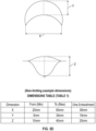
- the size of the coaptation assistance device 500 is described in detail in Fig. 5D .
- This figure shows the top view and front view of the coaptation assistance body 515 of the coaptation assistance device 500.
- the three parameters "x", "y” and “z” shown in the figure characterize the coaptation assistance device 500. Non-limiting examples of ranges and magnitudes of these variables x, y, and z are shown in the "Dimension Table" in the figure.
- the coaptation assistance device 500 can include a support structure 505.
- the support structure 505 can be referred to as a spine.
- the support structure 505 can define, at least in part, the shape of the coaptation assistance device 500.
- the support structure 505 is shown by dotted lines.
- the support structure 505 is made of a shape memory material such as but not limited to nitinol (NiTi), polyether ether ketone (PEEK) or other stiff polymer or fatigue resistant metal.
- NiTi nitinol
- PEEK polyether ether ketone
- shape memory materials enables advantages described herein.
- one advantage of a shape memory material is that its superelastic properties helps the coaptation assistance device 500 maintain its shape and functionality as a coaptation assistance device as the heart contracts and dilates and exerts pressure on the coaptation assistance device 500.
- Another example of an advantage is that a shape memory material lends itself to percutaneous delivery methods which will be described herein.
- the support structure 505 includes two sections. In some embodiments, the support structure 505 includes three or more sections. In some embodiments, one or more sections of the support structure 505 can include one or more subsection. In the embodiment shown in Fig. 5A , the support structure 505 includes two sections: a first section 505.2 and a second section 505.1.
- the first section 505.2 can extend through at least a portion of the coaptation assistance device 500 between the superior edge 545 and the ventricular projection 525. In some embodiments, the first section 505.2 can extend through the entire length between of the coaptation assistance device 500 between the superior edge 545 and the ventricular projection 525. In some embodiments, the first section 505.2 extends from a location between the superior edge 545 and the inferior edge of the coaptation assistance body 515. In some embodiments, the first section 505.2 extends from a location between the inferior edge of the coaptation assistance body 515 and the ventricular projection 525. In some embodiment, the first section 505.2 extends along the coaptation assistance body 515 and continues on to support the ventricular projection 525.
- the second section 505.1 extends through at least a portion of the coaptation assist body 515 between the first lateral edge and the second lateral edge. In some embodiments, the second section 505.1 can extend through the entire length between of the first lateral edge and the second lateral edge. In some embodiments, the second section 505.1 extends from a location between the superior edge 545 and the inferior edge of the coaptation assistance body 515. In some embodiments, the second section 505.1 extends from a location closer to the superior edge 545 than the inferior edge of the coaptation assistance body 515. In some embodiments, the second section 505.1 extends from the first lateral edge toward the second lateral edge. In some embodiments, the second section 505.1 extends from the second lateral edge toward the first lateral edge. In some embodiments, the second section 505.1 extends along a section between the first lateral edge and the second lateral edge. In some embodiments, the second section 505.1 extends along the edge of the coaptation assistance device 500.
- first section 505.2 and the second section 505.1 of the support structure 505 may be one integral piece or unitary structure. In some embodiments, the first section 505.2 and the second section 505.1 of the support structure 505 are separate components. In some embodiments, the first section 505.2 and the second section 505.1 may be two separate sections joined together by methods such as but not limited to crimping and laser welding.
- the first section 505.2 is integrated within the coaptation assistance body 515 as described herein. In some embodiments, the first section 505.2 is integrated within the ventricular projection 525 as described herein. In the invention, the second section 505.1 is integrated within the coaptation assistance body 515 as described herein. In some embodiments, the first section 505.2 can have a first zone that is generally oriented substantially parallel to a longitudinal axis of the body 515, and a second zone that is generally oriented substantially perpendicular to the longitudinal axis of the body 515 as illustrated.
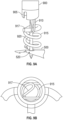
- the support structure 505 that supports the shape of the ventricular projection 525 may have various cross sections as shown by section AA in Fig. 5A and illustrated in detail in Fig. 5B .
- Fig. 5B five embodiments of the cross-section are shown; however, it is noted that the embodiments of the cross section of the support structure 505 are not limited to these five.
- Cross-section 550.1 is circular or generally circular.
- Cross-section 505.2 is circular or generally circular.
- Cross-section 550.1 can have a larger cross-sectional area than cross-section 550.2.
- Cross-section 550.3 comprises a plurality of circular or generally circular cross-sections. In the illustrated embodiment, seven circular or generally circular cross-sections collectively form the cross-section 550.3.
- cross-section 550.3 can be in the form of a cable.
- Cross-section 550.4 is rectangular or generally rectangular.
- Cross-section 550.5 is rectangular or generally rectangular.
- Cross-section 550.4 can have a larger cross-sectional area than cross-section 550.5.
- first section 505.2 and the second section 505.1 may have different cross-sections as well.
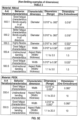
- Each cross-section or embodiment shown in Fig. 5B may have certain advantages such as some cross sections may bend easily in one direction and not in another. Some other cross sections may have higher reliability properties than others.
- the characteristics of each type of cross-section is described along with the ranges and non-limiting possible dimensions of the cross section in Table 2 in Fig. 5E for two different materials nitinol and PEEK. Although various configurations are presented in Table 2, in some embodiments, cross-sections 550.4 and 550.5 can be utilized for both materials.
- the coaptation assistance device 500 When the coaptation assistance device 500 is placed within the heart, the coaptation assistance device 500 is such that, in some embodiments, the ventricular projection 525 will generally be placed within the left ventricle as shown in Figure 5G .
- the ventricular projection 525 provides a mechanism to anchor the coaptation assistance device 500 using the structure of the ventricles.
- An example of positioning of the coaptation assistance device 500 over the posterior leaflet is illustrated in Fig. 5G .
- the coaptation assistance device 500 is illustrated with a ventricular projection 525 that has a curved shape.
- the ventricular projection 525 and/or the first support 505.2 may be composed of shape memory materials, in which case the curved shape is retained after implantation.
- the curved shape may enable the coaptation assistance device 500 to stay in position as engages to the native posterior leaflet 14.
- Fig. 5F shows an embodiment of a passive anchor for the ventricular projection 525.
- a tube 560 running along the length of the ventricular projection 525 terminates in two tubes 565.1 and 565.2, at the distal end of the coaptation assistance device 500.
- the coaptation assistance device 500 may be delivered to the left side of the heart with straightening wires such that the two tubes 565.1 and 565.2 are approximately straight as shown by the dotted lines 565.1 and 565.2 (Position A) indicating that the straightening wires are in an advanced state.
- the two tubes 565.1 and 565.2 may be made of shape memory material including but not limited to polyurethane, silicone, polyethylene, pebax and nylon. Without the straightening wires, the two tubes 565.1 and 565.2 may have a default shape that may be curled or coiled as shown by the solid lines 565.1 and 565.2 (Position B) in Fig. 5F .
- the straightening wires may be withdrawn allowing the two tubes 565.1 and 565.2 to assume their default shape (Position B).
- the two tubes 565.1 and 565.2 may provide anchoring support due to entanglement with the chordae.
- the advantage of this type of anchoring is that the straightening wires may be advanced back into the two tubes 565.1 and 565.2, straightening out the two tubes 565.1 and 565.2 and causing the two tubes 565.1 and 565.2 to disentangle from the chordae structure should it become necessary to reposition the coaptation assistance device 500 due to unsatisfactory placement.
- the example above describes two tubes 565.1 and 565.2, it will be understood that there may be one, two, or more tubes.
- FIG. 5H Yet another embodiment of anchoring the coaptation assistance device 500 is illustrated in Fig. 5H .
- An active anchor may be coupled to the distal end of the ventricular projection 525. After delivery of the implant, the active anchor may be driven through the posterior leaflet to couple to the coaptation assistance device 500 at the annular (atrial) section as shown. Methods to position and drive the anchors will be discussed herein.
- the tips of the ventricular projection 525 may be radiopaque or echogenic to aid in placement and anchoring of the coaptation assistance device 500 while the coaptation assistance device 500 is being placed percutaneously.
- fluoroscopic or ultrasound imaging modalities may be used to visualize the heart and the coaptation assistance device 500.
- the coaptation assistance device 500 includes an annular hub 510.
- the annular hub 510 can have one or more purposes. One purpose can be to serve as an anchoring device as discussed herein. Another purpose can be to provide a mechanism to deliver the coaptation assistance device 500 percutaneously as discussed herein.
- a hub (not shown) may be present at the distal end of the coaptation assistance device 500.
- the hub can be located at the end of the ventricular projection 525.
- the ventricular hub may be placed at the very distal tip of the distal end 530 of the ventricular projection 525.
- the hub 510 on the proximal side will be called the "annular hub”.
- the hub at the distal tip of the ventricular projection will specifically be called the "ventricular hub”.
- the coaptation assistance body 515 of the coaptation assistance device 500 may be made of various biocompatible materials such as expanded polytetrafluoroethylene (ePTFE). This material provides the coaptation surface against which the anterior leaflet will close.
- ePTFE expanded polytetrafluoroethylene
- the coaptation assistance body 515 of the coaptation assistance device 500 can be coupled to the support structure 505 such that the shape of the support structure 505 gives the general shape of the coaptation assistance device 500.
- the shape of the coaptation assistance device 500 may be further supported by one or more ribs 546 (not shown). There may be one, two, or more ribs 546.
- the ribs 546 may be made of various materials such as but not limited to suture, polypropylene, nylon, NiTi cable, NiTi wire and PEEK. The process of coupling the coaptation assistance body 515 of the coaptation assistance device 500 to the support structure 505 and/or the ribs 546 (if ribs 546 are present) is described herein.
- the process may commence by slipping polyethylene (PE) tubes on the support structure 505 and/or the ribs 546 (if ribs 546 are present). This combination is placed between two ePTFE sheets after which heat and pressure are applied.
- the PE tube material may melt into microholes in the support structure 505 and/or the ribs 546 when heat and compression are applied.
- the microholes in the support structure 505 and/or the ribs 546 may be deliberately placed to improve the bonding.
- PE sheets may be placed where no PE tubes may be present.
- a similar process of heat and compression is applied and a more uniform composite structure may be generated.
- the support structure 505 and/or the ribs 546 may have features such as microholes that couple the ePTFE membrane.
- the micro-hole diameters may be in the range of 0.0127cm to 0.08cm (0.005" to 0.030"), for example.
- coaptation assistance body 515 of the coaptation assistance device 500 other materials such as but not limited to sponge material, polyurethane, silicone, bovine or porcine pericardium may be utilized. Bonding processes may include but may not be limited to heat bonding, suturing and gluing.
- the coaptation assistance device 500 has perforations or slots 520. There may be one or multiple such perforations or slots 520. These perforations 520 can serve the purpose of providing sites where anchors may be placed as discussed herein.
- the coaptation assistance device 500 may be folded into a smaller structure.
- the coaptation assistance device 500 can be delivered percutaneously through a delivery catheter.
- the support structure 505 is made of a shape memory material. When the coaptation assistance device 500 is unfolded inside the heart, the desired shape of the coaptation assistance device 500 is regained.
- the first support has a first configuration wherein the first support 505.2 is generally linear and a second configuration wherein the first support 505.2 is curved.
- the first support 505.2 and the second support 505.1 are configured to permit percutaneous insertion of the coaptation assistance device 500.
- the first few steps in the delivery procedure can be similar to those that are known in the art.
- the body of the patient is punctured for example in the lower torso/upper thigh area (groin) to get access to the femoral vein.
- a trans-septal sheath and needle are inserted into the inferior vena cava and advanced up to the atrial septum, at which point a trans-septal puncture is performed and the trans-septal sheath is advanced into the left atrium.
- the needle is removed and the trans-septal sheath now provides access to the left atrium. More details about the above steps may be found in publicly available medical literature.
- the method can include various steps including those that are now described.
- the ventricular projection 525 of the coaptation assistance device 500 can be generally be placed within the left ventricle. It may be advantageous to guide the coaptation assistance device 500 to this location using various guiding techniques. For example a simple guidewire may be placed inside the trans-septal sheath and guided into the left ventricle by first entering the left atrium and going through the mitral valve. However, simple guidewire may not provide sufficient accuracy in placement of the ventricular projection 525.
- a method of placing a guidewire inside a steerable sheath may be used.
- the steerable sheath with a guidewire may be advanced through the trans-septal sheath and subsequently advanced through the mitral valve into the left ventricle where the steering ability of the steerable sheath would give additional support to position the guidewire appropriately.
- the steerable sheath requires to be removed prior to delivery of the coaptation assistance device.
- This method although providing a more accurate positioning of the guidewire, involves an extra step of removing the steerable sheath. To improve on this process in terms of reducing the number of steps needed to perform the implantation, a various embodiments of a steerable sheath are disclosed herein.
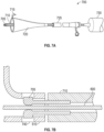
- a small diameter steerable catheter 600 is illustrated.
- the diameter 615 of a handle 610 of the steerable catheter 600 can be equal or substantially equal to the diameter 620 of the body 605 of the steerable catheter 600.
- the steerable catheter 600 can have within it a pullwire 625.
- the handle 610 is rotated, for example in the direction of the arrow 632, the distal portion of the steerable catheter 600 moves along arrow 635 from the linear position 630 to the curved position 640.
- the curved position 640 may be beneficial to position the ventricular projection 625 as discussed herein.
- the distal portion of the steerable catheter 600 moves along from the curved position 640 to the linear position 630.
- the linear position 630 of the steerable catheter 600 is shown by dotted lines, not to be confused with the pullwire 625 which is also shown in dotted lines.
- the linear position 630 may be beneficial for insertion or retraction of the steerable catheter 600 from the anatomy.
- the diameter of the handle 610 can be equal to the diameter of the body 605. This can be advantageous as the coaptation assistance device 500 may slide over the handle 610 and/or the body 605 smoothly after the steerable catheter 600 is placed in the ventricle.
- the steerable catheter 600 can include an extension 612 at the proximal end which extends from the handle 610.
- the extension 612 can be a wire or other elongate structure. The purpose of the extension 612 is to aid in the loading of other catheters or devices while allowing a physician or other operators to retain control of the steerable catheter 600. Subsequent to loading of the other catheters or devices on the extension 612, the steerable catheter 600 is utilized to guide the other catheters or devices.
- the length of the extension 612 can match or exceed the length of the catheter or device that is being loaded such that during the process of loading and delivering the other catheter or device, control of the steerable catheter 600 is retained.
- the extension 612 may be coupled to the handle 610 only when necessary. For example if during a procedure, the medical team decides that a longer catheter is necessary, the extension 612 may be coupled to the handle 610. Coupling mechanisms may include but are not limited to a threaded junction, a compression fit, or other mechanisms.
- Non-limiting examples of dimensions of the various subcomponents in some embodiments can be as follows: the diameter 620 of the body 605 may range from 2 to 10 Fr, such as 4 Fr, between about 2 Fr and about 6 Fr, between about 3 Fr and about 5 Fr, or less than 10 Fr, 9 Fr, 8 Fr, 7 Fr, 6 Fr, 5 Fr, 4 Fr, 3 Fr, or 2 Fr (wherein 1Fr equals 0.33mm).
- the handle 610 length may range in some cases from about 1,27cm to 5.08cm (1 ⁇ 2" to about 2"), such as about 2.54cm (1"), the handle linear travel (for pullwire activation) may range in some cases from about 0.375cm to about 7,62cm (1/8" to about 3"), such as about 0.635cm (1 ⁇ 4").
- the steerable catheter 600 may be advanced through the femoral access. Since the handle 610 is outside the patient's body, it may be rotated such that the distal portion of this steerable catheter 600 is placed in an appropriate position under the posterior leaflet.
- the extension 612 can be attached to the proximal end of the handle 610 to allow subsequent loading of the coaptation assistance device 500 and delivery catheter 700 prior to insertion into the trans-septal sheath 650, described herein.
- This delivery catheter 700 may then be used as a guide for introducing the coaptation assistance device 500 as will be explained herein.
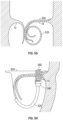
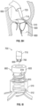
- Fig. 6B illustrates the placement of the steerable catheter 600 in the heart.
- An embodiment of the trans-septal sheath 650 is shown.
- the left atrium 655, left ventricle 660, the posterior leaflet 665 of the mitral valve and the anterior leaflet 670 of the mitral valve are also shown.
- the steerable catheter 600 is shown going through the mitral valve and being positioned under the posterior leaflet 665. It may be now appreciated how having the ability to deflect the distal potion of steerable catheter 600 can be advantageous so that an appropriate position of the coaptation assistance device 500 may be achieved.
- the distal portion of the steerable catheter 600 is able to curve under the posterior leaflet 665 as shown.
- the next general step after placing the steerable catheter 600 is to deliver the coaptation assistance device 500 to the heart. Further embodiments are now described with regards to methods and devices to achieve delivery.
- the function of the delivery catheter 700 is to carry the coaptation assistance device 500 to the heart.
- the shaft body 710 of the delivery catheter 700 can be torqueable and deflectable.
- the shaft body 710 is shown by the cross hatched lines.
- the delivery catheter 700 can include a handle 730.
- the handle 730 can have rotation mechanisms, for example pull wires etc. The rotation mechanism can deflect and steer the shaft body 710.
- Distal to the handle 730 is an implant sheath 725 which as explained herein may carry the coaptation assistance device 500 to the heart.
- a tear away funnel 720 is a tear away funnel 720.
- the tear away funnel 720 can facilitate the folding of the coaptation assistance device 500.
- the most distal end of the shaft body 710 has features that may lock the shaft body 710 to the coaptation assistance device 500 so that the coaptation assistance device 500 may be transported to the heart and placed appropriately. The locking process and features are now described in relation to Figs. 7B , 7C and 7D .
- the delivery catheter 700 and the coaptation assistance device 500 can have matching features that enable them to be locked temporarily.
- the delivery catheter 700 includes one or more distal locking tabs 705.
- the coaptation assistance device 500 can include the annular hub 510 as described herein.
- the distal locking tabs 705 of the delivery catheter 700 may couple with features in the annular hub 510 of the coaptation assistance device 500 as will be explained herein.
- the steerable catheter 600 or other guiding wires or catheters may be advanced through the ventricular projection 525 and/or anchoring mechanism 530.
- the anchoring mechanism 530 can have a hole or passageway in the center to allow the steerable catheter 600 to pass through, as shown in Fig. 7D .
- the steerable catheter 600 can pass from the anchoring mechanism 530 to the annular hub 510.
- Other paths through the coaptation assistance device 500 are contemplated.
- the steerable catheter 600 can pass from the anchoring mechanism 530 to the annular hub 510 and further to the delivery catheter 700.
- a guidewire or a catheter such as steerable catheter 600 can be inserted into the annular hub 510 and between the distal locking tabs 705, and the distal locking tabs 705 can be pushed out against the annular hub 510.
- the annular hub 510 is designed with matching pockets 740 such that the distal locking tabs 705 fit into these pockets 740.
- the annular hub 510 can include a cross-pin 745.
- the cross-pin 745 can be a solid piece that goes across the annular hub 510 and is held in place by methods that are known in the art.
- the delivery catheter 700 can include a loop of wire or suture 750.
- the suture 750 which may loop around an object such as a guidewire or the steerable catheter 600 within the annular hub 510.
- the suture 750 may extend into the handle 730 of the delivery catheter 700.
- the handle 730 may have a mechanism which controls the tension of the suture 750.
- the coaptation assistance device 500 can be pulled against and held securely to the distal end of the delivery catheter 700.
- the loop 755 of the suture 750 can slip over the cross-pin 745, thereby releasing the cross-pin 745 and the coaptation assistance device 500.
- Figs. 8A-8D show a method of delivery.
- the implant sheath 725 and the funnel 720 are advanced over the coaptation assistance device 500.
- the implant sheath 725 and the funnel 720 can be advanced over the coaptation assistance device 500 after the delivery catheter 700 is locked with the coaptation assistance device 500.
- the shape of the funnel 720 aids in the coaptation assistance device 500 closing or folding in on itself.
- the advancement of the implant sheath 725 and the funnel 720 is shown in Figs. 8A and 8B .
- the arrow 760 in Fig. 8A indicates how the coaptation assistance device 500 is pulled into the funnel 720. Once the coaptation assistance device 500 is within the implant sheath 725, the funnel 720 is removed.
- the funnel 720 is removed by pulling on a tab 715, thereby splitting the funnel 720, shown in Fig. 8C .
- the funnel 720 and the tab 715 can be then discarded.
- the implant sheath 725 containing the coaptation assistance device 500 can be advanced over the guidewire or the steerable catheter 600.
- the advantage of the design of the steerable catheter 600 becomes evident as the coaptation assistance device 500 can glide smoothly over the steerable catheter without having any difficulty due to different size diameters of the handle 610 and the body 605.
- the implant sheath 725 can be inserted into the trans-septal sheath 650 as shown Fig. 8D .
- the system of the coaptation assistance device 500 and the implant sheath 725 is advanced until it exits the trans-septal sheath 650 as shown in Fig. 8E .
- the delivery catheter 700 is deflected such that the implant sheath 725 is positioned between the leaflets of the mitral valve, which is shown in Fig. 8E .
- the implant sheath 725 is placed between the chordae 765 ("P2" location). Once the implant sheath 725 attains this position, the delivery catheter 700 is held in place and the implant sheath 725 is retracted slowly, causing the coaptation assistance device 500 to start exiting the implant sheath 725 as illustrated in Fig. 8F .
- the steerable catheter 600 or an equivalent guide wire is still in place under the posterior leaflet and can still be actively adjusted or deflected using the control handle 610.
- the coaptation assistance device 500 is pushed out, following the path of the steerable catheter 600 until the distal end 530 of the ventricular projection 525 is coupled to the ventricular tissue. This is illustrated in Fig. 8G . While the coaptation assistance device 500 is being pushed out, the implant sheath 725 can be retracted. In some methods, rotational adjustments may be made to the delivery catheter 700 to ensure appropriate placement.
- the method can include the step of anchoring the coaptation assistance device 500 on the atrial aspect of the mitral valve namely, on the on the mitral valve annulus.
- a support structure 505 made of a shape memory material can be advantageous. As the coaptation assistance device 500 opens, the coaptation assistance device 500 assumes the shape that was intended due to the action of the shape memory material.
- the shape of the coaptation assistance device 500 as described herein, can be intended to provide a new coaptation surface so that regurgitant flows are reduced or eliminated.
- the delivery catheter 700 which can be still coupled to the annular hub 510 of the coaptation assistance device 500, may now be manipulated (rotationally and axially) to position the coaptation assistance device 500 appropriately over the posterior leaflet of the native valve.
- the support structure 505 of the coaptation assistance device 500 may have features which may attach to the tissue.
- these features are passive hooks. In some methods, these features engage the annulus such that the coaptation assistance device 500 may be held in place while anchoring is commenced.
- Fig. 8H shows the state of the delivery catheter 700 with the implant sheath 725 retracted and the shaft body 710 still coupled to the annular hub 510.
- the anchor 800 may be coupled to the delivery catheter 700 and/or the coaptation assistance device 500 in various ways.
- the annular hub 510 has a cross-pin 512.
- the cross-pin 512 provides a site about which a helical structure 815 of the anchor 800 may wrap around as shown.
- the anchor 800 can have a shoulder 805.
- the shoulder 805 may fit around the shaft body 710 of the delivery catheter 700.
- the shoulder 805 may have features such as windows 810 which can lock the distal locking tabs 705 of the delivery catheter 700.
- the distal locking tabs 705 of the delivery catheter 700 can lock when a pin, guidewire or a catheter such as the steerable catheter 600 is present within the shaft body 710 of delivery catheter 700.
- the anchor 800 can be preloaded onto the coaptation assistance device 500 and locked in place with the delivery catheter 700 during the process of mounting the coaptation assistance device 500 onto the delivery catheter 700. This can occur prior to when the coaptation assistance device 500 is pulled into the implant sheath 725 and being readied for insertion into the femoral vein.
- torque can be applied to the shaft body 710 such that the anchor 800 is driven into the tissue.
- fluoroscopic markers may be present on the anchor 800. The markers may be located at the proximal end. These markers may inform the medical team about how far the anchor 800 may have travelled towards the annular hub 510 and may be informative about when the anchor 800 is securely in place.
- the torque level at the handle 730 may spike as the anchor 800 bottoms out on the annular hub 510. This increased torque level may be felt at the handle 730 providing feedback that appropriate torque has been applied.
- the central guidewire or the steerable catheter 600 can be retracted. This causes the distal locking tabs 705 to fall back from the windows 810 of the anchor 800, thus unlocking the delivery catheter 700 and the anchor 800. This can cause the releasing the coaptation assistance device 500.
- the delivery catheter 700 and steerable catheter 600 may now be completely retracted.
- FIG. 9A One such embodiment is shown in Fig. 9A .
- the delivery catheter 700 (not shown) has been retracted and an anchor catheter 900 has been advanced through the femoral access.
- the anchor catheter 900 is torqueable.
- One or more anchor catheters 900 can be provided.
- the distal tip of the anchor catheter 900 may have one or more features to lock the anchors in place during the delivery of the anchor.
- the distal tip has a cut-out 905 which may receive a portion of the helical anchor 915.
- the anchor catheter 900 may also have central pin 920.
- the central pin 920 can have a pointed end on the distal tip. In some embodiments, the central pin 920 can have the ability to be retracted.
- Fig. 9A shows a loop 910.
- the ends (not shown) of the loop 910 may travel to the handle of the anchor catheter 910 or some length therebetween such that the tension of the loop 910 may be controlled.
- the loop 910 go over a crossbar 917 or other portion which forms the proximal part of the helical anchor 915.
- the top view of the helical anchor 915 with the crossbar 917 is shown in Fig. 9B . While outside the body, prior to entry into the trans-septal sheath (not shown), the helical anchor 915 may be placed adjacent to the central pin 920.
- the loop 910 may be arranged in such a manner that when tension is applied to the loop 910, the loop 910 keeps the helical anchor 915, and the central pin 920 locked in place. In Fig. 9A , this arrangement is retracted so that the cutouts 905 receive the proximal portion of the helical anchor 915. Keeping the loop 910 in tension, the entire arrangement is advanced into the trans-septal sheath.
- the anchor catheter 900 is adjusted so that the distal end of the anchor catheter 900 is positioned over a commissure hole 520.
- the central pin 920 and the helical anchor 915 are advanced such that the central pin 920 first pierces the tissue after going through a commissure hole 520. Torque is applied to the anchor catheter 900 and the helical anchor 915 pierces the tissue.
- the helical anchor 915 anchors the support structure 505 or frame of the coaptation assistance device 500 to the tissue. After the helical anchor 915 is in place, the central pin 920 is retracted.
- the retraction of the central pin 920 can allows the loop 910 to slip over the crossbar 917 of the helical anchor 915, thereby releasing the anchor 915. This process can be repeated for the other commissure site to anchor both extreme projections of the coaptation assistance device 500.
- a delivery catheter 1000 may have multiple lumens 1040.
- the delivery catheter 1000 may have a cross-section as shown in Fig. 10B .
- the lumens 1040 may carry individual torqueable drive shafts. Each drive shaft can be locked onto an anchor as the case is for shafts 1020 and 1030 or onto the annular hub 510 as is shown for shaft 1010.
- Each torqueable shaft 1010, 1020, 1030 may have the design of the anchor catheter 900 illustrated in Fig. 9A .
- the delivery catheter 1000 may have a central lumen 1050 through which a guidewire or the steerable catheter 600 may pass.
- the multiple torqueable drive shafts 1010, 1020, 1030, a guidewire or the steerable catheter 600 along with the coaptation assistance device 500 can all be loaded and retracted into the implant sheath of the delivery catheter 1000 prior to entry into the trans-septal sheath.
- This entire arrangement can be advanced and the same procedure as explained herein can be followed to place the coaptation assistance device 500.
- the advantageous aspect of this arrangement is that the anchoring process may be accomplished without the need to retract the anchor catheter multiple times, reloading the anchors and reentering the body.
- Fig. 11A shows an anchor with grappling hooks.
- Fig. 11B shows an anchor that resembles an umbrella.
- the anchors may be made of a shape memory material.
- the anchors may be loaded into a delivery catheter such as the delivery catheter illustrated in Fig. 11C .
- Locking mechanisms such as those described herein may be used to lock the anchors to the delivery catheter.
- the delivery catheter may have a pointed end so that the delivery catheter may be guided to an appropriate location and initially pierce the tissue. After the delivery catheter is placed at an appropriate location and the initial piercing is accomplished, one or more of the anchors may be advanced and set in place. This step is followed by unlocking and retracting the delivery catheter.
- Fig. 11D is an illustration of how the umbrella anchor of Fig. 11B may look after it has been set into the tissue to anchor the coaptation assistance device 500. Due to the natural unstressed shape of the anchor, when deployed in the tissue over the coaptation assistance device 500, the deformed shape would have an effective spring-force on the face of the coaptation assistance device 500, ensuring a good foothold.
- the coaptation assistance device 500 described in Figs. 5A-F can include the support structure 505.
- the support structure 506 can be made of shape memory material as described herein.
- another configuration is contemplated. This configuration can be called the spineless coaptation assistance device to indicate that the support structure is removed after placement of the coaptation assistance device in the heart. Both types of coaptation assistance devices can have certain advantages.
- the spineless coaptation assistance device may be advantageous due to fewer components and materials and no possible metal fatigue.
- Fig. 12 shows an embodiment of the spineless coaptation assistance device 1200.
- the spineless coaptation assistance device 1200 can include a tube or a passageway 1210.
- the passageway 1210 can be placed around the annular edge. This passageway 1210 can be called the annular tube.
- the spineless coaptation assistance device 1200 can include a tube or passageway 1212 along the ventricular projection. This passageway 1212 can be called the ventricular tube.
- the profile of the passageway 1210 can be shown towards the ends of the annular tube. Although a circular profile is illustrated, the tubes or passageways 1210, 1212 may have other profiles including but not limited to oval and flat.
- the support structure 1210.1, 1210.2, 1210.3 is shown by dotted lines except at the annular edges where the support structures 1210.1 and 1210.3 protrude.
- the support structure 1210.1, 1210.2, 1210.3 may have three distinct sections, where 1210.1 and 1210.3 are placed in the annular tube and 1210.2 is placed in the ventricular tube.
- the support structure 1210.1, 1210.2, 1210.3 can be coupled within a spine hub 1220.
- the support structure 1210.1, 1210.2, 1210.3 may be distinct and separate sections.
- the support structure 1210.1, 1210.2, 1210.3 may be joined together by using one of various methods such as, but not limited to, crimping and laser welding.
- This arrangement of the support structure 1210.1, 1210.2, 1210.3 and the coaptation assistance device 1200 allows the support structure 1210.1, 1210.2, 1210.3 to be extracted from the coaptation assistance device 1200.
- the support structure 1210.1, 1210.2, 1210.3 is extracted by applying a pulling force on spine hub 1220. More detail about the coaptation assistance device 1200, and the procedure to deliver and anchor the coaptation assistance device 1200, will be provided herein.
- Figs. 13A and 13B illustrate the delivery procedure of the coaptation assistance device 1200.
- Fig. 13A shows the coaptation assistance device 1200 of Fig. 12 .
- Fig. 13A shows an additional feature, an anchor site 1300. This anchor site 1300 will be described in greater detail herein.
- the steerable catheter 600 can inserted into the coaptation assistance device 1200.
- the steerable catheter 600 can be inserted from the distal tip of the ventricular projection 1212.
- the steerable catheter 600 can exits from an exit aperture 1335.
- a delivery catheter 1320 can be provided.
- the delivery catheter 1320 can include a torqueable shaft 1310.
- the delivery catheter 1320 can include a hub locking feature 1330 that couples with a hub anchor 1300. In Fig. 13A , the hub locking feature 1330 is shown as a screw. Other locking mechanisms explained herein may be utilized.
- Fig. 13B illustrates more detail with regard to the delivery catheter 1320.
- the distal tip of the delivery catheter 1320 can include a funnel 1360. Proximal to the funnel 1360, an implant introducer 1340 may be present. At the very proximal end, the delivery catheter 1320 may have a handle 1370.
- the steerable catheter 600 can be threaded through the coaptation assistance device 1200 as described herein.
- the funnel 1360 can be inserted on to the distal tip of the delivery catheter 1320.
- the coaptation assistance device 1200 can be locked in place using the locking feature 1330, such that the hub anchor 1300 is connected to the torqueable shaft 1310.
- the steerable catheter 600 can be threaded through an angled side port 1350 on the implant introducer 1340.
- the coaptation assistance device 1200 and the steerable catheter 600 can be pulled through the funnel 1360 by retracting the delivery catheter 1320. With continued retraction, the coaptation assistance device 1200 will fold upon itself within the implant introducer 1340.
- the funnel 1360 is removed and discarded.
- the funnel 1360 may be designed such that it may be easily removed. Designs for the funnel include but are not limited to the peel away design (shown previously in Figs. 8A-8C ) or a clamshell design ( Fig. 13B ).
- the delivery catheter 1320 along with the implant introducer 1340 can be advanced over the steerable catheter 600 until the implant introducer 1340 couples with the hub of the trans-septal sheath 650. At this point, the implant introducer 1340 may not be able to advance further but the coaptation assistance device 1200 itself can be advanced into the trans-septal sheath.
- the next several steps are similar to that shown in Figs. 8E through 8G , except in this example, no implant sheath is used.
- the coaptation assistance device 1200 is placed over the posterior leaflet and the ventricular projection 1212 is placed in the left ventricle.
- the steerable catheter 600 can be retracted allowing the ventricular projection 1212 to curl or coil under P2.
- the hub anchor 1300 can be rotated or otherwise activated.
- the hub anchor 1300 can anchor the proximal side of the coaptation assistance device 1200 to the annulus.
- the torqueable shaft 1310 can retracted.
- the hub locking feature 1330 is retracted pulling the support structure 1210.1, 1210.2, 1210.3 along with it.
- the coaptation assistance device 1200 may now be operational in the left heart without the support structure 1210.1, 1210.2, 1210.3.
- Fig. 14A shows an embodiment for anchoring the coaptation assistance device 1200.
- the coaptation assistance device 1200 may need additional anchors.
- the coaptation assistance device 1200 may utilize closely spaced anchors.
- the coaptation assistance device 1200 may utilize additional and closely spaced anchors than a similar coaptation assistance device with a support structure 505, described herein.
- Fig. 14A shows an embodiment of anchors 1400, which may be used to couple the coaptation assistance device 1200 and the tissue.
- Fig. 14B shows another embodiment. In Fig.
- a suture or tape 1410 is used to "sew" the coaptation assistance device 1200 to the tissue.
- the suture or tape 1410 may be made of one of several materials including, but not limited to, polypropylene or nylon.
- Fig. 15A shows an embodiment of an anchor catheter 1500 that delivers multiple anchors.
- Several anchors 1510 including anchor 1510.1 and anchor 1510.2, are stacked within the anchor catheter 1500.
- Fig. 15A shows two anchors 1510.1 and 1510.2 stacked within the anchor catheter 1500, more or fewer anchors may be stacked.
- Each anchor 1510 may include a coil section 1550.
- the coil section 1550 can include a pointed end 1570.
- the anchor 1510 may include an anchor head 1560.
- the anchor head 1560 may have one of several cross sections shown by 1545.1, 1545.2, 1545.3 and 1545.4 in Fig. 15A . Other cross sections are possible.
- the anchors 1510 are loaded onto a central shaft 1520 of the anchor catheter 1500.
- the central shaft 1520 and the anchors 1510 may have a matching cross section such that the anchors 1510 may be rotationally coupled to the central shaft 1520.
- a spring 1540 can be included at the proximal end of the anchor catheter 1500. This spring 1540 provides a pushing force such that as the central shaft 1520 is rotated, the anchors 1510 exit the distal end of the anchor catheter 1500 in the direction of arrow 1550. As the anchors 1510 exit, the anchor 1510 can engage with the coaptation assistance device 1200 and the tissue to couple the coaptation assistance device 1200 to the tissue.
- the rotation of the central shaft 1520 may be controlled by an operator such as a doctor.
- the central shaft 1520 is coupled to a torqueable wire
- the torqueable wire may be controlled manually. In some embodiments, the torqueable wire may be controlled via an electric motor. Other methods to impart a rotational motion to the central shaft 1520 are contemplated.
- a feature that is not shown in the Fig. 15A is the ability to steer and position the distal end of the anchor catheter 1500. As one anchor 1510 is delivered, the distal tip may need to be repositioned to deliver the next anchor 1510. A steering mechanism such as pull wires may be included to steer the distal tip of the anchor catheter 1500.
- Fig. 15B shows another embodiment of an anchor catheter 1600 that delivers multiple anchors.
- Fig. 15B shows only the distal tip of an anchor catheter 1600.
- the anchor catheter 1600 can include multiple anchors 1610 such as 1610.1 and 1610.2. Although the anchor catheter 1600 shows five anchors, more or fewer anchors 1610 may be loaded at any one time.
- the anchor catheter 1600 may have a central shaft 1630.
- the anchor catheter 1600 can include threads such as 1620 on the inside of the housing 1605. These threads 1620 can house the coils of the anchors 1610 as shown. To initially load the anchor catheter 1600, the anchors 1610 are inserted into the housing 1605. The anchors 1610 are inserted onto the central shaft 1630.
- the cross-section of the central shaft 1630 may match the cross-section of the anchors 1610 so that the anchors 1610 may be mounted on the central shaft 1630.
- the rotation of the central shaft 1630 may be controlled by a torqueable cable (not shown) which may couple the central shaft 1630 to a handle (not shown) of the anchor catheter 1600.
- the operator such as a doctor may control the rotation.
- the torqueable wire may be controlled manually.
- the torqueable wire may be controlled via an electric motor. As the central shaft 1630 rotates, the threads will force the anchors 1610 to exit the anchor catheter 1600 and engage with the coaptation assistance device 1200 and the tissue to couple the coaptation assistance device 1200 and the tissue together.
- the anchor catheter 1600 may also have pull wires to steer the distal tip of the anchor catheter 1600 so that as one anchor 1610 is delivered, the anchor catheter 1600 may be positioned to deliver the next anchor 1610.
- Fig. 15B illustrates a central suture 1635.
- the central suture 1635 can include a ball 1640 coupled to the end of the central suture 1635.
- Figs. 15C and 15D illustrate how the central suture 1635 and ball 1640 may be used.
- the ball 1640 can sit in a pocket inside the first anchor 1610.1.
- the central suture 1635 can connect the first anchor 1610.1 to the second anchor 1610.2 and others anchors 1610 (not shown in the figure).
- This arrangement may provide the ability to use the central suture 1635 as a guide wire to return back to an anchor 1610 after the anchor 1610 has been screwed into the tissue 1645.
- the operator may wish to return to the anchor 1610 to reposition or adjust the anchor 1610.
- the central suture 1635 may provide a tether for the loose anchors 1610, therefore preventing embolic events.
- Fig. 16A-C shows another embodiment of an anchor catheter 1700 that delivers multiple anchors.
- the anchor catheter 1700 can have a hollow shaft.
- the hollow shaft can be pointed at the distal end which may be used to pierce the coaptation assistance device 1200 and tissue.
- Multiple anchors 1710 such as 1710.1, 1710.2 may be arranged within the hollow shaft of the anchor catheter 1700.
- the anchors 1710 can be hollow barrels.
- a suture 1720 may be threaded through the anchors 1710 as shown.
- the suture 1720 may be secured to the first anchor 1710.1 by arranging the suture 1720 to exit the second anchor 1710.2 and enter the first anchor 1710.1 through a side aperture 1740.
- the suture 1720 may then be secured by means of a knot as depicted in dotted lines within the first anchor 1710.1.
- the suture 1720 in the other anchors 1710, except the first anchor 1710.1, may appear as illustrated for the anchor 1710.2.
- the anchors 1710, except the first anchor 1710.1 have a portion of their walls cut out. The cut outs can aids in better trapping the anchors within the tissue, similar to a toggle-bolt.
- a feature such as a pusher tube 1750 may be present to cause the anchors 1710 such as 1710.1 and 1710.2 to exit the anchor catheter 1700 at the distal end.
- the pusher 1750 may be attached to a handle (not shown) so as to enable an operator such as a doctor to deposit one or more anchors 1710 when appropriate.
- the arrow 1760 indicates the direction of the push.
- Fig. 16B-C illustrates how the anchor catheter 1700 of Fig. 16A may operate.
- the anchor catheter 1700 is advanced through the coaptation assistance device 1200 through a slot such as described by 520 in Fig. 5A .
- the anchor catheter 1700 then pierces the tissue 1645.
- the operator pushes the first anchor 1710.1 out of the anchor catheter 1700, depositing the anchor 1710.1 within the tissue.
- the rest of the anchors 1710 are deposited as illustrated in Fig. 16C .
- the anchor catheter 1700 is pulled out of the tissue after depositing the first anchor 1710.1 in order to enter a second location.
- the anchor catheter 1700 can deposit the second anchor 1710.2. This process is continued until desired to secure the coaptation assistance device 1200 to the tissue.
- a cutter (not shown) can be advanced inside the anchor catheter 1700 to cut the suture 1720, leaving behind the anchors 1710.
- the anchors 1710 may be radio opaque or they may be covered by a radio graphic marker. During the process of delivery of the anchors 1710, the radio opaque markers may be visualized if a fluoroscope is used. This may help in spacing the anchors 1710 around the annulus of the coaptation assistance device 1200.
- the MR is assessed while securing the coaptation assistance device 1200 and the pitch and/or the location of the sewing action is determined according to the presence or absence of the MR
- Fig. 17A illustrates another embodiment of a spineless coaptation assistance device 1800.
- the support structure 1810 may only traverse down the ventricular projection 1820.
- a tube or passageway 1830 may be present around the annular edge of the coaptation assistance device 1800.
- an anchor catheter 1850 can be inserted into the tube 1830 as shown in Fig. 17B .
- the anchor catheter 1850 can be a deflectable anchor catheter.
- Fig. 17B also shows a first site 1860.1 where an anchor such as that described by 1560 in Fig. 15A can be delivered.
- an anchor such as that described by 1560 in Fig. 15A can be delivered.
- the anchors (not shown) may be delivered securing the coaptation assistance device 1800 to the tissue.
- the tip of the anchor catheter 1850 may be radio opaque which may then be visualized during the anchor delivery process. The visualization of the tip may be utilized to locate the anchors around the annulus of the coaptation assistance device 1800.
- Fig. 17B illustrates a first anchor location 1860.1
- Fig. 17C illustrates a second anchor location 1860.2.
- the anchor catheter 1850 is retracted completely as shown in Fig. 17D .
- the support structure 1810 can be removed as shown in Fig. 17E .
- the support structure 1810 may not be limited only to the ventricular projection; it may also be inserted through the annular tube 1830 such that a desired shape may be maintained.
- the support structure can be a shape memory material. Utilizing a support structure around the annular tube 1830 may result in an anchor catheter which may have relatively simpler control mechanisms compared to the anchor catheter 1850 used for the coaptation assistance device 1800 described in Fig. 17A .
Landscapes
- Health & Medical Sciences (AREA)
- Cardiology (AREA)
- Life Sciences & Earth Sciences (AREA)
- Veterinary Medicine (AREA)
- Biomedical Technology (AREA)
- Heart & Thoracic Surgery (AREA)
- Engineering & Computer Science (AREA)
- Animal Behavior & Ethology (AREA)
- General Health & Medical Sciences (AREA)
- Public Health (AREA)
- Surgery (AREA)
- Oral & Maxillofacial Surgery (AREA)
- Vascular Medicine (AREA)
- Transplantation (AREA)
- Medical Informatics (AREA)
- Nuclear Medicine, Radiotherapy & Molecular Imaging (AREA)
- Molecular Biology (AREA)
- Rheumatology (AREA)
- Prostheses (AREA)
Applications Claiming Priority (2)
| Application Number | Priority Date | Filing Date | Title |
|---|---|---|---|
| US201462014060P | 2014-06-18 | 2014-06-18 | |
| PCT/US2015/036260 WO2015195823A1 (en) | 2014-06-18 | 2015-06-17 | Mitral valve implants for the treatment of valvular regurgitation |
Publications (4)
| Publication Number | Publication Date |
|---|---|
| EP3157469A1 EP3157469A1 (en) | 2017-04-26 |
| EP3157469A4 EP3157469A4 (en) | 2018-03-14 |
| EP3157469B1 EP3157469B1 (en) | 2021-12-15 |
| EP3157469B2 true EP3157469B2 (en) | 2024-10-02 |
Family
ID=54868606
Family Applications (1)
| Application Number | Title | Priority Date | Filing Date |
|---|---|---|---|
| EP15809346.8A Active EP3157469B2 (en) | 2014-06-18 | 2015-06-17 | Mitral valve implants for the treatment of valvular regurgitation |
Country Status (6)
| Country | Link |
|---|---|
| US (3) | US10500048B2 (enExample) |
| EP (1) | EP3157469B2 (enExample) |
| JP (3) | JP6714518B2 (enExample) |
| CA (1) | CA2958061A1 (enExample) |
| ES (1) | ES2908178T5 (enExample) |
| WO (1) | WO2015195823A1 (enExample) |
Families Citing this family (177)
| Publication number | Priority date | Publication date | Assignee | Title |
|---|---|---|---|---|
| US8652202B2 (en) | 2008-08-22 | 2014-02-18 | Edwards Lifesciences Corporation | Prosthetic heart valve and delivery apparatus |
| US10517719B2 (en) | 2008-12-22 | 2019-12-31 | Valtech Cardio, Ltd. | Implantation of repair devices in the heart |
| US9968452B2 (en) | 2009-05-04 | 2018-05-15 | Valtech Cardio, Ltd. | Annuloplasty ring delivery cathethers |
| US8449599B2 (en) | 2009-12-04 | 2013-05-28 | Edwards Lifesciences Corporation | Prosthetic valve for replacing mitral valve |
| US10058323B2 (en) | 2010-01-22 | 2018-08-28 | 4 Tech Inc. | Tricuspid valve repair using tension |
| US9307980B2 (en) | 2010-01-22 | 2016-04-12 | 4Tech Inc. | Tricuspid valve repair using tension |
| US8579964B2 (en) | 2010-05-05 | 2013-11-12 | Neovasc Inc. | Transcatheter mitral valve prosthesis |
| CA3035048C (en) | 2010-12-23 | 2021-05-04 | Mark Deem | System for mitral valve repair and replacement |
| US8888843B2 (en) | 2011-01-28 | 2014-11-18 | Middle Peak Medical, Inc. | Device, system, and method for transcatheter treatment of valve regurgitation |
| US8845717B2 (en) | 2011-01-28 | 2014-09-30 | Middle Park Medical, Inc. | Coaptation enhancement implant, system, and method |
| US9308087B2 (en) | 2011-04-28 | 2016-04-12 | Neovasc Tiara Inc. | Sequentially deployed transcatheter mitral valve prosthesis |
| US9554897B2 (en) | 2011-04-28 | 2017-01-31 | Neovasc Tiara Inc. | Methods and apparatus for engaging a valve prosthesis with tissue |
| CN107496054B (zh) | 2011-06-21 | 2020-03-03 | 托尔福公司 | 人工心脏瓣膜装置及相关系统和方法 |
| EP3725269A1 (en) | 2011-06-23 | 2020-10-21 | Valtech Cardio, Ltd. | Closure element for use with annuloplasty structure |
| US9763780B2 (en) | 2011-10-19 | 2017-09-19 | Twelve, Inc. | Devices, systems and methods for heart valve replacement |
| US9655722B2 (en) | 2011-10-19 | 2017-05-23 | Twelve, Inc. | Prosthetic heart valve devices, prosthetic mitral valves and associated systems and methods |
| US10016271B2 (en) | 2011-10-19 | 2018-07-10 | Twelve, Inc. | Prosthetic heart valve devices, prosthetic mitral valves and associated systems and methods |
| JP6151705B2 (ja) | 2011-10-19 | 2017-06-21 | トゥエルヴ, インコーポレイテッド | 心臓弁置換のためのデバイス、システムおよび方法 |
| US9039757B2 (en) | 2011-10-19 | 2015-05-26 | Twelve, Inc. | Prosthetic heart valve devices, prosthetic mitral valves and associated systems and methods |
| US11202704B2 (en) | 2011-10-19 | 2021-12-21 | Twelve, Inc. | Prosthetic heart valve devices, prosthetic mitral valves and associated systems and methods |
| US9839519B2 (en) | 2012-02-29 | 2017-12-12 | Valcare, Inc. | Percutaneous annuloplasty system with anterior-posterior adjustment |
| US9579198B2 (en) | 2012-03-01 | 2017-02-28 | Twelve, Inc. | Hydraulic delivery systems for prosthetic heart valve devices and associated methods |
| US9345573B2 (en) | 2012-05-30 | 2016-05-24 | Neovasc Tiara Inc. | Methods and apparatus for loading a prosthesis onto a delivery system |
| CN105007832B (zh) | 2013-01-09 | 2018-01-23 | 4科技有限公司 | 组织锚状物设备 |
| US9439763B2 (en) | 2013-02-04 | 2016-09-13 | Edwards Lifesciences Corporation | Prosthetic valve for replacing mitral valve |
| WO2014141239A1 (en) | 2013-03-14 | 2014-09-18 | 4Tech Inc. | Stent with tether interface |
| US9572665B2 (en) | 2013-04-04 | 2017-02-21 | Neovasc Tiara Inc. | Methods and apparatus for delivering a prosthetic valve to a beating heart |
| EP2999435B1 (en) | 2013-05-20 | 2022-12-21 | Twelve, Inc. | Implantable heart valve devices, mitral valve repair devices and associated systems |
| US10166098B2 (en) | 2013-10-25 | 2019-01-01 | Middle Peak Medical, Inc. | Systems and methods for transcatheter treatment of valve regurgitation |
| US9622863B2 (en) | 2013-11-22 | 2017-04-18 | Edwards Lifesciences Corporation | Aortic insufficiency repair device and method |
| CA2958061A1 (en) | 2014-06-18 | 2015-12-23 | Middle Peak Medical, Inc. | Mitral valve implants for the treatment of valvular regurgitation |
| US10251635B2 (en) | 2014-06-24 | 2019-04-09 | Middle Peak Medical, Inc. | Systems and methods for anchoring an implant |
| US9907547B2 (en) | 2014-12-02 | 2018-03-06 | 4Tech Inc. | Off-center tissue anchors |
| CN107205817B (zh) | 2014-12-04 | 2020-04-03 | 爱德华兹生命科学公司 | 用于修复心脏瓣膜的经皮夹具 |
| EP4420635B1 (en) | 2015-05-14 | 2025-09-24 | Edwards Lifesciences Corporation | Heart valve sealing devices and delivery devices therefor |
| CN107920895B (zh) | 2015-08-21 | 2020-06-26 | 托尔福公司 | 可植入心脏瓣膜装置、二尖瓣修复装置以及相关系统和方法 |
| US9592121B1 (en) | 2015-11-06 | 2017-03-14 | Middle Peak Medical, Inc. | Device, system, and method for transcatheter treatment of valvular regurgitation |
| WO2017100927A1 (en) | 2015-12-15 | 2017-06-22 | Neovasc Tiara Inc. | Transseptal delivery system |
| US11833034B2 (en) | 2016-01-13 | 2023-12-05 | Shifamed Holdings, Llc | Prosthetic cardiac valve devices, systems, and methods |
| JP7006940B2 (ja) | 2016-01-29 | 2022-01-24 | ニオバスク ティアラ インコーポレイテッド | 流出の閉塞を回避するための人工弁 |
| US20210212825A1 (en) * | 2016-03-08 | 2021-07-15 | Dura Llc | Transcatheter valve leaflet replacement device, delivery, guiding and fixation system and method for same |
| US20210212824A1 (en) * | 2016-03-08 | 2021-07-15 | Dura Llc | Heart valve leaflet replacement devices and multi-stage, multi-lumen heart valve delivery systems and method for use |
| US11219746B2 (en) | 2016-03-21 | 2022-01-11 | Edwards Lifesciences Corporation | Multi-direction steerable handles for steering catheters |
| US10835714B2 (en) | 2016-03-21 | 2020-11-17 | Edwards Lifesciences Corporation | Multi-direction steerable handles for steering catheters |
| US10799675B2 (en) | 2016-03-21 | 2020-10-13 | Edwards Lifesciences Corporation | Cam controlled multi-direction steerable handles |
| CN116172753A (zh) | 2016-04-29 | 2023-05-30 | 美敦力瓦斯科尔勒公司 | 具有带系绳的锚定件的假体心脏瓣膜设备以及相关联的系统和方法 |
| US20200146854A1 (en) | 2016-05-16 | 2020-05-14 | Elixir Medical Corporation | Methods and devices for heart valve repair |
| US10973638B2 (en) | 2016-07-07 | 2021-04-13 | Edwards Lifesciences Corporation | Device and method for treating vascular insufficiency |
| CN107661126B (zh) | 2016-07-27 | 2021-10-12 | 沃卡尔有限公司 | 用于经皮手术的输送系统的稳定化及操作 |
| CN107913123B (zh) * | 2016-10-11 | 2021-06-29 | 沃卡尔有限公司 | 通过导管输送植入物的装置和方法 |
| US10653862B2 (en) | 2016-11-07 | 2020-05-19 | Edwards Lifesciences Corporation | Apparatus for the introduction and manipulation of multiple telescoping catheters |
| WO2018090148A1 (en) | 2016-11-21 | 2018-05-24 | Neovasc Tiara Inc. | Methods and systems for rapid retraction of a transcatheter heart valve delivery system |
| US10905554B2 (en) | 2017-01-05 | 2021-02-02 | Edwards Lifesciences Corporation | Heart valve coaptation device |
| US11419719B2 (en) | 2017-02-06 | 2022-08-23 | Mtex Cardio Ag | Methods and systems for assisting or repairing prosthetic cardiac valves |
| JP2020506007A (ja) * | 2017-02-06 | 2020-02-27 | エムテックス カーディオ アーゲー | 人工心臓弁を補助または修復するための方法およびシステム |
| US20190358034A1 (en) * | 2017-02-17 | 2019-11-28 | Mitrapex, Inc. | Artificial heart valve |
| US10478303B2 (en) | 2017-03-13 | 2019-11-19 | Polares Medical Inc. | Device, system, and method for transcatheter treatment of valvular regurgitation |
| US10653524B2 (en) * | 2017-03-13 | 2020-05-19 | Polares Medical Inc. | Device, system, and method for transcatheter treatment of valvular regurgitation |
| CN110913801B (zh) * | 2017-03-13 | 2022-04-15 | 宝来瑞斯医疗有限公司 | 用于治疗心脏的心脏瓣膜的不良对合的对合辅助元件及用于输送其的系统 |
| CN108618871A (zh) | 2017-03-17 | 2018-10-09 | 沃卡尔有限公司 | 具有多方向锚部的二尖瓣或三尖瓣修复系统 |
| CN106821548B (zh) * | 2017-04-01 | 2020-11-03 | 上海纽脉医疗科技有限公司 | 经导管人工二尖瓣成形环装置及系统 |
| US11103351B2 (en) | 2017-04-05 | 2021-08-31 | Opus Medical Therapies, LLC | Transcatheter atrial sealing skirt and related method |
| US11123187B2 (en) | 2017-04-05 | 2021-09-21 | Opus Medical Therapies, LLC | Transcatheter atrial anchors and methods of implantation |
| BR122020023074B1 (pt) | 2017-04-05 | 2022-05-17 | Opus Medical Therapies, LLC | Conjunto de âncora epicárdica para endovascularmente entregar e implementar uma âncora no espaço pericárdico, saia de vedação atrial e conjunto médico para implementar minimamente invasivamente uma válvula no coração |
| US11337685B2 (en) | 2017-04-05 | 2022-05-24 | Opus Medical Therapies, LLC | Transcatheter anchoring assembly for a mitral valve, a mitral valve, and related methods |
| US10820992B2 (en) | 2017-04-05 | 2020-11-03 | Opus Medical Therapies, LLC | Transcatheter atrial sealing skirt, anchor, and tether and methods of implantation |
| US10433961B2 (en) | 2017-04-18 | 2019-10-08 | Twelve, Inc. | Delivery systems with tethers for prosthetic heart valve devices and associated methods |
| US10702378B2 (en) | 2017-04-18 | 2020-07-07 | Twelve, Inc. | Prosthetic heart valve device and associated systems and methods |
| US10575950B2 (en) | 2017-04-18 | 2020-03-03 | Twelve, Inc. | Hydraulic systems for delivering prosthetic heart valve devices and associated methods |
| US11224511B2 (en) | 2017-04-18 | 2022-01-18 | Edwards Lifesciences Corporation | Heart valve sealing devices and delivery devices therefor |
| SG11201907076YA (en) | 2017-04-18 | 2019-08-27 | Edwards Lifesciences Corp | Heart valve sealing devices and delivery devices therefor |
| US10799312B2 (en) | 2017-04-28 | 2020-10-13 | Edwards Lifesciences Corporation | Medical device stabilizing apparatus and method of use |
| US10959846B2 (en) | 2017-05-10 | 2021-03-30 | Edwards Lifesciences Corporation | Mitral valve spacer device |
| US10792151B2 (en) | 2017-05-11 | 2020-10-06 | Twelve, Inc. | Delivery systems for delivering prosthetic heart valve devices and associated methods |
| US10646338B2 (en) | 2017-06-02 | 2020-05-12 | Twelve, Inc. | Delivery systems with telescoping capsules for deploying prosthetic heart valve devices and associated methods |
| US10709591B2 (en) | 2017-06-06 | 2020-07-14 | Twelve, Inc. | Crimping device and method for loading stents and prosthetic heart valves |
| US10729541B2 (en) | 2017-07-06 | 2020-08-04 | Twelve, Inc. | Prosthetic heart valve devices and associated systems and methods |
| US10786352B2 (en) | 2017-07-06 | 2020-09-29 | Twelve, Inc. | Prosthetic heart valve devices and associated systems and methods |
| EP3658075B1 (en) | 2017-07-24 | 2024-07-03 | Emory University | Cardiac valve leaflet enhancer devices |
| CN111263622A (zh) | 2017-08-25 | 2020-06-09 | 内奥瓦斯克迪亚拉公司 | 顺序展开的经导管二尖瓣假体 |
| EP3675773A1 (en) | 2017-08-31 | 2020-07-08 | Half Moon Medical, Inc. | Prosthetic leaflet device |
| US11051940B2 (en) | 2017-09-07 | 2021-07-06 | Edwards Lifesciences Corporation | Prosthetic spacer device for heart valve |
| US11065117B2 (en) | 2017-09-08 | 2021-07-20 | Edwards Lifesciences Corporation | Axisymmetric adjustable device for treating mitral regurgitation |
| US11040174B2 (en) | 2017-09-19 | 2021-06-22 | Edwards Lifesciences Corporation | Multi-direction steerable handles for steering catheters |
| US10231837B1 (en) | 2018-01-09 | 2019-03-19 | Edwards Lifesciences Corporation | Native valve repair devices and procedures |
| US10238493B1 (en) | 2018-01-09 | 2019-03-26 | Edwards Lifesciences Corporation | Native valve repair devices and procedures |
| US10123873B1 (en) | 2018-01-09 | 2018-11-13 | Edwards Lifesciences Corporation | Native valve repair devices and procedures |
| LT3964175T (lt) | 2018-01-09 | 2024-10-25 | Edwards Lifesciences Corporation | Įgimto vožtuvo taisymo įtaisai |
| US10076415B1 (en) | 2018-01-09 | 2018-09-18 | Edwards Lifesciences Corporation | Native valve repair devices and procedures |
| US10105222B1 (en) | 2018-01-09 | 2018-10-23 | Edwards Lifesciences Corporation | Native valve repair devices and procedures |
| US10159570B1 (en) | 2018-01-09 | 2018-12-25 | Edwards Lifesciences Corporation | Native valve repair devices and procedures |
| US10136993B1 (en) | 2018-01-09 | 2018-11-27 | Edwards Lifesciences Corporation | Native valve repair devices and procedures |
| US10245144B1 (en) | 2018-01-09 | 2019-04-02 | Edwards Lifesciences Corporation | Native valve repair devices and procedures |
| US10973639B2 (en) | 2018-01-09 | 2021-04-13 | Edwards Lifesciences Corporation | Native valve repair devices and procedures |
| US10111751B1 (en) | 2018-01-09 | 2018-10-30 | Edwards Lifesciences Corporation | Native valve repair devices and procedures |
| US11026791B2 (en) | 2018-03-20 | 2021-06-08 | Medtronic Vascular, Inc. | Flexible canopy valve repair systems and methods of use |
| US11285003B2 (en) | 2018-03-20 | 2022-03-29 | Medtronic Vascular, Inc. | Prolapse prevention device and methods of use thereof |
| WO2019195860A2 (en) | 2018-04-04 | 2019-10-10 | Vdyne, Llc | Devices and methods for anchoring transcatheter heart valve |
| US11389297B2 (en) | 2018-04-12 | 2022-07-19 | Edwards Lifesciences Corporation | Mitral valve spacer device |
| US11207181B2 (en) | 2018-04-18 | 2021-12-28 | Edwards Lifesciences Corporation | Heart valve sealing devices and delivery devices therefor |
| US12121775B2 (en) | 2018-06-27 | 2024-10-22 | Dhiren Rajagopal | Brace for preventing finger injuries |
| JP7421546B2 (ja) | 2018-08-21 | 2024-01-24 | シファメド・ホールディングス・エルエルシー | 人工心弁デバイス、システム、および方法 |
| CA3110705A1 (en) * | 2018-09-12 | 2020-03-19 | Polares Medical Inc. | Device, system, and method for transcatheter treatment of valvular regurgitation |
| US11278437B2 (en) | 2018-12-08 | 2022-03-22 | Vdyne, Inc. | Compression capable annular frames for side delivery of transcatheter heart valve replacement |
| US10595994B1 (en) | 2018-09-20 | 2020-03-24 | Vdyne, Llc | Side-delivered transcatheter heart valve replacement |
| US10321995B1 (en) | 2018-09-20 | 2019-06-18 | Vdyne, Llc | Orthogonally delivered transcatheter heart valve replacement |
| US12186187B2 (en) | 2018-09-20 | 2025-01-07 | Vdyne, Inc. | Transcatheter deliverable prosthetic heart valves and methods of delivery |
| US11071627B2 (en) | 2018-10-18 | 2021-07-27 | Vdyne, Inc. | Orthogonally delivered transcatheter heart valve frame for valve in valve prosthesis |
| US11344413B2 (en) | 2018-09-20 | 2022-05-31 | Vdyne, Inc. | Transcatheter deliverable prosthetic heart valves and methods of delivery |
| US10912644B2 (en) | 2018-10-05 | 2021-02-09 | Shifamed Holdings, Llc | Prosthetic cardiac valve devices, systems, and methods |
| US10945844B2 (en) | 2018-10-10 | 2021-03-16 | Edwards Lifesciences Corporation | Heart valve sealing devices and delivery devices therefor |
| JP7489975B2 (ja) | 2018-10-19 | 2024-05-24 | シファメド・ホールディングス・エルエルシー | 調整可能な医療デバイス |
| US11109969B2 (en) | 2018-10-22 | 2021-09-07 | Vdyne, Inc. | Guidewire delivery of transcatheter heart valve |
| AU2019374743B2 (en) | 2018-11-08 | 2022-03-03 | Neovasc Tiara Inc. | Ventricular deployment of a transcatheter mitral valve prosthesis |
| CA3118722A1 (en) | 2018-11-20 | 2020-05-28 | Edwards Lifesciences Corporation | Deployment tools and methods for delivering a device to a native heart valve |
| SG11202105286SA (en) | 2018-11-21 | 2021-06-29 | Edwards Lifesciences Corp | Heart valve sealing devices, delivery devices therefor, and retrieval devices |
| EP3884993A4 (en) * | 2018-11-23 | 2022-06-29 | Tau-PNU Medical Co., Ltd. | Device for valve regurgitation surgery and cardiac pacemaker lead fixation |
| SG11202105391SA (en) | 2018-11-29 | 2021-06-29 | Edwards Lifesciences Corp | Catheterization method and apparatus |
| US11678983B2 (en) * | 2018-12-12 | 2023-06-20 | W. L. Gore & Associates, Inc. | Implantable component with socket |
| US11253359B2 (en) | 2018-12-20 | 2022-02-22 | Vdyne, Inc. | Proximal tab for side-delivered transcatheter heart valves and methods of delivery |
| WO2020146842A1 (en) | 2019-01-10 | 2020-07-16 | Vdyne, Llc | Anchor hook for side-delivery transcatheter heart valve prosthesis |
| EP3911273B1 (en) | 2019-01-16 | 2025-01-15 | Half Moon Medical, Inc. | Implantable coaptation assist devices with sensors and associated systems |
| US11273032B2 (en) | 2019-01-26 | 2022-03-15 | Vdyne, Inc. | Collapsible inner flow control component for side-deliverable transcatheter heart valve prosthesis |
| US11185409B2 (en) | 2019-01-26 | 2021-11-30 | Vdyne, Inc. | Collapsible inner flow control component for side-delivered transcatheter heart valve prosthesis |
| JP2022520377A (ja) | 2019-02-11 | 2022-03-30 | エドワーズ ライフサイエンシーズ コーポレイション | 心臓弁封止デバイスおよびその送達デバイス |
| PL3923867T3 (pl) | 2019-02-14 | 2024-05-27 | Edwards Lifesciences Corporation | Urządzenia do uszczelniania zastawek serca i urządzenia do ich wprowadzania |
| SG11202108606PA (en) | 2019-02-25 | 2021-09-29 | Edwards Lifesciences Corp | Heart valve sealing devices |
| US20200268371A1 (en) * | 2019-02-27 | 2020-08-27 | Covidien Lp | Purse string suture device |
| CN113543750B (zh) | 2019-03-05 | 2025-10-10 | 维迪内股份有限公司 | 用于正交经导管心脏瓣膜假体的三尖瓣反流控制装置 |
| JP7430732B2 (ja) | 2019-03-08 | 2024-02-13 | ニオバスク ティアラ インコーポレイテッド | 回収可能補綴物送達システム |
| EP3937849A1 (en) | 2019-03-12 | 2022-01-19 | Half Moon Medical, Inc. | Cardiac valve repair devices with annuloplasty features and associated systems and methods |
| US11076956B2 (en) | 2019-03-14 | 2021-08-03 | Vdyne, Inc. | Proximal, distal, and anterior anchoring tabs for side-delivered transcatheter mitral valve prosthesis |
| US11173027B2 (en) | 2019-03-14 | 2021-11-16 | Vdyne, Inc. | Side-deliverable transcatheter prosthetic valves and methods for delivering and anchoring the same |
| EP4505968A3 (en) | 2019-03-19 | 2025-05-07 | Shifamed Holdings, LLC | Prosthetic cardiac valve devices, systems |
| EP3946163B1 (en) | 2019-04-01 | 2025-08-20 | Neovasc Tiara Inc. | Controllably deployable prosthetic valve |
| US11491006B2 (en) | 2019-04-10 | 2022-11-08 | Neovasc Tiara Inc. | Prosthetic valve with natural blood flow |
| WO2020214818A1 (en) * | 2019-04-16 | 2020-10-22 | Neochord, Inc. | Transverse helical cardiac anchor for minimally invasive heart valve repair |
| AU2020267390B2 (en) | 2019-05-04 | 2025-12-04 | Vdyne, Inc. | Cinch device and method for deployment of a side-delivered prosthetic heart valve in a native annulus |
| EP4729110A2 (en) | 2019-05-20 | 2026-04-22 | Neovasc Tiara Inc. | Introducer with hemostasis mechanism |
| CN113692253B (zh) | 2019-06-11 | 2024-10-29 | 沃卡尔医药有限公司 | 用于递送腱索置换系统的系统和方法 |
| IL288722B2 (en) | 2019-06-11 | 2026-02-01 | Valcare Inc | Annuloplasty ring with posterior leaflet for minimally invasive treatment |
| WO2020257643A1 (en) | 2019-06-20 | 2020-12-24 | Neovasc Tiara Inc. | Low profile prosthetic mitral valve |
| JP7584500B2 (ja) | 2019-08-20 | 2024-11-15 | ブイダイン,インコーポレイテッド | 側方送達可能な経カテーテル人工弁の送達及び回収のデバイス及び方法 |
| CN114630665B (zh) | 2019-08-26 | 2025-06-17 | 维迪内股份有限公司 | 可侧面输送的经导管假体瓣膜及其输送和锚定方法 |
| CN114727864B (zh) * | 2019-09-19 | 2025-10-17 | 美敦力公司 | 具有接合结构和多个小叶捕获夹子的瓣膜修复装置 |
| CR20210635A (es) | 2019-10-15 | 2022-05-30 | Edwards Lifesciences Corp | Dispositivos de sellado de válvulas cardíacas y dispositivos de administración de los mismos |
| KR20220103983A (ko) * | 2019-11-19 | 2022-07-25 | 엘릭서 메디컬 코포레이션 | 심장 판막 복구를 위한 방법 및 디바이스 |
| US11147671B2 (en) | 2019-12-31 | 2021-10-19 | Creative Heart Valve Solutions Llc | Methods, implants, and systems for treatment of mitral valve prolapse |
| US20210196462A1 (en) * | 2019-12-31 | 2021-07-01 | Polares Medical Inc. | Device, system, and method for transcatheter treatment of valvular regurgitation |
| US11234813B2 (en) | 2020-01-17 | 2022-02-01 | Vdyne, Inc. | Ventricular stability elements for side-deliverable prosthetic heart valves and methods of delivery |
| IL294980A (en) | 2020-01-22 | 2022-09-01 | Opus Medical Therapies Llc | Transcatheter anchor support, systems and methods of implantation |
| EP3912595B1 (en) * | 2020-05-19 | 2023-01-04 | AVVie GmbH | Implant for improving coaptation of an atrioventricular valve |
| EP4203860A4 (en) | 2020-08-31 | 2024-10-09 | Shifamed Holdings, LLC | PROSTHETIC IMPLANT DELIVERY SYSTEM |
| CN116171140A (zh) | 2020-09-01 | 2023-05-26 | 爱德华兹生命科学公司 | 医疗装置稳定系统 |
| EP4216830B1 (en) * | 2020-09-25 | 2026-01-28 | Edwards Lifesciences Innovation (Israel) Ltd. | Anchor magazines |
| CA3194445A1 (en) | 2020-10-01 | 2022-04-07 | Vivek RAJAGOPAL | Transcatheter anchor support and methods of implantation |
| EP4247302B1 (en) | 2020-11-20 | 2026-02-18 | Medtronic, Inc. | Tricuspid valve repair devices |
| JP7835754B2 (ja) | 2020-12-04 | 2026-03-25 | シファメド・ホールディングス・エルエルシー | 張り出し人工心弁送達デバイスおよびシステム |
| US11464634B2 (en) | 2020-12-16 | 2022-10-11 | Polares Medical Inc. | Device, system, and method for transcatheter treatment of valvular regurgitation with secondary anchors |
| US12201521B2 (en) | 2021-03-22 | 2025-01-21 | Shifamed Holdings, Llc | Anchor position verification for prosthetic cardiac valve devices |
| CN113143541A (zh) * | 2021-03-26 | 2021-07-23 | 启晨(上海)医疗器械有限公司 | 一种人工瓣叶装置及其使用方法 |
| US11759321B2 (en) | 2021-06-25 | 2023-09-19 | Polares Medical Inc. | Device, system, and method for transcatheter treatment of valvular regurgitation |
| WO2023069494A1 (en) * | 2021-10-20 | 2023-04-27 | Harmony Development Group, Inc. | Transcatheter ventricular papillary anchoring system and method of implanting an integrated intracardiac flow, shape, and pressure system |
| EP4193962A1 (en) | 2021-12-07 | 2023-06-14 | AVVie GmbH | Implant for improving coaptation of an atrioventricular valve |
| EP4543309A1 (en) * | 2022-06-21 | 2025-04-30 | Boston Scientific Scimed, Inc. | Devices, systems, and methods for delivering and deploying an implantable device |
| EP4601585A1 (en) | 2022-10-14 | 2025-08-20 | Vdyne, Inc. | Devices and methods for delivering a prosthetic heart valve using supra-annular support |
| CA3228597A1 (en) | 2023-02-10 | 2025-04-28 | Vesalius Cardiovascular Inc. | Apparatus and methods for the delivery of biocompatible materials |
| CN118717199B (zh) * | 2023-03-28 | 2025-09-02 | 宁波健世科技股份有限公司 | 一种锚定系统 |
| WO2024220420A1 (en) * | 2023-04-18 | 2024-10-24 | Edwards Lifesciences Corporation | Anchoring and puncturing devices for medical procedures |
| US12478474B2 (en) | 2023-05-04 | 2025-11-25 | Polares Medical Inc. | Device, system, and method with an adaptive leaflet |
| EP4676397A2 (en) * | 2023-05-12 | 2026-01-14 | Reniva, Inc. | An implantable prosthetic posterior mitral valve |
| CN118986587B (zh) * | 2023-05-19 | 2025-09-12 | 宁波健世科技股份有限公司 | 一种可导引定位的锚定系统 |
| USD1071198S1 (en) | 2023-06-28 | 2025-04-15 | Edwards Lifesciences Corporation | Cradle |
| US12433749B2 (en) | 2023-08-25 | 2025-10-07 | Emory University | Systems, devices, and methods for reducing heart valve regurgitation |
| US12036120B1 (en) | 2023-08-30 | 2024-07-16 | Vesalius Cardiovascular Inc. | Lock delivery system |
| US12514705B2 (en) | 2024-05-29 | 2026-01-06 | Vesalius Cardiovascular Inc. | Heart valve repair apparatus |
| US12396855B1 (en) | 2024-07-25 | 2025-08-26 | Nyra Medical, Inc. | Systems, devices, and methods for reducing heart valve regurgitation |
Citations (2)
| Publication number | Priority date | Publication date | Assignee | Title |
|---|---|---|---|---|
| WO2004100803A1 (en) † | 2003-05-12 | 2004-11-25 | Cardiokinetix, Inc. | A system for improving cardiac function |
| WO2012102928A1 (en) † | 2011-01-28 | 2012-08-02 | Middle Peak Medical, Inc. | Coaptation enhancement implant, system, and method |
Family Cites Families (402)
| Publication number | Priority date | Publication date | Assignee | Title |
|---|---|---|---|---|
| US3491376A (en) | 1965-10-06 | 1970-01-27 | Donald P Shiley | Heart valve with separate suturing ring sub-assembly |
| US3503079A (en) | 1967-09-05 | 1970-03-31 | Charles A Smith | Heart valve having a guided valve float |
| NL143127B (nl) | 1969-02-04 | 1974-09-16 | Rhone Poulenc Sa | Versterkingsorgaan voor een defecte hartklep. |
| US3671979A (en) | 1969-09-23 | 1972-06-27 | Univ Utah | Catheter mounted artificial heart valve for implanting in close proximity to a defective natural heart valve |
| US3874388A (en) | 1973-02-12 | 1975-04-01 | Ochsner Med Found Alton | Shunt defect closure system |
| US3898701A (en) | 1974-01-17 | 1975-08-12 | Russa Joseph | Implantable heart valve |
| US3938197A (en) | 1974-09-03 | 1976-02-17 | Simcha Milo | Central flow prosthetic cardiac valve |
| US4078268A (en) | 1975-04-24 | 1978-03-14 | St. Jude Medical, Inc. | Heart valve prosthesis |
| USRE31040E (en) | 1975-04-24 | 1982-09-28 | St. Jude Medical, Inc. | Heart valve prosthesis |
| US4011601A (en) | 1975-10-14 | 1977-03-15 | Research Corporation | Prosthetic heart valve |
| US4007743A (en) | 1975-10-20 | 1977-02-15 | American Hospital Supply Corporation | Opening mechanism for umbrella-like intravascular shunt defect closure device |
| US4491986A (en) | 1976-05-12 | 1985-01-08 | Shlomo Gabbay | Heart valve |
| US4042979A (en) | 1976-07-12 | 1977-08-23 | Angell William W | Valvuloplasty ring and prosthetic method |
| GB1603634A (en) | 1977-05-05 | 1981-11-25 | Nat Res Dev | Prosthetic valves |
| DE2742681C3 (de) | 1977-09-22 | 1980-07-31 | Dr. Eduard Fresenius, Chemisch- Pharmazeutische Industrie Kg, 6380 Bad Homburg | Prothetisches Verschlußelement zum Ersatz der Mitral- und Tricuspldalklappe im menschlichen Herzen |
| DE2815756C3 (de) | 1978-04-12 | 1982-01-28 | Ernst-Wilhelm 5303 Bornheim Müller | Prothetisches Verschlußelement zum Ersatz der Klappen im menschlichen Herzen |
| ES474582A1 (es) | 1978-10-26 | 1979-11-01 | Aranguren Duo Iker | Procedimiento para la instalacion de valvulas mitrales en sulugar anatomico, mediante anclaje de cordajes en pilar arti-ficial |
| US4275469A (en) | 1979-12-13 | 1981-06-30 | Shelhigh Inc. | Prosthetic heart valve |
| IT1129530B (it) | 1980-01-16 | 1986-06-04 | Roberto Parravicini | Protesi valvolare cardiaca |
| ATE21330T1 (de) | 1982-01-20 | 1986-08-15 | Martin Morris Black | Kuenstliche herzklappen. |
| US4488318A (en) | 1982-04-07 | 1984-12-18 | Kaster Robert L | Prosthetic heart valve |
| IT1156682B (it) | 1982-10-14 | 1987-02-04 | Pro Bio Spe Produz Biolog Spec | Valvola biologica bicuspide a basso profilo |
| AR229309A1 (es) | 1983-04-20 | 1983-07-15 | Barone Hector Daniel | Montura para valvulas cardiacas |
| GB8424582D0 (en) | 1984-09-28 | 1984-11-07 | Univ Glasgow | Heart valve prosthesis |
| US4759758A (en) | 1984-12-07 | 1988-07-26 | Shlomo Gabbay | Prosthetic heart valve |
| US4790843A (en) | 1986-06-16 | 1988-12-13 | Baxter Travenol Laboratories, Inc. | Prosthetic heart valve assembly |
| IT1218947B (it) | 1988-01-12 | 1990-04-24 | Sorin Biomedica Spa | Protesi valvolare cardiaca |
| US4960424A (en) | 1988-06-30 | 1990-10-02 | Grooters Ronald K | Method of replacing a defective atrio-ventricular valve with a total atrio-ventricular valve bioprosthesis |
| JP2710355B2 (ja) | 1988-09-20 | 1998-02-10 | 日本ゼオン株式会社 | 医用弁装置 |
| IT1224479B (it) | 1988-10-11 | 1990-10-04 | Sorin Biomedica Spa | Otturatore per protesi valvolari cardiache protesi valvolare cardiaca provvista di un tale otturatore e relativo procedimento di fabbricazione |
| US4994077A (en) | 1989-04-21 | 1991-02-19 | Dobben Richard L | Artificial heart valve for implantation in a blood vessel |
| FR2663533B1 (fr) | 1990-06-22 | 1997-10-24 | Implants Instr Ch Fab | Valve cardiaque artificielle. |
| US5131905A (en) | 1990-07-16 | 1992-07-21 | Grooters Ronald K | External cardiac assist device |
| RU1767723C (ru) | 1990-08-14 | 1995-01-27 | Кирово-Чепецкий химический комбинат | Протез клапана сердца |
| CA2441679A1 (en) | 1991-05-16 | 1992-11-26 | 3F Therapeutics, Inc. | Cardiac valve |
| US5217484A (en) | 1991-06-07 | 1993-06-08 | Marks Michael P | Retractable-wire catheter device and method |
| US5370685A (en) | 1991-07-16 | 1994-12-06 | Stanford Surgical Technologies, Inc. | Endovascular aortic valve replacement |
| US5258023A (en) | 1992-02-12 | 1993-11-02 | Reger Medical Development, Inc. | Prosthetic heart valve |
| US5332402A (en) | 1992-05-12 | 1994-07-26 | Teitelbaum George P | Percutaneously-inserted cardiac valve |
| US5733331A (en) | 1992-07-28 | 1998-03-31 | Newcor Industrial S.A. | Total mitral heterologous bioprosthesis to be used in mitral or tricuspid heat replacement |
| US5370662A (en) | 1993-06-23 | 1994-12-06 | Kevin R. Stone | Suture anchor assembly |
| US5397348A (en) | 1993-12-13 | 1995-03-14 | Carbomedics, Inc. | Mechanical heart valve with compressible stiffening ring |
| US5487760A (en) | 1994-03-08 | 1996-01-30 | Ats Medical, Inc. | Heart valve prosthesis incorporating electronic sensing, monitoring and/or pacing circuitry |
| US5522886A (en) | 1994-07-29 | 1996-06-04 | Milo; Simcha | Heart valve prostheses |
| US6217610B1 (en) | 1994-07-29 | 2001-04-17 | Edwards Lifesciences Corporation | Expandable annuloplasty ring |
| US5593435A (en) | 1994-07-29 | 1997-01-14 | Baxter International Inc. | Distensible annuloplasty ring for surgical remodelling of an atrioventricular valve and nonsurgical method for post-implantation distension thereof to accommodate patient growth |
| US5582616A (en) | 1994-08-05 | 1996-12-10 | Origin Medsystems, Inc. | Surgical helical fastener with applicator |
| US5554186A (en) | 1994-12-22 | 1996-09-10 | Baxter International Inc. | Bileaflet mechanical heart valve having cropped slot pivot configuration and method for preventing blood stagnation therein |
| US5626613A (en) | 1995-05-04 | 1997-05-06 | Arthrex, Inc. | Corkscrew suture anchor and driver |
| US5569306A (en) | 1995-06-06 | 1996-10-29 | Thal; Raymond | Knotless suture anchor assembly |
| US6007577A (en) | 1995-06-07 | 1999-12-28 | St. Jude Medical, Inc. | Prosthetic heart valve with increased valve lumen |
| WO1996040010A1 (en) | 1995-06-07 | 1996-12-19 | St. Jude Medical, Inc. | Prosthetic heart valve with increased lumen |
| US6451024B1 (en) | 1995-06-14 | 2002-09-17 | Dexterity Surgical, Inc. | Surgical method for treating urinary incontinence, and apparatus for use in same |
| US5662683A (en) | 1995-08-22 | 1997-09-02 | Ortho Helix Limited | Open helical organic tissue anchor and method of facilitating healing |
| US5662704A (en) | 1995-12-01 | 1997-09-02 | Medtronic, Inc. | Physiologic mitral valve bioprosthesis |
| DE69630235T2 (de) | 1995-12-01 | 2004-08-05 | Medtronic, Inc., Minneapolis | Anuloplastik-Prothese |
| US5716370A (en) | 1996-02-23 | 1998-02-10 | Williamson, Iv; Warren | Means for replacing a heart valve in a minimally invasive manner |
| US6162233A (en) | 1996-02-23 | 2000-12-19 | Cardiovascular Technologies, Llc | Wire fasteners for use in minimally invasive surgery and means and methods for handling those fasteners |
| US6402780B2 (en) | 1996-02-23 | 2002-06-11 | Cardiovascular Technologies, L.L.C. | Means and method of replacing a heart valve in a minimally invasive manner |
| US5855601A (en) | 1996-06-21 | 1999-01-05 | The Trustees Of Columbia University In The City Of New York | Artificial heart valve and method and device for implanting the same |
| DE19625202A1 (de) | 1996-06-24 | 1998-01-02 | Adiam Medizintechnik Gmbh & Co | Prothetische Mitral-Herzklappe |
| DE19624948A1 (de) | 1996-06-24 | 1998-01-02 | Adiam Medizintechnik Gmbh & Co | Prothetische Herzklappe |
| US7611521B2 (en) | 1996-09-13 | 2009-11-03 | Tendon Technology, Ltd. | Apparatus and methods for tendon or ligament repair |
| EP0850607A1 (en) | 1996-12-31 | 1998-07-01 | Cordis Corporation | Valve prosthesis for implantation in body channels |
| US6183411B1 (en) | 1998-09-21 | 2001-02-06 | Myocor, Inc. | External stress reduction device and method |
| US6045497A (en) | 1997-01-02 | 2000-04-04 | Myocor, Inc. | Heart wall tension reduction apparatus and method |
| US6077214A (en) | 1998-07-29 | 2000-06-20 | Myocor, Inc. | Stress reduction apparatus and method |
| US5957949A (en) | 1997-05-01 | 1999-09-28 | World Medical Manufacturing Corp. | Percutaneous placement valve stent |
| US6063114A (en) | 1997-09-04 | 2000-05-16 | Kensey Nash Corporation | Connector system for vessels, ducts, lumens or hollow organs and methods of use |
| US6332893B1 (en) | 1997-12-17 | 2001-12-25 | Myocor, Inc. | Valve to myocardium tension members device and method |
| US6176877B1 (en) | 1998-04-20 | 2001-01-23 | St. Jude Medical, Inc. | Two piece prosthetic heart valve |
| US6221104B1 (en) | 1998-05-01 | 2001-04-24 | Cor Restore, Inc. | Anterior and interior segment cardiac restoration apparatus and method |
| US6024096A (en) | 1998-05-01 | 2000-02-15 | Correstore Inc | Anterior segment ventricular restoration apparatus and method |
| US6544167B2 (en) | 1998-05-01 | 2003-04-08 | Correstore, Inc. | Ventricular restoration patch |
| US6250308B1 (en) | 1998-06-16 | 2001-06-26 | Cardiac Concepts, Inc. | Mitral valve annuloplasty ring and method of implanting |
| WO2000016701A1 (en) | 1998-09-18 | 2000-03-30 | United States Surgical Corporation | Endovascular fastener applicator |
| US7128073B1 (en) | 1998-11-06 | 2006-10-31 | Ev3 Endovascular, Inc. | Method and device for left atrial appendage occlusion |
| US6066160A (en) | 1998-11-23 | 2000-05-23 | Quickie Llc | Passive knotless suture terminator for use in minimally invasive surgery and to facilitate standard tissue securing |
| US6045573A (en) | 1999-01-21 | 2000-04-04 | Ethicon, Inc. | Suture anchor having multiple sutures |
| JP2002535632A (ja) | 1999-01-26 | 2002-10-22 | エドワーズ ライフサイエンシーズ コーポレイション | 解剖学的オリフィス寸法測定器およびオリフィス寸法測定方法 |
| US6752813B2 (en) | 1999-04-09 | 2004-06-22 | Evalve, Inc. | Methods and devices for capturing and fixing leaflets in valve repair |
| CA2620783C (en) | 1999-04-09 | 2011-04-05 | Evalve, Inc. | Methods and apparatus for cardiac valve repair |
| US7226467B2 (en) | 1999-04-09 | 2007-06-05 | Evalve, Inc. | Fixation device delivery catheter, systems and methods of use |
| US8216256B2 (en) | 1999-04-09 | 2012-07-10 | Evalve, Inc. | Detachment mechanism for implantable fixation devices |
| US6312464B1 (en) | 1999-04-28 | 2001-11-06 | NAVIA JOSé L. | Method of implanting a stentless cardiac valve prosthesis |
| US6296662B1 (en) | 1999-05-26 | 2001-10-02 | Sulzer Carbiomedics Inc. | Bioprosthetic heart valve with balanced stent post deflection |
| US6287339B1 (en) | 1999-05-27 | 2001-09-11 | Sulzer Carbomedics Inc. | Sutureless heart valve prosthesis |
| US6602289B1 (en) | 1999-06-08 | 2003-08-05 | S&A Rings, Llc | Annuloplasty rings of particular use in surgery for the mitral valve |
| US6626899B2 (en) | 1999-06-25 | 2003-09-30 | Nidus Medical, Llc | Apparatus and methods for treating tissue |
| US6299637B1 (en) | 1999-08-20 | 2001-10-09 | Samuel M. Shaolian | Transluminally implantable venous valve |
| US6312447B1 (en) | 1999-10-13 | 2001-11-06 | The General Hospital Corporation | Devices and methods for percutaneous mitral valve repair |
| US6626930B1 (en) | 1999-10-21 | 2003-09-30 | Edwards Lifesciences Corporation | Minimally invasive mitral valve repair method and apparatus |
| US6926730B1 (en) | 2000-10-10 | 2005-08-09 | Medtronic, Inc. | Minimally invasive valve repair procedure and apparatus |
| US6458153B1 (en) | 1999-12-31 | 2002-10-01 | Abps Venture One, Ltd. | Endoluminal cardiac and venous valve prostheses and methods of manufacture and delivery thereof |
| US7195641B2 (en) | 1999-11-19 | 2007-03-27 | Advanced Bio Prosthetic Surfaces, Ltd. | Valvular prostheses having metal or pseudometallic construction and methods of manufacture |
| DE60134625D1 (de) | 2000-01-27 | 2008-08-14 | 3F Therapeutics Inc | Herzklappenprothese |
| US7296577B2 (en) | 2000-01-31 | 2007-11-20 | Edwards Lifescience Ag | Transluminal mitral annuloplasty with active anchoring |
| US6821297B2 (en) | 2000-02-02 | 2004-11-23 | Robert V. Snyders | Artificial heart valve, implantation instrument and method therefor |
| US20050070999A1 (en) | 2000-02-02 | 2005-03-31 | Spence Paul A. | Heart valve repair apparatus and methods |
| DE60111184T2 (de) | 2000-02-02 | 2005-10-27 | Robert V. Snyders | Künstiche herzklappe |
| US6797002B2 (en) | 2000-02-02 | 2004-09-28 | Paul A. Spence | Heart valve repair apparatus and methods |
| US6569198B1 (en) | 2000-03-31 | 2003-05-27 | Richard A. Wilson | Mitral or tricuspid valve annuloplasty prosthetic device |
| US6454799B1 (en) | 2000-04-06 | 2002-09-24 | Edwards Lifesciences Corporation | Minimally-invasive heart valves and methods of use |
| US7083628B2 (en) | 2002-09-03 | 2006-08-01 | Edwards Lifesciences Corporation | Single catheter mitral valve repair device and method for use |
| US6419695B1 (en) | 2000-05-22 | 2002-07-16 | Shlomo Gabbay | Cardiac prosthesis for helping improve operation of a heart valve |
| US6869444B2 (en) | 2000-05-22 | 2005-03-22 | Shlomo Gabbay | Low invasive implantable cardiac prosthesis and method for helping improve operation of a heart valve |
| US6840246B2 (en) | 2000-06-20 | 2005-01-11 | University Of Maryland, Baltimore | Apparatuses and methods for performing minimally invasive diagnostic and surgical procedures inside of a beating heart |
| US6358277B1 (en) | 2000-06-21 | 2002-03-19 | The International Heart Institute Of Montana Foundation | Atrio-ventricular valvular device |
| US6676698B2 (en) | 2000-06-26 | 2004-01-13 | Rex Medicol, L.P. | Vascular device with valve for approximating vessel wall |
| US7077861B2 (en) | 2000-07-06 | 2006-07-18 | Medtentia Ab | Annuloplasty instrument |
| US6409758B2 (en) | 2000-07-27 | 2002-06-25 | Edwards Lifesciences Corporation | Heart valve holder for constricting the valve commissures and methods of use |
| US6743233B1 (en) | 2000-08-02 | 2004-06-01 | Orthopaedic Biosystems, Ltd., Inc. | Medical screw and method of installation |
| DE10046550A1 (de) | 2000-09-19 | 2002-03-28 | Adiam Life Science Ag | Prothetische Mitral-Herzklappe |
| WO2004030568A2 (en) | 2002-10-01 | 2004-04-15 | Ample Medical, Inc. | Device and method for repairing a native heart valve leaflet |
| US20090287179A1 (en) | 2003-10-01 | 2009-11-19 | Ample Medical, Inc. | Devices, systems, and methods for reshaping a heart valve annulus, including the use of magnetic tools |
| US20080091264A1 (en) | 2002-11-26 | 2008-04-17 | Ample Medical, Inc. | Devices, systems, and methods for reshaping a heart valve annulus, including the use of magnetic tools |
| US20050222489A1 (en) | 2003-10-01 | 2005-10-06 | Ample Medical, Inc. | Devices, systems, and methods for reshaping a heart valve annulus, including the use of a bridge implant |
| US8784482B2 (en) | 2000-09-20 | 2014-07-22 | Mvrx, Inc. | Method of reshaping a heart valve annulus using an intravascular device |
| US20060106278A1 (en) | 2004-05-14 | 2006-05-18 | Ample Medical, Inc. | Devices, systems, and methods for reshaping a heart valve annulus, including the use of an adjustable bridge implant system |
| US6602288B1 (en) | 2000-10-05 | 2003-08-05 | Edwards Lifesciences Corporation | Minimally-invasive annuloplasty repair segment delivery template, system and method of use |
| US6547818B1 (en) | 2000-10-20 | 2003-04-15 | Endotex Interventional Systems, Inc. | Selectively thinned coiled-sheet stents and methods for making them |
| US7070618B2 (en) | 2000-10-25 | 2006-07-04 | Viacor, Inc. | Mitral shield |
| US6482228B1 (en) | 2000-11-14 | 2002-11-19 | Troy R. Norred | Percutaneous aortic valve replacement |
| US6966925B2 (en) | 2000-12-21 | 2005-11-22 | Edwards Lifesciences Corporation | Heart valve holder and method for resisting suture looping |
| US7510576B2 (en) | 2001-01-30 | 2009-03-31 | Edwards Lifesciences Ag | Transluminal mitral annuloplasty |
| US6506205B2 (en) | 2001-02-20 | 2003-01-14 | Mark Goldberg | Blood clot filtering system |
| US6503272B2 (en) | 2001-03-21 | 2003-01-07 | Cordis Corporation | Stent-based venous valves |
| US6800090B2 (en) | 2001-05-14 | 2004-10-05 | Cardiac Dimensions, Inc. | Mitral valve therapy device, system and method |
| ITMI20011012A1 (it) | 2001-05-17 | 2002-11-17 | Ottavio Alfieri | Protesi anulare per valvola mitrale |
| US7935145B2 (en) | 2001-05-17 | 2011-05-03 | Edwards Lifesciences Corporation | Annuloplasty ring for ischemic mitral valve insuffuciency |
| US20020188301A1 (en) | 2001-06-11 | 2002-12-12 | Dallara Mark Douglas | Tissue anchor insertion system |
| JP4458845B2 (ja) | 2001-10-01 | 2010-04-28 | アンプル メディカル,インコーポレイテッド | 医療用デバイス |
| US6790237B2 (en) | 2001-10-09 | 2004-09-14 | Scimed Life Systems, Inc. | Medical stent with a valve and related methods of manufacturing |
| GB0125925D0 (en) | 2001-10-29 | 2001-12-19 | Univ Glasgow | Mitral valve prosthesis |
| US6805710B2 (en) | 2001-11-13 | 2004-10-19 | Edwards Lifesciences Corporation | Mitral valve annuloplasty ring for molding left ventricle geometry |
| US6575971B2 (en) | 2001-11-15 | 2003-06-10 | Quantum Cor, Inc. | Cardiac valve leaflet stapler device and methods thereof |
| JP4405262B2 (ja) | 2001-11-28 | 2010-01-27 | アプタス エンドシステムズ, インコーポレイテッド | 血管内動脈瘤修復システム |
| US20050177180A1 (en) | 2001-11-28 | 2005-08-11 | Aptus Endosystems, Inc. | Devices, systems, and methods for supporting tissue and/or structures within a hollow body organ |
| US6719765B2 (en) | 2001-12-03 | 2004-04-13 | Bonutti 2003 Trust-A | Magnetic suturing system and method |
| US6908478B2 (en) | 2001-12-05 | 2005-06-21 | Cardiac Dimensions, Inc. | Anchor and pull mitral valve device and method |
| US8123801B2 (en) | 2001-12-21 | 2012-02-28 | QuickRing Medical Technologies, Ltd. | Implantation system for annuloplasty rings |
| US6764510B2 (en) | 2002-01-09 | 2004-07-20 | Myocor, Inc. | Devices and methods for heart valve treatment |
| US7048754B2 (en) | 2002-03-01 | 2006-05-23 | Evalve, Inc. | Suture fasteners and methods of use |
| US6699263B2 (en) | 2002-04-05 | 2004-03-02 | Cook Incorporated | Sliding suture anchor |
| US7883538B2 (en) | 2002-06-13 | 2011-02-08 | Guided Delivery Systems Inc. | Methods and devices for termination |
| US7608103B2 (en) | 2002-07-08 | 2009-10-27 | Edwards Lifesciences Corporation | Mitral valve annuloplasty ring having a posterior bow |
| AU2003265354A1 (en) | 2002-08-01 | 2004-02-23 | The General Hospital Corporation | Cardiac devices and methods for minimally invasive repair of ischemic mitral regurgitation |
| US7559936B2 (en) | 2002-08-13 | 2009-07-14 | The General Hospital Corporation | Cardiac devices and methods for percutaneous repair of atrioventricular valves |
| AU2003277118A1 (en) | 2002-10-01 | 2004-04-23 | Ample Medical, Inc. | Devices for retaining native heart valve leaflet |
| WO2004032796A2 (en) | 2002-10-10 | 2004-04-22 | The Cleveland Clinic Foundation | Method and apparatus for replacing a mitral valve with a stentless bioprosthetic valve |
| US7087064B1 (en) | 2002-10-15 | 2006-08-08 | Advanced Cardiovascular Systems, Inc. | Apparatuses and methods for heart valve repair |
| MXPA05003924A (es) | 2002-10-21 | 2005-10-19 | Mitralign Inc | Metodo y aparato para realizar anuloplastia basada en cateter, usando plicaciones locales. |
| US7112219B2 (en) | 2002-11-12 | 2006-09-26 | Myocor, Inc. | Devices and methods for heart valve treatment |
| US7335213B1 (en) | 2002-11-15 | 2008-02-26 | Abbott Cardiovascular Systems Inc. | Apparatus and methods for heart valve repair |
| US7485143B2 (en) | 2002-11-15 | 2009-02-03 | Abbott Cardiovascular Systems Inc. | Apparatuses and methods for heart valve repair |
| US7404824B1 (en) | 2002-11-15 | 2008-07-29 | Advanced Cardiovascular Systems, Inc. | Valve aptation assist device |
| US6997950B2 (en) | 2003-01-16 | 2006-02-14 | Chawla Surendra K | Valve repair device |
| US7510573B2 (en) | 2003-03-25 | 2009-03-31 | Shlomo Gabbay | Sizing apparatus |
| US20040193259A1 (en) | 2003-03-25 | 2004-09-30 | Shlomo Gabbay | Sizing apparatus for cardiac prostheses and method of using same |
| US20050107871A1 (en) | 2003-03-30 | 2005-05-19 | Fidel Realyvasquez | Apparatus and methods for valve repair |
| US20040267306A1 (en) | 2003-04-11 | 2004-12-30 | Velocimed, L.L.C. | Closure devices, related delivery methods, and related methods of use |
| US7175656B2 (en) | 2003-04-18 | 2007-02-13 | Alexander Khairkhahan | Percutaneous transcatheter heart valve replacement |
| WO2004103209A2 (en) | 2003-05-19 | 2004-12-02 | Secant Medical Llc | Tissue distention device and related methods for therapeutic intervention |
| CA2526347C (en) | 2003-05-20 | 2010-07-06 | The Cleveland Clinic Foundation | Apparatus and methods for repair of a cardiac valve |
| US7341584B1 (en) | 2003-05-30 | 2008-03-11 | Thomas David Starkey | Device and method to limit filling of the heart |
| US7316706B2 (en) | 2003-06-20 | 2008-01-08 | Medtronic Vascular, Inc. | Tensioning device, system, and method for treating mitral valve regurgitation |
| US8052751B2 (en) | 2003-07-02 | 2011-11-08 | Flexcor, Inc. | Annuloplasty rings for repairing cardiac valves |
| US20050004665A1 (en) | 2003-07-02 | 2005-01-06 | Lishan Aklog | Annuloplasty rings and methods for repairing cardiac valves |
| ATE442107T1 (de) | 2003-07-21 | 2009-09-15 | Univ Pennsylvania | Perkutane herzklappe |
| US7160322B2 (en) | 2003-08-13 | 2007-01-09 | Shlomo Gabbay | Implantable cardiac prosthesis for mitigating prolapse of a heart valve |
| DE10340265A1 (de) | 2003-08-29 | 2005-04-07 | Sievers, Hans-Hinrich, Prof. Dr.med. | Prothese zum Ersatz der Aorten- und/oder Mitralklappe des Herzens |
| US8162897B2 (en) * | 2003-12-19 | 2012-04-24 | Ethicon Endo-Surgery, Inc. | Audible and tactile feedback |
| EP2526899B1 (en) | 2003-12-23 | 2014-01-29 | Sadra Medical, Inc. | Repositionable heart valve |
| US20050159810A1 (en) | 2004-01-15 | 2005-07-21 | Farzan Filsoufi | Devices and methods for repairing cardiac valves |
| US20050228495A1 (en) | 2004-01-15 | 2005-10-13 | Macoviak John A | Suspended heart valve devices, systems, and methods for supplementing, repairing, or replacing a native heart valve |
| US8206439B2 (en) | 2004-02-23 | 2012-06-26 | International Heart Institute Of Montana Foundation | Internal prosthesis for reconstruction of cardiac geometry |
| AU2005225403A1 (en) | 2004-03-03 | 2005-10-06 | Schwartz Biomedical, Llc | Articular cartilage fixation device and method |
| WO2005099374A2 (en) | 2004-04-05 | 2005-10-27 | Genesee Biomedical, Inc. | Method and apparatus for the surgical treatment of congestive heart failure |
| US7951196B2 (en) | 2004-04-29 | 2011-05-31 | Edwards Lifesciences Corporation | Annuloplasty ring for mitral valve prolapse |
| US7294148B2 (en) | 2004-04-29 | 2007-11-13 | Edwards Lifesciences Corporation | Annuloplasty ring for mitral valve prolapse |
| EP1740265B1 (en) | 2004-04-30 | 2019-10-16 | St. Jude Medical, Cardiology Division, Inc. | Devices for modulation of heart valve function |
| CA2828619C (en) | 2004-05-05 | 2018-09-25 | Direct Flow Medical, Inc. | Prosthetic valve with an elastic stent and a sealing structure |
| JP4746348B2 (ja) | 2004-05-20 | 2011-08-10 | パンカジュ・ジャイ・パスリチャ | 治療用処置装置 |
| US7713298B2 (en) | 2004-06-29 | 2010-05-11 | Micardia Corporation | Methods for treating cardiac valves with adjustable implants |
| US7276078B2 (en) | 2004-06-30 | 2007-10-02 | Edwards Lifesciences Pvt | Paravalvular leak detection, sealing, and prevention |
| US8012202B2 (en) | 2004-07-27 | 2011-09-06 | Alameddine Abdallah K | Mitral valve ring for treatment of mitral valve regurgitation |
| JP2008513060A (ja) | 2004-09-14 | 2008-05-01 | エドワーズ ライフサイエンシーズ アーゲー | 心臓弁逆流の処置のためのデバイスおよび方法 |
| WO2006041877A2 (en) | 2004-10-05 | 2006-04-20 | Ample Medical, Inc. | Atrioventricular valve annulus repair systems and methods including retro-chordal anchors |
| KR20070091116A (ko) * | 2004-10-22 | 2007-09-07 | 트랜스1 인코포레이티드 | 척추운동 보존 조립체 |
| ITMI20042292A1 (it) | 2004-11-26 | 2005-02-26 | Atmel Corp | Metodo e sistema per la regolazione di un valore della tensione di programma durante la programmazione di un dispositivo di memoria a livelli multipli |
| US7572275B2 (en) | 2004-12-08 | 2009-08-11 | Stryker Endoscopy | System and method for anchoring suture to bone |
| SE0403046D0 (sv) | 2004-12-15 | 2004-12-15 | Medtentia Ab | A device and method for improving the function of a heart valve |
| US20100298929A1 (en) | 2005-02-07 | 2010-11-25 | Thornton Troy L | Methods, systems and devices for cardiac valve repair |
| US8470028B2 (en) | 2005-02-07 | 2013-06-25 | Evalve, Inc. | Methods, systems and devices for cardiac valve repair |
| EP3967269A3 (en) | 2005-02-07 | 2022-07-13 | Evalve, Inc. | Systems and devices for cardiac valve repair |
| US7955385B2 (en) | 2005-02-28 | 2011-06-07 | Medtronic Vascular, Inc. | Device, system, and method for aiding valve annuloplasty |
| WO2006097931A2 (en) | 2005-03-17 | 2006-09-21 | Valtech Cardio, Ltd. | Mitral valve treatment techniques |
| CA2601818A1 (en) | 2005-03-25 | 2006-10-05 | Ample Medical, Inc. | Device, systems, and methods for reshaping a heart valve annulus |
| US8333777B2 (en) | 2005-04-22 | 2012-12-18 | Benvenue Medical, Inc. | Catheter-based tissue remodeling devices and methods |
| US8197509B2 (en) | 2005-06-29 | 2012-06-12 | Depuy Mitek, Inc. | Suture anchor with improved torsional drive head |
| US7682391B2 (en) | 2005-07-13 | 2010-03-23 | Edwards Lifesciences Corporation | Methods of implanting a prosthetic mitral heart valve having a contoured sewing ring |
| US7927371B2 (en) | 2005-07-15 | 2011-04-19 | The Cleveland Clinic Foundation | Apparatus and method for reducing cardiac valve regurgitation |
| US7611534B2 (en) | 2005-08-25 | 2009-11-03 | The Cleveland Clinic Foundation | Percutaneous atrioventricular valve and method of use |
| US7455689B2 (en) | 2005-08-25 | 2008-11-25 | Edwards Lifesciences Corporation | Four-leaflet stented mitral heart valve |
| US9492277B2 (en) | 2005-08-30 | 2016-11-15 | Mayo Foundation For Medical Education And Research | Soft body tissue remodeling methods and apparatus |
| US7846179B2 (en) | 2005-09-01 | 2010-12-07 | Ovalis, Inc. | Suture-based systems and methods for treating septal defects |
| CA2872116C (en) | 2005-09-07 | 2017-02-28 | Medtentia International Ltd Oy | A device for improving the function of a heart valve |
| US20070061010A1 (en) | 2005-09-09 | 2007-03-15 | Hauser David L | Device and method for reshaping mitral valve annulus |
| US7785366B2 (en) | 2005-10-26 | 2010-08-31 | Maurer Christopher W | Mitral spacer |
| US8092525B2 (en) | 2005-10-26 | 2012-01-10 | Cardiosolutions, Inc. | Heart valve implant |
| US8216302B2 (en) | 2005-10-26 | 2012-07-10 | Cardiosolutions, Inc. | Implant delivery and deployment system and method |
| US8852270B2 (en) | 2007-11-15 | 2014-10-07 | Cardiosolutions, Inc. | Implant delivery system and method |
| US8778017B2 (en) | 2005-10-26 | 2014-07-15 | Cardiosolutions, Inc. | Safety for mitral valve implant |
| US8449606B2 (en) | 2005-10-26 | 2013-05-28 | Cardiosolutions, Inc. | Balloon mitral spacer |
| DE102005052628B4 (de) | 2005-11-04 | 2014-06-05 | Jenavalve Technology Inc. | Selbstexpandierendes, flexibles Drahtgeflecht mit integrierter Klappenprothese für den transvaskulären Herzklappenersatz und ein System mit einer solchen Vorrichtung und einem Einführkatheter |
| US8029536B2 (en) | 2005-11-14 | 2011-10-04 | Tornier, Inc. | Multiple offset eyelet suture anchor |
| US20070118151A1 (en) | 2005-11-21 | 2007-05-24 | The Brigham And Women's Hospital, Inc. | Percutaneous cardiac valve repair with adjustable artificial chordae |
| US7901454B2 (en) | 2005-12-15 | 2011-03-08 | The Cleveland Clinic Foundation | Apparatus and method for treating a regurgitant valve |
| US7799038B2 (en) | 2006-01-20 | 2010-09-21 | Boston Scientific Scimed, Inc. | Translumenal apparatus, system, and method |
| US20070265702A1 (en) | 2006-01-27 | 2007-11-15 | Lattouf Omar M | Percutaneous treatment for heart valves |
| US20070185571A1 (en) | 2006-02-06 | 2007-08-09 | The Cleveland Clinic Foundation | Apparatus and method for treating a regurgitant valve |
| US20070244555A1 (en) | 2006-04-12 | 2007-10-18 | Medtronic Vascular, Inc. | Annuloplasty Device Having a Helical Anchor and Methods for its Use |
| US7699892B2 (en) | 2006-04-12 | 2010-04-20 | Medtronic Vascular, Inc. | Minimally invasive procedure for implanting an annuloplasty device |
| EP3593761A1 (en) | 2006-04-12 | 2020-01-15 | Medtronic Vascular, Inc. | Annuloplasty device having a helical anchor |
| US7442207B2 (en) | 2006-04-21 | 2008-10-28 | Medtronic Vascular, Inc. | Device, system, and method for treating cardiac valve regurgitation |
| US9101338B2 (en) | 2006-05-03 | 2015-08-11 | Mayo Foundation For Medical Education And Research | Soft body tissue remodeling methods and apparatus |
| GB2437921B (en) | 2006-05-10 | 2011-08-03 | Francis Wells | Heart valve repair |
| US20070265658A1 (en) | 2006-05-12 | 2007-11-15 | Aga Medical Corporation | Anchoring and tethering system |
| EP2029053B1 (en) | 2006-05-15 | 2011-02-23 | Edwards Lifesciences AG | A system for altering the geometry of the heart |
| US8932348B2 (en) | 2006-05-18 | 2015-01-13 | Edwards Lifesciences Corporation | Device and method for improving heart valve function |
| CN101484093B (zh) | 2006-06-01 | 2011-09-07 | 爱德华兹生命科学公司 | 用于改善心瓣膜功能的人工插入物 |
| IE20070428A1 (en) | 2006-06-15 | 2007-12-21 | Mednua Ltd | A medical device suitable for use in treatment of a valve |
| US7879087B2 (en) | 2006-10-06 | 2011-02-01 | Edwards Lifesciences Corporation | Mitral and tricuspid annuloplasty rings |
| US7935144B2 (en) | 2006-10-19 | 2011-05-03 | Direct Flow Medical, Inc. | Profile reduction of valve implant |
| SE530568C2 (sv) | 2006-11-13 | 2008-07-08 | Medtentia Ab | Anordning och metod för förbättring av funktionen hos en hjärtklaff |
| US11259924B2 (en) | 2006-12-05 | 2022-03-01 | Valtech Cardio Ltd. | Implantation of repair devices in the heart |
| US8926695B2 (en) | 2006-12-05 | 2015-01-06 | Valtech Cardio, Ltd. | Segmented ring placement |
| US9883943B2 (en) | 2006-12-05 | 2018-02-06 | Valtech Cardio, Ltd. | Implantation of repair devices in the heart |
| EP2109419B1 (en) | 2007-02-09 | 2017-01-04 | Edwards Lifesciences Corporation | Progressively sized annuloplasty rings |
| NO342498B1 (no) | 2007-05-18 | 2018-06-04 | Petrolvalves Llc | Helisk kileaktuator |
| WO2009009371A2 (en) | 2007-07-06 | 2009-01-15 | The General Hospital Corporation | System and method for intraventricular treatment |
| CA2978267A1 (en) | 2007-08-23 | 2009-02-23 | Dfm, Llc | Translumenally implantable heart valve with formed in place support |
| US8216303B2 (en) | 2007-11-19 | 2012-07-10 | The Cleveland Clinic Foundation | Apparatus and method for treating a regurgitant heart valve |
| US20100249947A1 (en) | 2009-03-27 | 2010-09-30 | Evera Medical, Inc. | Porous implant with effective extensibility and methods of forming an implant |
| US8738147B2 (en) | 2008-02-07 | 2014-05-27 | Cardiac Pacemakers, Inc. | Wireless tissue electrostimulation |
| US8382829B1 (en) | 2008-03-10 | 2013-02-26 | Mitralign, Inc. | Method to reduce mitral regurgitation by cinching the commissure of the mitral valve |
| US8795352B2 (en) | 2008-04-15 | 2014-08-05 | Medtronic Vascular, Inc. | Devices and methods for treating valvular regurgitation |
| US20100121435A1 (en) | 2008-04-16 | 2010-05-13 | Cardiovascular Technologies, Llc | Percutaneous transvalvular intrannular band for mitral valve repair |
| US8262725B2 (en) | 2008-04-16 | 2012-09-11 | Cardiovascular Technologies, Llc | Transvalvular intraannular band for valve repair |
| US10456259B2 (en) | 2008-04-16 | 2019-10-29 | Heart Repair Technologies, Inc. | Transvalvular intraannular band for mitral valve repair |
| US11083579B2 (en) | 2008-04-16 | 2021-08-10 | Heart Repair Technologies, Inc. | Transvalvular intraanular band and chordae cutting for ischemic and dilated cardiomyopathy |
| US20100131057A1 (en) | 2008-04-16 | 2010-05-27 | Cardiovascular Technologies, Llc | Transvalvular intraannular band for aortic valve repair |
| DK3967274T4 (da) | 2008-04-23 | 2025-08-25 | Medtronic Inc | Hjerteklapanordninger med stent |
| US8152844B2 (en) | 2008-05-09 | 2012-04-10 | Edwards Lifesciences Corporation | Quick-release annuloplasty ring holder |
| US20090287304A1 (en) | 2008-05-13 | 2009-11-19 | Kardium Inc. | Medical Device for Constricting Tissue or a Bodily Orifice, for example a mitral valve |
| EP2296744B1 (en) | 2008-06-16 | 2019-07-31 | Valtech Cardio, Ltd. | Annuloplasty devices |
| US20100010538A1 (en) | 2008-07-11 | 2010-01-14 | Maquet Cardiovascular Llc | Reshaping the mitral valve of a heart |
| US8337390B2 (en) | 2008-07-30 | 2012-12-25 | Cube S.R.L. | Intracardiac device for restoring the functional elasticity of the cardiac structures, holding tool for the intracardiac device, and method for implantation of the intracardiac device in the heart |
| US8287591B2 (en) | 2008-09-19 | 2012-10-16 | Edwards Lifesciences Corporation | Transformable annuloplasty ring configured to receive a percutaneous prosthetic heart valve implantation |
| EP2373230B1 (en) | 2008-12-09 | 2012-11-28 | Cook Medical Technologies LLC | Retractable tacking device |
| US8308798B2 (en) | 2008-12-19 | 2012-11-13 | Edwards Lifesciences Corporation | Quick-connect prosthetic heart valve and methods |
| US8147542B2 (en) | 2008-12-22 | 2012-04-03 | Valtech Cardio, Ltd. | Adjustable repair chords and spool mechanism therefor |
| US8715342B2 (en) | 2009-05-07 | 2014-05-06 | Valtech Cardio, Ltd. | Annuloplasty ring with intra-ring anchoring |
| US8808368B2 (en) | 2008-12-22 | 2014-08-19 | Valtech Cardio, Ltd. | Implantation of repair chords in the heart |
| WO2010073246A2 (en) | 2008-12-22 | 2010-07-01 | Valtech Cardio, Ltd. | Adjustable annuloplasty devices and adjustment mechanisms therefor |
| US8241351B2 (en) | 2008-12-22 | 2012-08-14 | Valtech Cardio, Ltd. | Adjustable partial annuloplasty ring and mechanism therefor |
| US8926697B2 (en) | 2011-06-23 | 2015-01-06 | Valtech Cardio, Ltd. | Closed band for percutaneous annuloplasty |
| US8911494B2 (en) | 2009-05-04 | 2014-12-16 | Valtech Cardio, Ltd. | Deployment techniques for annuloplasty ring |
| US10517719B2 (en) | 2008-12-22 | 2019-12-31 | Valtech Cardio, Ltd. | Implantation of repair devices in the heart |
| US8940044B2 (en) | 2011-06-23 | 2015-01-27 | Valtech Cardio, Ltd. | Closure element for use with an annuloplasty structure |
| US9011530B2 (en) | 2008-12-22 | 2015-04-21 | Valtech Cardio, Ltd. | Partially-adjustable annuloplasty structure |
| US8353956B2 (en) | 2009-02-17 | 2013-01-15 | Valtech Cardio, Ltd. | Actively-engageable movement-restriction mechanism for use with an annuloplasty structure |
| US20100217382A1 (en) | 2009-02-25 | 2010-08-26 | Edwards Lifesciences | Mitral valve replacement with atrial anchoring |
| EP2408399B1 (en) | 2009-03-17 | 2023-11-01 | Mitrassist Medical Ltd. | Heart valve prosthesis with collapsible valve |
| US9011522B2 (en) | 2009-04-10 | 2015-04-21 | Lon Sutherland ANNEST | Device and method for temporary or permanent suspension of an implantable scaffolding containing an orifice for placement of a prosthetic or bio-prosthetic valve |
| US20100262233A1 (en) | 2009-04-12 | 2010-10-14 | Texas Tech University System | Mitral Valve Coaptation Plate For Mitral Valve Regurgitation |
| EP4119098A1 (en) | 2009-04-15 | 2023-01-18 | Edwards Lifesciences CardiAQ LLC | Vascular implant and delivery system |
| CA2760461C (en) | 2009-04-29 | 2014-10-07 | The Cleveland Clinic Foundation | Apparatus and method for replacing a diseased cardiac valve |
| US9968452B2 (en) | 2009-05-04 | 2018-05-15 | Valtech Cardio, Ltd. | Annuloplasty ring delivery cathethers |
| US8523881B2 (en) * | 2010-07-26 | 2013-09-03 | Valtech Cardio, Ltd. | Multiple anchor delivery tool |
| US8348998B2 (en) | 2009-06-26 | 2013-01-08 | Edwards Lifesciences Corporation | Unitary quick connect prosthetic heart valve and deployment system and methods |
| WO2011002996A2 (en) | 2009-07-02 | 2011-01-06 | The Cleveland Clinic Foundation | Apparatus and method for replacing a diseased cardiac valve |
| EP3120811A3 (en) | 2009-09-17 | 2017-04-19 | Abbott Vascular | Methods, systems and devices for cardiac valve repair |
| US20110077733A1 (en) | 2009-09-25 | 2011-03-31 | Edwards Lifesciences Corporation | Leaflet contacting apparatus and method |
| EP2482749B1 (en) | 2009-10-01 | 2017-08-30 | Kardium Inc. | Kit for constricting tissue or a bodily orifice, for example, a mitral valve |
| AU2010306762C1 (en) | 2009-10-14 | 2016-04-21 | Heart Repair Technologies, Inc. | Percutaneous transvalvular intraannular band for mitral valve repair |
| US8277502B2 (en) | 2009-10-29 | 2012-10-02 | Valtech Cardio, Ltd. | Tissue anchor for annuloplasty device |
| US9011520B2 (en) | 2009-10-29 | 2015-04-21 | Valtech Cardio, Ltd. | Tissue anchor for annuloplasty device |
| US9180007B2 (en) | 2009-10-29 | 2015-11-10 | Valtech Cardio, Ltd. | Apparatus and method for guide-wire based advancement of an adjustable implant |
| US10098737B2 (en) | 2009-10-29 | 2018-10-16 | Valtech Cardio, Ltd. | Tissue anchor for annuloplasty device |
| US8690939B2 (en) | 2009-10-29 | 2014-04-08 | Valtech Cardio, Ltd. | Method for guide-wire based advancement of a rotation assembly |
| EP2506777B1 (en) | 2009-12-02 | 2020-11-25 | Valtech Cardio, Ltd. | Combination of spool assembly coupled to a helical anchor and delivery tool for implantation thereof |
| US8449599B2 (en) | 2009-12-04 | 2013-05-28 | Edwards Lifesciences Corporation | Prosthetic valve for replacing mitral valve |
| US20130190861A1 (en) | 2012-01-23 | 2013-07-25 | Tendyne Holdings, Inc. | Prosthetic Valve for Replacing Mitral Valve |
| US8869982B2 (en) | 2009-12-18 | 2014-10-28 | Edwards Lifesciences Corporation | Prosthetic heart valve packaging and deployment system |
| US8475525B2 (en) | 2010-01-22 | 2013-07-02 | 4Tech Inc. | Tricuspid valve repair using tension |
| EP3335670B1 (en) | 2010-03-05 | 2022-05-04 | Edwards Lifesciences Corporation | Retaining mechanisms for prosthetic valves |
| US20110224785A1 (en) | 2010-03-10 | 2011-09-15 | Hacohen Gil | Prosthetic mitral valve with tissue anchors |
| US8579964B2 (en) | 2010-05-05 | 2013-11-12 | Neovasc Inc. | Transcatheter mitral valve prosthesis |
| US9554901B2 (en) | 2010-05-12 | 2017-01-31 | Edwards Lifesciences Corporation | Low gradient prosthetic heart valve |
| US9603708B2 (en) | 2010-05-19 | 2017-03-28 | Dfm, Llc | Low crossing profile delivery catheter for cardiovascular prosthetic implant |
| US8790394B2 (en) | 2010-05-24 | 2014-07-29 | Valtech Cardio, Ltd. | Adjustable artificial chordeae tendineae with suture loops |
| WO2011147849A1 (en) | 2010-05-25 | 2011-12-01 | Jenavalve Technology Inc. | Prosthetic heart valve and transcatheter delivered endoprosthesis comprising a prosthetic heart valve and a stent |
| WO2011156782A1 (en) | 2010-06-11 | 2011-12-15 | Entourage Medical Technologies, Llc | System and method for transapical access and closure |
| US8408214B2 (en) | 2010-07-08 | 2013-04-02 | Benjamin Spenser | Method for implanting prosthetic valve |
| US8657872B2 (en) * | 2010-07-19 | 2014-02-25 | Jacques Seguin | Cardiac valve repair system and methods of use |
| US20120078360A1 (en) | 2010-09-23 | 2012-03-29 | Nasser Rafiee | Prosthetic devices, systems and methods for replacing heart valves |
| US9579193B2 (en) | 2010-09-23 | 2017-02-28 | Transmural Systems Llc | Methods and systems for delivering prostheses using rail techniques |
| WO2012061809A2 (en) | 2010-11-06 | 2012-05-10 | Mehr Medical Llc | Methods and systems for delivering prostheses using rail techniques |
| US9005279B2 (en) | 2010-11-12 | 2015-04-14 | Shlomo Gabbay | Beating heart buttress and implantation method to prevent prolapse of a heart valve |
| US9198756B2 (en) | 2010-11-18 | 2015-12-01 | Pavilion Medical Innovations, Llc | Tissue restraining devices and methods of use |
| CA3035048C (en) | 2010-12-23 | 2021-05-04 | Mark Deem | System for mitral valve repair and replacement |
| US20130274874A1 (en) | 2010-12-29 | 2013-10-17 | Children's Medical Center Corporation | Curved fiber arrangement for prosthetic heart valves |
| AU2012204392B2 (en) | 2011-01-04 | 2015-06-11 | The Cleveland Clinic Foundation | Apparatus and method for treating a regurgitant heart valve |
| WO2012103204A2 (en) | 2011-01-25 | 2012-08-02 | Emory University | Systems, devices and methods for surgical and precutaneous replacement of a valve |
| US9662208B2 (en) | 2011-01-25 | 2017-05-30 | Emory University | Devices and methods for surgical and percutaneous repair of heart valve lesions |
| US8888843B2 (en) | 2011-01-28 | 2014-11-18 | Middle Peak Medical, Inc. | Device, system, and method for transcatheter treatment of valve regurgitation |
| US9072511B2 (en) | 2011-03-25 | 2015-07-07 | Kardium Inc. | Medical kit for constricting tissue or a bodily orifice, for example, a mitral valve |
| US10792152B2 (en) | 2011-06-23 | 2020-10-06 | Valtech Cardio, Ltd. | Closed band for percutaneous annuloplasty |
| US9918840B2 (en) | 2011-06-23 | 2018-03-20 | Valtech Cardio, Ltd. | Closed band for percutaneous annuloplasty |
| US8852272B2 (en) | 2011-08-05 | 2014-10-07 | Mitraltech Ltd. | Techniques for percutaneous mitral valve replacement and sealing |
| US9549817B2 (en) | 2011-09-22 | 2017-01-24 | Transmural Systems Llc | Devices, systems and methods for repairing lumenal systems |
| WO2015020971A1 (en) | 2013-08-04 | 2015-02-12 | Mehr Medical Llc | Devices, systems and methods for repairing lumenal systems |
| WO2013131069A1 (en) | 2012-03-02 | 2013-09-06 | Mehr Medical Llc | Prostheses |
| US10016271B2 (en) | 2011-10-19 | 2018-07-10 | Twelve, Inc. | Prosthetic heart valve devices, prosthetic mitral valves and associated systems and methods |
| US8858623B2 (en) | 2011-11-04 | 2014-10-14 | Valtech Cardio, Ltd. | Implant having multiple rotational assemblies |
| US20130116776A1 (en) | 2011-11-04 | 2013-05-09 | Valtech Cardio, Ltd. | External aortic ring and spool mechanism therefor |
| EP3970627B1 (en) | 2011-11-08 | 2023-12-20 | Edwards Lifesciences Innovation (Israel) Ltd. | Controlled steering functionality for implant-delivery tool |
| US9078652B2 (en) | 2011-12-19 | 2015-07-14 | Edwards Lifesciences Corporation | Side-entry knotless suture anchoring clamps and deployment tools |
| US10076328B2 (en) | 2012-02-01 | 2018-09-18 | St. Jude Medical, Llc | Clip delivery system for heart valve repair and method of use |
| US8945181B2 (en) | 2012-03-10 | 2015-02-03 | Cook Medical Technologies Llc | Suture retention devices and associated products and methods |
| ITTO20120372A1 (it) | 2012-04-27 | 2013-10-28 | Marcio Scorsin | Protesi valvolare cardiaca monocuspide |
| CA2871156C (en) | 2012-05-16 | 2020-06-30 | Edwards Lifesciences Corporation | Devices and methods for reducing cardiac valve regurgitation |
| US9474605B2 (en) | 2012-05-16 | 2016-10-25 | Edwards Lifesciences Corporation | Devices and methods for reducing cardiac valve regurgitation |
| DE102012010798A1 (de) | 2012-06-01 | 2013-12-05 | Universität Duisburg-Essen | Implantierbare Vorrichtung zur Verbesserung oder Behebung einer Herzklappeninsuffizienz |
| JP6423787B2 (ja) | 2012-06-22 | 2018-11-14 | ミドル・ピーク・メディカル・インコーポレイテッド | 弁逆流症の経カテーテル的治療のためのデバイス、システム、および方法 |
| WO2014008207A1 (en) | 2012-07-02 | 2014-01-09 | Boston Scientific Scimed, Inc. | Prosthetic heart valve formation |
| US9510946B2 (en) | 2012-09-06 | 2016-12-06 | Edwards Lifesciences Corporation | Heart valve sealing devices |
| US10543088B2 (en) | 2012-09-14 | 2020-01-28 | Boston Scientific Scimed, Inc. | Mitral valve inversion prostheses |
| US10849755B2 (en) | 2012-09-14 | 2020-12-01 | Boston Scientific Scimed, Inc. | Mitral valve inversion prostheses |
| US9949828B2 (en) | 2012-10-23 | 2018-04-24 | Valtech Cardio, Ltd. | Controlled steering functionality for implant-delivery tool |
| EP2911593B1 (en) | 2012-10-23 | 2020-03-25 | Valtech Cardio, Ltd. | Percutaneous tissue anchor techniques |
| WO2014087402A1 (en) | 2012-12-06 | 2014-06-12 | Valtech Cardio, Ltd. | Techniques for guide-wire based advancement of a tool |
| US10449333B2 (en) | 2013-03-14 | 2019-10-22 | Valtech Cardio, Ltd. | Guidewire feeder |
| US10143545B2 (en) | 2013-03-15 | 2018-12-04 | W. L. Gore & Associates, Inc. | Vascular filtration device |
| KR101429005B1 (ko) | 2013-05-06 | 2014-08-12 | 부산대학교 산학협력단 | 심장판막 고정장치 |
| CA2910751C (en) | 2013-05-09 | 2021-02-23 | Mitrassist Medical Ltd. | Heart valve assistive prosthesis |
| JP6484613B2 (ja) | 2013-06-14 | 2019-03-13 | ハーツゥー ゲーエムベーハー | 弁逆流の治療のためのデバイスおよび方法 |
| US10028832B2 (en) | 2013-07-10 | 2018-07-24 | Medtronic, Inc. | Helical coil mitral valve annuloplasty systems and methods |
| WO2015052570A1 (en) | 2013-10-07 | 2015-04-16 | Medizinische Universität Wien | Implant and method for improving coaptation of an atrioventricular valve |
| US20150100116A1 (en) | 2013-10-07 | 2015-04-09 | Medizinische Universitat Wien | Implant and method for improving coaptation of an atrioventricular valve |
| US20160030176A1 (en) | 2014-08-04 | 2016-02-04 | Medizinische Universität Wien | Implant and method for improving coaptation of an atrioventricular valve |
| US10299793B2 (en) | 2013-10-23 | 2019-05-28 | Valtech Cardio, Ltd. | Anchor magazine |
| US10166098B2 (en) | 2013-10-25 | 2019-01-01 | Middle Peak Medical, Inc. | Systems and methods for transcatheter treatment of valve regurgitation |
| US9610162B2 (en) | 2013-12-26 | 2017-04-04 | Valtech Cardio, Ltd. | Implantation of flexible implant |
| US10390943B2 (en) | 2014-03-17 | 2019-08-27 | Evalve, Inc. | Double orifice device for transcatheter mitral valve replacement |
| CA2958061A1 (en) | 2014-06-18 | 2015-12-23 | Middle Peak Medical, Inc. | Mitral valve implants for the treatment of valvular regurgitation |
| EP3157607B1 (en) | 2014-06-19 | 2019-08-07 | 4Tech Inc. | Cardiac tissue cinching |
| US10251635B2 (en) | 2014-06-24 | 2019-04-09 | Middle Peak Medical, Inc. | Systems and methods for anchoring an implant |
| EP4331503A3 (en) | 2014-10-14 | 2024-06-05 | Edwards Lifesciences Innovation (Israel) Ltd. | Leaflet-restraining techniques |
| CN107205817B (zh) | 2014-12-04 | 2020-04-03 | 爱德华兹生命科学公司 | 用于修复心脏瓣膜的经皮夹具 |
| US10842626B2 (en) | 2014-12-09 | 2020-11-24 | Didier De Canniere | Intracardiac device to correct mitral regurgitation |
| US10383726B2 (en) | 2015-01-13 | 2019-08-20 | George Kramer | Implantable transcatheter intracardiac devices and methods for treating incompetent atrioventricular valves |
| SG11201708397PA (en) | 2015-04-30 | 2017-11-29 | Valtech Cardio Ltd | Annuloplasty technologies |
| US9629720B2 (en) | 2015-05-04 | 2017-04-25 | Jacques Seguin | Apparatus and methods for treating cardiac valve regurgitation |
| EP4420635B1 (en) | 2015-05-14 | 2025-09-24 | Edwards Lifesciences Corporation | Heart valve sealing devices and delivery devices therefor |
| US9592121B1 (en) | 2015-11-06 | 2017-03-14 | Middle Peak Medical, Inc. | Device, system, and method for transcatheter treatment of valvular regurgitation |
| WO2017087424A1 (en) | 2015-11-17 | 2017-05-26 | Millipede, Inc. | Implantable device and delivery system for reshaping a heart valve annulus |
| US10426619B2 (en) | 2015-12-30 | 2019-10-01 | Avvie Gmbh | Implant and method for improving coaptation of an atrioventricular valve |
| WO2017136596A1 (en) | 2016-02-04 | 2017-08-10 | Millipede, Inc. | Mitral valve inversion prostheses |
| WO2019241777A1 (en) | 2018-06-15 | 2019-12-19 | Dura Llc | Heart valve leaflet replacement device and multi-stage, multi-lumen heart valve delivery system and method for the same |
| US10368982B2 (en) | 2016-05-19 | 2019-08-06 | Boston Scientific Scimed, Inc. | Prosthetic valves, valve leaflets and related methods |
| EP3269328A3 (en) | 2016-06-08 | 2018-01-24 | Cook Medical Technologies LLC | Cardiac valve implant |
| GB201611910D0 (en) | 2016-07-08 | 2016-08-24 | Valtech Cardio Ltd | Adjustable annuloplasty device with alternating peaks and troughs |
| US11419719B2 (en) | 2017-02-06 | 2022-08-23 | Mtex Cardio Ag | Methods and systems for assisting or repairing prosthetic cardiac valves |
| JP6788746B2 (ja) | 2017-02-10 | 2020-11-25 | ボストン サイエンティフィック サイムド,インコーポレイテッドBoston Scientific Scimed,Inc. | 心臓弁輪を再形成するための埋め込み可能な機器および送達システム |
| CN110913801B (zh) | 2017-03-13 | 2022-04-15 | 宝来瑞斯医疗有限公司 | 用于治疗心脏的心脏瓣膜的不良对合的对合辅助元件及用于输送其的系统 |
| US10653524B2 (en) | 2017-03-13 | 2020-05-19 | Polares Medical Inc. | Device, system, and method for transcatheter treatment of valvular regurgitation |
| US10478303B2 (en) | 2017-03-13 | 2019-11-19 | Polares Medical Inc. | Device, system, and method for transcatheter treatment of valvular regurgitation |
| EP3675773A1 (en) | 2017-08-31 | 2020-07-08 | Half Moon Medical, Inc. | Prosthetic leaflet device |
| US11065117B2 (en) | 2017-09-08 | 2021-07-20 | Edwards Lifesciences Corporation | Axisymmetric adjustable device for treating mitral regurgitation |
| EP3675761B1 (en) | 2017-09-14 | 2026-02-11 | Medtronic, Inc. | Devices for remodeling tissue |
| US10835221B2 (en) | 2017-11-02 | 2020-11-17 | Valtech Cardio, Ltd. | Implant-cinching devices and systems |
| WO2019097510A1 (en) | 2017-11-15 | 2019-05-23 | Tel Hashomer Medical Research, Infrastructure And Services Ltd. | Mitral brace |
| US11135062B2 (en) | 2017-11-20 | 2021-10-05 | Valtech Cardio Ltd. | Cinching of dilated heart muscle |
| WO2019116322A1 (en) | 2017-12-14 | 2019-06-20 | Meacor Sal | Helical anchor driving system |
| JP2021526398A (ja) | 2018-05-18 | 2021-10-07 | エリクシアー メディカル コーポレイション | 心臓弁修復のための方法およびデバイス |
| CN120000269A (zh) | 2018-07-12 | 2025-05-16 | 爱德华兹生命科学创新(以色列)有限公司 | 瓣环成形系统及其锁定工具 |
| CA3110705A1 (en) | 2018-09-12 | 2020-03-19 | Polares Medical Inc. | Device, system, and method for transcatheter treatment of valvular regurgitation |
| CN113597292B (zh) | 2019-01-14 | 2025-05-16 | 麦特克斯心脏股份公司 | 心脏瓣叶接合器 |
| EP3911273B1 (en) | 2019-01-16 | 2025-01-15 | Half Moon Medical, Inc. | Implantable coaptation assist devices with sensors and associated systems |
| EP3937849A1 (en) | 2019-03-12 | 2022-01-19 | Half Moon Medical, Inc. | Cardiac valve repair devices with annuloplasty features and associated systems and methods |
| WO2020236757A1 (en) | 2019-05-20 | 2020-11-26 | Half Moon Medical, Inc. | Delivery systems for cardiac valve devices |
| US20220273433A1 (en) | 2019-08-08 | 2022-09-01 | Mtex Cardio Ag | Leaflet coaptation-assistance devices |
| CN114727864B (zh) | 2019-09-19 | 2025-10-17 | 美敦力公司 | 具有接合结构和多个小叶捕获夹子的瓣膜修复装置 |
| US20210196462A1 (en) | 2019-12-31 | 2021-07-01 | Polares Medical Inc. | Device, system, and method for transcatheter treatment of valvular regurgitation |
| WO2022018494A1 (en) | 2020-07-22 | 2022-01-27 | Mtex Cardio Ag | Cardiac leaflet coapters |
| US12364601B2 (en) | 2020-09-17 | 2025-07-22 | Half Moon Medical, Inc. | Delivery systems for cardiac valve devices, and associated methods of operation |
| US20220079753A1 (en) | 2020-09-17 | 2022-03-17 | Half Moon Medical, Inc. | Delivery systems for cardiac valve devices, and associated methods of operation |
| US12588996B2 (en) | 2020-11-20 | 2026-03-31 | Medtronic, Inc. | Cardiac valve repair devices and associated systems and methods |
| EP4247302B1 (en) | 2020-11-20 | 2026-02-18 | Medtronic, Inc. | Tricuspid valve repair devices |
| AU2022382834A1 (en) | 2021-11-04 | 2024-05-23 | Half Moon Medical, Inc. | Cardiac valve repair devices |
-
2015
- 2015-06-17 CA CA2958061A patent/CA2958061A1/en active Pending
- 2015-06-17 WO PCT/US2015/036260 patent/WO2015195823A1/en not_active Ceased
- 2015-06-17 EP EP15809346.8A patent/EP3157469B2/en active Active
- 2015-06-17 ES ES15809346T patent/ES2908178T5/es active Active
- 2015-06-17 US US14/742,199 patent/US10500048B2/en active Active
- 2015-06-17 JP JP2016573983A patent/JP6714518B2/ja active Active
-
2019
- 2019-12-06 US US16/705,605 patent/US11974921B2/en active Active
-
2020
- 2020-03-11 JP JP2020041944A patent/JP7247132B2/ja active Active
-
2023
- 2023-03-14 JP JP2023039771A patent/JP7661383B2/ja active Active
-
2024
- 2024-03-26 US US18/616,839 patent/US20240341957A1/en active Pending
Patent Citations (2)
| Publication number | Priority date | Publication date | Assignee | Title |
|---|---|---|---|---|
| WO2004100803A1 (en) † | 2003-05-12 | 2004-11-25 | Cardiokinetix, Inc. | A system for improving cardiac function |
| WO2012102928A1 (en) † | 2011-01-28 | 2012-08-02 | Middle Peak Medical, Inc. | Coaptation enhancement implant, system, and method |
Also Published As
| Publication number | Publication date |
|---|---|
| JP2020093122A (ja) | 2020-06-18 |
| JP2017518137A (ja) | 2017-07-06 |
| EP3157469A4 (en) | 2018-03-14 |
| JP7661383B2 (ja) | 2025-04-14 |
| US11974921B2 (en) | 2024-05-07 |
| CA2958061A1 (en) | 2015-12-23 |
| ES2908178T5 (en) | 2025-03-03 |
| JP2023068034A (ja) | 2023-05-16 |
| ES2908178T3 (es) | 2022-04-28 |
| WO2015195823A1 (en) | 2015-12-23 |
| US20200205980A1 (en) | 2020-07-02 |
| US10500048B2 (en) | 2019-12-10 |
| JP6714518B2 (ja) | 2020-06-24 |
| EP3157469A1 (en) | 2017-04-26 |
| US20150366666A1 (en) | 2015-12-24 |
| EP3157469B1 (en) | 2021-12-15 |
| JP7247132B2 (ja) | 2023-03-28 |
| US20240341957A1 (en) | 2024-10-17 |
Similar Documents
| Publication | Publication Date | Title |
|---|---|---|
| US20240341957A1 (en) | Mitral valve implants for the treatment of valvular regurgitation | |
| US12458341B2 (en) | Systems and methods for anchoring an implant | |
| US11000372B2 (en) | Systems and methods for transcatheter treatment of valve regurgitation | |
| CN111163701B (zh) | 包括使用磁性工具的用于重塑心脏瓣膜瓣环的递送系统和方法 | |
| EP3370650B1 (en) | Device and system for transcatheter treatment of valvular regurgitation | |
| CN101184455A (zh) | 用于整形心脏瓣膜环的设备、系统、和方法 | |
| CN106572910B (zh) | 用于治疗瓣膜返流的二尖瓣植入物 | |
| HK40026609B (zh) | 包括使用磁性工具的用於重塑心脏瓣膜瓣环的递送系统和方法 |
Legal Events
| Date | Code | Title | Description |
|---|---|---|---|
| STAA | Information on the status of an ep patent application or granted ep patent |
Free format text: STATUS: THE INTERNATIONAL PUBLICATION HAS BEEN MADE |
|
| PUAI | Public reference made under article 153(3) epc to a published international application that has entered the european phase |
Free format text: ORIGINAL CODE: 0009012 |
|
| STAA | Information on the status of an ep patent application or granted ep patent |
Free format text: STATUS: REQUEST FOR EXAMINATION WAS MADE |
|
| 17P | Request for examination filed |
Effective date: 20170117 |
|
| AK | Designated contracting states |
Kind code of ref document: A1 Designated state(s): AL AT BE BG CH CY CZ DE DK EE ES FI FR GB GR HR HU IE IS IT LI LT LU LV MC MK MT NL NO PL PT RO RS SE SI SK SM TR |
|
| AX | Request for extension of the european patent |
Extension state: BA ME |
|
| DAV | Request for validation of the european patent (deleted) | ||
| DAX | Request for extension of the european patent (deleted) | ||
| A4 | Supplementary search report drawn up and despatched |
Effective date: 20180213 |
|
| RIC1 | Information provided on ipc code assigned before grant |
Ipc: A61F 2/24 20060101AFI20180207BHEP |
|
| RAP1 | Party data changed (applicant data changed or rights of an application transferred) |
Owner name: POLARES MEDICAL INC. |
|
| REG | Reference to a national code |
Ref country code: DE Ref legal event code: R079 Ref document number: 602015075822 Country of ref document: DE Free format text: PREVIOUS MAIN CLASS: A61F0002240000 Ipc: A61B0017064000 |
|
| GRAP | Despatch of communication of intention to grant a patent |
Free format text: ORIGINAL CODE: EPIDOSNIGR1 |
|
| STAA | Information on the status of an ep patent application or granted ep patent |
Free format text: STATUS: GRANT OF PATENT IS INTENDED |
|
| RIC1 | Information provided on ipc code assigned before grant |
Ipc: A61B 17/068 20060101ALI20210224BHEP Ipc: A61B 17/064 20060101AFI20210224BHEP |
|
| INTG | Intention to grant announced |
Effective date: 20210311 |
|
| GRAJ | Information related to disapproval of communication of intention to grant by the applicant or resumption of examination proceedings by the epo deleted |
Free format text: ORIGINAL CODE: EPIDOSDIGR1 |
|
| STAA | Information on the status of an ep patent application or granted ep patent |
Free format text: STATUS: REQUEST FOR EXAMINATION WAS MADE |
|
| INTC | Intention to grant announced (deleted) | ||
| GRAP | Despatch of communication of intention to grant a patent |
Free format text: ORIGINAL CODE: EPIDOSNIGR1 |
|
| STAA | Information on the status of an ep patent application or granted ep patent |
Free format text: STATUS: GRANT OF PATENT IS INTENDED |
|
| INTG | Intention to grant announced |
Effective date: 20210901 |
|
| GRAS | Grant fee paid |
Free format text: ORIGINAL CODE: EPIDOSNIGR3 |
|
| GRAA | (expected) grant |
Free format text: ORIGINAL CODE: 0009210 |
|
| STAA | Information on the status of an ep patent application or granted ep patent |
Free format text: STATUS: THE PATENT HAS BEEN GRANTED |
|
| AK | Designated contracting states |
Kind code of ref document: B1 Designated state(s): AL AT BE BG CH CY CZ DE DK EE ES FI FR GB GR HR HU IE IS IT LI LT LU LV MC MK MT NL NO PL PT RO RS SE SI SK SM TR |
|
| REG | Reference to a national code |
Ref country code: GB Ref legal event code: FG4D Ref country code: CH Ref legal event code: EP |
|
| REG | Reference to a national code |
Ref country code: DE Ref legal event code: R096 Ref document number: 602015075822 Country of ref document: DE |
|
| REG | Reference to a national code |
Ref country code: IE Ref legal event code: FG4D |
|
| REG | Reference to a national code |
Ref country code: AT Ref legal event code: REF Ref document number: 1454876 Country of ref document: AT Kind code of ref document: T Effective date: 20220115 |
|
| REG | Reference to a national code |
Ref country code: LT Ref legal event code: MG9D |
|
| REG | Reference to a national code |
Ref country code: NL Ref legal event code: MP Effective date: 20211215 |
|
| REG | Reference to a national code |
Ref country code: ES Ref legal event code: FG2A Ref document number: 2908178 Country of ref document: ES Kind code of ref document: T3 Effective date: 20220428 |
|
| PG25 | Lapsed in a contracting state [announced via postgrant information from national office to epo] |
Ref country code: RS Free format text: LAPSE BECAUSE OF FAILURE TO SUBMIT A TRANSLATION OF THE DESCRIPTION OR TO PAY THE FEE WITHIN THE PRESCRIBED TIME-LIMIT Effective date: 20211215 Ref country code: LT Free format text: LAPSE BECAUSE OF FAILURE TO SUBMIT A TRANSLATION OF THE DESCRIPTION OR TO PAY THE FEE WITHIN THE PRESCRIBED TIME-LIMIT Effective date: 20211215 Ref country code: FI Free format text: LAPSE BECAUSE OF FAILURE TO SUBMIT A TRANSLATION OF THE DESCRIPTION OR TO PAY THE FEE WITHIN THE PRESCRIBED TIME-LIMIT Effective date: 20211215 Ref country code: BG Free format text: LAPSE BECAUSE OF FAILURE TO SUBMIT A TRANSLATION OF THE DESCRIPTION OR TO PAY THE FEE WITHIN THE PRESCRIBED TIME-LIMIT Effective date: 20220315 |
|
| REG | Reference to a national code |
Ref country code: AT Ref legal event code: MK05 Ref document number: 1454876 Country of ref document: AT Kind code of ref document: T Effective date: 20211215 |
|
| PG25 | Lapsed in a contracting state [announced via postgrant information from national office to epo] |
Ref country code: SE Free format text: LAPSE BECAUSE OF FAILURE TO SUBMIT A TRANSLATION OF THE DESCRIPTION OR TO PAY THE FEE WITHIN THE PRESCRIBED TIME-LIMIT Effective date: 20211215 Ref country code: NO Free format text: LAPSE BECAUSE OF FAILURE TO SUBMIT A TRANSLATION OF THE DESCRIPTION OR TO PAY THE FEE WITHIN THE PRESCRIBED TIME-LIMIT Effective date: 20220315 Ref country code: LV Free format text: LAPSE BECAUSE OF FAILURE TO SUBMIT A TRANSLATION OF THE DESCRIPTION OR TO PAY THE FEE WITHIN THE PRESCRIBED TIME-LIMIT Effective date: 20211215 Ref country code: HR Free format text: LAPSE BECAUSE OF FAILURE TO SUBMIT A TRANSLATION OF THE DESCRIPTION OR TO PAY THE FEE WITHIN THE PRESCRIBED TIME-LIMIT Effective date: 20211215 Ref country code: GR Free format text: LAPSE BECAUSE OF FAILURE TO SUBMIT A TRANSLATION OF THE DESCRIPTION OR TO PAY THE FEE WITHIN THE PRESCRIBED TIME-LIMIT Effective date: 20220316 |
|
| PG25 | Lapsed in a contracting state [announced via postgrant information from national office to epo] |
Ref country code: NL Free format text: LAPSE BECAUSE OF FAILURE TO SUBMIT A TRANSLATION OF THE DESCRIPTION OR TO PAY THE FEE WITHIN THE PRESCRIBED TIME-LIMIT Effective date: 20211215 |
|
| PG25 | Lapsed in a contracting state [announced via postgrant information from national office to epo] |
Ref country code: SM Free format text: LAPSE BECAUSE OF FAILURE TO SUBMIT A TRANSLATION OF THE DESCRIPTION OR TO PAY THE FEE WITHIN THE PRESCRIBED TIME-LIMIT Effective date: 20211215 Ref country code: SK Free format text: LAPSE BECAUSE OF FAILURE TO SUBMIT A TRANSLATION OF THE DESCRIPTION OR TO PAY THE FEE WITHIN THE PRESCRIBED TIME-LIMIT Effective date: 20211215 Ref country code: RO Free format text: LAPSE BECAUSE OF FAILURE TO SUBMIT A TRANSLATION OF THE DESCRIPTION OR TO PAY THE FEE WITHIN THE PRESCRIBED TIME-LIMIT Effective date: 20211215 Ref country code: PT Free format text: LAPSE BECAUSE OF FAILURE TO SUBMIT A TRANSLATION OF THE DESCRIPTION OR TO PAY THE FEE WITHIN THE PRESCRIBED TIME-LIMIT Effective date: 20220418 Ref country code: EE Free format text: LAPSE BECAUSE OF FAILURE TO SUBMIT A TRANSLATION OF THE DESCRIPTION OR TO PAY THE FEE WITHIN THE PRESCRIBED TIME-LIMIT Effective date: 20211215 Ref country code: CZ Free format text: LAPSE BECAUSE OF FAILURE TO SUBMIT A TRANSLATION OF THE DESCRIPTION OR TO PAY THE FEE WITHIN THE PRESCRIBED TIME-LIMIT Effective date: 20211215 |
|
| PG25 | Lapsed in a contracting state [announced via postgrant information from national office to epo] |
Ref country code: PL Free format text: LAPSE BECAUSE OF FAILURE TO SUBMIT A TRANSLATION OF THE DESCRIPTION OR TO PAY THE FEE WITHIN THE PRESCRIBED TIME-LIMIT Effective date: 20211215 Ref country code: AT Free format text: LAPSE BECAUSE OF FAILURE TO SUBMIT A TRANSLATION OF THE DESCRIPTION OR TO PAY THE FEE WITHIN THE PRESCRIBED TIME-LIMIT Effective date: 20211215 |
|
| REG | Reference to a national code |
Ref country code: DE Ref legal event code: R026 Ref document number: 602015075822 Country of ref document: DE |
|
| PLBI | Opposition filed |
Free format text: ORIGINAL CODE: 0009260 |
|
| PLAX | Notice of opposition and request to file observation + time limit sent |
Free format text: ORIGINAL CODE: EPIDOSNOBS2 |
|
| PG25 | Lapsed in a contracting state [announced via postgrant information from national office to epo] |
Ref country code: IS Free format text: LAPSE BECAUSE OF FAILURE TO SUBMIT A TRANSLATION OF THE DESCRIPTION OR TO PAY THE FEE WITHIN THE PRESCRIBED TIME-LIMIT Effective date: 20220415 |
|
| 26 | Opposition filed |
Opponent name: EIP LIMITED Effective date: 20220914 |
|
| PG25 | Lapsed in a contracting state [announced via postgrant information from national office to epo] |
Ref country code: DK Free format text: LAPSE BECAUSE OF FAILURE TO SUBMIT A TRANSLATION OF THE DESCRIPTION OR TO PAY THE FEE WITHIN THE PRESCRIBED TIME-LIMIT Effective date: 20211215 Ref country code: AL Free format text: LAPSE BECAUSE OF FAILURE TO SUBMIT A TRANSLATION OF THE DESCRIPTION OR TO PAY THE FEE WITHIN THE PRESCRIBED TIME-LIMIT Effective date: 20211215 |
|
| PG25 | Lapsed in a contracting state [announced via postgrant information from national office to epo] |
Ref country code: SI Free format text: LAPSE BECAUSE OF FAILURE TO SUBMIT A TRANSLATION OF THE DESCRIPTION OR TO PAY THE FEE WITHIN THE PRESCRIBED TIME-LIMIT Effective date: 20211215 |
|
| PG25 | Lapsed in a contracting state [announced via postgrant information from national office to epo] |
Ref country code: MC Free format text: LAPSE BECAUSE OF FAILURE TO SUBMIT A TRANSLATION OF THE DESCRIPTION OR TO PAY THE FEE WITHIN THE PRESCRIBED TIME-LIMIT Effective date: 20211215 |
|
| PLBB | Reply of patent proprietor to notice(s) of opposition received |
Free format text: ORIGINAL CODE: EPIDOSNOBS3 |
|
| REG | Reference to a national code |
Ref country code: BE Ref legal event code: MM Effective date: 20220630 |
|
| REG | Reference to a national code |
Ref country code: FR Ref legal event code: PLFP Year of fee payment: 9 |
|
| PG25 | Lapsed in a contracting state [announced via postgrant information from national office to epo] |
Ref country code: LU Free format text: LAPSE BECAUSE OF NON-PAYMENT OF DUE FEES Effective date: 20220617 |
|
| PG25 | Lapsed in a contracting state [announced via postgrant information from national office to epo] |
Ref country code: BE Free format text: LAPSE BECAUSE OF NON-PAYMENT OF DUE FEES Effective date: 20220630 |
|
| P01 | Opt-out of the competence of the unified patent court (upc) registered |
Effective date: 20230526 |
|
| PG25 | Lapsed in a contracting state [announced via postgrant information from national office to epo] |
Ref country code: HU Free format text: LAPSE BECAUSE OF FAILURE TO SUBMIT A TRANSLATION OF THE DESCRIPTION OR TO PAY THE FEE WITHIN THE PRESCRIBED TIME-LIMIT; INVALID AB INITIO Effective date: 20150617 |
|
| PG25 | Lapsed in a contracting state [announced via postgrant information from national office to epo] |
Ref country code: MK Free format text: LAPSE BECAUSE OF FAILURE TO SUBMIT A TRANSLATION OF THE DESCRIPTION OR TO PAY THE FEE WITHIN THE PRESCRIBED TIME-LIMIT Effective date: 20211215 Ref country code: CY Free format text: LAPSE BECAUSE OF FAILURE TO SUBMIT A TRANSLATION OF THE DESCRIPTION OR TO PAY THE FEE WITHIN THE PRESCRIBED TIME-LIMIT Effective date: 20211215 |
|
| APBP | Date of receipt of notice of appeal recorded |
Free format text: ORIGINAL CODE: EPIDOSNNOA2O |
|
| APAH | Appeal reference modified |
Free format text: ORIGINAL CODE: EPIDOSCREFNO |
|
| APAW | Appeal reference deleted |
Free format text: ORIGINAL CODE: EPIDOSDREFNO |
|
| APBU | Appeal procedure closed |
Free format text: ORIGINAL CODE: EPIDOSNNOA9O |
|
| PUAH | Patent maintained in amended form |
Free format text: ORIGINAL CODE: 0009272 |
|
| STAA | Information on the status of an ep patent application or granted ep patent |
Free format text: STATUS: PATENT MAINTAINED AS AMENDED |
|
| PG25 | Lapsed in a contracting state [announced via postgrant information from national office to epo] |
Ref country code: MT Free format text: LAPSE BECAUSE OF FAILURE TO SUBMIT A TRANSLATION OF THE DESCRIPTION OR TO PAY THE FEE WITHIN THE PRESCRIBED TIME-LIMIT Effective date: 20211215 |
|
| 27A | Patent maintained in amended form |
Effective date: 20241002 |
|
| AK | Designated contracting states |
Kind code of ref document: B2 Designated state(s): AL AT BE BG CH CY CZ DE DK EE ES FI FR GB GR HR HU IE IS IT LI LT LU LV MC MK MT NL NO PL PT RO RS SE SI SK SM TR |
|
| REG | Reference to a national code |
Ref country code: DE Ref legal event code: R102 Ref document number: 602015075822 Country of ref document: DE |
|
| REG | Reference to a national code |
Ref country code: ES Ref legal event code: DC2A Ref document number: 2908178 Country of ref document: ES Kind code of ref document: T5 Effective date: 20250303 |
|
| PGFP | Annual fee paid to national office [announced via postgrant information from national office to epo] |
Ref country code: DE Payment date: 20250402 Year of fee payment: 11 |
|
| PGFP | Annual fee paid to national office [announced via postgrant information from national office to epo] |
Ref country code: GB Payment date: 20250401 Year of fee payment: 11 |
|
| PGFP | Annual fee paid to national office [announced via postgrant information from national office to epo] |
Ref country code: IT Payment date: 20250522 Year of fee payment: 11 |
|
| PGFP | Annual fee paid to national office [announced via postgrant information from national office to epo] |
Ref country code: FR Payment date: 20250409 Year of fee payment: 11 |
|
| PGFP | Annual fee paid to national office [announced via postgrant information from national office to epo] |
Ref country code: IE Payment date: 20250402 Year of fee payment: 11 |
|
| PGFP | Annual fee paid to national office [announced via postgrant information from national office to epo] |
Ref country code: ES Payment date: 20250703 Year of fee payment: 11 |
|
| PGFP | Annual fee paid to national office [announced via postgrant information from national office to epo] |
Ref country code: CH Payment date: 20250701 Year of fee payment: 11 |
|
| PG25 | Lapsed in a contracting state [announced via postgrant information from national office to epo] |
Ref country code: TR Free format text: LAPSE BECAUSE OF FAILURE TO SUBMIT A TRANSLATION OF THE DESCRIPTION OR TO PAY THE FEE WITHIN THE PRESCRIBED TIME-LIMIT Effective date: 20211215 |