EP3157243A1 - Umwandlungsverfahren und umwandlungsvorrichtung - Google Patents
Umwandlungsverfahren und umwandlungsvorrichtung Download PDFInfo
- Publication number
- EP3157243A1 EP3157243A1 EP15807114.2A EP15807114A EP3157243A1 EP 3157243 A1 EP3157243 A1 EP 3157243A1 EP 15807114 A EP15807114 A EP 15807114A EP 3157243 A1 EP3157243 A1 EP 3157243A1
- Authority
- EP
- European Patent Office
- Prior art keywords
- luminance
- value
- display
- luminance value
- conversion
- Prior art date
- Legal status (The legal status is an assumption and is not a legal conclusion. Google has not performed a legal analysis and makes no representation as to the accuracy of the status listed.)
- Granted
Links
Images












Classifications
-
- H—ELECTRICITY
- H04—ELECTRIC COMMUNICATION TECHNIQUE
- H04N—PICTORIAL COMMUNICATION, e.g. TELEVISION
- H04N7/00—Television systems
- H04N7/01—Conversion of standards, e.g. involving analogue television standards or digital television standards processed at pixel level
- H04N7/0125—Conversion of standards, e.g. involving analogue television standards or digital television standards processed at pixel level one of the standards being a high definition standard
-
- G—PHYSICS
- G06—COMPUTING OR CALCULATING; COUNTING
- G06F—ELECTRIC DIGITAL DATA PROCESSING
- G06F3/00—Input arrangements for transferring data to be processed into a form capable of being handled by the computer; Output arrangements for transferring data from processing unit to output unit, e.g. interface arrangements
- G06F3/14—Digital output to display device ; Cooperation and interconnection of the display device with other functional units
-
- G—PHYSICS
- G06—COMPUTING OR CALCULATING; COUNTING
- G06T—IMAGE DATA PROCESSING OR GENERATION, IN GENERAL
- G06T5/00—Image enhancement or restoration
- G06T5/90—Dynamic range modification of images or parts thereof
- G06T5/92—Dynamic range modification of images or parts thereof based on global image properties
-
- G—PHYSICS
- G09—EDUCATION; CRYPTOGRAPHY; DISPLAY; ADVERTISING; SEALS
- G09G—ARRANGEMENTS OR CIRCUITS FOR CONTROL OF INDICATING DEVICES USING STATIC MEANS TO PRESENT VARIABLE INFORMATION
- G09G5/00—Control arrangements or circuits for visual indicators common to cathode-ray tube indicators and other visual indicators
- G09G5/02—Control arrangements or circuits for visual indicators common to cathode-ray tube indicators and other visual indicators characterised by the way in which colour is displayed
- G09G5/026—Control of mixing and/or overlay of colours in general
-
- G—PHYSICS
- G09—EDUCATION; CRYPTOGRAPHY; DISPLAY; ADVERTISING; SEALS
- G09G—ARRANGEMENTS OR CIRCUITS FOR CONTROL OF INDICATING DEVICES USING STATIC MEANS TO PRESENT VARIABLE INFORMATION
- G09G5/00—Control arrangements or circuits for visual indicators common to cathode-ray tube indicators and other visual indicators
- G09G5/10—Intensity circuits
-
- H—ELECTRICITY
- H04—ELECTRIC COMMUNICATION TECHNIQUE
- H04N—PICTORIAL COMMUNICATION, e.g. TELEVISION
- H04N11/00—Colour television systems
- H04N11/06—Transmission systems characterised by the manner in which the individual colour picture signal components are combined
- H04N11/20—Conversion of the manner in which the individual colour picture signal components are combined, e.g. conversion of colour television standards
-
- H—ELECTRICITY
- H04—ELECTRIC COMMUNICATION TECHNIQUE
- H04N—PICTORIAL COMMUNICATION, e.g. TELEVISION
- H04N21/00—Selective content distribution, e.g. interactive television or video on demand [VOD]
- H04N21/40—Client devices specifically adapted for the reception of or interaction with content, e.g. set-top-box [STB]; Operations thereof
- H04N21/45—Management operations performed by the client for facilitating the reception of or the interaction with the content or administrating data related to the end-user or to the client device itself, e.g. learning user preferences for recommending movies, resolving scheduling conflicts
- H04N21/462—Content or additional data management e.g. creating a master electronic programme guide from data received from the Internet and a Head-end or controlling the complexity of a video stream by scaling the resolution or bit-rate based on the client capabilities
- H04N21/4621—Controlling the complexity of the content stream or additional data, e.g. lowering the resolution or bit-rate of the video stream for a mobile client with a small screen
-
- H—ELECTRICITY
- H04—ELECTRIC COMMUNICATION TECHNIQUE
- H04N—PICTORIAL COMMUNICATION, e.g. TELEVISION
- H04N23/00—Cameras or camera modules comprising electronic image sensors; Control thereof
- H04N23/70—Circuitry for compensating brightness variation in the scene
- H04N23/71—Circuitry for evaluating the brightness variation
-
- H—ELECTRICITY
- H04—ELECTRIC COMMUNICATION TECHNIQUE
- H04N—PICTORIAL COMMUNICATION, e.g. TELEVISION
- H04N23/00—Cameras or camera modules comprising electronic image sensors; Control thereof
- H04N23/70—Circuitry for compensating brightness variation in the scene
- H04N23/76—Circuitry for compensating brightness variation in the scene by influencing the image signals
-
- H—ELECTRICITY
- H04—ELECTRIC COMMUNICATION TECHNIQUE
- H04N—PICTORIAL COMMUNICATION, e.g. TELEVISION
- H04N5/00—Details of television systems
- H04N5/14—Picture signal circuitry for video frequency region
- H04N5/20—Circuitry for controlling amplitude response
-
- H—ELECTRICITY
- H04—ELECTRIC COMMUNICATION TECHNIQUE
- H04N—PICTORIAL COMMUNICATION, e.g. TELEVISION
- H04N7/00—Television systems
- H04N7/01—Conversion of standards, e.g. involving analogue television standards or digital television standards processed at pixel level
-
- H—ELECTRICITY
- H04—ELECTRIC COMMUNICATION TECHNIQUE
- H04N—PICTORIAL COMMUNICATION, e.g. TELEVISION
- H04N7/00—Television systems
- H04N7/01—Conversion of standards, e.g. involving analogue television standards or digital television standards processed at pixel level
- H04N7/0102—Conversion of standards, e.g. involving analogue television standards or digital television standards processed at pixel level involving the resampling of the incoming video signal
-
- H—ELECTRICITY
- H04—ELECTRIC COMMUNICATION TECHNIQUE
- H04N—PICTORIAL COMMUNICATION, e.g. TELEVISION
- H04N7/00—Television systems
- H04N7/015—High-definition television systems
-
- H—ELECTRICITY
- H04—ELECTRIC COMMUNICATION TECHNIQUE
- H04N—PICTORIAL COMMUNICATION, e.g. TELEVISION
- H04N9/00—Details of colour television systems
- H04N9/64—Circuits for processing colour signals
- H04N9/642—Multi-standard receivers
-
- G—PHYSICS
- G06—COMPUTING OR CALCULATING; COUNTING
- G06T—IMAGE DATA PROCESSING OR GENERATION, IN GENERAL
- G06T2207/00—Indexing scheme for image analysis or image enhancement
- G06T2207/20—Special algorithmic details
- G06T2207/20172—Image enhancement details
- G06T2207/20208—High dynamic range [HDR] image processing
-
- G—PHYSICS
- G09—EDUCATION; CRYPTOGRAPHY; DISPLAY; ADVERTISING; SEALS
- G09G—ARRANGEMENTS OR CIRCUITS FOR CONTROL OF INDICATING DEVICES USING STATIC MEANS TO PRESENT VARIABLE INFORMATION
- G09G2320/00—Control of display operating conditions
- G09G2320/02—Improving the quality of display appearance
- G09G2320/0271—Adjustment of the gradation levels within the range of the gradation scale, e.g. by redistribution or clipping
- G09G2320/0276—Adjustment of the gradation levels within the range of the gradation scale, e.g. by redistribution or clipping for the purpose of adaptation to the characteristics of a display device, i.e. gamma correction
-
- G—PHYSICS
- G09—EDUCATION; CRYPTOGRAPHY; DISPLAY; ADVERTISING; SEALS
- G09G—ARRANGEMENTS OR CIRCUITS FOR CONTROL OF INDICATING DEVICES USING STATIC MEANS TO PRESENT VARIABLE INFORMATION
- G09G2370/00—Aspects of data communication
- G09G2370/04—Exchange of auxiliary data, i.e. other than image data, between monitor and graphics controller
Definitions
- the present disclosure relates to a conversion method and conversion apparatus regarding luminance of a video.
- an image signal processing apparatus for improving a displayable luminance level is disclosed (for example, refer to PTL 1).
- a conversion method is a conversion method for converting luminance of a video to be displayed on a display apparatus, the luminance of the video including a luminance value in a first luminance range, the conversion method including: acquiring a first luminance signal indicating a code value obtained by quantization of the luminance value of the video; and converting the code value indicated by the acquired first luminance signal into a second luminance value determined based on a luminance range of the display apparatus, the second luminance value being compatible with a second luminance range with a maximum value smaller than a maximum value of the first luminance range and larger than 100 nit.
- the inventor of the present disclosure has found out that the following problem occurs regarding the image signal processing apparatus described in the column of "BACKGROUND ART".
- the image signal processing apparatus disclosed in PTL 1 calculates linear luminance for each pixel based on linear RGB values calculated from pixels that constitute a subject, calculates corrected linear luminance for each pixel and corrected linear RGB values of combined pixels obtained by combining a plurality of pixels that include the pixel based on the linear RGB values and the linear luminance, and then applies gamma correction to each of the corrected linear luminance and the corrected linear RGB values to calculate luminance for display and RGB values for display.
- the image signal processing apparatus achieves increase in a number of displayable gradations by correcting the linear luminance based on the corrected linear RGB values.
- correction (conversion) of luminance in the image signal processing apparatus and the like disclosed in PTL 1 does not take into consideration a luminance conversion method for correcting (converting) luminance from a first luminance range to a second luminance range of which the luminance range is reduced.
- a display method is a conversion method for converting luminance of a video to be displayed on a display apparatus, the luminance of the video including a luminance value in a first luminance range, the conversion method including: acquiring a first luminance signal indicating a code value obtained by quantization of the luminance value of the video; and converting the code value indicated by the acquired first luminance signal into a second luminance value determined based on a luminance range of the display apparatus, the second luminance value being compatible with a second luminance range with a maximum value smaller than a maximum value of the first luminance range and larger than 100 nit.
- performing the conversion into the second luminance value may include: by using an electro-optical transfer function (EOTF) that associates the luminance value in the first luminance range with a plurality of first code values, regarding the first code values indicated by the acquired first luminance signal, determining a first luminance value associated by the EOTF with the first code values; regarding the determined first luminance value, determining the second luminance value associated with the first luminance value in advance, the second luminance value being compatible with the second luminance range; and performing first luminance conversion to convert the first luminance value compatible with the first luminance range into the second luminance value compatible with the second luminance range.
- EOTF electro-optical transfer function
- the maximum value of the second luminance range may be a maximum value of the luminance of the display apparatus
- performing the first luminance conversion may include, when the first luminance value is a first maximum luminance value that is a maximum value of the luminance values of a plurality of images that constitute the video, determining a second maximum luminance value that is the maximum value of the luminance of the display apparatus as the second luminance value.
- performing the first luminance conversion may include: when the first luminance value is equal to or less than an average luminance value that is an average of the luminance values of the plurality of images that constitute the video, determining the first luminance value as the second luminance value without performing the conversion of the first luminance value; and when the first luminance value is equal to or greater than the first maximum luminance value, determining the second maximum luminance value as the second luminance value.
- performing the first luminance conversion may include, when the first luminance value is between the average luminance value and the first maximum luminance value, determining the second luminance value corresponding to the first luminance value by using a natural logarithm.
- luminance information including at least one of the first maximum luminance value and an average luminance value that is an average of the luminance values of the plurality of images that constitute the video may be acquired as metadata information of the video.
- the first luminance signal may be acquired from a recording medium, and luminance information including at least one of the first maximum luminance value and an average luminance value that is an average of the luminance values of the plurality of images that constitute the video may be acquired via a network.
- luminance information corresponding to each of a plurality of scenes of the video may be further acquired, for each of the scenes, the luminance information including at least one of the first maximum luminance value that is a maximum value of the luminance values of the plurality of images that constitute each of the scenes, and an average luminance value that is an average of the luminance values of the plurality of images that constitute each of the scenes.
- Performing the first luminance conversion may include, for each of the plurality of scenes, determining the second luminance value according to the luminance information corresponding to each of the scenes.
- a third luminance value associated with the second luminance value in advance may be determined, the third luminance value being compatible with a third luminance range with a maximum value of 100 nit; second luminance conversion may be performed to convert the second luminance value compatible with the second luminance range into the third luminance value compatible with the third luminance range; regarding the determined third luminance value, the third luminance value may be quantized by using inverse EOTF that associates the luminance value in the third luminance range with a plurality of third code values; the third code values obtained by the quantization may be determined; the third luminance value compatible with the third luminance range may be converted into the third luminance signal indicating the third code values; and the third luminance signal may be output to the display apparatus.
- performing the second luminance conversion may include: regarding the determined second luminance value, determining the luminance value associated with the second luminance value as the third luminance value by using luminance-related information according to display characteristic information that is information indicating a display characteristic of the display apparatus; and switching luminance conversion processing according to the display characteristic information.
- the display characteristic information may be a display mode of the display apparatus
- performing the second luminance conversion may include: when the display mode is a normal mode, performing luminance conversion to convert the third luminance value into a direct proportion value in direct proportion to the second luminance value; and when the display mode is a dynamic mode in which a high-luminance pixel becomes brighter and a low-luminance pixel becomes darker than pixels in the normal mode, performing luminance conversion to convert the third luminance value of the low-luminance pixel into a value higher than the direct proportion value in direct proportion to the second luminance value, and to convert the third luminance value of the high-luminance pixel into a value lower than the direct proportion value in direct proportion to the second luminance value.
- performing the first luminance conversion may include determining the second maximum luminance value by using display characteristic information that is information indicating a display characteristic of the display apparatus.
- the display characteristic information may be acquired from the display apparatus.
- the acquisition of the display characteristic information may be performed immediately before the conversion into the second luminance value.
- the acquisition of the display characteristic information may be performed at timing of first connection with the display apparatus.
- Exemplary embodiments described below indicate one specific example of the present disclosure. Numerical values, shapes, materials, dispositions and connection forms of the components, steps, order of the steps, and the like that are indicated in the following exemplary embodiments are one example, and do not intend to limit the present disclosure. Also, among the components described in the following exemplary embodiments, components that are not described in an independent claim which represents the highest concept are described as optional components.
- the present disclosure relates to an image conversion-playback method and apparatus for displaying a high dynamic range (HDR) signal, which is a high-luminance signal with a high luminance range, in a display apparatus, such as a TV, projector, tablet, and smart phone, the display apparatus supporting a standard dynamic range (SDR) signal, which is a normal luminance signal having a luminance range with a maximum luminance value of 100 nit.
- HDR high dynamic range
- SDR standard dynamic range
- FIG. 1 is a diagram illustrating evolution of the video techniques.
- HDR High Dynamic Range
- SDR Standard Dynamic Range
- ITU-R International Telecommunications Union Radiocommunications Sector
- HDR includes broadcast, package media (such as Blu-ray (registered trademark) disc), and Internet delivery, similarly to HD and UHD.
- package media such as Blu-ray (registered trademark) disc
- Internet delivery similarly to HD and UHD.
- luminance of the video includes a luminance value within the luminance range of HDR.
- a luminance signal obtained through quantization of the luminance value of the video is referred to as an HDR signal.
- luminance of the video includes a luminance value within the luminance range of SDR.
- a luminance signal obtained through quantization of the luminance value of the video is referred to as an SDR signal.
- FIG. 2 is a diagram illustrating a relationship among video production, delivery schemes, and display apparatus in introduction of new video representation into content.
- HDR-enabled delivery scheme for example, high-luminance video content (HDR content)
- HDR-enabled display apparatus In order that a user enjoys at home content that supports new video representation (HDR content)), it is necessary to newly introduce both an HDR-enabled delivery scheme and an HDR-enabled display apparatus. That is, in order to enjoy at home the content that supports the new video representation, the user needs to prepare the delivery scheme and the display apparatus that support the new video representation. This is also unavoidable when new video representation is introduced, such as when video representation is changed from SD videos to HD videos, from HD videos to three-dimensional (3D) videos, and from HD videos to ultra high definition (UHD, 4K) videos.
- SD videos to HD videos from SD videos to HD videos
- HD videos to three-dimensional (3D) videos from HD videos to three-dimensional (3D) videos
- UHD, 4K ultra high definition
- HDR TV replacement purchase of a TV
- HDR display HDR-enabled video display
- a TV (hereinafter referred to as "SDR TV") that supports only display of an SDR-enabled video display (hereinafter referred to as “SDR display”) normally receives an input signal with a luminance value of up to 100 nit. Accordingly, the SDR TV with display capability of 100 nit is sufficient for representing the luminance value of the input signal.
- SDR TVs actually have a function of playing a video with an optimal luminance value adapted to viewing environments (dark room: cinema mode, bright room: dynamic mode, etc.), and have capability of video representation of 200 nit or more. That is, such an SDR TV can display a video with up to maximum luminance of display capability (for example, 300 nit) by selecting a display mode according to the viewing environment.
- a luminance upper limit of the SDR-scheme input signal that is input into the SDR TV is determined as 100 nit, as long as a conventional SDR-scheme input interface is used, it is difficult to use high-luminance video playback capability of the SDR TV exceeding 100 nit for playback of the HDR signal (refer to FIG. 4A and FIG. 4B ).
- high-luminance video content (hereinafter referred to as "HDR content” or “HDR video”) is output from the SDR TV via an HDR-enabled playback apparatus (for example, communication set top box (STB), Blu-ray device, IPTV playback apparatus), the high-luminance video content being delivered by delivery schemes such as HDR-enabled broadcast, video delivery via communication networks, or HDR-enabled package media (for example, HDR-enabled Blu-ray disc).
- HDR-enabled playback apparatus for example, communication set top box (STB), Blu-ray device, IPTV playback apparatus
- HDR-enabled broadcast for example, video delivery via communication networks
- HDR-enabled package media for example, HDR-enabled Blu-ray disc.
- “HDR to SDR conversion” is implemented for converting the HDR-enabled HDR signal into the SDR signal in the SDR luminance range with a maximum value of 100 nit such that the SDR TV can display the video correctly. This allows the S
- HDR-enabled content for example, Blu-ray disc, HDR IPTV content
- HDR-enabled playback apparatus for example, Blu-ray device, HDR-enabled IPTV playback apparatus
- SDR representation video only in SDR video representation
- the user cannot prepare the HDR TV, even if the user purchases the HDR content or transmission media (playback apparatus), the user does not understand values of HDR (that is, superiority of high definition HDR over SDR).
- the user since the user does not understand the values of HDR without the HDR TV, wide use of the HDR content or HDR-enabled delivery scheme is decided depending on a speed at which HDR TVs come into wide use.
- FIG. 6A is a diagram illustrating case 1 where an HDR-enabled BD stores only an HDR-enabled HDR signal.
- FIG. 6B is a diagram illustrating case 2 where an HDR-enabled BD stores an HDR-enabled HDR signal and an SDR-enabled SDR signal.
- the Blu-ray device outputs a luminance signal stored in the BD to the HDR TV as it is without conversion, regardless of whether the Blu-ray device plays the HDR-enabled BD (hereinafter referred to as "HDR BD") or SDR-enabled BD (hereinafter referred to as "SDR BD").
- the HDR TV which can perform display processing of both the HDR signal and the SDR signal, performs display processing in accordance with the input luminance signal, and displays the HDR video or SDR video.
- the SDR TV displays a video obtained by the Blu-ray device playing a BD
- the Blu-ray device performs conversion processing to convert the HDR signal into the SDR signal, and then outputs the SDR signal obtained by the conversion processing to the SDR TV.
- the SDR BD when the SDR BD is played, the Blu-ray device outputs the SDR signal stored in the BD to the SDR TV as it is without conversion. Accordingly, the SDR TV displays the SDR video.
- case 2 where the HDR TV displays the video obtained by the Blu-ray device playing the BD is similar to case 1.
- the Blu-ray device outputs the SDR signal stored in the BD to the SDR TV as it is without conversion, regardless of whether the Blu-ray device plays the HDR BD or the SDR BD.
- the user can view the higher definition video similar to the HDR video apparently different from the SDR video, without purchasing the HDR TV. That is, if the user can view the pseudo HDR video on the SDR TV, only by preparing the HDR content and HDR delivery device, the user can view the video with higher definition than that of the SDR video without preparing the HDR TV. In short, enabling viewing of the pseudo HDR video on the SDR TV can become motivation of the user to purchase the HDR content or HDR delivery device (refer to FIG. 7 ).
- HDR to pseudo HDR conversion processing that makes it possible to generate the pseudo HDR signal for displaying the video with maximum luminance of display capability of the SDR TV, for example, the video of 200 nit or more and to send the generated pseudo HDR signal to the SDR TV, by using input of the video signal with a maximum value of 100 nit into the SDR TV instead of conversion of the HDR signal into the SDR video signal so that the SDR TV can correctly display the video of the HDR content when the HDR content is played with a configuration in which the SDR TV is connected to the HDR delivery scheme.
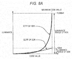
- FIG. 8A is a diagram illustrating an example of an electro-optical transfer function (EOTF) that supports each of HDR and SDR.
- EOTF electro-optical transfer function
- EOTF is commonly called a gamma curve, indicates correspondence between a code value and a luminance value, and converts the code value into the luminance value. That is, EOTF is correspondence information that indicates the correspondence between a plurality of code values and the luminance value.
- FIG. 8B is a diagram illustrating an example of inverse EOTF that supports each of HDR and SDR.
- Inverse EOTF indicates correspondence between the luminance value and the code value, and quantizes and converts the luminance value into the code value, inversely to EOTF. That is, inverse EOTF is correspondence information that indicates the correspondence between the luminance value and the plurality of code values. For example, in a case of representing a luminance value of an HDR-enabled video with a code value of 10-bit gradation, the luminance value in the luminance range of HDR of up to 10,000 nit is quantized and mapped to 1024 integral values from 0 to 1023.
- the luminance value luminance value of the HDR-enabled video
- the luminance range of up to 10,000 nit is converted into the HDR signal of a 10-bit code value by quantization based on inverse EOTF.
- EOTF of HDR HDR-enabled EOTF
- inverse EOTF of HDR HDR-enabled inverse EOTF
- EOTF of SDR SDR-enabled inverse EOTF
- the maximum value of luminance is 10,000 nit. That is, the luminance range of HDR includes the entire luminance range of SDR, and the peak luminance of HDR is larger than the peak luminance of SDR.
- the luminance range of HDR is the luminance range with the maximum value enlarged from 100 nit, which is the maximum value of the luminance range of SDR, to 10,000 nit.
- EOTF of HDR and inverse EOTF of HDR is SMPTE 2084 standardized by the United States Society of Motion Picture and Television Engineers (SMPTE).
- FIG. 9 is an illustrative diagram of a determination method of a code value of the luminance signal to be stored in content, and a process of restoring the luminance value from the code value during playback.
- the luminance signal indicating luminance in this example is an HDR-enabled HDR signal.
- An image after grading is quantized by inverse EOTF of HDR, and the code value corresponding to the luminance value of the image is determined. Processing such as image coding is performed based on this code value, and a video stream is generated. During playback, a decoding result of the stream is converted into a linear signal through inverse quantization based on EOTF of HDR, and the luminance value for each pixel is restored.
- quantization of HDR using inverse EOTF is referred to as "inverse EOTF conversion of HDR”.
- Inverse quantization of HDR using EOTF is referred to as "EOTF conversion of HDR”.
- quantization of SDR using inverse EOTF is referred to as "inverse EOTF conversion of SDR”.
- Inverse quantization of SDR using EOTF is referred to as "EOTF conversion of SDR”.
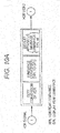
- FIG. 10A is a diagram illustrating an example of display processing for converting an HDR signal and performing HDR display within an HDR TV.
- a maximum value of the luminance range of HDR may not be displayed as it is even if the display apparatus is an HDR TV.
- luminance conversion is performed to adapt a linear signal after inverse quantization using EOTF of HDR to a maximum value of the luminance range of the display apparatus (peak luminance (DPL (Display Peak luminance): example 750 nit)).
- DPL Display Peak luminance
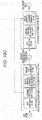
- FIG. 10B is a diagram illustrating an example of display processing for performing HDR display by using an HDR-enabled playback apparatus and SDR TV.
- FIG. 10C is a diagram illustrating an example of display processing for performing HDR display using the HDR-enabled playback apparatus and SDR TV connected to each other via a standard interface.
- FIG. 11 is a block diagram illustrating a configuration of the conversion apparatus and display apparatus according to the exemplary embodiment.
- FIG. 12 is a flowchart illustrating the conversion method and display method to be performed by the conversion apparatus and display apparatus according to the exemplary embodiment.
- conversion apparatus 100 includes HDR EOTF converter 101, luminance converter 102, inverse luminance converter 103, and inverse SDR EOTF converter 104.
- Display apparatus 200 includes display setting unit 201, SDR EOTF converter 202, luminance converter 203, and display unit 204.
- the luminance range of HDR (0 to HPL [nit]) is referred to as “first luminance range”.
- the luminance range of a display (0 to DPL [nit]) is referred to as “second luminance range”.
- the luminance range of SDR (0 to 100 [nit]) is referred to as “third luminance range”.
- the conversion method to be performed by conversion apparatus 100 will be described with reference to FIG. 12 .
- the conversion method includes step S101 to step S104 described below.
- HDR EOTF converter 101 of conversion apparatus 100 acquires the HDR video on which inverse EOTF conversion of HDR is performed.
- HDR EOTF converter 101 of conversion apparatus 100 performs EOTF conversion of HDR on the HDR signal of the acquired HDR video (S101). Accordingly, HDR EOTF converter 101 converts the acquired HDR signal into a linear signal that indicates the luminance value.
- An example of EOTF of HDR is SMPTE 2084.
- luminance converter 102 of conversion apparatus 100 performs first luminance conversion that converts the linear signal converted by HDR EOTF converter 101 by using display characteristic information and content luminance information (S102).
- first luminance conversion the luminance value compatible with the luminance range of HDR (hereinafter referred to as "luminance value of HDR”), which is the first luminance range, is converted into the luminance value compatible with the luminance range of the display (hereinafter referred to as "display luminance value”), which is the second luminance range. Details will be described later.
- HDR EOTF converter 101 functions as an acquisition unit that acquires the HDR signal as a first luminance signal indicating the code value obtained by quantization of the luminance value of a video.
- HDR EOTF converter 101 and luminance converter 102 function as a converter that converts the code value indicated by the HDR signal acquired by the acquisition unit into the display luminance value compatible with the luminance range of the display determined based on the luminance range of the display (display apparatus 200), which is a maximum value (DPL) smaller than a maximum value (HPL) of the luminance range of HDR and larger than 100 nit.
- DPL maximum value
- HPL maximum value
- HDR EOTF converter 101 uses the acquired HDR signal and EOTF of HDR to determine the luminance value of HDR associated with the code value of HDR by EOTF of HDR, the code value of HDR being a first code value indicated by the acquired HDR signal.
- the HDR signal indicates the code value of HDR obtained by quantization of the luminance value of a video (content) by using inverse EOTF of HDR that associates the luminance value in the luminance range of HDR with the plurality of HDR code values.
- step S102 regarding the luminance value of HDR determined in step S101, luminance converter 102 performs the first luminance conversion that determines the display luminance value compatible with the luminance range of the display associated with the luminance value of HDR in advance, and converts the luminance value of HDR compatible with the HDR luminance range into the display luminance value compatible with the luminance range of the display.
- conversion apparatus 100 acquires content luminance information including at least one of a maximum value of luminance (CPL: Content Peak luminance) of a video (content) and an average luminance value (CAL: Content Average luminance) of a video as information regarding the HDR signal.
- CPL first maximum luminance value
- CAL is, for example, an average luminance value which is an average of the luminance values of the plurality of images that constitute the HDR video.
- step S102 conversion apparatus 100 acquires the display characteristic information on display apparatus 200 from display apparatus 200.
- the display characteristic information is information indicating the display characteristic of display apparatus 200, such as a maximum value of luminance that display apparatus 200 can display (DPL), display mode (refer to later description) of display apparatus 200, and input-output characteristic (EOTF supported by the display apparatus).
- conversion apparatus 100 may transmit recommended display setting information (refer to later description, and hereinafter sometimes referred to as "setting information") to display apparatus 200.
- setting information recommended display setting information
- inverse luminance converter 103 of conversion apparatus 100 performs inverse luminance conversion according to the display mode of display apparatus 200. Accordingly, inverse luminance converter 103 performs second luminance conversion that converts the luminance value compatible with the luminance range of the display, which is the second luminance range, into the luminance value compatible with the luminance range of SDR, which is the third luminance range (S103). Details will be described later.
- inverse luminance converter 103 performs the second luminance conversion that determines the luminance value compatible with SDR (hereinafter referred to as "SDR luminance value”) as a third luminance value compatible with the luminance range of SDR with the maximum value of 100 nit associated with the display luminance value in advance, and converts the display luminance value compatible with the luminance range of the display into the SDR luminance value compatible with the luminance range of SDR.
- SDR luminance value the luminance value compatible with SDR
- inverse SDR EOTF converter 104 of conversion apparatus 100 performs inverse SDR EOTF conversion to generate the pseudo HDR video (S104). That is, inverse SDR EOTF converter 104 uses inverse EOTF (Electro-Optical Transfer Function) of SDR (Standard Dynamic Range), which is third correspondence information that associates the luminance value in the luminance range of HDR with a plurality of third code values, to quantize the determined luminance value of SDR, determines the third code value obtained by quantization, and converts the luminance value of SDR compatible with the luminance range of SDR into the SDR signal as a third luminance signal indicating the third code value, thereby generating the pseudo HDR signal.
- SDR Standard Dynamic Range
- each of the third code values is a code value compatible with SDR, and hereinafter referred to as "code value of SDR". That is, the SDR signal is expressed by the code value of SDR obtained by quantization of the luminance value of a video by using inverse EOTF of SDR that associates the luminance value in the luminance range of SDR with the plurality of code values of SDR. Then, conversion apparatus 100 outputs the pseudo HDR signal (SDR signal) generated in step S104 to display apparatus 200.
- Conversion apparatus 100 performs the first luminance conversion and the second luminance conversion on the luminance value of HDR obtained by performing inverse quantization on the HDR signal to generate the luminance value of SDR compatible with pseudo HDR. Conversion apparatus 100 quantizes the luminance value of SDR by using EOTF of SDR to generate the SDR signal compatible with pseudo HDR.
- the luminance value of SDR is a numerical value within the luminance range of 0 to 100 nit compatible with SDR
- the luminance value of SDR is a numerical value different from the luminance value within the luminance range of 0 to 100 nit compatible with SDR obtained by performing the luminance conversion using EOTF of HDR and EOTF of SDR on the luminance value of HDR.
- display setting unit 201 of display apparatus 200 uses the setting information acquired from conversion apparatus 100 to set display settings of display apparatus 200 (S105).
- display apparatus 200 is the SDR TV.
- the setting information is information indicating display settings recommended to the display apparatus, and is information indicating how to perform EOTF on the pseudo HDR video and which display settings to use for displaying a beautiful video (that is, information for switching the display settings of display apparatus 200 to optimal display settings).
- the setting information includes, for example, a gamma curve characteristic of output in the display apparatus, display modes such as a living mode (normal mode) and dynamic mode, and a numerical value of a back light (brightness).
- a message may be displayed on display apparatus 200 for prompting the user to change the display settings of display apparatus 200 (hereinafter sometimes referred to as "SDR display”) by manual operation. Details will be described later.
- step S105 display apparatus 200 acquires the SDR signal (pseudo HDR signal) and the setting information indicating the display settings recommended to display apparatus 200 in displaying a video.
- Display apparatus 200 only needs to acquire the SDR signal (pseudo HDR signal) before step S106, and may acquire the SDR signal after step S105.
- SDR EOTF converter 202 of display apparatus 200 performs EOTF conversion of SDR on the acquired pseudo HDR signal (S106). That is, SDR EOTF converter 202 performs inverse quantization on the SDR signal (pseudo HDR signal) by using EOTF of SDR. Accordingly, SDR EOTF converter 202 converts the code value of SDR indicated by the SDR signal into the luminance value of SDR.
- luminance converter 203 of display apparatus 200 performs the luminance conversion according to the display mode that is set for display apparatus 200. Accordingly, luminance converter 203 performs third luminance conversion that converts the luminance value of SDR compatible with the luminance range of SDR (0 to 100 [nit]) into the display luminance value compatible with the luminance range of the display (0 to DPL [nit]) (S107). Details will be described later.
- step S106 and step S107 display apparatus 200 converts the third code value indicated by the acquired SDR signal (pseudo HDR signal) into the display luminance value compatible with the luminance range of the display (0 to DPL [nit]) by using the setting information acquired in step S105.
- step S106 in the conversion from the SDR signal (pseudo HDR signal) into the display luminance value, in step S106, by using EOTF that associates the luminance value in the luminance range of SDR with the plurality of third code values, display apparatus 200 determines the luminance value of SDR associated with the code value of SDR indicated by the acquired SDR signal by EOTF of SDR.
- step S107 display apparatus 200 performs the third luminance conversion that determines the display luminance value compatible with the luminance range of the display associated in advance with the determined luminance value of SDR, and converts the luminance value of SDR compatible with the luminance range of SDR into the display luminance value compatible with the luminance range of the display.
- display unit 204 of display apparatus 200 displays the pseudo HDR video on display apparatus 200 based on the converted display luminance value (S108).
- FIG. 13A is a diagram illustrating an example of the first luminance conversion.
- Luminance converter 102 of conversion apparatus 100 performs the first luminance conversion of converting the linear signal (luminance value of HDR) obtained in step S101 by using the display characteristic information and the content luminance information on the HDR video.
- the first luminance conversion converts the luminance value of HDR (input luminance value) into the display luminance value (output luminance value) that does not exceed the display peak luminance (DPL).
- DPL is determined using the maximum luminance of the SDR display and the display mode which are the display characteristic information.
- the display mode is, for example, mode information including a theater mode of relatively dark display on the SDR display and a dynamic mode of relatively bright display.
- DPL (second maximum luminance value) is a maximum value of luminance the SDR display can display in the display mode of current setting. That is, in the first luminance conversion, DPL as the second maximum luminance value is determined by using the display characteristic information which is information indicating the display characteristic of the SDR display.
- CAL and CPL out of the content luminance information are used.
- the luminance value equal to or less than vicinity of CAL is identical between before and after the conversion, and only the luminance value equal to or greater than vicinity of CPL is changed. That is, as illustrated in FIG. 13A , in the first luminance conversion, when the luminance value of HDR is equal to or less than CAL, the luminance value of HDR is not converted, and the luminance value of HDR is determined as the display luminance value.
- DPL as the second maximum luminance value is determined as the display luminance value.
- the peak luminance of the HDR video (CPL) is used.
- DPL is determined as the display luminance value.
- step S101 may be clipped to a value that does not exceed DPL.
- luminance conversion can simplify processing performed by conversion apparatus 100, and can achieve size reduction, low power consumption, and high-speed processing of the apparatus.
- FIG. 13B is a diagram illustrating another example of the first luminance conversion.
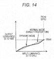
- FIG. 14 is a diagram illustrating the second luminance conversion.
- Inverse luminance converter 103 of conversion apparatus 100 applies inverse luminance conversion according to the display mode to the display luminance value in the luminance range of the display converted in the first luminance conversion of step S102 (0 to DPL [nit]).
- the inverse luminance conversion is processing for acquiring the display luminance value in the luminance range of the display after processing of step S102 (0 to DPL [nit]) when the luminance conversion processing (step S107) according to the display mode is performed by the SDR display. That is, the second luminance conversion is the inverse luminance conversion of the third luminance conversion.
- the second luminance conversion converts the display luminance value in the luminance range of the display (input luminance value), which is the second luminance range, into the luminance value of SDR in the luminance range of SDR (output luminance value), which is the third luminance range.
- a conversion equation is switched according to the display mode of the SDR display. For example, when the display mode of the SDR display is the normal mode, the luminance conversion is performed to a direct proportion value in direct proportion to the display luminance value.
- the luminance conversion when the display mode of the SDR display is the dynamic mode in which a high-luminance pixel becomes brighter and a low-luminance pixel becomes darker than pixels in the normal mode, the luminance conversion is performed by using an inverse function thereof so that the luminance value of SDR of the low-luminance pixel is converted into a value higher than the direct proportion value in direct proportion to the display luminance value, and that the luminance value of SDR of the high-luminance pixel is converted into a value lower than the direct proportion value in direct proportion to the display luminance value.
- the luminance-related information according to the display characteristic information refers, for example as illustrated in FIG. 14 , to information that associates the display luminance value (input luminance value) with the luminance value of SDR (output luminance value) defined for each display parameter of the SDR display (display mode).
- FIG. 15 is a flowchart illustrating detailed processing of the display settings.
- step S105 display setting unit 201 of the SDR display performs step S201 to step S208 described below.
- display setting unit 201 uses the setting information to determine whether EOTF that is set for the SDR display (EOTF for SDR display) is consistent with EOTF assumed at a time of generation of the pseudo HDR video (SDR signal) (S201).
- display setting unit 201 determines that EOTF that is set for the SDR display differs from EOTF indicated by the setting information (EOTF consistent with the pseudo HDR video) (Yes in S201), display setting unit 201 determines whether EOTF for the SDR display is switchable on a system side (S202).
- display setting unit 201 determines that EOTF for the SDR display is switchable, display setting unit 201 uses the setting information to switch EOTF for the SDR display to appropriate EOTF (S203).
- step S201 in setting of the display settings (S105), display setting unit 201 sets EOTF that is set for the SDR display as recommended EOTF according to the acquired setting information. This allows determination of the luminance value of SDR by using the recommended EOTF in step S106 to be performed after step S105.
- display setting unit 201 determines that EOTF for the SDR display is not switchable on the system side (No in S202), display setting unit 201 displays a message on a screen prompting the user to change EOTF by manual operation (S204). For example, display setting unit 201 displays a message on the screen saying "Set display gamma to 2.4". That is, when display setting unit 201 cannot switch EOTF that is set for the SDR display in setting of the display settings (S105), display setting unit 201 displays the message on the SDR display for prompting the user to switch EOTF that is set for the SDR display (EOTF for the SDR display) to the recommended EOTF.
- SDR display displays the pseudo HDR video (SDR signal)
- display setting unit 201 uses the setting information to determine whether the display parameter of the SDR display matches the setting information (S205).
- display setting unit 201 determines that the display parameter that is set for the SDR display differs from the setting information (Yes in S205), display setting unit 201 determines whether the display parameter of the SDR display is switchable (S206).
- display setting unit 201 determines that the display parameter of the SDR display is switchable (Yes in S206)
- display setting unit 201 switches the display parameter of the SDR display in accordance with the setting information (S207).
- step S105 in setting of the display settings (S105), display setting unit 201 sets the display parameter that is set for the SDR display as a recommended display parameter according to the acquired setting information.
- display setting unit 201 determines that the display parameter of the SDR display is not switchable on the system side (No in S206), display setting unit 201 displays a message on the screen prompting the user to change the display parameter that is set for the SDR display by manual operation (S208). For example, display setting unit 201 displays a message on the screen saying "Set display mode to dynamic mode, and increase back light to maximum level". That is, in setting (S105), when the display parameter that is set for the SDR display cannot be switched, display setting unit 201 displays the message on the SDR display for prompting the user to switch the display parameter that is set for the SDR display to the recommended display parameter.
- FIG. 16 is a diagram illustrating the third luminance conversion.
- Luminance converter 203 of display apparatus 200 converts the luminance value of SDR in the luminance range of SDR (0 to 100 [nit]) into (0 to DPL [nit]) according to the display mode that is set in step S105. This processing is performed so as to become an inverse function of the inverse luminance conversion for each mode of S103.
- the conversion equation is switched according to the display mode of the SDR display.
- the display mode of the SDR display is the normal mode (that is, when the set display parameter is a parameter compatible with the normal mode)
- the luminance conversion of the display luminance value is performed to the direct proportion value in direct proportion to the luminance value of SDR.
- the luminance conversion when the display mode of the SDR display is the dynamic mode in which a high-luminance pixel becomes brighter and a low-luminance pixel becomes darker than pixels in the normal mode, the luminance conversion is performed so that the display luminance value of the low-luminance pixel is converted into a value lower than the direct proportion value in direct proportion to the luminance value of SDR, and that the display luminance value of the high-luminance pixel is converted into a value higher than the direct proportion value in direct proportion to the luminance value of SDR.
- the luminance-related information according to the display parameter refers, for example as illustrated in FIG. 16 , to information that associates the luminance value of SDR (input luminance value) with the display luminance value (output luminance value) defined for each display parameter of the SDR display (display mode).
- a normal SDR TV whose input signal is 100 nit, has capability of visual representation of 200 nit or more adapted to viewing environments (dark room: cinema mode, bright room: dynamic mode, etc.). However, since a luminance upper limit of the input signal to the SDR TV is determined as 100 nit, the capability cannot be used directly.
- HDR to pseudo HDR conversion processing is performed so that gradation of the luminance range exceeding 100 nit be maintained to some extent, instead of conversion of the HDR video into the SDR video of 100 nit or less. Therefore, the HDR video may be displayed on the SDR TV as a pseudo HDR video close to the original HDR video.
- the Blu-ray device When this "HDR to pseudo HDR conversion processing" technique is applied to Blu-ray with an HDR disc storing only the HDR signal and the SDR TV connected to the Blu-ray device as illustrated in FIG. 17 , the Blu-ray device performs the "HDR to pseudo HDR conversion processing", converts the HDR signal into the pseudo HDR signal, and sends the pseudo HDR signal to the SDR TV. This allows the SDR TV to display a video with a pseudo HDR effect by converting the received pseudo HDR signal into a luminance value. Thus, even where there is no HDR-enabled TV, when the HDR-enabled BD and HDR-enabled Blu-ray device are prepared, even the SDR TV can display the pseudo HDR video with higher display quality than that of the SDR video.
- the HDR-enabled TV is required for watching the HDR video
- the pseudo HDR video that provides feeling of an HDR-like effect can be watched on the existing SDR TV. Accordingly, wide use of HDR-enabled Blu-ray is expected.
- the HDR signal sent by broadcast, package media such as Blu-ray, and Internet delivery such as OTT is converted into the pseudo HDR signal by performing the HDR-pseudo HDR conversion processing. This allows the HDR signal to be displayed on the existing SDR TV as the pseudo HDR video.
- the exemplary embodiment has been described by way of example of the technique to be disclosed in this application.
- the technique in the present disclosure is not limited to this example, and is also applicable to the exemplary embodiment to which change, replacement, addition, omission, etc. are made as appropriate. It is also possible to make a new exemplary embodiment by combining components described in the aforementioned exemplary embodiment.
- the HDR video is, for example, a video within a Blu-ray disc, DVD, video delivery site on the Internet, broadcast, and HDD.
- Conversion apparatus 100 may exist within a disc player, disc recorder, set-top box, TV, personal computer, and smart phone. Conversion apparatus 100 may exist within a server apparatus on the Internet.
- Display apparatus 200 is, for example, a TV, personal computer, and smart phone.
- the display characteristic information to be acquired by conversion apparatus 100 may be acquired from display apparatus 200 through an HDMI cable or LAN cable by using HDMI or other communication protocols.
- As the display characteristic information to be acquired by conversion apparatus 100 display characteristic information included in model information on display apparatus 200, etc. may be acquired via the Internet.
- the user may perform manual operation to set the display characteristic information in conversion apparatus 100.
- Acquisition of the display characteristic information by conversion apparatus 100 may be performed immediately before pseudo HDR video generation (steps S101 to S104), and may be performed with timing of initial setting of a device or display connection. For example, acquisition of the display characteristic information may be performed immediately before conversion into the display luminance value, and may be performed with timing with which conversion apparatus 100 is connected to display apparatus 200 with an HDMI cable for the first time.
- One set of information items including CPL and CAL of the HDR video may exist per one piece of content, and may exist for each scene. That is, in the conversion method may be acquired luminance information (CPL, CAL) compatible with each of a plurality of scenes in a video, the luminance information including, for each of the scenes, at least one of a first maximum luminance value which is a maximum value out of the luminance values of a plurality of images that constitute the scene, and an average luminance value which is an average of the luminance values of the plurality of images that constitute the scene.
- the display luminance value may be determined in accordance with luminance information corresponding to each of the plurality of scenes.
- CPL and CAL may be provided in a medium (such as a Blu-ray disc and DVD) identical to a medium of the HDR video, and may be acquired from a place different from the HDR video, such as conversion apparatus 100 acquires CPL and CAL from the Internet. That is, the luminance information including at least one of CPL and CAL may be acquired as metadata information on the video, and may be acquired via a network.
- a medium such as a Blu-ray disc and DVD
- conversion apparatus 100 acquires CPL and CAL from the Internet. That is, the luminance information including at least one of CPL and CAL may be acquired as metadata information on the video, and may be acquired via a network.
- CPL In the first luminance conversion of conversion apparatus 100 (HPL to DPL), CPL, CAL, and the display peak luminance (DPL) may not be used, and fixed values may be used.
- the fixed values may be changeable from outside.
- CPL, CAL, and DPL may be switched among several types, for example, DPL may be only three types including, 200 nit, 400 nit, and 800 nit, and a value closest to the display characteristic information may be used.
- EOTF of HDR may not be SMPTE 2084, and EOTF of HDR of another type may be used.
- the maximum luminance of the HDR video (HPL) may not be 10,000 nit, and may be, for example, 4,000 nit or 1,000 nit.
- a bit width of the code value may be, for example, 16, 14, 12, 10, or 8 bits.
- inverse EOTF conversion of SDR is determined from the display characteristic information
- a fixed (changeable from outside) conversion function may be used.
- Inverse EOTF conversion of SDR may use, for example, a function prescribed by Rec. ITU-R BT.1886.
- Types of inverse EOTF conversion of SDR may be limited to several types, and a type closest to an input-output characteristic of display apparatus 200 may be selected and used.
- a fixed mode may be used as the display mode, and the display mode may not be included in the display characteristic information.
- Conversion apparatus 100 may not transmit the setting information, display apparatus 200 may use fixed display settings, and may not change the display settings. In this case, display setting unit 201 is unnecessary.
- the setting information may be flag information indicating whether a video is the pseudo HDR video, and for example, when a video is the pseudo HDR video, settings may be changed to brightest display. That is, in setting of the display settings (S105), when the acquired setting information indicates a signal indicating the pseudo HDR video that is converted using DPL, brightness settings of display apparatus 200 may be switched to settings of brightest display.
- the first luminance conversion (HPL to DPL) of conversion apparatus 100 is performed by the next formula, for example.
- V ⁇ L a * ln L + b M for 0 ⁇ L ⁇ S 1 for S 1 ⁇ L ⁇ S 2 for S 2 ⁇ L
- L denotes a luminance value normalized to 0 to 1
- S1, S2, a, b, and M are values to be set based on CAL, CPL, and DPL.
- V is a converted luminance value normalized to 0 to 1.
- CAL is 300 nit
- CPL is 2,000 nit
- DPL is 750 nit
- conversion is not performed until CAL + 50 nit
- conversion is performed for 350 nit or more
- respective values are as follows, for example.
- the display luminance value corresponding to the luminance value of HDR is determined using a natural logarithm.
- the conversion equation may be changed according to content, and it is possible to perform conversion so that gradation of HDR may be maintained as much as possible. It is also possible to inhibit an adverse effect such as too dark and too bright. Specifically, by mapping the content peak luminance of the HDR video on the display peak luminance, gradation is maintained as much as possible. In addition, overall brightness is kept from changing by not changing a pixel value equal to or less than vicinity of the average luminance.
- the conversion equation may be changed in accordance with display environments of the SDR display.
- a video with feeling of HDR may be displayed with gradation and brightness similar to gradation and brightness of an original HDR video.
- the HDR video is displayed with little reduction in gradation of the HDR video until brightness that is displayable by the SDR display. For non-displayable brightness levels, the luminance value is decreased to a displayable brightness level.
- a video signal and a graphics signal are multiplexed as independent data.
- each signal is decoded individually, and decoding results are composited and displayed. Specifically, a plane of subtitles or menus is superimposed on a plane of the video.
- the graphics signal of subtitles or menus may be SDR.
- the following two kinds of conversion (a) and (b) are possible.
- peak luminance of the graphics is 100 nit both in scheme (a) and scheme (b), for example, if DPL is high luminance as high as 1000 nit, luminance of the graphics which remains 100 nit may lead to reduction in the luminance of the graphics of the video after HPL to DPL conversion. In particular, a bad influence is assumed such as dark subtitles superimposed on the video. Accordingly, the luminance of the graphics may also be converted according to a value of DPL. For example, a rule of proportion of the luminance of subtitles to the DPL value may be determined in advance, and the luminance of subtitles may be converted based on a setting value. Graphics other than subtitles, such as menus, can be processed similarly.
- FIG. 18 is a diagram illustrating the multiplex data to be stored in the dual disc.
- the HDR signal and the SDR signal are stored as multiplex streams different from each other.
- data of a plurality of media such as video, audio, subtitles, and graphics
- M2TS MPEG-2TS-based multiplexing scheme
- These multiplex streams are referenced from metadata for playback control, such as a play list.
- a player selects the multiplex stream to be played, or data of individual language stored in the multiplex stream by analyzing the metadata.
- This example indicates a case where the play list for HDR and the play list for SDR are stored individually, and where each play list references the HDR signal or the SDR signal. Identification information or the like indicating that both the HDR signal and the SDR signal are stored may be indicated separately.
- the data volume of video can be reduced by using a video coding scheme with a high compression ratio.
- a video coding scheme with a high compression ratio.
- changing MPEG-4 AVC used in conventional Blu-ray into High Efficiency Video Coding (HEVC) is expected to provide improvement in the compression ratio by a factor of 1.6 to 2.
- Only a combination that fits into capacity of an optical disc may be allowed to be stored in a dual disc, such as storing a combination of two 2K streams or a combination of a 4K stream and a 2K stream, including a combination of a 2K HDR stream and a 2K SDR stream, and a combination of a 4K SDR stream and a 2K HDR stream, by prohibiting storage of two 4K streams.
- FIG. 19 is a flowchart illustrating a playback operation of the dual disc.
- the playback apparatus determines whether an optical disc to be played is a dual disc (S301). When it is determined that the optical disc to be played is a dual disc (Yes in S301), the playback apparatus determines whether an output destination TV is an HDR TV or SDR TV (S302). When it is determined that the TV is an HDR TV (Yes in S302), the processing advances to step S303. When it is determined that the TV is an SDR TV (No in S302), the processing advances to step S304. In step S303, the playback apparatus acquires a video signal of HDR from the multiplex stream including the HDR signal within the dual disc, and decodes and outputs the video signal to the HDR TV.
- step S304 the playback apparatus acquires a video signal of SDR from the multiplex stream including the SDR signal within the dual disc, and decodes and outputs the video signal to the SDR TV.
- the playback apparatus determines whether playback is possible by a predetermined method, and decides a playback method based on a result of the determination (S305).
- HDR to pseudo HDR conversion processing is implemented that allows conversion of the HDR video into a pseudo HDR video similar to an original HDR and display on the SDR TV, by converting the HDR video while maintaining gradation of a region exceeding 100 nit to some extent, instead of conversion of the HDR video into the SDR video of 100 nit or less.
- the conversion method of the "HDR to pseudo HDR conversion processing" may be switched in accordance with the display characteristic of the SDR TV (maximum luminance, input-output characteristic, and display mode).
- Conceivable acquisition methods of display characteristic information include (1) automatic acquisition through HDMI or a network, (2) generation by causing the user to input information such as a manufacturer name and model number, and (3) acquisition from a cloud, etc. using the information such as the manufacturer name and the model number.
- Conceivable acquisition timing of the display characteristic information by conversion apparatus 100 includes (1) acquisition immediately before pseudo HDR conversion, and (2) when connected to display apparatus 200 (such as the SDR TV) for the first time (when the connection is established).
- the conversion method may be switched in accordance with luminance information on the HDR video (CAL, CPL).
- Examples of the conceivable acquisition method of the luminance information on the HDR video by conversion apparatus 100 include (1) acquisition as metadata information appended to the HDR video, (2) acquisition by causing the user to input title information on content, and (3) acquisition from a cloud, etc. using input information that is input by the user.
- Details of the conversion method include (1) conversion so that the luminance would not exceed DPL, (2) conversion so that CPL would become DPL, (3) not changing the luminance equal to or less than CAL and vicinity thereof, (4) conversion using a natural logarithm, and (5) clip processing at DPL.
- this conversion method may include transmitting display settings such as a display mode and display parameter of the SDR TV to display apparatus 200 for switching. For example, a message prompting the user to make display settings may be displayed on a screen.
- each component may be made of dedicated hardware, or may be implemented through execution of a software program suitable for each component.
- Each component may be implemented by a program execution unit, such as a CPU or a processor, reading and executing the software program recorded in a recording medium such as a hard disk or a semiconductor memory.
- the present disclosure is not limited to this exemplary embodiment.
- the present disclosure is useful as a conversion method, conversion apparatus, and the like that can appropriately convert luminance in the first luminance range into luminance in the second luminance range with reduced luminance range.
Landscapes
- Engineering & Computer Science (AREA)
- Multimedia (AREA)
- Signal Processing (AREA)
- Theoretical Computer Science (AREA)
- Physics & Mathematics (AREA)
- General Physics & Mathematics (AREA)
- Computer Hardware Design (AREA)
- Databases & Information Systems (AREA)
- Human Computer Interaction (AREA)
- General Engineering & Computer Science (AREA)
- Controls And Circuits For Display Device (AREA)
- Two-Way Televisions, Distribution Of Moving Picture Or The Like (AREA)
- Picture Signal Circuits (AREA)
- Transforming Electric Information Into Light Information (AREA)
- Television Signal Processing For Recording (AREA)
Applications Claiming Priority (3)
| Application Number | Priority Date | Filing Date | Title |
|---|---|---|---|
| US201462010096P | 2014-06-10 | 2014-06-10 | |
| JP2015089834 | 2015-04-24 | ||
| PCT/JP2015/002612 WO2015190045A1 (ja) | 2014-06-10 | 2015-05-25 | 変換方法および変換装置 |
Publications (3)
| Publication Number | Publication Date |
|---|---|
| EP3157243A1 true EP3157243A1 (de) | 2017-04-19 |
| EP3157243A4 EP3157243A4 (de) | 2017-06-28 |
| EP3157243B1 EP3157243B1 (de) | 2024-07-03 |
Family
ID=54833163
Family Applications (1)
| Application Number | Title | Priority Date | Filing Date |
|---|---|---|---|
| EP15807114.2A Active EP3157243B1 (de) | 2014-06-10 | 2015-05-25 | Umwandlungsverfahren und umwandlungsvorrichtung |
Country Status (6)
| Country | Link |
|---|---|
| US (11) | US10291881B2 (de) |
| EP (1) | EP3157243B1 (de) |
| JP (6) | JP5914902B1 (de) |
| CN (5) | CN106105177B (de) |
| MX (1) | MX363812B (de) |
| WO (1) | WO2015190045A1 (de) |
Cited By (1)
| Publication number | Priority date | Publication date | Assignee | Title |
|---|---|---|---|---|
| EP3734954A4 (de) * | 2017-12-27 | 2021-01-27 | Panasonic Intellectual Property Management Co., Ltd. | Anzeigevorrichtung und anzeigeverfahren |
Families Citing this family (32)
| Publication number | Priority date | Publication date | Assignee | Title |
|---|---|---|---|---|
| MX357792B (es) * | 2014-06-10 | 2018-07-25 | Panasonic Ip Man Co Ltd | Sistema de visualizacion, metodo de visualizacion y aparato de visualizacion. |
| CN106105177B (zh) | 2014-06-10 | 2019-09-27 | 松下知识产权经营株式会社 | 变换方法及变换装置 |
| JP2017120330A (ja) * | 2015-12-28 | 2017-07-06 | 日本放送協会 | 輝度調整装置および輝度調整プログラム |
| JP6451669B2 (ja) | 2016-03-04 | 2019-01-16 | ソニー株式会社 | 評価装置、評価方法およびカメラシステム |
| JP6757157B2 (ja) * | 2016-03-29 | 2020-09-16 | キヤノン株式会社 | 投影装置およびその制御方法 |
| JP6700908B2 (ja) * | 2016-03-30 | 2020-05-27 | キヤノン株式会社 | 表示装置及び表示方法 |
| JP2017198733A (ja) * | 2016-04-25 | 2017-11-02 | キヤノン株式会社 | 投射型表示装置および投射型表示システム |
| US20170353704A1 (en) * | 2016-06-01 | 2017-12-07 | Apple Inc. | Environment-Aware Supervised HDR Tone Mapping |
| WO2018003643A1 (ja) | 2016-07-01 | 2018-01-04 | シャープ株式会社 | 映像表示装置、テレビジョン受像機、送信装置、制御プログラム及び記録媒体 |
| JP6739257B2 (ja) * | 2016-07-06 | 2020-08-12 | キヤノン株式会社 | 画像処理装置とその制御方法及びプログラム |
| JP2018013696A (ja) * | 2016-07-22 | 2018-01-25 | キヤノン株式会社 | 画像処理装置および表示装置 |
| EP3511928B1 (de) * | 2016-09-09 | 2022-01-12 | Panasonic Intellectual Property Management Co., Ltd. | Anzeigevorrichtung und signalverarbeitungsverfahren |
| WO2018062022A1 (ja) * | 2016-09-28 | 2018-04-05 | パナソニックIpマネジメント株式会社 | 調整装置、調整方法およびプログラム |
| JP6872693B2 (ja) * | 2016-09-28 | 2021-05-19 | パナソニックIpマネジメント株式会社 | 調整装置、調整方法およびプログラム |
| JP2018117281A (ja) * | 2017-01-19 | 2018-07-26 | 日本放送協会 | 文字スーパー合成装置及びそのプログラム |
| KR102308192B1 (ko) * | 2017-03-09 | 2021-10-05 | 삼성전자주식회사 | 디스플레이 장치 및 그 제어 방법 |
| CN106911903A (zh) * | 2017-03-15 | 2017-06-30 | 四川长虹电器股份有限公司 | 一种sdr信号转hdr信号效果的画质数据处理方法 |
| JP2018180266A (ja) * | 2017-04-13 | 2018-11-15 | キヤノン株式会社 | 表示装置およびその制御方法 |
| CN107277399B (zh) | 2017-06-09 | 2020-10-20 | 深圳Tcl新技术有限公司 | 电视终端及hdr图像转为sdr的方法和计算机可读存储介质 |
| JP6948173B2 (ja) * | 2017-06-28 | 2021-10-13 | キヤノン株式会社 | 画像処理装置及び方法、撮像装置、及び、撮像システム |
| CN107545871B (zh) * | 2017-09-30 | 2020-03-24 | 青岛海信电器股份有限公司 | 图像亮度处理方法及装置 |
| US10600163B2 (en) | 2017-11-22 | 2020-03-24 | Interdigital Vc Holdings, Inc. | Method and device for reconstructing a display adapted HDR image |
| WO2019245876A1 (en) * | 2018-06-18 | 2019-12-26 | Dolby Laboratories Licensing Corporation | Image capture methods and systems |
| US11354789B2 (en) * | 2018-09-03 | 2022-06-07 | Canon Kabushiki Kaisha | Image processing apparatus and control method thereof |
| JP7418690B2 (ja) * | 2019-10-25 | 2024-01-22 | 株式会社Jvcケンウッド | 表示制御装置、表示システム、表示制御方法及びプログラム |
| CN113554973B (zh) | 2020-04-08 | 2022-11-22 | 华为技术有限公司 | 一种显示亮度调整方法及相关装置 |
| CN111669532B (zh) * | 2020-06-02 | 2021-08-10 | 国家广播电视总局广播电视科学研究院 | 一种高动态范围视频端到端实现方法 |
| US11412174B2 (en) * | 2020-09-22 | 2022-08-09 | Microsoft Technology Licensing, Llc | Efficient electro-optical transfer function (EOTF) curve for standard dynamic range (SDR) content |
| JP2022144005A (ja) * | 2021-03-18 | 2022-10-03 | キヤノン株式会社 | 画像処理装置、表示装置、画像処理方法、及び、プログラム |
| CN115797152A (zh) * | 2021-09-10 | 2023-03-14 | 北京字跳网络技术有限公司 | 一种颜色映射色卡生成方法及装置 |
| CN115797237A (zh) * | 2021-09-10 | 2023-03-14 | 北京字跳网络技术有限公司 | 一种图像处理方法及装置 |
| CN115797155A (zh) * | 2021-09-10 | 2023-03-14 | 北京字跳网络技术有限公司 | 一种图像处理方法及装置 |
Family Cites Families (77)
| Publication number | Priority date | Publication date | Assignee | Title |
|---|---|---|---|---|
| US5068718A (en) * | 1988-11-04 | 1991-11-26 | Fuji Photo Film Co., Ltd. | Image quality correcting system for use with an imaging apparatus |
| KR100371428B1 (ko) * | 1995-03-28 | 2003-04-08 | 마츠시타 덴끼 산교 가부시키가이샤 | 화상기록장치및화상재생장치 |
| JPH0946584A (ja) * | 1995-07-31 | 1997-02-14 | Sony Corp | 撮像装置 |
| JP2000338922A (ja) * | 1999-03-25 | 2000-12-08 | Victor Co Of Japan Ltd | 映像処理装置 |
| EP1353314A1 (de) * | 2002-04-11 | 2003-10-15 | Deutsche Thomson-Brandt Gmbh | Verfahren und Vorrichtung zur Verbesserung der Grauwertauflösung einer Bildanzeigevorrichtung |
| US7483083B2 (en) * | 2003-04-16 | 2009-01-27 | Intervideo, Inc. | Movie enhancement |
| JP4271978B2 (ja) * | 2003-04-18 | 2009-06-03 | 株式会社日立製作所 | 映像表示装置 |
| JP4401884B2 (ja) * | 2004-07-16 | 2010-01-20 | キヤノン株式会社 | 映像信号処理装置及び方法 |
| US7433514B2 (en) * | 2005-07-13 | 2008-10-07 | Canon Kabushiki Kaisha | Tone mapping of high dynamic range images |
| JP2007082181A (ja) * | 2005-08-16 | 2007-03-29 | Konica Minolta Holdings Inc | 撮像装置及び画像処理方法 |
| US7932914B1 (en) * | 2005-10-20 | 2011-04-26 | Nvidia Corporation | Storing high dynamic range data in a low dynamic range format |
| JP2007121953A (ja) * | 2005-10-31 | 2007-05-17 | Nanao Corp | 表示方法及び表示装置 |
| CN1984303A (zh) * | 2005-12-15 | 2007-06-20 | 杨建兴 | 视频信号转换器 |
| JP4720537B2 (ja) | 2006-02-27 | 2011-07-13 | コニカミノルタホールディングス株式会社 | 撮像装置 |
| US7843493B2 (en) | 2006-01-31 | 2010-11-30 | Konica Minolta Holdings, Inc. | Image sensing apparatus and image processing method |
| US8014445B2 (en) * | 2006-02-24 | 2011-09-06 | Sharp Laboratories Of America, Inc. | Methods and systems for high dynamic range video coding |
| WO2007143340A2 (en) * | 2006-06-02 | 2007-12-13 | Clairvoyante, Inc | High dynamic contrast display system having multiple segmented backlight |
| JP2008016940A (ja) * | 2006-07-03 | 2008-01-24 | Seiko Instruments Inc | コントラスト自動調整方法 |
| KR101244679B1 (ko) * | 2006-07-27 | 2013-03-18 | 삼성전자주식회사 | 밝기에 따른 동적 이득 조절 방법 및 장치 |
| JP5145017B2 (ja) | 2006-12-05 | 2013-02-13 | 日本放送協会 | 画像信号処理装置 |
| JP5211732B2 (ja) * | 2008-02-14 | 2013-06-12 | ソニー株式会社 | 点灯期間設定方法、表示パネルの駆動方法、点灯条件設定装置、半導体デバイス、表示パネル及び電子機器 |
| JP2009253834A (ja) * | 2008-04-09 | 2009-10-29 | Olympus Corp | 画像信号処理装置、撮像システム、画像信号処理プログラム、画像信号処理方法 |
| JP2010002876A (ja) * | 2008-05-19 | 2010-01-07 | Sony Ericsson Mobilecommunications Japan Inc | 表示装置、表示制御方法および表示制御プログラム |
| JP5275122B2 (ja) * | 2008-05-30 | 2013-08-28 | パナソニック株式会社 | ダイナミックレンジ圧縮装置、ダイナミックレンジ圧縮方法、プログラム、集積回路および撮像装置 |
| US8165393B2 (en) * | 2008-06-05 | 2012-04-24 | Microsoft Corp. | High dynamic range texture compression |
| JP2009038818A (ja) * | 2008-09-22 | 2009-02-19 | Fujifilm Corp | 画像処理方法及びデジタルカメラ |
| US8184112B2 (en) * | 2008-09-24 | 2012-05-22 | Global Oled Technology Llc | Increasing dynamic range of display output |
| US8339475B2 (en) * | 2008-12-19 | 2012-12-25 | Qualcomm Incorporated | High dynamic range image combining |
| WO2010077325A2 (en) * | 2008-12-29 | 2010-07-08 | Thomson Licensing | Method and apparatus for adaptive quantization of subband/wavelet coefficients |
| JP2010166139A (ja) * | 2009-01-13 | 2010-07-29 | Pioneer Electronic Corp | 映像信号処理方法 |
| JP5249077B2 (ja) * | 2009-02-17 | 2013-07-31 | キヤノン株式会社 | 撮像装置及び画像処理方法 |
| CN102349290B (zh) * | 2009-03-10 | 2014-12-17 | 杜比实验室特许公司 | 扩展动态范围和扩展维数图像信号转换 |
| WO2010105036A1 (en) * | 2009-03-13 | 2010-09-16 | Dolby Laboratories Licensing Corporation | Layered compression of high dynamic range, visual dynamic range, and wide color gamut video |
| CN101547362B (zh) * | 2009-05-06 | 2010-11-24 | 天津大学 | 宽色域数字电视信号的兼容传输方法 |
| CN102422322B (zh) * | 2009-05-11 | 2015-01-21 | 杜比实验室特许公司 | 用于在目标环境下在装置处再现来自源环境的图像的色貌的方法和设备 |
| JP4668342B2 (ja) * | 2009-08-31 | 2011-04-13 | シャープ株式会社 | 液晶表示装置 |
| JPWO2011040021A1 (ja) * | 2009-09-29 | 2013-02-21 | パナソニック株式会社 | 表示装置および表示方法 |
| WO2011042229A1 (en) * | 2009-10-08 | 2011-04-14 | International Business Machines Corporation | Method and system for transforming a digital image from a low dynamic range (ldr) image to a high dynamic range (hdr) image |
| KR101648762B1 (ko) * | 2009-11-03 | 2016-08-18 | 한양대학교 산학협력단 | 입력 영상의 동적 범위를 변환하는 방법 및 장치 |
| JP5383454B2 (ja) * | 2009-11-27 | 2014-01-08 | キヤノン株式会社 | 画像表示装置 |
| US8606009B2 (en) * | 2010-02-04 | 2013-12-10 | Microsoft Corporation | High dynamic range image generation and rendering |
| US9754629B2 (en) * | 2010-03-03 | 2017-09-05 | Koninklijke Philips N.V. | Methods and apparatuses for processing or defining luminance/color regimes |
| US8766999B2 (en) * | 2010-05-20 | 2014-07-01 | Aptina Imaging Corporation | Systems and methods for local tone mapping of high dynamic range images |
| CN101908330B (zh) * | 2010-07-26 | 2012-05-02 | 武汉大学 | 一种低动态范围显示设备再现高动态范围图像的方法 |
| TWI559779B (zh) * | 2010-08-25 | 2016-11-21 | 杜比實驗室特許公司 | 擴展影像動態範圍 |
| US8736674B2 (en) * | 2010-09-23 | 2014-05-27 | Dolby Laboratories Licensing Corporation | Method and system for 3D display calibration with feedback determined by a camera device |
| US8711248B2 (en) * | 2011-02-25 | 2014-04-29 | Microsoft Corporation | Global alignment for high-dynamic range image generation |
| ES2550782T3 (es) * | 2011-03-24 | 2015-11-12 | Koninklijke Philips N.V. | Aparato y método para analizar gradaciones de imágenes |
| EP2702764B1 (de) * | 2011-04-25 | 2016-08-31 | Dolby Laboratories Licensing Corporation | Nichtlinearer vdr-restquantisierer |
| JP6009538B2 (ja) * | 2011-04-28 | 2016-10-19 | コーニンクレッカ フィリップス エヌ ヴェKoninklijke Philips N.V. | Hdr画像を符号化及び復号するための装置及び方法 |
| PL3627490T3 (pl) * | 2011-05-10 | 2022-02-28 | Koninklijke Philips N.V. | Generowanie i przetwarzanie sygnału obrazu o wysokim zakresie dynamiki |
| CN103535038B (zh) * | 2011-05-16 | 2017-10-13 | 杜比实验室特许公司 | 用于分层vdr编码的有效架构 |
| RU2605435C2 (ru) * | 2011-06-14 | 2016-12-20 | Конинклейке Филипс Н.В. | Графическая обработка для видео с расширенным динамическим диапазоном |
| WO2013039730A2 (en) * | 2011-09-15 | 2013-03-21 | Dolby Laboratories Licensing Corporation | Method and system for backward compatible, extended dynamic range encoding of video |
| PL4421797T3 (pl) * | 2011-09-27 | 2025-09-01 | Koninklijke Philips N.V. | Urządzenie i sposób do przekształcenia zakresu dynamiki obrazów |
| EP2769540B1 (de) * | 2011-10-20 | 2018-11-28 | Dolby Laboratories Licensing Corporation | Verfahren und system zur entzerrung von videoinhalten |
| CA3114379C (en) * | 2011-12-06 | 2023-06-27 | Dolby Laboratories Licensing Corporation | Device and method of improving the perceptual luminance nonlinearity - based image data exchange across different display capabilities |
| CN104541301B (zh) * | 2012-03-26 | 2017-11-03 | 皇家飞利浦有限公司 | 用于hdr图像编码和解码的基于视亮度区域的装置和方法 |
| US9219916B2 (en) * | 2012-06-12 | 2015-12-22 | Dolby Laboratories Licensing Corporation | Joint base layer and enhancement layer quantizer adaptation in EDR video coding |
| CN104956670B (zh) * | 2013-01-25 | 2017-09-08 | 杜比实验室特许公司 | 基于全局显示管理的光调制 |
| WO2014176019A1 (en) * | 2013-04-23 | 2014-10-30 | Dolby Laboratories Licensing Corporation | Transmitting display management metadata over hdmi |
| KR102223751B1 (ko) * | 2013-07-12 | 2021-03-05 | 소니 주식회사 | 재생 장치, 재생 방법, 및 기록 매체 |
| US10218917B2 (en) * | 2013-07-16 | 2019-02-26 | Koninklijke Philips N.V. | Method and apparatus to create an EOTF function for a universal code mapping for an HDR image, method and process to use these images |
| RU2670782C9 (ru) * | 2013-07-18 | 2018-11-23 | Конинклейке Филипс Н.В. | Способы и устройства для создания функций отображения кода для кодирования изображения hdr и способы и устройства для использования таких кодированных изображений |
| CN103414905B (zh) * | 2013-08-08 | 2015-07-01 | 京东方科技集团股份有限公司 | 白平衡数据调整方法、装置与系统 |
| JP6202330B2 (ja) * | 2013-10-15 | 2017-09-27 | ソニー株式会社 | 復号装置および復号方法、並びに符号化装置および符号化方法 |
| CA2936313C (en) * | 2014-01-24 | 2022-07-19 | Sony Corporation | Transmission device, transmission method, reception device, and reception method |
| US9973723B2 (en) * | 2014-02-24 | 2018-05-15 | Apple Inc. | User interface and graphics composition with high dynamic range video |
| KR102509533B1 (ko) * | 2014-02-25 | 2023-03-14 | 애플 인크. | 비디오 인코딩 및 디코딩을 위한 적응형 전달 함수 |
| GB2526047B (en) * | 2014-02-27 | 2021-04-07 | British Broadcasting Corp | Method and apparatus for improved signal processing for high dynamic range |
| CN106105177B (zh) * | 2014-06-10 | 2019-09-27 | 松下知识产权经营株式会社 | 变换方法及变换装置 |
| JP6531759B2 (ja) * | 2014-06-13 | 2019-06-19 | ソニー株式会社 | 送信装置、送信方法、受信装置および受信方法 |
| JP6421504B2 (ja) * | 2014-07-28 | 2018-11-14 | ソニー株式会社 | 画像処理装置及び画像処理方法 |
| JP6733547B2 (ja) * | 2014-09-11 | 2020-08-05 | ソニー株式会社 | 画像処理装置及び画像処理方法 |
| US9828754B2 (en) * | 2014-12-10 | 2017-11-28 | David Smith | Sink clamp and methods |
| EP3304881B1 (de) * | 2015-06-05 | 2022-08-10 | Apple Inc. | Darstellung und anzeige von hdr-inhalt |
| CN105769439B (zh) * | 2016-03-01 | 2018-05-08 | 宁波吉欧光电科技有限公司 | 一种新型防护面屏 |
-
2015
- 2015-05-25 CN CN201580014008.6A patent/CN106105177B/zh active Active
- 2015-05-25 CN CN201910542417.3A patent/CN110177230B/zh active Active
- 2015-05-25 CN CN201910541910.3A patent/CN110213459B/zh active Active
- 2015-05-25 WO PCT/JP2015/002612 patent/WO2015190045A1/ja not_active Ceased
- 2015-05-25 CN CN201910869180.XA patent/CN110489073B/zh active Active
- 2015-05-25 EP EP15807114.2A patent/EP3157243B1/de active Active
- 2015-05-25 JP JP2015545592A patent/JP5914902B1/ja active Active
- 2015-05-25 MX MX2016015284A patent/MX363812B/es active IP Right Grant
- 2015-05-25 CN CN201910542286.9A patent/CN110231926B/zh active Active
-
2016
- 2016-03-10 JP JP2016047063A patent/JP6575875B2/ja active Active
- 2016-12-02 US US15/367,227 patent/US10291881B2/en active Active
-
2017
- 2017-04-17 JP JP2017081681A patent/JP6558599B2/ja active Active
- 2017-04-17 JP JP2017081680A patent/JP6573238B2/ja active Active
- 2017-04-17 JP JP2017081679A patent/JP6573237B2/ja active Active
- 2017-04-17 JP JP2017081682A patent/JP2017134421A/ja active Pending
- 2017-05-02 US US15/584,335 patent/US9924146B2/en active Active
- 2017-05-02 US US15/584,365 patent/US9918019B2/en active Active
- 2017-05-15 US US15/595,043 patent/US10051234B2/en active Active
- 2017-05-15 US US15/595,012 patent/US10051233B2/en active Active
-
2019
- 2019-01-07 US US16/241,141 patent/US10499007B2/en active Active
- 2019-01-07 US US16/241,138 patent/US10499006B2/en active Active
- 2019-06-21 US US16/448,480 patent/US10681306B2/en active Active
-
2020
- 2020-04-21 US US16/854,200 patent/US11153529B2/en active Active
-
2021
- 2021-09-14 US US17/474,404 patent/US11588998B2/en active Active
-
2023
- 2023-01-23 US US18/100,114 patent/US11974070B2/en active Active
Cited By (2)
| Publication number | Priority date | Publication date | Assignee | Title |
|---|---|---|---|---|
| EP3734954A4 (de) * | 2017-12-27 | 2021-01-27 | Panasonic Intellectual Property Management Co., Ltd. | Anzeigevorrichtung und anzeigeverfahren |
| US11270661B2 (en) | 2017-12-27 | 2022-03-08 | Panasonic Intellectual Property Management Co., Ltd. | Display apparatus and display method |
Also Published As
Similar Documents
| Publication | Publication Date | Title |
|---|---|---|
| US11974070B2 (en) | Conversion method and conversion apparatus | |
| US11196957B2 (en) | Display system, display method, and display apparatus |
Legal Events
| Date | Code | Title | Description |
|---|---|---|---|
| STAA | Information on the status of an ep patent application or granted ep patent |
Free format text: STATUS: THE INTERNATIONAL PUBLICATION HAS BEEN MADE |
|
| PUAI | Public reference made under article 153(3) epc to a published international application that has entered the european phase |
Free format text: ORIGINAL CODE: 0009012 |
|
| STAA | Information on the status of an ep patent application or granted ep patent |
Free format text: STATUS: REQUEST FOR EXAMINATION WAS MADE |
|
| 17P | Request for examination filed |
Effective date: 20161205 |
|
| AK | Designated contracting states |
Kind code of ref document: A1 Designated state(s): AL AT BE BG CH CY CZ DE DK EE ES FI FR GB GR HR HU IE IS IT LI LT LU LV MC MK MT NL NO PL PT RO RS SE SI SK SM TR |
|
| AX | Request for extension of the european patent |
Extension state: BA ME |
|
| A4 | Supplementary search report drawn up and despatched |
Effective date: 20170529 |
|
| RIC1 | Information provided on ipc code assigned before grant |
Ipc: H04N 5/20 20060101AFI20170522BHEP Ipc: G09G 5/10 20060101ALI20170522BHEP Ipc: G09G 5/00 20060101ALI20170522BHEP Ipc: G09G 5/391 20060101ALI20170522BHEP Ipc: G06F 3/14 20060101ALI20170522BHEP |
|
| DAV | Request for validation of the european patent (deleted) | ||
| DAX | Request for extension of the european patent (deleted) | ||
| STAA | Information on the status of an ep patent application or granted ep patent |
Free format text: STATUS: EXAMINATION IS IN PROGRESS |
|
| 17Q | First examination report despatched |
Effective date: 20201216 |
|
| GRAJ | Information related to disapproval of communication of intention to grant by the applicant or resumption of examination proceedings by the epo deleted |
Free format text: ORIGINAL CODE: EPIDOSDIGR1 |
|
| GRAP | Despatch of communication of intention to grant a patent |
Free format text: ORIGINAL CODE: EPIDOSNIGR1 |
|
| GRAP | Despatch of communication of intention to grant a patent |
Free format text: ORIGINAL CODE: EPIDOSNIGR1 |
|
| STAA | Information on the status of an ep patent application or granted ep patent |
Free format text: STATUS: GRANT OF PATENT IS INTENDED |
|
| INTG | Intention to grant announced |
Effective date: 20240201 |
|
| GRAS | Grant fee paid |
Free format text: ORIGINAL CODE: EPIDOSNIGR3 |
|
| GRAA | (expected) grant |
Free format text: ORIGINAL CODE: 0009210 |
|
| STAA | Information on the status of an ep patent application or granted ep patent |
Free format text: STATUS: THE PATENT HAS BEEN GRANTED |
|
| AK | Designated contracting states |
Kind code of ref document: B1 Designated state(s): AL AT BE BG CH CY CZ DE DK EE ES FI FR GB GR HR HU IE IS IT LI LT LU LV MC MK MT NL NO PL PT RO RS SE SI SK SM TR |
|
| REG | Reference to a national code |
Ref country code: CH Ref legal event code: EP |
|
| REG | Reference to a national code |
Ref country code: DE Ref legal event code: R096 Ref document number: 602015089123 Country of ref document: DE |
|
| REG | Reference to a national code |
Ref country code: LT Ref legal event code: MG9D |
|
| REG | Reference to a national code |
Ref country code: NL Ref legal event code: MP Effective date: 20240703 |
|
| PG25 | Lapsed in a contracting state [announced via postgrant information from national office to epo] |
Ref country code: PT Free format text: LAPSE BECAUSE OF FAILURE TO SUBMIT A TRANSLATION OF THE DESCRIPTION OR TO PAY THE FEE WITHIN THE PRESCRIBED TIME-LIMIT Effective date: 20241104 |
|
| REG | Reference to a national code |
Ref country code: AT Ref legal event code: MK05 Ref document number: 1700979 Country of ref document: AT Kind code of ref document: T Effective date: 20240703 |
|
| PG25 | Lapsed in a contracting state [announced via postgrant information from national office to epo] |
Ref country code: NL Free format text: LAPSE BECAUSE OF FAILURE TO SUBMIT A TRANSLATION OF THE DESCRIPTION OR TO PAY THE FEE WITHIN THE PRESCRIBED TIME-LIMIT Effective date: 20240703 |
|
| PG25 | Lapsed in a contracting state [announced via postgrant information from national office to epo] |
Ref country code: PT Free format text: LAPSE BECAUSE OF FAILURE TO SUBMIT A TRANSLATION OF THE DESCRIPTION OR TO PAY THE FEE WITHIN THE PRESCRIBED TIME-LIMIT Effective date: 20241104 Ref country code: NL Free format text: LAPSE BECAUSE OF FAILURE TO SUBMIT A TRANSLATION OF THE DESCRIPTION OR TO PAY THE FEE WITHIN THE PRESCRIBED TIME-LIMIT Effective date: 20240703 |
|
| PG25 | Lapsed in a contracting state [announced via postgrant information from national office to epo] |
Ref country code: NO Free format text: LAPSE BECAUSE OF FAILURE TO SUBMIT A TRANSLATION OF THE DESCRIPTION OR TO PAY THE FEE WITHIN THE PRESCRIBED TIME-LIMIT Effective date: 20241003 |
|
| PG25 | Lapsed in a contracting state [announced via postgrant information from national office to epo] |
Ref country code: GR Free format text: LAPSE BECAUSE OF FAILURE TO SUBMIT A TRANSLATION OF THE DESCRIPTION OR TO PAY THE FEE WITHIN THE PRESCRIBED TIME-LIMIT Effective date: 20241004 Ref country code: FI Free format text: LAPSE BECAUSE OF FAILURE TO SUBMIT A TRANSLATION OF THE DESCRIPTION OR TO PAY THE FEE WITHIN THE PRESCRIBED TIME-LIMIT Effective date: 20240703 Ref country code: PL Free format text: LAPSE BECAUSE OF FAILURE TO SUBMIT A TRANSLATION OF THE DESCRIPTION OR TO PAY THE FEE WITHIN THE PRESCRIBED TIME-LIMIT Effective date: 20240703 |
|
| PG25 | Lapsed in a contracting state [announced via postgrant information from national office to epo] |
Ref country code: BG Free format text: LAPSE BECAUSE OF FAILURE TO SUBMIT A TRANSLATION OF THE DESCRIPTION OR TO PAY THE FEE WITHIN THE PRESCRIBED TIME-LIMIT Effective date: 20240703 |
|
| PG25 | Lapsed in a contracting state [announced via postgrant information from national office to epo] |
Ref country code: LV Free format text: LAPSE BECAUSE OF FAILURE TO SUBMIT A TRANSLATION OF THE DESCRIPTION OR TO PAY THE FEE WITHIN THE PRESCRIBED TIME-LIMIT Effective date: 20240703 |
|
| PG25 | Lapsed in a contracting state [announced via postgrant information from national office to epo] |
Ref country code: AT Free format text: LAPSE BECAUSE OF FAILURE TO SUBMIT A TRANSLATION OF THE DESCRIPTION OR TO PAY THE FEE WITHIN THE PRESCRIBED TIME-LIMIT Effective date: 20240703 Ref country code: IS Free format text: LAPSE BECAUSE OF FAILURE TO SUBMIT A TRANSLATION OF THE DESCRIPTION OR TO PAY THE FEE WITHIN THE PRESCRIBED TIME-LIMIT Effective date: 20241103 |
|
| PG25 | Lapsed in a contracting state [announced via postgrant information from national office to epo] |
Ref country code: CZ Free format text: LAPSE BECAUSE OF FAILURE TO SUBMIT A TRANSLATION OF THE DESCRIPTION OR TO PAY THE FEE WITHIN THE PRESCRIBED TIME-LIMIT Effective date: 20240703 Ref country code: HR Free format text: LAPSE BECAUSE OF FAILURE TO SUBMIT A TRANSLATION OF THE DESCRIPTION OR TO PAY THE FEE WITHIN THE PRESCRIBED TIME-LIMIT Effective date: 20240703 |
|
| PG25 | Lapsed in a contracting state [announced via postgrant information from national office to epo] |
Ref country code: ES Free format text: LAPSE BECAUSE OF FAILURE TO SUBMIT A TRANSLATION OF THE DESCRIPTION OR TO PAY THE FEE WITHIN THE PRESCRIBED TIME-LIMIT Effective date: 20240703 Ref country code: RS Free format text: LAPSE BECAUSE OF FAILURE TO SUBMIT A TRANSLATION OF THE DESCRIPTION OR TO PAY THE FEE WITHIN THE PRESCRIBED TIME-LIMIT Effective date: 20241003 |
|
| PG25 | Lapsed in a contracting state [announced via postgrant information from national office to epo] |
Ref country code: RS Free format text: LAPSE BECAUSE OF FAILURE TO SUBMIT A TRANSLATION OF THE DESCRIPTION OR TO PAY THE FEE WITHIN THE PRESCRIBED TIME-LIMIT Effective date: 20241003 Ref country code: PL Free format text: LAPSE BECAUSE OF FAILURE TO SUBMIT A TRANSLATION OF THE DESCRIPTION OR TO PAY THE FEE WITHIN THE PRESCRIBED TIME-LIMIT Effective date: 20240703 Ref country code: NO Free format text: LAPSE BECAUSE OF FAILURE TO SUBMIT A TRANSLATION OF THE DESCRIPTION OR TO PAY THE FEE WITHIN THE PRESCRIBED TIME-LIMIT Effective date: 20241003 Ref country code: LV Free format text: LAPSE BECAUSE OF FAILURE TO SUBMIT A TRANSLATION OF THE DESCRIPTION OR TO PAY THE FEE WITHIN THE PRESCRIBED TIME-LIMIT Effective date: 20240703 Ref country code: IS Free format text: LAPSE BECAUSE OF FAILURE TO SUBMIT A TRANSLATION OF THE DESCRIPTION OR TO PAY THE FEE WITHIN THE PRESCRIBED TIME-LIMIT Effective date: 20241103 Ref country code: HR Free format text: LAPSE BECAUSE OF FAILURE TO SUBMIT A TRANSLATION OF THE DESCRIPTION OR TO PAY THE FEE WITHIN THE PRESCRIBED TIME-LIMIT Effective date: 20240703 Ref country code: GR Free format text: LAPSE BECAUSE OF FAILURE TO SUBMIT A TRANSLATION OF THE DESCRIPTION OR TO PAY THE FEE WITHIN THE PRESCRIBED TIME-LIMIT Effective date: 20241004 Ref country code: FI Free format text: LAPSE BECAUSE OF FAILURE TO SUBMIT A TRANSLATION OF THE DESCRIPTION OR TO PAY THE FEE WITHIN THE PRESCRIBED TIME-LIMIT Effective date: 20240703 Ref country code: ES Free format text: LAPSE BECAUSE OF FAILURE TO SUBMIT A TRANSLATION OF THE DESCRIPTION OR TO PAY THE FEE WITHIN THE PRESCRIBED TIME-LIMIT Effective date: 20240703 Ref country code: CZ Free format text: LAPSE BECAUSE OF FAILURE TO SUBMIT A TRANSLATION OF THE DESCRIPTION OR TO PAY THE FEE WITHIN THE PRESCRIBED TIME-LIMIT Effective date: 20240703 Ref country code: BG Free format text: LAPSE BECAUSE OF FAILURE TO SUBMIT A TRANSLATION OF THE DESCRIPTION OR TO PAY THE FEE WITHIN THE PRESCRIBED TIME-LIMIT Effective date: 20240703 Ref country code: AT Free format text: LAPSE BECAUSE OF FAILURE TO SUBMIT A TRANSLATION OF THE DESCRIPTION OR TO PAY THE FEE WITHIN THE PRESCRIBED TIME-LIMIT Effective date: 20240703 |
|
| REG | Reference to a national code |
Ref country code: DE Ref legal event code: R097 Ref document number: 602015089123 Country of ref document: DE |
|
| PG25 | Lapsed in a contracting state [announced via postgrant information from national office to epo] |
Ref country code: RO Free format text: LAPSE BECAUSE OF FAILURE TO SUBMIT A TRANSLATION OF THE DESCRIPTION OR TO PAY THE FEE WITHIN THE PRESCRIBED TIME-LIMIT Effective date: 20240703 Ref country code: DK Free format text: LAPSE BECAUSE OF FAILURE TO SUBMIT A TRANSLATION OF THE DESCRIPTION OR TO PAY THE FEE WITHIN THE PRESCRIBED TIME-LIMIT Effective date: 20240703 Ref country code: SM Free format text: LAPSE BECAUSE OF FAILURE TO SUBMIT A TRANSLATION OF THE DESCRIPTION OR TO PAY THE FEE WITHIN THE PRESCRIBED TIME-LIMIT Effective date: 20240703 |
|
| PG25 | Lapsed in a contracting state [announced via postgrant information from national office to epo] |
Ref country code: EE Free format text: LAPSE BECAUSE OF FAILURE TO SUBMIT A TRANSLATION OF THE DESCRIPTION OR TO PAY THE FEE WITHIN THE PRESCRIBED TIME-LIMIT Effective date: 20240703 |
|
| PG25 | Lapsed in a contracting state [announced via postgrant information from national office to epo] |
Ref country code: SK Free format text: LAPSE BECAUSE OF FAILURE TO SUBMIT A TRANSLATION OF THE DESCRIPTION OR TO PAY THE FEE WITHIN THE PRESCRIBED TIME-LIMIT Effective date: 20240703 Ref country code: IT Free format text: LAPSE BECAUSE OF FAILURE TO SUBMIT A TRANSLATION OF THE DESCRIPTION OR TO PAY THE FEE WITHIN THE PRESCRIBED TIME-LIMIT Effective date: 20240703 |
|
| PLBE | No opposition filed within time limit |
Free format text: ORIGINAL CODE: 0009261 |
|
| STAA | Information on the status of an ep patent application or granted ep patent |
Free format text: STATUS: NO OPPOSITION FILED WITHIN TIME LIMIT |
|
| 26N | No opposition filed |
Effective date: 20250404 |
|
| PGFP | Annual fee paid to national office [announced via postgrant information from national office to epo] |
Ref country code: DE Payment date: 20250521 Year of fee payment: 11 |
|
| PGFP | Annual fee paid to national office [announced via postgrant information from national office to epo] |
Ref country code: GB Payment date: 20250521 Year of fee payment: 11 |
|
| PGFP | Annual fee paid to national office [announced via postgrant information from national office to epo] |
Ref country code: FR Payment date: 20250528 Year of fee payment: 11 |
|
| PG25 | Lapsed in a contracting state [announced via postgrant information from national office to epo] |
Ref country code: SE Free format text: LAPSE BECAUSE OF FAILURE TO SUBMIT A TRANSLATION OF THE DESCRIPTION OR TO PAY THE FEE WITHIN THE PRESCRIBED TIME-LIMIT Effective date: 20240703 |
|
| REG | Reference to a national code |
Ref country code: CH Ref legal event code: H13 Free format text: ST27 STATUS EVENT CODE: U-0-0-H10-H13 (AS PROVIDED BY THE NATIONAL OFFICE) Effective date: 20251223 |
|
| PG25 | Lapsed in a contracting state [announced via postgrant information from national office to epo] |
Ref country code: LU Free format text: LAPSE BECAUSE OF NON-PAYMENT OF DUE FEES Effective date: 20250525 |
|
| PG25 | Lapsed in a contracting state [announced via postgrant information from national office to epo] |
Ref country code: CH Free format text: LAPSE BECAUSE OF NON-PAYMENT OF DUE FEES Effective date: 20250531 |
|
| REG | Reference to a national code |
Ref country code: BE Ref legal event code: MM Effective date: 20250531 |
|
| PG25 | Lapsed in a contracting state [announced via postgrant information from national office to epo] |
Ref country code: MC Free format text: LAPSE BECAUSE OF FAILURE TO SUBMIT A TRANSLATION OF THE DESCRIPTION OR TO PAY THE FEE WITHIN THE PRESCRIBED TIME-LIMIT Effective date: 20240703 |
|
| PG25 | Lapsed in a contracting state [announced via postgrant information from national office to epo] |
Ref country code: IE Free format text: LAPSE BECAUSE OF NON-PAYMENT OF DUE FEES Effective date: 20250525 |
|
| PG25 | Lapsed in a contracting state [announced via postgrant information from national office to epo] |
Ref country code: BE Free format text: LAPSE BECAUSE OF NON-PAYMENT OF DUE FEES Effective date: 20250531 |