EP3157132B1 - Hybrides stromspeichersystem und verfahren zur steuerung davon - Google Patents
Hybrides stromspeichersystem und verfahren zur steuerung davon Download PDFInfo
- Publication number
- EP3157132B1 EP3157132B1 EP15806373.5A EP15806373A EP3157132B1 EP 3157132 B1 EP3157132 B1 EP 3157132B1 EP 15806373 A EP15806373 A EP 15806373A EP 3157132 B1 EP3157132 B1 EP 3157132B1
- Authority
- EP
- European Patent Office
- Prior art keywords
- secondary battery
- capacitor
- power
- current
- converter
- Prior art date
- Legal status (The legal status is an assumption and is not a legal conclusion. Google has not performed a legal analysis and makes no representation as to the accuracy of the status listed.)
- Active
Links
Images


Classifications
-
- H—ELECTRICITY
- H02—GENERATION; CONVERSION OR DISTRIBUTION OF ELECTRIC POWER
- H02J—CIRCUIT ARRANGEMENTS OR SYSTEMS FOR SUPPLYING OR DISTRIBUTING ELECTRIC POWER; SYSTEMS FOR STORING ELECTRIC ENERGY
- H02J7/00—Circuit arrangements for charging or depolarising batteries or for supplying loads from batteries
- H02J7/34—Parallel operation in networks using both storage and other dc sources, e.g. providing buffering
- H02J7/345—Parallel operation in networks using both storage and other dc sources, e.g. providing buffering using capacitors as storage or buffering devices
-
- H—ELECTRICITY
- H02—GENERATION; CONVERSION OR DISTRIBUTION OF ELECTRIC POWER
- H02J—CIRCUIT ARRANGEMENTS OR SYSTEMS FOR SUPPLYING OR DISTRIBUTING ELECTRIC POWER; SYSTEMS FOR STORING ELECTRIC ENERGY
- H02J7/00—Circuit arrangements for charging or depolarising batteries or for supplying loads from batteries
- H02J7/14—Circuit arrangements for charging or depolarising batteries or for supplying loads from batteries for charging batteries from dynamo-electric generators driven at varying speed, e.g. on vehicle
- H02J7/1423—Circuit arrangements for charging or depolarising batteries or for supplying loads from batteries for charging batteries from dynamo-electric generators driven at varying speed, e.g. on vehicle with multiple batteries
-
- H—ELECTRICITY
- H02—GENERATION; CONVERSION OR DISTRIBUTION OF ELECTRIC POWER
- H02J—CIRCUIT ARRANGEMENTS OR SYSTEMS FOR SUPPLYING OR DISTRIBUTING ELECTRIC POWER; SYSTEMS FOR STORING ELECTRIC ENERGY
- H02J2310/00—The network for supplying or distributing electric power characterised by its spatial reach or by the load
- H02J2310/40—The network being an on-board power network, i.e. within a vehicle
- H02J2310/42—The network being an on-board power network, i.e. within a vehicle for ships or vessels
Definitions
- the present invention relates to a power storage system including a secondary battery and a capacitor and to a method of controlling the power storage system.
- Non-Patent Literature 1 a hybrid power supply system that is proposed by Non-Patent Literature 1 as a long-lived hybrid system.
- a battery supplies a low-frequency component of electric power
- an electric double layer capacitor supplies a high-frequency component of electric power.
- the high-frequency component is separated by an HPF (High Pass Filter), and the time constant T EDLC of the HPF is set based on the capacity and charge/discharge cycle of the capacitor.
- HPF High Pass Filter
- T EDLC of the HPF is set based on the capacity and charge/discharge cycle of the capacitor.
- a proportional compensator is used in order to prevent overcharging and over-discharging of the capacitor.
- the proportional gain kp of the proportional compensator is set so that the battery can supply electric power to cover a loss in the capacitor.
- JP H08308025 A describes a current detector which is provided to detect the direction and the amplitude of an inverter DC current.
- the discharge and charge currents of first electric storage means are held at predetermined specified discharge and charge currents or less, and simultaneously a converter current is so controlled as to become the excess amount
- NPL 1 Yuki Noumi, Keiichiro Kondo, "The Method of Determining the Mass of Energy Storage Device for Extension of Battery life and Loss Reduction for Batteries and EDLCs Hybrid System", 2013 IEE - Japan Industry Applications Society Conference IV-125 to IV-128 .
- control parameters i.e., the time constant T EDLC of the HPF and the proportional gain kp of the proportional compensator
- the characteristics i.e., the frequency and magnitude
- the time constant T EDLC of the HPF which is based on the capacity and charge/discharge cycle of the capacitor, is set depending on the frequency of load fluctuation.
- T1 ⁇ T2 ⁇ T EDLC all the electric power is to be covered by the capacitor.
- T EDLC ⁇ T1 ⁇ T2 all the electric power is to be covered by the battery. Therefore, it is necessary to adjust the time constant T EDLC in accordance with the frequency of load fluctuation.
- the proportional gain kp of the proportional compensator depends on the magnitude of load fluctuation. If the proportional gain kp is too small relative to the magnitude of load fluctuation, a loss in the capacitor cannot be compensated for, and the voltage of the capacitor drops to reach its lower limit. On the other hand, if the proportional gain kp is too large relative to the magnitude of load fluctuation, a function to stabilize the voltage of the capacitor is exerted, which causes an increase in power supply from the battery. Therefore, it is necessary to adjust the proportional gain kp in accordance with the magnitude of load fluctuation.
- An object of the present invention is to provide a versatile long-lived power storage system and a method of controlling the power storage system.
- a power storage system includes: a power converter whose load-side terminals are connected to a load; a secondary battery connected to power-supply-side terminals of the power converter; a capacitor connected to the power-supply-side terminals of the power converter via a DC/DC converter in parallel to the secondary battery; and a controller controlling the DC/DC converter to prioritize charging and discharging of the capacitor over charging and discharging of the secondary battery.
- the controller may include: a first control unit that generates a target current value of the capacitor based on a deviation of a current of the secondary battery from a predetermined target current value of the secondary battery, the predetermined target current value being zero or close to zero; and a second control unit that generates a conduction ratio of the DC/DC converter based on a deviation of a current of the capacitor from the target current value of the capacitor, and outputs the conduction ratio to the DC/DC converter.
- the predetermined target current value of the secondary battery, the predetermined target current value being close to zero is a current value less than or equal to a one-hour current rate of the secondary battery.
- the charging and discharging of the secondary battery and the capacitor do not depend on the frequency and magnitude of load fluctuation. Therefore, the power storage system is highly versatile. Since the charging and discharging of the capacitor are prioritized over the charging and discharging of the secondary battery, the number of times of charging and discharging of the secondary battery is less than in a case where the charging and discharging of the capacitor are not prioritized over the charging and discharging of the secondary battery. As a result, the life of the secondary battery is extended. Consequently, the power storage system can be made long-lived.
- the current of the secondary battery is restrained to the predetermined target current value of the secondary battery. Accordingly, the number of times of charging and discharging of the secondary battery is restrained in accordance with the predetermined target current value of the secondary battery, and thereby the charging and discharging of the capacitor are prioritized over the charging and discharging of the secondary battery.
- the one-hour current rate herein refers to a current value that allows the SOC (State Of Charge) of the secondary battery to be fully charged or to fully discharge in one hour.
- the predetermined target current value of the secondary battery may be zero.
- the first control unit may be configured to generate the target current value of the capacitor based on a current for keeping SOC of the secondary battery to a predetermined value and the deviation of the current of the secondary battery from the predetermined target current value of the secondary battery.
- the SOC of the secondary battery can be kept to the predetermined value.
- a method of controlling a power storage system is a method of controlling a power storage system including: a power converter whose load-side terminals are connected to a load; a secondary battery connected to power-supply-side terminals of the power converter; a capacitor connected to the power-supply-side terminals of the power converter via a DC/DC converter in parallel to the secondary battery; and a controller.
- the method includes generating, by the controller, a target current value of the capacitor based on a deviation of a current of the secondary battery from a predetermined target current value of the secondary battery, the predetermined target current value being zero or close to zero; generating, by the controller, a conduction ratio of the DC/DC converter based on a deviation of a current of the capacitor from the target current value of the capacitor, and outputting the conduction ratio to the DC/DC converter; and controlling, by the controller, the DC/DC converter to prioritize charging and discharging of the capacitor over charging and discharging of the secondary battery, wherein the predetermined target current value of the secondary battery, the predetermined target current value being close to zero, is a current value less than or equal to a one-hour current rate of the secondary battery.
- the present invention configured as described above is highly versatile and has an advantage of being able to provide a long-lived power storage system and a method of controlling the same.
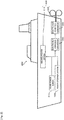
- Fig. 1 is a functional block diagram showing the configuration of a power storage system 100 according to Embodiment 1.
- Fig. 2 schematically shows a ship 300, in which the power storage system 100 is installed.
- the use of the power storage system 100 shown in Fig. 1 is not particularly limited.
- the power storage system 100 is used in a mobile unit such as a vehicle.
- the power storage system 100 is, for example, used as an auxiliary power supply of an electric propulsion ship 300 shown in Fig. 2 .
- electric propulsive force driving force of an electrically-powered generator 330
- a main driving source for a propeller 220 is used as a main driving source for a propeller 220.
- a main engine (not shown) may be used as a main driving source for the propeller 220, and the electric propulsive force (driving force of the electrically-powered generator 330) may be used as an auxiliary driving source for the propeller 220.
- the electrically-powered generator 330 is connected to the power storage system 100, a main power supply 310, and an inboard power system 210 via an electrically-powered converter 320.
- the main power supply 310 installed in the ship 300.
- electric power supply from the main power supply 310 is blocked due to overcurrent.
- the power storage system 100 which serves as an auxiliary power supply, is connected to a load 200 of the ship 300 (the load 200 includes, for example, the inboard power system 210 and the electrically-powered generator 330 for driving the propeller 220).
- the power storage system 100 assists the main power supply 310 as necessary in a manner to supply electric power to the load 200 or receive and store electric power from the load 200. It should be noted that the use of the power storage system 100 is not limited to the auxiliary power supply of the ship 300. As an alternative, the power storage system 100 may be used, for example, as a power storage system for supplying electric power to an automobile or a household.
- the power storage system 100 includes a secondary battery 10, a capacitor 11, and a controller 12.
- the power storage system 100 supplies electric power to the load 200 via a DC/AC inverter 13. Also, the power storage system 100 receives electric power from the load 200, and stores the electric power in one of or both of the secondary battery 10 and the capacitor 11.
- Load-side terminals of the DC/AC inverter (power converter) 13 are connected to the load 200.
- the DC/AC inverter 13 converts DC power inputted to a power-supply-side terminal thereof into AC power, and outputs the AC power from a load-side terminal thereof. Also, the DC/AC inverter 13 converts AC power inputted to a load-side terminal thereof into DC power, and outputs the DC power from a power-supply-side terminal thereof.
- the secondary battery 10 and the capacitor 11, which are parallel to each other, are connected the power-supply-side terminals of the DC/AC inverter 13.
- the capacitor 11 is connected to the power-supply-side terminals of the DC/AC inverter 13 via a DC/DC converter 17.
- the secondary battery 10 is connected to the power-supply-side terminals of the DC/AC inverter 13 via a DC link 20 formed by a pair of wires, and the capacitor 11 is connected to the DC link 20 via the DC/DC converter 17.
- a DC link capacitor 14 is connected between the pair of wires that forms the DC link 20.
- the DC link capacitor 14 smooths voltage fluctuation of the DC link 20.
- a voltage sensor 15 is connected in parallel to the DC link capacitor 14. The voltage sensor 15 detects a DC link voltage Vdc (a voltage between both ends of the DC link capacitor 14), which is a voltage of the DC link 20.
- the secondary battery 10 is a large-capacity electrical storage device that stores electric charge via chemical reaction or physical reaction, and releases the stored electric charge via reverse reaction.
- Examples of the secondary battery 10 include a lithium ion battery, a nickel metal hydride battery, and a lead battery.
- a first current sensor 16 is connected to the secondary battery 10 in series. The first current sensor 16 is provided between the secondary battery 10 and a connection point to the capacitor 11, and detects a current Ib that is discharged from the secondary battery 10 or that charges the secondary battery 10.
- the capacitor 11 is a high power electrical storage device that directly stores electric charge (i.e., without any reaction) and that directly releases the stored electric charge. Examples of the capacitor 11 include a lithium ion capacitor and an electric double layer capacitor.
- the capacitor 11 is connected to the DC link 20 via the DC/DC converter 17. The connection point where the capacitor 11 is connected to the DC link 20 is provided between the first current sensor 16 and the DC link capacitor 14.
- the DC/DC converter 17 causes a change in the current of the capacitor 11 by changing a conduction ratio.
- the DC/DC converter 17 may have a boosting function or step-down function capable of changing the voltage.
- a DC reactor 18 (DCL) is connected in series to the DC/DC converter 17.
- the DC reactor 18 smooths a current that is outputted from the DC/DC converter 17 or that is inputted to the DC/DC converter 17.
- a second current sensor 19 is connected in series to the DC/DC converter 17.
- the second current sensor 19 detects a current Ic that is discharged from the capacitor 11 or that charges the capacitor 11.
- the controller 12 controls the DC/DC converter 17 to prioritize the charging and discharging of the capacitor 11 over the charging and discharging of the secondary battery 10.
- the controller 12 includes a first control unit 12a and a second control unit 12b.
- the first control unit 12a generates a current command value Ic* of the capacitor 11 (a target current value of the capacitor) based on a deviation of the current Ib of the secondary battery 10 from a predetermined current command value Ib* of the secondary battery 10 (a target current value of the secondary battery).
- the second control unit 12b generates a conduction ratio D of the DC/DC converter 17 based on a deviation of the current Ic of the capacitor 11 from the current command value Ic*, and outputs the conduction ratio D to the DC/DC converter 17.
- the controller 12 directly controls the current of the capacitor 11 and indirectly controls the current of the secondary battery 10, and thus the flow of the current in the entire power storage system 100 is controlled.
- the predetermined current command value Ib* herein is set to 0 (zero) or a value close to 0 (zero). Accordingly, when load fluctuation occurs, the current Ib of the secondary battery 10 is restrained to the predetermined current command value Ib*. Therefore, the number of times of charging and discharging of the secondary battery 10 is restrained in accordance with the predetermined current command value Ib*. Consequently, the charging and discharging of the capacitor 11 are prioritized over the charging and discharging of the secondary battery 10.
- the first control unit 12a generates the current command value Ic* of the capacitor 11 based on a current Ibsoc* for keeping the SOC (State Of Charge) (%) of the secondary battery 10 to a predetermined value and a deviation of the current Ib of the secondary battery 10 from the current command value Ib*. In this manner, the flow of the current in the entire power storage system 100 is controlled while restraining the fluctuation of the SOC of the secondary battery 10.
- Fig. 3 is a block diagram showing an example of the configuration of the controller 12 of the power storage system 100.
- the secondary battery 10 is used in a plateau region where its internal electromotive force Eb (V) is flat.
- Eb internal electromotive force
- the secondary battery 10 is used when the SOC is close to 50 %.
- the DC link voltage Vdc (V) applied to the DC link capacitor 14 is equal to the internal electromotive force Eb (V) of the secondary battery 10.
- the internal electromotive force Eb depends on the SOC (State Of Charge) (%) of the secondary battery 10, and is calculated by its function f (SOC (t)).
- the SOC in Equation 1 is represented by Equation 2 below.
- Ib in Equation 2 represents the current (A) of the secondary battery 10
- Qb0 in Equation 2 represents the rated capacity (Ah) of the capacitor 11.
- Eb f SOC t [Math. 1]
- SOC t SOC 0 ⁇ 100.0 Q b 0 ⁇ 0 t I b dt
- a current Icdc (A) flows from the DC link capacitor 14.
- the current Icdc is represented by Equation 4 below.
- Ic represents the current (primary-side current) (A) of the capacitor 11 at the primary-side (DC link capacitor 14 side) of the DC/DC converter 17.
- Icdc Idc ⁇ Ib ⁇ Ic
- Vdc the voltage (DC link voltage) Vdc of the DC link capacitor 14 drops.
- the DC link voltage Vdc is represented by Equation 5 below.
- Cdc represents the capacitance (F) of the DC link capacitor 14.
- Vdc ⁇ 1 / Cdc ⁇ Icdc ⁇ dt
- the first current sensor 16 detects and outputs the current Ib to the controller 12. As shown in Fig. 3 , the controller 12 receives the current Ib from the first current sensor 16, and performs control to prioritize the charging and discharging of the capacitor 11 over the charging and discharging of the secondary battery 10 to supply active power Pac.
- active power Pac (t) (W) is supplied to the load 200 from the secondary battery 10 and the capacitor 11 via the DC/AC inverter 13. Accordingly, as shown in Equation 7 below, the active power Pac (t) is the sum of power Pb (t) (W) of the secondary battery 10 and power Pc (t) (W) of the capacitor 11, and is greater than 0 (W).
- Pac t Pb t + Pc t , t > 0
- the current command value Ib* of the secondary battery 10 target current value of the secondary battery
- the power Pb (t) of the secondary battery 10 is brought close to 0 (W), resulting in a relationship represented by Equation 8 below, and the capacitor 11 is used in priority to the secondary battery 10 such hat the capacitor 11 covers the entire active power Pac (t).
- the current command value Ib* of the secondary battery 10 may be set not 0 (A) but to a value (A) close to 0 (zero), so long as the capacitor 11 is used in priority to the secondary battery 10.
- Pac t Pc t , t > 0
- the first control unit 12a calculates an output power command value Pc* (W) of the capacitor 11 from a deviation (Ib* - Ib) of the current Ib received from the first current sensor 16, which is a deviation from the current command value Ib* of the secondary battery 10.
- C1 (s) represents a transfer function.
- Pc ⁇ C 1 s ⁇ Ib ⁇ ⁇ Ib
- the first control unit 12a obtains the DC link voltage Vdc from the voltage sensor 15. Then, the first control unit 12a performs arithmetic operation in accordance with Equation 10 below to obtain the current command value Ic* of the capacitor 11 (target current value of the capacitor) from the DC link voltage Vdc and the output power command value Pc* obtained by Equation 9.
- the primary-side current command value Ic* is a current command value (A) of the capacitor 11 at the primary side (DC link capacitor 14 side) of the DC/DC converter 17.
- Ic ⁇ Pc ⁇ / Vdc
- the second control unit 12b obtains the current Ic of the capacitor 11 from the second current sensor 19. Then, based on Equation 11 below, the second control unit 12b calculates the conduction ratio D of the DC/DC converter 17 from a deviation (Ic* - Ic) of the current Ic from the primary-side current command value Ic*.
- C2 (s) represents a transfer function.
- D C 2 s ⁇ Ic ⁇ ⁇ Ic
- the current command value Ib* of the secondary battery 10 is set to 0 (zero) or a value close to 0 (zero). Accordingly, the power Pc of the capacitor 11 is supplied to the load 200 as active power Pac. If the power Pc of the capacitor 11 is equal to the active power Pac, it means that the power Pc of the capacitor 11 is sufficient as the active power Pac. In this case, electric power is supplied to the load 200 only by the capacitor 11.
- the power Pc of the capacitor 11 is less than the active power Pac due to, for example, a decrease in the SOC of the capacitor 11 and/or limitation of the output current of the capacitor 11, then the power Pc of the capacitor 11 is insufficient as the active power Pac.
- the DC link voltage Vdc decreases, causing a potential difference between the DC link voltage Vdc and the internal electromotive force Eb. Consequently, a discharge current Ib (A) flows from the secondary battery 10 to the DC link capacitor 14, and power Pb of the secondary battery 10 as in Equation 13 below is supplied to the DC link capacitor 14. Electric power that is the sum of the power Pb of the secondary battery 10 and the power Pc of the capacitor 11 is supplied to the load 200 as the active power Pac.
- Pb Vdc ⁇ Ib
- the current command value Ibsoc* may be alternatively added to the deviation of the current Ib from the current command value Ib*.
- the current of the capacitor 11 is controlled based on the conduction ratio of the DC/DC converter 17, and thereby the current of the secondary battery 10 can be indirectly controlled and the flow of the current in the entire power storage system 100 can be controlled. Accordingly, the control parameters do not depend on load fluctuation characteristics, and thus the power storage system 100 is excellent in terms of versatility.
- the charging and discharging of the capacitor 11 are prioritized over the charging and discharging of the secondary battery 10. As a result, the number of times of charging and discharging and the depth of charge and discharge of the secondary battery 10 can be reduced, which makes it possible to extend the life of the secondary battery 10.
- the current command value Ib* of the secondary battery 10 is set to 0 or a value close to 0. In this manner, the charging and discharging of the capacitor 11 can be readily prioritized over the charging and discharging of the secondary battery 10.
- the current command value Ib* of the secondary battery 10 may be set to a value close to 0 (zero), for example, to a current value that is less than or equal to the one-hour current rate of the secondary battery 10.
- the "one-hour current rate” herein refers to a current value that allows the secondary battery to be charged from 0 % to 100 % of SOC (State Of Charge) in one hour, or a current value that allows the secondary battery to discharge from 100 % to 0 % of SOC in one hour.
- the charge/discharge current Ib of the secondary battery 10 is limited to be less than or equal to the one-hour current rate (1C). This makes it possible to suppress the advancement of degradation of the secondary battery 10, the advancement of degradation being caused when a current flowing through the secondary battery 10 is greater than a current flowing through the capacitor 11, and thereby the life of the secondary battery 10 can be extended.
- the load sharing ratio of the secondary battery 10 to the capacitor 11 is k : (1-k). Accordingly, the load sharing ratio of the secondary battery 10 can be adjusted by the proportionality coefficient k.
- the charge/discharge current Ib of the secondary battery 10 can be increased by reducing the current command value Ic* of the capacitor 11.
- the life of the secondary battery 10 depends on the amount of heat generated the secondary battery 10. The greater the amount of heat generated by the secondary battery 10, the more the secondary battery 10 degrades and the shorter the life of the secondary battery 10 becomes. Therefore, the life of the secondary battery 10 was evaluated based on the amount of heat generated by the secondary battery 10 when the power storage system 100 was controlled in accordance with a charge/discharge pattern.
- the current command value ib* of the secondary battery 10 was set to 0 as in the example of control shown in Fig. 3 , and the current of the capacitor 11 was controlled by the conduction ratio D of the DC/DC converter 17 calculated based on detection values Ib, Ic, and Vdc from the sensors 16, 19, and 15.
- a proportional compensator was used similar to the hybrid power supply system of Non-Patent Literature 1 described above, and a high-frequency component was separated by using a HPF (High Pass Filter), such that a low-frequency component of electric power was supplied by the secondary battery 10 and a high-frequency component of electric power was supplied by the electric double layer capacitor 11.
- the time constant T EDLC of the HPF was set to be greater than the cycle of a charge/discharge pattern
- the proportional gain kp of the proportional compensator was set to a small value that is in such a range as not to reach the upper limit voltage and the lower limit voltage of the capacitor 11. Accordingly, the time constant T EDLC and the proportional gain kp vary in accordance with the cycle of the charge/discharge pattern and the voltage.
- the configuration (the number of secondary batteries 10, the number of capacitors 11, each internal resistance, capacitance, etc.), the method of controlling the DC/DC converter 17, and the parameters were the same between the power storage system 100 of the working example and the power supply system of the comparative example.
- the capacity of the secondary battery 10 was set to 155.52 kWh so that a loss in the capacitor 11 could be sufficiently compensated for.
- the initial power amount of the capacitor 11 was set to 2.15 kWh.
- the power storage system 100 of the working example and the power supply system of the comparative example were controlled in accordance with two different types of charge/discharge patterns between which the magnitude of electric power and the charge/discharge frequency were different. Since a loss (internal loss) in the secondary battery 10 is entirely or substantially entirely converted into thermal energy, a loss amount Loss (kWh) was calculated as the amount of generated heat by Equation 15 shown below.
- Equation 15 i represents the current (A) of the secondary battery 10
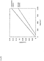
- a first charge/discharge pattern electric power of 250 kW was discharged for five seconds (0.347 kWh). Then, after an interval of one second, electric power of 250 kW was charged for five seconds, followed by an interval of one second. This charge/discharge cycle of 12 seconds was repeated.
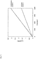
- a second charge/discharge pattern electric power of 500 kW was discharged for fifteen seconds (2.083 kWh). Then, after an interval of two seconds, electric power of 500 kW was charged for fifteen seconds, followed by an interval of two seconds. This charge/discharge cycle of 34 seconds was repeated.
- the first charge/discharge pattern can be called light charge/discharge relative to the capacitor 11.
- the second charge/discharge pattern can be called heavy charge/discharge relative to the capacitor 11.
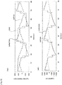
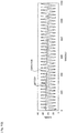
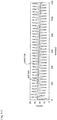
- the verification results indicate that when charged and discharged in the first charge/discharge pattern, the loss amount Loss increased in both the working example and the comparative example in accordance with the elapse of time.
- the loss amount Loss increased in both the working example and the comparative example in accordance with the elapse of time.
- the loss amount in the working example was less than the loss amount in the comparative example, and the difference between the loss amount in the working example and the loss amount in the comparative example increased in accordance with the elapse of time.
- the loss amount in the working example was 72.2 % of the loss amount in the comparative example.
- the loss amount in the working example was 51.3 % of the loss amount in the comparative example.
- the loss amount in the working example was less than the loss amount in the comparative example. Therefore, the amount of generated heat in the working example was less than the amount of generated heat in the comparative example. For this reason, it can be considered that, in the working example, thermal degradation of the secondary battery 10 was reduced, and thus the life of the secondary battery 10 was extended.
- the difference between the loss amount in the working example and the loss amount in the comparative example as described above is derived from the electric power (kWh) of the secondary battery 10 and the current (A) of the secondary battery 10.
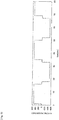
- the electric power (kWh) of the secondary battery 10 when charged and discharged in the second charge/discharge pattern in the working example, electric power is supplied only from the capacitor 11 at the start of discharging to the load 200. Accordingly, in accordance with a decrease in the SOC of the capacitor 11, electric power also starts to be supplied from the secondary battery 10. Next, while the system is not in operation, the supply of electric power from the secondary battery 10 ends, and during charging, electric power is supplied only to the capacitor 11.
- the current flows only from the capacitor 11 at the initial stage of the discharging, and in accordance with a decrease in the SOC of the capacitor 11, the current also starts to flow from the secondary battery 10. While the system is not in operation, the flow of the current from the secondary battery 10 ends, and during charging, the current flows only to the capacitor 11.
- FIG. 9A are also applied to the current shown in Fig. 9B .
- the current flows only from the capacitor 11 at the initial stage of the discharging, and thereafter, the current flows also from the secondary battery 10. While the system is not in operation and until the middle stage of the charging, the current flows from the secondary battery 10. During the charging, the current flows to the capacitor 11. From the middle stage of the charging, the current also flows to the secondary battery 10.
- the SOC of the capacitor 11 rapidly increases and decreases due to the function of the HPF, and in response, the proportional compensator operates to compensate for the power command value of the capacitor 11. Accordingly, the current of the secondary battery 10 always flows not only during discharging but also during charging.
- the current command value ib* of the secondary battery 10 is set to 0 (A), and thereby the output power command value Pc* of the capacitor 11 corresponding to the deviation of the current Ib of the secondary battery 10 from the current command value ib* is determined. Accordingly, no electric power from the secondary battery 10 is supplied to the capacitor 11. In this manner, in the working example, electric power is efficiently charged only to the capacitor 11. Thus, exchange of electric power between the secondary battery 10 and the capacitor 11 as in the comparative example is not performed in the working example. Consequently, in the working example, the loss amount (the amount of generated heat) is less than in the comparative example.
- the SOC (%) of the secondary battery 10 was 38.9 %.
- the SOC (%) of the secondary battery 10 was 37.5 %.
- the SOC of the secondary battery 10 of the working example was substantially the same as the SOC of the secondary battery 10 of the comparative example. It should be noted that, in both the working example and the comparative example, the SOC of the secondary battery 10 was 50 % at the start of charging/discharging.
- a DC/DC converter may be used as the power converter in place of the DC/AC inverter 13.
- the power storage system and the method of controlling the same according to the present invention are useful, for example, as a highly versatile and long-lived power storage system and a method of controlling the same.
Landscapes
- Engineering & Computer Science (AREA)
- Power Engineering (AREA)
- Charge And Discharge Circuits For Batteries Or The Like (AREA)
- Secondary Cells (AREA)
Claims (3)
- Stromspeichersystem, welches aufweist:einen Stromkonverter (13), dessen lastseitige Anschlüsse mit einer Last verbunden sind;eine sekundäre Batterie (10), die mit stromversorgungsseitigen Anschlüssen des Stromkonverters verbunden ist;ein Kondensator (11), der mit den stromversorgungsseitigen Anschlüssen des Stromkonverters über einen DC/DC-Konverter (17) parallel zur sekundären Batterie verbunden ist, undgekennzeichnet durcheine Steuerung (12), die ausgestaltet ist, den DC/DC-Konverter zu steuern, um Laden und Entladen des Kondensators gegenüber Laden und Entladen der sekundären Batterie zu priorisieren, wobei die Steuerung umfasst:eine erste Steuereinheit (12a), die ausgestaltet ist, einen Stromsollwert des Kondensators basierend auf einer Abweichung von einen Strom der sekundären Batterie von einem vorbestimmten Stromsollwert der sekundären Batterie zu generieren, wobei der vorbestimmte Stromsollwert Null oder nahezu Null ist; undeine zweite Steuereinheit (12b), die ausgestaltet ist, ein Leitungsverhältnis des DC/DC-Konverters basierend auf einer Abweichung von einem Strom des Kondensators von dem Stromsollwert des Kondensators zu generieren, und das Leitungsverhältnis an den DC/DC-Konverter auszugeben, undwobei der vorbestimmte Stromsollwert der sekundären Batterie, der vorbestimmte Stromsollwert nahezu Null, ein Stromwert ist, der kleiner oder gleich einer Ein-Stunden-Stromrate der sekundären Batterie ist.
- Stromspeichersystem nach Anspruch 1, wobei
die erste Steuereinheit (12a) ausgestaltet ist, den Stromsollwert des Kondensators basierend auf einem Strom zum Halten von SOC der sekundären Batterie bei einem vorbestimmten Wert und die Abweichung des Stroms der sekundären Batterie von dem vorbestimmten Stromsollwert der zweiten Batterie zu generieren. - Verfahren zum Steuern eines Stromspeichersystems, wobei das Stromspeichersystem umfasst:einen Stromkonverter (13), dessen lastseitige Anschlüsse mit einer Last verbunden sind;eine sekundäre Batterie (10), die mit stromversorgungsseitigen Anschlüssen des Stromkonverters verbunden ist;einen Kondensator (11), der an die stromversorgungsseitigen Anschlüsse des Stromkonverter über einen DC/DC-Konverter (17) parallel zu der sekundären Batterie verbunden ist; undeine Steuerung (12),wobei das Verfahren durch folgende Schritte gekennzeichnet ist:Erzeugen, durch eine Steuerung, eines Stromsollwerts des Kondensators basierend auf einer Abweichung eines Stroms der sekundären Batterie von einem vorbestimmten Stromsollwert der sekundären Batterie, wobei der vorbestimmte Stromsollwert Null oder nahezu Null ist;Erzeugen, durch eine Steuerung, eines Leitungsverhältnisses des DC/DC-Konverters basierend auf einer Abweichung eines Stroms des Kondensators von dem Stromsollwert des Kondensators, und Ausgeben des Leitungsverhältnisses an den DC/DC-Konverter; undSteuerung des DC/DC-Konverters durch die Steuerung, um Laden und Entladen des Kondensators gegenüber Laden und Entladen der zweiten Batterie zu priorisieren,wobei der vorbestimmte Stromsollwert der sekundären Batterie, der vorbestimmte Stromsollwert nahezu Null, ein Stromwert ist, der kleiner oder gleich einer Ein-Stunden-Stromrate der sekundären Batterie ist.
Applications Claiming Priority (2)
| Application Number | Priority Date | Filing Date | Title |
|---|---|---|---|
| JP2014120288A JP6496496B2 (ja) | 2014-06-11 | 2014-06-11 | 電力貯蔵システムおよびその制御方法 |
| PCT/JP2015/002905 WO2015190094A1 (ja) | 2014-06-11 | 2015-06-10 | 電力貯蔵システムおよびその制御方法 |
Publications (3)
| Publication Number | Publication Date |
|---|---|
| EP3157132A1 EP3157132A1 (de) | 2017-04-19 |
| EP3157132A4 EP3157132A4 (de) | 2018-02-21 |
| EP3157132B1 true EP3157132B1 (de) | 2019-11-20 |
Family
ID=54833205
Family Applications (1)
| Application Number | Title | Priority Date | Filing Date |
|---|---|---|---|
| EP15806373.5A Active EP3157132B1 (de) | 2014-06-11 | 2015-06-10 | Hybrides stromspeichersystem und verfahren zur steuerung davon |
Country Status (6)
| Country | Link |
|---|---|
| US (1) | US10263448B2 (de) |
| EP (1) | EP3157132B1 (de) |
| JP (1) | JP6496496B2 (de) |
| CN (1) | CN106464000B (de) |
| CA (1) | CA2916461C (de) |
| WO (1) | WO2015190094A1 (de) |
Families Citing this family (11)
| Publication number | Priority date | Publication date | Assignee | Title |
|---|---|---|---|---|
| JP6781550B2 (ja) * | 2016-02-01 | 2020-11-04 | 川崎重工業株式会社 | 電力貯蔵システムおよびその制御方法 |
| JP2017139844A (ja) | 2016-02-01 | 2017-08-10 | 川崎重工業株式会社 | 電力貯蔵装置 |
| TWM538649U (zh) * | 2016-02-04 | 2017-03-21 | Kai Si Rong Co Ltd | 具高儲電效能電容之電源裝置 |
| CN105703435B (zh) * | 2016-03-22 | 2019-06-11 | 深圳市德利和能源技术有限公司 | 储能系统 |
| US10854866B2 (en) | 2019-04-08 | 2020-12-01 | H55 Sa | Power supply storage and fire management in electrically-driven aircraft |
| US10479223B2 (en) * | 2018-01-25 | 2019-11-19 | H55 Sa | Construction and operation of electric or hybrid aircraft |
| US11063323B2 (en) | 2019-01-23 | 2021-07-13 | H55 Sa | Battery module for electrically-driven aircraft |
| US11148819B2 (en) | 2019-01-23 | 2021-10-19 | H55 Sa | Battery module for electrically-driven aircraft |
| US11065979B1 (en) | 2017-04-05 | 2021-07-20 | H55 Sa | Aircraft monitoring system and method for electric or hybrid aircrafts |
| EP3743974A1 (de) * | 2018-01-25 | 2020-12-02 | H55 Sa | Stromversorgungs- oder antriebssystem für einen motor in einem elektrisch angetriebenen flugzeug |
| CN112533822B (zh) * | 2018-08-31 | 2023-10-10 | 川崎重工业株式会社 | 电池电气推进船供电系统、海上供电设备以及电池电气推进船 |
Family Cites Families (12)
| Publication number | Priority date | Publication date | Assignee | Title |
|---|---|---|---|---|
| JP3430709B2 (ja) * | 1995-04-28 | 2003-07-28 | いすゞ自動車株式会社 | 電気自動車電源制御装置 |
| JP2900309B2 (ja) * | 1996-08-30 | 1999-06-02 | 日晴金属株式会社 | 電動車の回生システム |
| JP2002095174A (ja) * | 2000-09-13 | 2002-03-29 | Casio Comput Co Ltd | 電源装置及びその充放電方法 |
| US7791216B2 (en) * | 2004-11-01 | 2010-09-07 | Ford Global Technologies, Llc | Method and system for use with a vehicle electric storage system |
| JP4866764B2 (ja) * | 2007-03-12 | 2012-02-01 | 清水建設株式会社 | 分散型電源の制御方法 |
| EP2173018A1 (de) * | 2007-07-25 | 2010-04-07 | Panasonic Corporation | Stromquellenvorrichtung für ein fahrzeug |
| JP2010288414A (ja) * | 2009-06-15 | 2010-12-24 | Toyota Motor Corp | 車両の電源装置 |
| JP5189607B2 (ja) * | 2010-02-04 | 2013-04-24 | トヨタ自動車株式会社 | 車両用電源装置 |
| JP5318004B2 (ja) * | 2010-03-01 | 2013-10-16 | 三菱電機株式会社 | 車両用電源システム |
| CN103052527B (zh) * | 2010-08-02 | 2015-02-11 | 松下电器产业株式会社 | 车辆用电源装置 |
| JP2014060890A (ja) * | 2012-09-19 | 2014-04-03 | Kuzumi Denshi Kogyo Kk | 電源装置 |
| EP2919370B1 (de) | 2012-11-07 | 2020-12-30 | Volvo Truck Corporation | Stromquellenvorrichtung |
-
2014
- 2014-06-11 JP JP2014120288A patent/JP6496496B2/ja active Active
-
2015
- 2015-06-10 CN CN201580030874.4A patent/CN106464000B/zh active Active
- 2015-06-10 WO PCT/JP2015/002905 patent/WO2015190094A1/ja active Application Filing
- 2015-06-10 CA CA2916461A patent/CA2916461C/en active Active
- 2015-06-10 EP EP15806373.5A patent/EP3157132B1/de active Active
- 2015-06-10 US US15/318,304 patent/US10263448B2/en active Active
Non-Patent Citations (1)
| Title |
|---|
| None * |
Also Published As
| Publication number | Publication date |
|---|---|
| EP3157132A4 (de) | 2018-02-21 |
| CA2916461A1 (en) | 2015-12-17 |
| JP6496496B2 (ja) | 2019-04-03 |
| JP2016001936A (ja) | 2016-01-07 |
| US10263448B2 (en) | 2019-04-16 |
| WO2015190094A1 (ja) | 2015-12-17 |
| CA2916461C (en) | 2016-11-01 |
| EP3157132A1 (de) | 2017-04-19 |
| CN106464000B (zh) | 2019-04-16 |
| US20170126025A1 (en) | 2017-05-04 |
| CN106464000A (zh) | 2017-02-22 |
Similar Documents
| Publication | Publication Date | Title |
|---|---|---|
| EP3157132B1 (de) | Hybrides stromspeichersystem und verfahren zur steuerung davon | |
| US9975447B2 (en) | Temperature control apparatus for electricity storage device for use in electricity storage system including electricity storage devices | |
| EP1983349B1 (de) | Einrichtung zur schätzung der restkapazität einer sekundärzelle und verfahren zur schätzung der restkapazität | |
| JP5381026B2 (ja) | 複合電源装置の制御回路 | |
| US11196103B2 (en) | Secondary battery system and method for controlling secondary battery | |
| WO2018198668A1 (ja) | 電力供給装置、蓄電システム、及び充電方法 | |
| US9520736B2 (en) | Charging control apparatus and charging control method for secondary battery | |
| US9263906B2 (en) | Control apparatus and control method for lithium-ion secondary battery | |
| JP5488097B2 (ja) | 電流推定装置およびdcdcコンバータ制御システム | |
| US9956888B2 (en) | Power supply system | |
| US10305392B2 (en) | Conversion apparatus, equipment, and control method | |
| JP6220904B2 (ja) | 蓄電装置 | |
| US10576835B2 (en) | Energy storage device, transport apparatus, and control method | |
| EP2662921B1 (de) | Lade- und entladevorrichtung | |
| JP2017112729A (ja) | バッテリ制御システム | |
| JP6624035B2 (ja) | 電池システム | |
| JP6699533B2 (ja) | 電池システム | |
| JP2016152718A (ja) | 充放電制御装置、移動体及び電力分担量決定方法 | |
| JP7337482B2 (ja) | 電源装置 | |
| JP2013038832A (ja) | 二次電池の充電システム | |
| JP2019102136A (ja) | 燃料電池システム | |
| JP6611118B2 (ja) | 電力変換装置およびそれを用いた産業機械 | |
| JP2017084636A (ja) | 電池制御装置 | |
| JP5418417B2 (ja) | 二次電池の充電制御方法及び充電制御装置 | |
| JP2015211608A (ja) | 電力変換ユニットおよび電力変換時のリプル抑制制御方法 |
Legal Events
| Date | Code | Title | Description |
|---|---|---|---|
| STAA | Information on the status of an ep patent application or granted ep patent |
Free format text: STATUS: THE INTERNATIONAL PUBLICATION HAS BEEN MADE |
|
| PUAI | Public reference made under article 153(3) epc to a published international application that has entered the european phase |
Free format text: ORIGINAL CODE: 0009012 |
|
| STAA | Information on the status of an ep patent application or granted ep patent |
Free format text: STATUS: REQUEST FOR EXAMINATION WAS MADE |
|
| 17P | Request for examination filed |
Effective date: 20170111 |
|
| AK | Designated contracting states |
Kind code of ref document: A1 Designated state(s): AL AT BE BG CH CY CZ DE DK EE ES FI FR GB GR HR HU IE IS IT LI LT LU LV MC MK MT NL NO PL PT RO RS SE SI SK SM TR |
|
| AX | Request for extension of the european patent |
Extension state: BA ME |
|
| DAV | Request for validation of the european patent (deleted) | ||
| DAX | Request for extension of the european patent (deleted) | ||
| A4 | Supplementary search report drawn up and despatched |
Effective date: 20180123 |
|
| RIC1 | Information provided on ipc code assigned before grant |
Ipc: H02J 7/34 20060101AFI20180117BHEP Ipc: H02J 1/10 20060101ALI20180117BHEP Ipc: H02J 7/14 20060101ALI20180117BHEP |
|
| GRAP | Despatch of communication of intention to grant a patent |
Free format text: ORIGINAL CODE: EPIDOSNIGR1 |
|
| STAA | Information on the status of an ep patent application or granted ep patent |
Free format text: STATUS: GRANT OF PATENT IS INTENDED |
|
| INTG | Intention to grant announced |
Effective date: 20190520 |
|
| RIN1 | Information on inventor provided before grant (corrected) |
Inventor name: TOKUSHIGE, TAKAYUKI Inventor name: OHNO, TATSUYA Inventor name: KATAOKA, MIKIHIKO Inventor name: BANDO, SOICHIRO Inventor name: HAYASHI, MASATO |
|
| GRAS | Grant fee paid |
Free format text: ORIGINAL CODE: EPIDOSNIGR3 |
|
| GRAA | (expected) grant |
Free format text: ORIGINAL CODE: 0009210 |
|
| STAA | Information on the status of an ep patent application or granted ep patent |
Free format text: STATUS: THE PATENT HAS BEEN GRANTED |
|
| AK | Designated contracting states |
Kind code of ref document: B1 Designated state(s): AL AT BE BG CH CY CZ DE DK EE ES FI FR GB GR HR HU IE IS IT LI LT LU LV MC MK MT NL NO PL PT RO RS SE SI SK SM TR |
|
| REG | Reference to a national code |
Ref country code: GB Ref legal event code: FG4D |
|
| RIN1 | Information on inventor provided before grant (corrected) |
Inventor name: KATAOKA, MIKIHIKO Inventor name: HAYASHI, MASATO Inventor name: BANDO, SOICHIRO Inventor name: OHNO, TATSUYA Inventor name: TOKUSHIGE, TAKAYUKI |
|
| REG | Reference to a national code |
Ref country code: CH Ref legal event code: EP |
|
| REG | Reference to a national code |
Ref country code: IE Ref legal event code: FG4D |
|
| REG | Reference to a national code |
Ref country code: DE Ref legal event code: R096 Ref document number: 602015042191 Country of ref document: DE |
|
| REG | Reference to a national code |
Ref country code: AT Ref legal event code: REF Ref document number: 1205296 Country of ref document: AT Kind code of ref document: T Effective date: 20191215 |
|
| REG | Reference to a national code |
Ref country code: NO Ref legal event code: T2 Effective date: 20191120 |
|
| REG | Reference to a national code |
Ref country code: NL Ref legal event code: MP Effective date: 20191120 |
|
| REG | Reference to a national code |
Ref country code: LT Ref legal event code: MG4D |
|
| PG25 | Lapsed in a contracting state [announced via postgrant information from national office to epo] |
Ref country code: FI Free format text: LAPSE BECAUSE OF FAILURE TO SUBMIT A TRANSLATION OF THE DESCRIPTION OR TO PAY THE FEE WITHIN THE PRESCRIBED TIME-LIMIT Effective date: 20191120 Ref country code: BG Free format text: LAPSE BECAUSE OF FAILURE TO SUBMIT A TRANSLATION OF THE DESCRIPTION OR TO PAY THE FEE WITHIN THE PRESCRIBED TIME-LIMIT Effective date: 20200220 Ref country code: NL Free format text: LAPSE BECAUSE OF FAILURE TO SUBMIT A TRANSLATION OF THE DESCRIPTION OR TO PAY THE FEE WITHIN THE PRESCRIBED TIME-LIMIT Effective date: 20191120 Ref country code: SE Free format text: LAPSE BECAUSE OF FAILURE TO SUBMIT A TRANSLATION OF THE DESCRIPTION OR TO PAY THE FEE WITHIN THE PRESCRIBED TIME-LIMIT Effective date: 20191120 Ref country code: LV Free format text: LAPSE BECAUSE OF FAILURE TO SUBMIT A TRANSLATION OF THE DESCRIPTION OR TO PAY THE FEE WITHIN THE PRESCRIBED TIME-LIMIT Effective date: 20191120 Ref country code: GR Free format text: LAPSE BECAUSE OF FAILURE TO SUBMIT A TRANSLATION OF THE DESCRIPTION OR TO PAY THE FEE WITHIN THE PRESCRIBED TIME-LIMIT Effective date: 20200221 Ref country code: LT Free format text: LAPSE BECAUSE OF FAILURE TO SUBMIT A TRANSLATION OF THE DESCRIPTION OR TO PAY THE FEE WITHIN THE PRESCRIBED TIME-LIMIT Effective date: 20191120 |
|
| PG25 | Lapsed in a contracting state [announced via postgrant information from national office to epo] |
Ref country code: IS Free format text: LAPSE BECAUSE OF FAILURE TO SUBMIT A TRANSLATION OF THE DESCRIPTION OR TO PAY THE FEE WITHIN THE PRESCRIBED TIME-LIMIT Effective date: 20200320 Ref country code: HR Free format text: LAPSE BECAUSE OF FAILURE TO SUBMIT A TRANSLATION OF THE DESCRIPTION OR TO PAY THE FEE WITHIN THE PRESCRIBED TIME-LIMIT Effective date: 20191120 Ref country code: RS Free format text: LAPSE BECAUSE OF FAILURE TO SUBMIT A TRANSLATION OF THE DESCRIPTION OR TO PAY THE FEE WITHIN THE PRESCRIBED TIME-LIMIT Effective date: 20191120 |
|
| PG25 | Lapsed in a contracting state [announced via postgrant information from national office to epo] |
Ref country code: AL Free format text: LAPSE BECAUSE OF FAILURE TO SUBMIT A TRANSLATION OF THE DESCRIPTION OR TO PAY THE FEE WITHIN THE PRESCRIBED TIME-LIMIT Effective date: 20191120 |
|
| PG25 | Lapsed in a contracting state [announced via postgrant information from national office to epo] |
Ref country code: EE Free format text: LAPSE BECAUSE OF FAILURE TO SUBMIT A TRANSLATION OF THE DESCRIPTION OR TO PAY THE FEE WITHIN THE PRESCRIBED TIME-LIMIT Effective date: 20191120 Ref country code: PT Free format text: LAPSE BECAUSE OF FAILURE TO SUBMIT A TRANSLATION OF THE DESCRIPTION OR TO PAY THE FEE WITHIN THE PRESCRIBED TIME-LIMIT Effective date: 20200412 Ref country code: DK Free format text: LAPSE BECAUSE OF FAILURE TO SUBMIT A TRANSLATION OF THE DESCRIPTION OR TO PAY THE FEE WITHIN THE PRESCRIBED TIME-LIMIT Effective date: 20191120 Ref country code: ES Free format text: LAPSE BECAUSE OF FAILURE TO SUBMIT A TRANSLATION OF THE DESCRIPTION OR TO PAY THE FEE WITHIN THE PRESCRIBED TIME-LIMIT Effective date: 20191120 Ref country code: RO Free format text: LAPSE BECAUSE OF FAILURE TO SUBMIT A TRANSLATION OF THE DESCRIPTION OR TO PAY THE FEE WITHIN THE PRESCRIBED TIME-LIMIT Effective date: 20191120 Ref country code: CZ Free format text: LAPSE BECAUSE OF FAILURE TO SUBMIT A TRANSLATION OF THE DESCRIPTION OR TO PAY THE FEE WITHIN THE PRESCRIBED TIME-LIMIT Effective date: 20191120 |
|
| REG | Reference to a national code |
Ref country code: AT Ref legal event code: MK05 Ref document number: 1205296 Country of ref document: AT Kind code of ref document: T Effective date: 20191120 |
|
| REG | Reference to a national code |
Ref country code: DE Ref legal event code: R097 Ref document number: 602015042191 Country of ref document: DE |
|
| PG25 | Lapsed in a contracting state [announced via postgrant information from national office to epo] |
Ref country code: SM Free format text: LAPSE BECAUSE OF FAILURE TO SUBMIT A TRANSLATION OF THE DESCRIPTION OR TO PAY THE FEE WITHIN THE PRESCRIBED TIME-LIMIT Effective date: 20191120 Ref country code: SK Free format text: LAPSE BECAUSE OF FAILURE TO SUBMIT A TRANSLATION OF THE DESCRIPTION OR TO PAY THE FEE WITHIN THE PRESCRIBED TIME-LIMIT Effective date: 20191120 |
|
| PLBE | No opposition filed within time limit |
Free format text: ORIGINAL CODE: 0009261 |
|
| STAA | Information on the status of an ep patent application or granted ep patent |
Free format text: STATUS: NO OPPOSITION FILED WITHIN TIME LIMIT |
|
| 26N | No opposition filed |
Effective date: 20200821 |
|
| PG25 | Lapsed in a contracting state [announced via postgrant information from national office to epo] |
Ref country code: AT Free format text: LAPSE BECAUSE OF FAILURE TO SUBMIT A TRANSLATION OF THE DESCRIPTION OR TO PAY THE FEE WITHIN THE PRESCRIBED TIME-LIMIT Effective date: 20191120 Ref country code: SI Free format text: LAPSE BECAUSE OF FAILURE TO SUBMIT A TRANSLATION OF THE DESCRIPTION OR TO PAY THE FEE WITHIN THE PRESCRIBED TIME-LIMIT Effective date: 20191120 Ref country code: PL Free format text: LAPSE BECAUSE OF FAILURE TO SUBMIT A TRANSLATION OF THE DESCRIPTION OR TO PAY THE FEE WITHIN THE PRESCRIBED TIME-LIMIT Effective date: 20191120 |
|
| REG | Reference to a national code |
Ref country code: DE Ref legal event code: R119 Ref document number: 602015042191 Country of ref document: DE |
|
| PG25 | Lapsed in a contracting state [announced via postgrant information from national office to epo] |
Ref country code: IT Free format text: LAPSE BECAUSE OF FAILURE TO SUBMIT A TRANSLATION OF THE DESCRIPTION OR TO PAY THE FEE WITHIN THE PRESCRIBED TIME-LIMIT Effective date: 20191120 Ref country code: MC Free format text: LAPSE BECAUSE OF FAILURE TO SUBMIT A TRANSLATION OF THE DESCRIPTION OR TO PAY THE FEE WITHIN THE PRESCRIBED TIME-LIMIT Effective date: 20191120 |
|
| REG | Reference to a national code |
Ref country code: CH Ref legal event code: PL |
|
| GBPC | Gb: european patent ceased through non-payment of renewal fee |
Effective date: 20200610 |
|
| PG25 | Lapsed in a contracting state [announced via postgrant information from national office to epo] |
Ref country code: LU Free format text: LAPSE BECAUSE OF NON-PAYMENT OF DUE FEES Effective date: 20200610 |
|
| REG | Reference to a national code |
Ref country code: BE Ref legal event code: MM Effective date: 20200630 |
|
| PG25 | Lapsed in a contracting state [announced via postgrant information from national office to epo] |
Ref country code: FR Free format text: LAPSE BECAUSE OF NON-PAYMENT OF DUE FEES Effective date: 20200630 Ref country code: LI Free format text: LAPSE BECAUSE OF NON-PAYMENT OF DUE FEES Effective date: 20200630 Ref country code: CH Free format text: LAPSE BECAUSE OF NON-PAYMENT OF DUE FEES Effective date: 20200630 Ref country code: GB Free format text: LAPSE BECAUSE OF NON-PAYMENT OF DUE FEES Effective date: 20200610 Ref country code: IE Free format text: LAPSE BECAUSE OF NON-PAYMENT OF DUE FEES Effective date: 20200610 |
|
| PG25 | Lapsed in a contracting state [announced via postgrant information from national office to epo] |
Ref country code: BE Free format text: LAPSE BECAUSE OF NON-PAYMENT OF DUE FEES Effective date: 20200630 Ref country code: DE Free format text: LAPSE BECAUSE OF NON-PAYMENT OF DUE FEES Effective date: 20210101 |
|
| PG25 | Lapsed in a contracting state [announced via postgrant information from national office to epo] |
Ref country code: TR Free format text: LAPSE BECAUSE OF FAILURE TO SUBMIT A TRANSLATION OF THE DESCRIPTION OR TO PAY THE FEE WITHIN THE PRESCRIBED TIME-LIMIT Effective date: 20191120 Ref country code: MT Free format text: LAPSE BECAUSE OF FAILURE TO SUBMIT A TRANSLATION OF THE DESCRIPTION OR TO PAY THE FEE WITHIN THE PRESCRIBED TIME-LIMIT Effective date: 20191120 Ref country code: CY Free format text: LAPSE BECAUSE OF FAILURE TO SUBMIT A TRANSLATION OF THE DESCRIPTION OR TO PAY THE FEE WITHIN THE PRESCRIBED TIME-LIMIT Effective date: 20191120 |
|
| PG25 | Lapsed in a contracting state [announced via postgrant information from national office to epo] |
Ref country code: MK Free format text: LAPSE BECAUSE OF FAILURE TO SUBMIT A TRANSLATION OF THE DESCRIPTION OR TO PAY THE FEE WITHIN THE PRESCRIBED TIME-LIMIT Effective date: 20191120 |
|
| PGFP | Annual fee paid to national office [announced via postgrant information from national office to epo] |
Ref country code: NO Payment date: 20230608 Year of fee payment: 9 |