EP3156566A1 - Kraftfahrzeugschlüssel - Google Patents
Kraftfahrzeugschlüssel Download PDFInfo
- Publication number
- EP3156566A1 EP3156566A1 EP16186918.5A EP16186918A EP3156566A1 EP 3156566 A1 EP3156566 A1 EP 3156566A1 EP 16186918 A EP16186918 A EP 16186918A EP 3156566 A1 EP3156566 A1 EP 3156566A1
- Authority
- EP
- European Patent Office
- Prior art keywords
- key
- securing device
- securing
- housing
- motor vehicle
- Prior art date
- Legal status (The legal status is an assumption and is not a legal conclusion. Google has not performed a legal analysis and makes no representation as to the accuracy of the status listed.)
- Granted
Links
- 238000003780 insertion Methods 0.000 claims description 9
- 230000037431 insertion Effects 0.000 claims description 9
- 230000000694 effects Effects 0.000 claims description 2
- 230000006835 compression Effects 0.000 description 1
- 238000007906 compression Methods 0.000 description 1
- 230000001419 dependent effect Effects 0.000 description 1
- 210000003746 feather Anatomy 0.000 description 1
- 238000004519 manufacturing process Methods 0.000 description 1
- 238000000034 method Methods 0.000 description 1
Images
Classifications
-
- E—FIXED CONSTRUCTIONS
- E05—LOCKS; KEYS; WINDOW OR DOOR FITTINGS; SAFES
- E05B—LOCKS; ACCESSORIES THEREFOR; HANDCUFFS
- E05B19/00—Keys; Accessories therefor
- E05B19/04—Construction of the bow or head of the key; Attaching the bow to the shank
-
- E—FIXED CONSTRUCTIONS
- E05—LOCKS; KEYS; WINDOW OR DOOR FITTINGS; SAFES
- E05B—LOCKS; ACCESSORIES THEREFOR; HANDCUFFS
- E05B19/00—Keys; Accessories therefor
- E05B19/04—Construction of the bow or head of the key; Attaching the bow to the shank
- E05B19/046—Construction of the bow or head of the key; Attaching the bow to the shank the shank being slidingly mounted on the bow, e.g. for storage
-
- E—FIXED CONSTRUCTIONS
- E05—LOCKS; KEYS; WINDOW OR DOOR FITTINGS; SAFES
- E05B—LOCKS; ACCESSORIES THEREFOR; HANDCUFFS
- E05B19/00—Keys; Accessories therefor
- E05B19/0082—Keys or shanks being removably stored in a larger object, e.g. a remote control or a key fob
-
- G—PHYSICS
- G07—CHECKING-DEVICES
- G07C—TIME OR ATTENDANCE REGISTERS; REGISTERING OR INDICATING THE WORKING OF MACHINES; GENERATING RANDOM NUMBERS; VOTING OR LOTTERY APPARATUS; ARRANGEMENTS, SYSTEMS OR APPARATUS FOR CHECKING NOT PROVIDED FOR ELSEWHERE
- G07C9/00—Individual registration on entry or exit
- G07C9/00174—Electronically operated locks; Circuits therefor; Nonmechanical keys therefor, e.g. passive or active electrical keys or other data carriers without mechanical keys
- G07C9/00944—Details of construction or manufacture
-
- G—PHYSICS
- G07—CHECKING-DEVICES
- G07C—TIME OR ATTENDANCE REGISTERS; REGISTERING OR INDICATING THE WORKING OF MACHINES; GENERATING RANDOM NUMBERS; VOTING OR LOTTERY APPARATUS; ARRANGEMENTS, SYSTEMS OR APPARATUS FOR CHECKING NOT PROVIDED FOR ELSEWHERE
- G07C9/00—Individual registration on entry or exit
- G07C9/00174—Electronically operated locks; Circuits therefor; Nonmechanical keys therefor, e.g. passive or active electrical keys or other data carriers without mechanical keys
- G07C9/00944—Details of construction or manufacture
- G07C2009/00952—Electronic keys comprising a mechanical key within their housing, e.g. extractable or retractable emergency key
Definitions
- the present invention relates to a key for operating a locking device of a motor vehicle having a housing, a housing arranged on the aperture, a key body which is at least partially insertable into the housing, and a securing device to secure the inserted into the housing key body.
- a disadvantage of the prior art is that the known solutions usually have to be made very complicated and cost-intensive.
- the securing device including the locking mechanism for preventing a falling out of the emergency key must be composed of numerous components.
- slide bearings and guides must be placed in the housing to ensure smooth operation. The functional requirements are additionally increased because such key housing are often glued and thus a simple repair is not possible.
- the object is achieved by a key for actuating a locking device of a motor vehicle having a housing, a diaphragm arranged on the housing, a key body which is at least partially insertable into the housing, and a securing device to secure the key body inserted into the housing solved, wherein the aperture has a first bearing, which is adapted to store the securing device.
- the technical advantage is achieved that the number of components is significantly reduced. This has on the one hand cost advantages and on the other hand, the cost of producing the key is greatly reduced.
- the fact that the panel is firmly connected to the housing of the key, it can also serve as a sliding bearing for the securing device.
- the panel meets the one hand the task of forming a part of the housing and on the other hand, it provides a simple but very reliable storage for the security device.
- the securing device between a release position, in which the securing device releases the key body, and a securing position, in which the securing device fixes the key body, formed movable. This can be done by a simple operation of the securing device, a removal or an insertion of the key body from the housing or in the housing.
- the diaphragm is formed irreversibly connected to the housing.
- the function of the cover remains guaranteed as a bearing.
- the securing device is pin-shaped.
- the first bearing comprises an aperture.
- the securing device In order to keep the securing device in a non-actuated state permanently in the securing position and to independently transfer the securing device to the securing position after a manual actuation or after a manual transfer to the release position, the securing device is mounted with a spring.
- the spring can be designed here as a simple compression spring, spring or other spring. In this case, the spring is designed such that a spring force of the spring transfers the securing device into the securing position.
- the securing device has a latching hook, which is adapted to engage in a recess of the key body.
- the housing has a second bearing in order to support the securing device.
- the second bearing can be arranged here preferably in the interior of the housing of the key. The farther the first bearing and the second bearing are arranged away from each other, the better the consequence of the friction-free operation of the securing device.
- the securing device has an opening which is designed such that a key body inserted into the housing extends through the opening.
- a simple and immediate Cooperation between securing device and key body can be realized.
- the latching hook of the securing device is arranged at the opening of the securing device, in this case a trouble-free and reliable functioning of the securing device can be realized.
- the safety device comprises an insertion device for effecting a transfer of the securing device into the release position when the key body is inserted into the housing.
- the wedge-like surface portion could in this case be arranged laterally at the opening of the securing device, wherein a force effect is produced by a force to be introduced into the housing key body on the wedge-like surface portion, which transfers the securing device against the spring force in the release position.
- the securing device is designed as an actuating element, in particular as a button. It is conceivable, for example, that the securing device is designed in several parts.
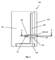
- the FIG. 1 shows a schematic representation of a key 100 for actuating a locking device of a motor vehicle.
- the key 100 comprises a housing 101 and a fixed to the housing 101 aperture 103.
- a key body 105 is inserted in the housing 101. Only a part of the key body 105 is inserted into the housing 101.
- a handle of the key body 105 is located immediately adjacent to the aperture 103 of the housing 101.
- the key 100 includes a securing device 107 to secure the key body 105 inserted into the housing 101.
- the diaphragm 103 has a first bearing 109 which supports the safety device 107.
- the first bearing 109 is formed as a shutter opening 110 and the securing device 107 is designed to be movable between a release position in which the securing device 107 releases the key body 105, and a securing position in which the securing device 107 fixes the key body 105.
- a translational movement of the securing device 107 between the release position and the securing position is effected.
- the housing side, the securing device 107 is mounted with a spring 111, wherein the spring 111 is formed so that a spring force of the spring 111, the securing device 107 repeatedly transferred to the securing position.
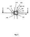
- the FIG. 2 shows a schematic representation of FIG. 1 on average AA.
- the key 100 for actuating a locking device of a motor vehicle or the securing device 107 has a latching hook 113, which can engage in a corresponding recess 115 on the key body 105.
- the housing 101 has a second bearing 117 to support the securing device 107 in addition to the first bearing 109 at the aperture 110.
- the securing device 107 has an opening 119 through which a key body 105 inserted into the housing 101 extends through the opening 119.
- the latching hook 113 of the securing device 107 is arranged on the opening 119 or on an inner side of the securing device 107 and is engaged with the recess 115 of the inserted key body 105.
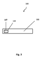
- FIG. 3 shows a schematic representation of a side view of the key 100.
- the key 100 includes the aperture 103 and in the aperture 110, the securing device 107 is mounted and arranged easily operable for a user.
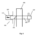
- the FIG. 4 shows a schematic representation of the securing device 107 of FIG. 2 in section BB.
- the safety device 107 in this case comprises an insertion device 121 in order to bring about an insertion of the key body 105 into the housing 101, a transfer of the securing device 107 in the release position.
- the insertion device 121 in this case has a wedge-like surface section. The inserted into the opening 119 key body 105 causes the wedge-like surface portion a force on the securing device, which is directed against the force of the spring 111. Consequently, the key body 105 can be completely inserted into the housing 101 of the key 100.
- the second bearing also on the panel, in this case, the panel itself would serve completely for the storage of the securing device.
Landscapes
- Engineering & Computer Science (AREA)
- Manufacturing & Machinery (AREA)
- Physics & Mathematics (AREA)
- General Physics & Mathematics (AREA)
- Lock And Its Accessories (AREA)
Abstract
Description
- Die vorliegende Erfindung betrifft einen Schlüssel zur Betätigung einer Schließvorrichtung eines Kraftfahrzeugs mit einem Gehäuse, einer an dem Gehäuse angeordneten Blende, einem Schlüsselkörper, welcher zumindest teilweise in das Gehäuse einführbar ausgebildet ist, und einer Sicherungsvorrichtung, um den in das Gehäuse eingeführten Schlüsselkörper zu sichern.
- Im Stand der Technik sind vielfältige Lösungen zum Befestigen von Notschlüsseln in einem Gehäuse bekannt. Meist umfassen diese Lösungen mechanische Sicherungsvorrichtungen, die innerhalb eines Schlüsselgehäuses angeordnet sind. Zusätzlich sind diese Sicherungsvorrichtungen mit einem Verriegelungsmechanismus versehen, um ein Herausfallen des Notschlüssels zu verhindern.
- Nachteilig im Stand der Technik ist, dass die bekannten Lösungen meist sehr kompliziert und kostenintensiv hergestellt werden müssen. Hierbei muss die Sicherungsvorrichtung einschließlich des Verriegelungsmechanismus zum Verhindern eines Herausfallens des Notschlüssels aus zahlreichen Bauteilen zusammengesetzt werden. Zusätzlich müssen Gleitlager und Führungen in dem Gehäuse angeordnet werden, damit eine reibungslose Funktion gewährleistet werden kann. Die funktionalen Anforderungen werden hierbei zusätzlich erhöht, weil derartige Schlüsselgehäuse häufig verklebt werden und somit eine einfache Reparatur nicht möglich ist.
- Es ist die der Erfindung zugrunde liegende Aufgabe, einen verbesserten Schlüssel zur Betätigung einer Schließvorrichtung eines Kraftfahrzeugs vorzuschlagen, welcher die Nachteile aus dem Stand der Technik überwindet.
- Diese Aufgabe wird durch den Gegenstand mit den Merkmalen nach dem unabhängigen Anspruch gelöst. Vorteilhafte Ausführungsformen der Erfindung sind Gegenstand der Figuren, der Beschreibung und der abhängigen Ansprüche.
- Erfindungsgemäß wird die Aufgabe durch einen Schlüssel zur Betätigung einer Schließvorrichtung eines Kraftfahrzeugs mit einem Gehäuse, einer an dem Gehäuse angeordneten Blende, einem Schlüsselkörper, welcher zumindest teilweise in das Gehäuse einführbar ausgebildet ist, und einer Sicherungsvorrichtung, um den in das Gehäuse eingeführten Schlüsselkörper zu sichern, gelöst, wobei die Blende ein erstes Lager aufweist, welches dazu ausgebildet ist die Sicherungsvorrichtung zu lagern. Dadurch wird beispielsweise der technische Vorteil erreicht, dass die Anzahl der Bauteile deutlich reduziert wird. Dies hat einerseits Kostenvorteile und andererseits wird der Aufwand für die Herstellung des Schlüssels stark herabgesetzt. Dadurch, dass die Blende fest mit dem Gehäuse des Schlüssels verbunden ist, kann sie gleichzeitig als Gleitlager für die Sicherungsvorrichtung dienen. Somit erfüllt die Blende einerseits die Aufgabe ein Teil des Gehäuses auszubilden und andererseits bietet sie eine einfache aber sehr zuverlässige Lagerung für die Sicherungsvorrichtung.
- Nach einer besonderen Ausführungsform ist die Sicherungsvorrichtung zwischen einer Freigabeposition, in welcher die Sicherungsvorrichtung den Schlüsselkörper freigibt, und einer Sicherungsposition, in welcher die Sicherungsvorrichtung den Schlüsselkörper fixiert, bewegbar ausgebildet. Dadurch kann durch eine einfache Betätigung der Sicherungsvorrichtung ein Entnehmen oder auch ein Einführen des Schlüsselkörpers aus dem Gehäuse bzw. in das Gehäuse erfolgen.
- Um die Bewegung zwischen Freigabeposition und Sicherungsposition der Sicherungsvorrichtung möglichst einfach zu realisieren und um besonders einfache Anforderungen an das Lager der Sicherungsvorrichtung zu stellen, erfolgt eine Bewegung der Sicherungsvorrichtung zwischen der Freigabeposition und der Sicherungsposition translatorisch.
- In einer besonders bevorzugten Ausführungsform ist die Blende mit dem Gehäuse irreversibel verbunden ausgebildet. Hierbei ist jedoch besonders bei der Montage des Schlüssels zu beachten, dass die Funktion der Blende als Lager gewährleistet bleibt.
- Insbesondere um eine translatorische Bewegung der Sicherungsvorrichtung zwischen der Freigabeposition und der Sicherungsposition und um die sich daraus ergebenden mechanischen Anforderungen besonders einfach zu realisieren, ist die Sicherungsvorrichtung stiftartig ausgebildet.
- Um die Herstellung der Blende, des Gleitlagers und der Sicherungsvorrichtung einfach und zu niedrigen Kosten zu realisieren, umfasst das erste Lager eine Blendenöffnung. Somit ist es für einen Nutzer des Schlüssels bzw. für einen Entnehmer des Schlüsselkörpers möglich, die Sicherungsvorrichtung unmittelbar zu betätigen und durch die Blendenöffnung von der Sicherungsposition in die Freigabeposition zu überführen. Dadurch wird hierbei ein einfaches Entnehmen des Schlüsselkörpers realisiert.
- Um die Sicherungsvorrichtung in einem nicht betätigten Zustand dauerhaft in der Sicherungsposition zu halten und um die Sicherungsvorrichtung nach einem manuellen Betätigen bzw. nach einem manuellen Überführen in die Freigabeposition selbstständig wieder in die Sicherungsposition zu überführen, ist die Sicherungsvorrichtung mit einer Feder gelagert. Die Feder kann hierbei als einfache Druckfeder, Biegefeder oder sonstige Feder ausgebildet sein. Hierbei ist die Feder derart ausgebildet, dass eine Federkraft der Feder die Sicherungsvorrichtung in die Sicherungsposition überführt.
- Um ein Eingreifen der Sicherungsvorrichtung in den Schlüsselkörper zu realisieren und um somit die Wirkungsweise der Sicherungsvorrichtung zu verbessern, weist die Sicherungsvorrichtung einen Rasthaken auf, der dazu ausgebildet ist, in eine Aussparung des Schlüsselkörpers einzugreifen.
- Um die Funktionsweise der Sicherungsvorrichtung zusätzlich zu verbessern und insbesondere um die translatorische Bewegung der Sicherungsvorrichtung optimal auszubilden, weist das Gehäuse ein zweites Lager auf, um die Sicherungsvorrichtung zu lagern. Das zweite Lager kann hier vorzugsweise im Inneren des Gehäuses des Schlüssels angeordnet sein. Je weiter das erste Lager und das zweite Lager voneinander entfernt angeordnet sind, desto besser ist in der Konsequenz die reibungsfreie Funktionsweise der Sicherungsvorrichtung realisierbar.
- In einer besonders bevorzugten Ausführungsform, weist die Sicherungsvorrichtung eine Öffnung auf, welche dazu ausgebildet ist, dass sich ein in das Gehäuse eingeführter Schlüsselkörper durch die Öffnung erstreckt. Somit kann ein einfaches und unmittelbares Zusammenwirken zwischen Sicherungsvorrichtung und Schlüsselkörper realisiert werden. Insbesondere in Verbindung mit einer Ausführungsform, nach welcher der Rasthaken der Sicherungsvorrichtung an der Öffnung der Sicherungsvorrichtung angeordnet ist, kann hierbei eine störungsfreie und zuverlässige Funktionsweise der Sicherungsvorrichtung realisiert werden.
- Um das Einführen des Schlüsselkörpers in das Gehäuse erheblich zu vereinfachen, umfasst die Sicherheitsvorrichtung eine Einführvorrichtung, um bei einem Einführen des Schlüsselkörpers in das Gehäuse eine Überführung der Sicherungsvorrichtung in die Freigabeposition zu bewirken. Dies kann beispielsweise dadurch realisiert werden, indem die Einführvorrichtung einen keilartigen Flächenabschnitt aufweist. Der keilartige Flächenabschnitt könnte hierbei seitlich an der Öffnung der Sicherungsvorrichtung angeordnet sein, wobei durch eine Krafteinwirkung eines in das Gehäuse einzubringenden Schlüsselkörpers auf den keilartigen Flächenabschnitt eine Kraftwirkung entsteht, die die Sicherungsvorrichtung gegen die Federkraft in die Freigabeposition überführt.
- Um die Betätigung der Sicherungsvorrichtung für einen Nutzer zusätzlich zu vereinfachen, ist die Sicherungsvorrichtung als Betätigungselement, insbesondere als Taste, ausgebildet. Hierbei ist es beispielsweise denkbar, dass die Sicherungsvorrichtung mehrteilig ausgebildet ist.
- Ausführungsbeispiele der Erfindung sind in den Zeichnungen dargestellt und werden im Folgenden näher beschrieben.
- Es zeigen:
- Fig. 1
- eine schematische Darstellung eines Schlüssels,
- Fig. 2
- eine schematische Darstellung der
Figur 1 im Schnitt A-A, - Fig. 3
- eine schematische Darstellung einer Seitenansicht des Schlüssels, und
- Fig. 4
- eine schematische Darstellung der Sicherungsvorrichtung der
Figur 2 im Schnitt B-B. - Die
Figur 1 zeigt eine schematische Darstellung eines Schlüssels 100 zur Betätigung einer Schließvorrichtung eines Kraftfahrzeugs. Der Schlüssel 100 umfasst ein Gehäuse 101 und eine an dem Gehäuse 101 fest angeordnete Blende 103. In das Gehäuse 101 ist ein Schlüsselkörper 105 eingeführt. Lediglich ein Teil des Schlüsselkörpers 105 ist in das Gehäuse 101 eingeführt. Ein Griffstück des Schlüsselkörpers 105 befindet sich unmittelbar an der Blende 103 des Gehäuses 101 angrenzend. Zusätzlich umfasst der Schlüssel 100 eine Sicherungsvorrichtung 107, um den in das Gehäuse 101 eingeführten Schlüsselkörper 105 zu sichern. Hierbei weist die Blende 103 ein erstes Lager 109 auf, welches die Sicherungsvorrichtung 107 lagert. Das erste Lager 109 ist als Blendenöffnung 110 ausgebildet und die Sicherungsvorrichtung 107 ist zwischen einer Freigabeposition, in welcher die Sicherungsvorrichtung 107 den Schlüsselkörper 105 freigibt, und einer Sicherungsposition, in welcher die Sicherungsvorrichtung 107 den Schlüsselkörper 105 fixiert, bewegbar ausgebildet. Bei einer Betätigung der stiftartig ausgebildeten Sicherungsvorrichtung 107 wird eine translatorische Bewegung der Sicherungsvorrichtung 107 zwischen der Freigabeposition und der Sicherungsposition bewirkt. Gehäuseseitig ist die Sicherungsvorrichtung 107 mit einer Feder 111 gelagert, wobei die Feder 111 so ausgebildet ist, dass eine Federkraft der Feder 111 die Sicherungsvorrichtung 107 immer wieder in die Sicherungsposition überführt. - Die
Figur 2 zeigt eine schematische Darstellung derFigur 1 im Schnitt A-A. Der Schlüssel 100 zur Betätigung einer Schließvorrichtung eines Kraftfahrzeugs bzw. die Sicherungsvorrichtung 107 weist einen Rasthaken 113 aufweist, der in eine korrespondierende Aussparung 115 an dem Schlüsselkörper 105 eingreifen kann. Zusätzlich weist das Gehäuse 101 ein zweites Lager 117 auf, um die Sicherungsvorrichtung 107 zusätzlich zu dem ersten Lager 109 an der Blendenöffnung 110 zu lagern. Die Sicherungsvorrichtung 107 weist eine Öffnung 119 auf, durch welche sich ein in das Gehäuse 101 eingeführter Schlüsselkörper 105 durch die Öffnung 119 hindurch erstreckt. Hierbei ist der Rasthaken 113 der Sicherungsvorrichtung 107 an der Öffnung 119 bzw. an einer Innenseite der Sicherungsvorrichtung 107 angeordnet und ist mit der Aussparung 115 des eingeführten Schlüsselkörpers 105 in Eingriff. - Die
Figur 3 zeigt eine schematische Darstellung einer Seitenansicht des Schlüssels 100. Der Schlüssel 100 umfasst die Blende 103 und in der Blendenöffnung 110 ist die Sicherungsvorrichtung 107 gelagert und für einen Nutzer leicht betätigbar angeordnet. - Die
Figur 4 zeigt eine schematische Darstellung der Sicherungsvorrichtung 107 derFigur 2 im Schnitt B-B. Die Sicherheitsvorrichtung 107 umfasst hierbei eine Einführvorrichtung 121, um bei einem Einführen des Schlüsselkörpers 105 in das Gehäuse 101 eine Überführung der Sicherungsvorrichtung 107 in die Freigabeposition zu bewirken. Die Einführvorrichtung 121 weist hierbei einen keilartigen Flächenabschnitt auf. Der in die Öffnung 119 eingeführte Schlüsselkörper 105 verursacht über den keilartigen Flächenabschnitt eine Kraftwirkung auf die Sicherungsvorrichtung, die gegen die Kraftwirkung der Feder 111 gerichtet ist. Folglich kann der Schlüsselkörper 105 vollständig in das Gehäuse 101 des Schlüssels 100 eingeführt werden. - Alternativ ist es möglich, die zweite Lagerstelle ebenfalls an der Blende anzuordnen, In diesem Fall würde die Blende selbst vollständig zur Lagerung der Sicherungsvorrichtung dienen.
- Die Erfindung beschränkt sich in ihrer Ausführung nicht auf die vorstehend angegebenen bevorzugten Ausführungsbeispiele. Vielmehr ist eine Anzahl von Varianten denkbar, welche von der dargestellten Lösung auch bei grundsätzlich anders gearteten Ausführungen Gebrauch macht. Sämtliche aus den Ansprüchen, der Beschreibung oder den Zeichnungen hervorgehenden Merkmale und/oder Vorteile, einschließlich konstruktive Einzelheiten, räumliche Anordnungen und Verfahrensschritte, können sowohl für sich als auch in verschiedensten Kombinationen erfindungswesentlich sein.
-
- 100
- Schlüssel
- 101
- Gehäuse
- 103
- Blende
- 105
- Schlüsselkörper
- 107
- Sicherungsvorrichtung
- 109
- Erstes Lager
- 110
- Blendenöffnung
- 111
- Feder
- 113
- Rasthaken
- 115
- Aussparung
- 117
- Zweites Lager
- 119
- Öffnung
- 121
- Einführvorrichtung
Claims (15)
- Schlüssel (100) zur Betätigung einer Schließvorrichtung eines Kraftfahrzeugs mit einem Gehäuse (101), einer an dem Gehäuse (101) angeordneten Blende (103), einem Schlüsselkörper (105), welcher zumindest teilweise in das Gehäuse (101) einführbar ausgebildet ist, und einer Sicherungsvorrichtung (107), um den in das Gehäuse (101) eingeführten Schlüsselkörper (105) zu sichern, dadurch gekennzeichnet, dass die Blende (103) ein erstes Lager (109) aufweist, welches dazu ausgebildet ist die Sicherungsvorrichtung (107) zu lagern.
- Schlüssel (100) zur Betätigung einer Schließvorrichtung eines Kraftfahrzeugs gemäß Anspruch 1, dadurch gekennzeichnet, dass die Sicherungsvorrichtung (107) zwischen einer Freigabeposition, in welcher die Sicherungsvorrichtung (107) den Schlüsselkörper (105) freigibt, und einer Sicherungsposition, in welcher die Sicherungsvorrichtung (107) den Schlüsselkörper (105) fixiert, bewegbar ausgebildet ist.
- Schlüssel (100) zur Betätigung einer Schließvorrichtung eines Kraftfahrzeugs gemäß Anspruch 1 oder 2, dadurch gekennzeichnet, dass eine Bewegung der Sicherungsvorrichtung (107) zwischen der Freigabeposition und der Sicherungsposition translatorisch erfolgt.
- Schlüssel (100) zur Betätigung einer Schließvorrichtung eines Kraftfahrzeugs gemäß einem der vorangehenden Ansprüche, dadurch gekennzeichnet, dass die Blende (103) mit dem Gehäuse (101) irreversibel verbunden ausgebildet ist.
- Schlüssel (100) zur Betätigung einer Schließvorrichtung eines Kraftfahrzeugs gemäß einem der vorangehenden Ansprüche, dadurch gekennzeichnet, dass die Sicherungsvorrichtung (107) stiftartig ausgebildet ist.
- Schlüssel (100) zur Betätigung einer Schließvorrichtung eines Kraftfahrzeugs gemäß einem der vorangehenden Ansprüche, dadurch gekennzeichnet, dass das erste Lager (109) eine Blendenöffnung (110) umfasst.
- Schlüssel (100) zur Betätigung einer Schließvorrichtung eines Kraftfahrzeugs gemäß einem der vorangehenden Ansprüche, dadurch gekennzeichnet, dass die Sicherungsvorrichtung (107) mit einer Feder (111) gelagert ist.
- Schlüssel (100) zur Betätigung einer Schließvorrichtung eines Kraftfahrzeugs gemäß Anspruch 7, dadurch gekennzeichnet, dass die Feder (111) derart ausgebildet ist, dass eine Federkraft der Feder (111) die Sicherungsvorrichtung (107) in die Sicherungsposition überführt.
- Schlüssel (100) zur Betätigung einer Schließvorrichtung eines Kraftfahrzeugs gemäß einem der vorangehenden Ansprüche, dadurch gekennzeichnet, dass die Sicherungsvorrichtung (107) einen Rasthaken (113) aufweist, der dazu ausgebildet ist, in eine Aussparung (115) des Schlüsselkörpers (105) einzugreifen.
- Schlüssel (100) zur Betätigung einer Schließvorrichtung eines Kraftfahrzeugs gemäß einem der vorangehenden Ansprüche, dadurch gekennzeichnet, dass das Gehäuse (101) ein zweites Lager (117) aufweist, um die Sicherungsvorrichtung (107) zu lagern.
- Schlüssel (100) zur Betätigung einer Schließvorrichtung eines Kraftfahrzeugs gemäß einem der vorangehenden Ansprüche, dadurch gekennzeichnet, dass die Sicherungsvorrichtung (107) eine Öffnung (119) aufweist, welche dazu ausgebildet ist, dass sich ein in das Gehäuse (101) eingeführter Schlüsselkörper (105) durch die Öffnung (119) erstreckt.
- Schlüssel (100) zur Betätigung einer Schließvorrichtung eines Kraftfahrzeugs gemäß Anspruch 11, dadurch gekennzeichnet, dass der Rasthaken (113) der Sicherungsvorrichtung (107) an der Öffnung (119) der Sicherungsvorrichtung (107) angeordnet ist.
- Schlüssel (100) zur Betätigung einer Schließvorrichtung eines Kraftfahrzeugs gemäß einem der vorangehenden Ansprüche, dadurch gekennzeichnet, dass die Sicherungsvorrichtung (107) eine Einführvorrichtung (121) umfasst, um bei einem Einführen des Schlüsselkörpers (105) in das Gehäuse (101) eine Überführung der Sicherungsvorrichtung (107) in die Freigabeposition zu bewirken.
- Schlüssel (100) zur Betätigung einer Schließvorrichtung eines Kraftfahrzeugs gemäß Anspruch 13, dadurch gekennzeichnet, dass die Einführvorrichtung (121) einen keilartigen Flächenabschnitt aufweist.
- Schlüssel (100) zur Betätigung einer Schließvorrichtung eines Kraftfahrzeugs gemäß einem der vorangehenden Ansprüche, dadurch gekennzeichnet, dass die Sicherungsvorrichtung (107) als Betätigungselement, insbesondere als Taste, ausgebildet ist.
Applications Claiming Priority (1)
| Application Number | Priority Date | Filing Date | Title |
|---|---|---|---|
| DE102015117632.7A DE102015117632A1 (de) | 2015-10-16 | 2015-10-16 | Kraftfahrzeugschlüssel |
Publications (2)
| Publication Number | Publication Date |
|---|---|
| EP3156566A1 true EP3156566A1 (de) | 2017-04-19 |
| EP3156566B1 EP3156566B1 (de) | 2020-03-04 |
Family
ID=56883594
Family Applications (1)
| Application Number | Title | Priority Date | Filing Date |
|---|---|---|---|
| EP16186918.5A Active EP3156566B1 (de) | 2015-10-16 | 2016-09-02 | Kraftfahrzeugschlüssel |
Country Status (3)
| Country | Link |
|---|---|
| EP (1) | EP3156566B1 (de) |
| CN (1) | CN107013093B (de) |
| DE (1) | DE102015117632A1 (de) |
Citations (6)
| Publication number | Priority date | Publication date | Assignee | Title |
|---|---|---|---|---|
| US20050166650A1 (en) * | 2004-01-30 | 2005-08-04 | Denso Corporation | Portable device for electronic key system |
| EP1837831A2 (de) * | 2006-03-22 | 2007-09-26 | Kabushiki Kaisha Tokai Rika Denki Seisakusho | Gehäuse für eine tragbare Vorrichtung |
| US20080229794A1 (en) * | 2007-03-21 | 2008-09-25 | Omron Corporation | Portable device |
| WO2012132461A1 (ja) * | 2011-03-31 | 2012-10-04 | パナソニック株式会社 | 電子キー |
| EP2615227A2 (de) * | 2012-01-10 | 2013-07-17 | Huf Hülsbeck & Fürst GmbH & Co. KG | Funkschlüssel für ein Kraftfahrzeug |
| EP2927394A1 (de) * | 2014-04-03 | 2015-10-07 | Huf Hülsbeck & Fürst GmbH & Co. KG | Kraftfahrzeugschlüssel mit Notschlüssel |
Family Cites Families (7)
| Publication number | Priority date | Publication date | Assignee | Title |
|---|---|---|---|---|
| JP2004353404A (ja) * | 2003-05-30 | 2004-12-16 | Denso Corp | 電子キーシステムの携帯機 |
| FR2894789B1 (fr) * | 2005-12-20 | 2008-02-22 | Valeo Securite Habitacle Sas | Dispositf de positionnement et de maintien d'une clef de secours |
| CN200985667Y (zh) * | 2006-11-15 | 2007-12-05 | 黄超逸 | 一种装卸方便的照明钥匙套 |
| CN102324332A (zh) * | 2008-07-21 | 2012-01-18 | 斯特拉泰克安全公司 | 电子通信设备和方法 |
| JP4743669B2 (ja) * | 2009-03-16 | 2011-08-10 | トヨタ自動車株式会社 | 電子キー |
| FR2981551B1 (fr) * | 2011-10-20 | 2014-04-25 | Valeo Securite Habitacle | Boitier de cle |
| JP5557829B2 (ja) * | 2011-12-07 | 2014-07-23 | オムロンオートモーティブエレクトロニクス株式会社 | 車両用携帯機 |
-
2015
- 2015-10-16 DE DE102015117632.7A patent/DE102015117632A1/de not_active Withdrawn
-
2016
- 2016-09-02 EP EP16186918.5A patent/EP3156566B1/de active Active
- 2016-10-13 CN CN201610894480.XA patent/CN107013093B/zh not_active Expired - Fee Related
Patent Citations (6)
| Publication number | Priority date | Publication date | Assignee | Title |
|---|---|---|---|---|
| US20050166650A1 (en) * | 2004-01-30 | 2005-08-04 | Denso Corporation | Portable device for electronic key system |
| EP1837831A2 (de) * | 2006-03-22 | 2007-09-26 | Kabushiki Kaisha Tokai Rika Denki Seisakusho | Gehäuse für eine tragbare Vorrichtung |
| US20080229794A1 (en) * | 2007-03-21 | 2008-09-25 | Omron Corporation | Portable device |
| WO2012132461A1 (ja) * | 2011-03-31 | 2012-10-04 | パナソニック株式会社 | 電子キー |
| EP2615227A2 (de) * | 2012-01-10 | 2013-07-17 | Huf Hülsbeck & Fürst GmbH & Co. KG | Funkschlüssel für ein Kraftfahrzeug |
| EP2927394A1 (de) * | 2014-04-03 | 2015-10-07 | Huf Hülsbeck & Fürst GmbH & Co. KG | Kraftfahrzeugschlüssel mit Notschlüssel |
Also Published As
| Publication number | Publication date |
|---|---|
| CN107013093A (zh) | 2017-08-04 |
| EP3156566B1 (de) | 2020-03-04 |
| CN107013093B (zh) | 2020-08-04 |
| DE102015117632A1 (de) | 2017-04-20 |
Similar Documents
| Publication | Publication Date | Title |
|---|---|---|
| DE102012111408B3 (de) | Verriegelungsmechanismus für Steckverbinder | |
| EP3469175A1 (de) | Türgriffmodul für ein kraftfahrzeug | |
| DE102013006826A1 (de) | Türgriffanordnung für ein Automobil | |
| DE102015118119A1 (de) | Gurtschlossführung | |
| EP2615227B1 (de) | Funkschlüssel für ein Kraftfahrzeug | |
| EP3078793A1 (de) | Türaussengriff für ein kraftfahrzeug | |
| DE102014115062A1 (de) | Türschlossmechanismus für ein Fahrzeug | |
| EP3580413B1 (de) | Kraftfahrzeugtürschloss | |
| EP2993090A1 (de) | Lenkradverriegelung | |
| DE102010034498B4 (de) | Schocksicherer Schnellverschluss für einen Endbeschlag eines Sicherheitsgurtes | |
| EP2870309A1 (de) | Schliesszylinder-schlüssel-system | |
| DE202010011805U1 (de) | Kraftfahrzeugtürverschluss | |
| EP3156566B1 (de) | Kraftfahrzeugschlüssel | |
| DE102014214870A1 (de) | Notentriegelung einer Parksperre | |
| DE102016107509A1 (de) | Kraftfahrzeugschließeinrichtung | |
| DE202014102186U1 (de) | Verschlussvorrichtung für einen Deckel eines Ablagefaches | |
| EP4062016B1 (de) | Kraftfahrzeug-schloss | |
| DE102013111467A1 (de) | Multischloss | |
| DE102013205061A1 (de) | Bedienungsmittel für eine Platte, Kombination zweier Bedienungsmittel und Verfahren zum klemmfesten Positionieren des Bedienungsmittels an einer Platte | |
| DE102016223505A1 (de) | Türgriffeinrichtung für eine Tür eines Kraftfahrzeugs, Tür, Kraftfahrzeug | |
| EP3502380A1 (de) | Türdrückerbefestigungsvorrichtung | |
| DE202010006900U1 (de) | Betätigungsvorrichtung für eine Feststellbremse | |
| DE102014115489B4 (de) | Kraftfahrzeugtürverschluss | |
| DE102014104115A1 (de) | Kraftfahrzeugschloss | |
| DE602005004098T2 (de) | Vorrichtung zum Befestigen einer Nutzlast an ein Flugzeug |
Legal Events
| Date | Code | Title | Description |
|---|---|---|---|
| PUAI | Public reference made under article 153(3) epc to a published international application that has entered the european phase |
Free format text: ORIGINAL CODE: 0009012 |
|
| STAA | Information on the status of an ep patent application or granted ep patent |
Free format text: STATUS: THE APPLICATION HAS BEEN PUBLISHED |
|
| AK | Designated contracting states |
Kind code of ref document: A1 Designated state(s): AL AT BE BG CH CY CZ DE DK EE ES FI FR GB GR HR HU IE IS IT LI LT LU LV MC MK MT NL NO PL PT RO RS SE SI SK SM TR |
|
| AX | Request for extension of the european patent |
Extension state: BA ME |
|
| STAA | Information on the status of an ep patent application or granted ep patent |
Free format text: STATUS: REQUEST FOR EXAMINATION WAS MADE |
|
| 17P | Request for examination filed |
Effective date: 20170512 |
|
| RBV | Designated contracting states (corrected) |
Designated state(s): AL AT BE BG CH CY CZ DE DK EE ES FI FR GB GR HR HU IE IS IT LI LT LU LV MC MK MT NL NO PL PT RO RS SE SI SK SM TR |
|
| GRAP | Despatch of communication of intention to grant a patent |
Free format text: ORIGINAL CODE: EPIDOSNIGR1 |
|
| STAA | Information on the status of an ep patent application or granted ep patent |
Free format text: STATUS: GRANT OF PATENT IS INTENDED |
|
| INTG | Intention to grant announced |
Effective date: 20200102 |
|
| GRAS | Grant fee paid |
Free format text: ORIGINAL CODE: EPIDOSNIGR3 |
|
| GRAA | (expected) grant |
Free format text: ORIGINAL CODE: 0009210 |
|
| STAA | Information on the status of an ep patent application or granted ep patent |
Free format text: STATUS: THE PATENT HAS BEEN GRANTED |
|
| AK | Designated contracting states |
Kind code of ref document: B1 Designated state(s): AL AT BE BG CH CY CZ DE DK EE ES FI FR GB GR HR HU IE IS IT LI LT LU LV MC MK MT NL NO PL PT RO RS SE SI SK SM TR |
|
| REG | Reference to a national code |
Ref country code: GB Ref legal event code: FG4D Free format text: NOT ENGLISH |
|
| REG | Reference to a national code |
Ref country code: CH Ref legal event code: EP |
|
| REG | Reference to a national code |
Ref country code: AT Ref legal event code: REF Ref document number: 1240527 Country of ref document: AT Kind code of ref document: T Effective date: 20200315 |
|
| REG | Reference to a national code |
Ref country code: DE Ref legal event code: R096 Ref document number: 502016009002 Country of ref document: DE |
|
| REG | Reference to a national code |
Ref country code: IE Ref legal event code: FG4D Free format text: LANGUAGE OF EP DOCUMENT: GERMAN |
|
| PG25 | Lapsed in a contracting state [announced via postgrant information from national office to epo] |
Ref country code: NO Free format text: LAPSE BECAUSE OF FAILURE TO SUBMIT A TRANSLATION OF THE DESCRIPTION OR TO PAY THE FEE WITHIN THE PRESCRIBED TIME-LIMIT Effective date: 20200604 Ref country code: FI Free format text: LAPSE BECAUSE OF FAILURE TO SUBMIT A TRANSLATION OF THE DESCRIPTION OR TO PAY THE FEE WITHIN THE PRESCRIBED TIME-LIMIT Effective date: 20200304 Ref country code: RS Free format text: LAPSE BECAUSE OF FAILURE TO SUBMIT A TRANSLATION OF THE DESCRIPTION OR TO PAY THE FEE WITHIN THE PRESCRIBED TIME-LIMIT Effective date: 20200304 |
|
| REG | Reference to a national code |
Ref country code: NL Ref legal event code: MP Effective date: 20200304 |
|
| PG25 | Lapsed in a contracting state [announced via postgrant information from national office to epo] |
Ref country code: BG Free format text: LAPSE BECAUSE OF FAILURE TO SUBMIT A TRANSLATION OF THE DESCRIPTION OR TO PAY THE FEE WITHIN THE PRESCRIBED TIME-LIMIT Effective date: 20200604 Ref country code: GR Free format text: LAPSE BECAUSE OF FAILURE TO SUBMIT A TRANSLATION OF THE DESCRIPTION OR TO PAY THE FEE WITHIN THE PRESCRIBED TIME-LIMIT Effective date: 20200605 Ref country code: HR Free format text: LAPSE BECAUSE OF FAILURE TO SUBMIT A TRANSLATION OF THE DESCRIPTION OR TO PAY THE FEE WITHIN THE PRESCRIBED TIME-LIMIT Effective date: 20200304 Ref country code: SE Free format text: LAPSE BECAUSE OF FAILURE TO SUBMIT A TRANSLATION OF THE DESCRIPTION OR TO PAY THE FEE WITHIN THE PRESCRIBED TIME-LIMIT Effective date: 20200304 Ref country code: LV Free format text: LAPSE BECAUSE OF FAILURE TO SUBMIT A TRANSLATION OF THE DESCRIPTION OR TO PAY THE FEE WITHIN THE PRESCRIBED TIME-LIMIT Effective date: 20200304 |
|
| REG | Reference to a national code |
Ref country code: LT Ref legal event code: MG4D |
|
| PG25 | Lapsed in a contracting state [announced via postgrant information from national office to epo] |
Ref country code: NL Free format text: LAPSE BECAUSE OF FAILURE TO SUBMIT A TRANSLATION OF THE DESCRIPTION OR TO PAY THE FEE WITHIN THE PRESCRIBED TIME-LIMIT Effective date: 20200304 |
|
| PG25 | Lapsed in a contracting state [announced via postgrant information from national office to epo] |
Ref country code: ES Free format text: LAPSE BECAUSE OF FAILURE TO SUBMIT A TRANSLATION OF THE DESCRIPTION OR TO PAY THE FEE WITHIN THE PRESCRIBED TIME-LIMIT Effective date: 20200304 Ref country code: PT Free format text: LAPSE BECAUSE OF FAILURE TO SUBMIT A TRANSLATION OF THE DESCRIPTION OR TO PAY THE FEE WITHIN THE PRESCRIBED TIME-LIMIT Effective date: 20200729 Ref country code: CZ Free format text: LAPSE BECAUSE OF FAILURE TO SUBMIT A TRANSLATION OF THE DESCRIPTION OR TO PAY THE FEE WITHIN THE PRESCRIBED TIME-LIMIT Effective date: 20200304 Ref country code: LT Free format text: LAPSE BECAUSE OF FAILURE TO SUBMIT A TRANSLATION OF THE DESCRIPTION OR TO PAY THE FEE WITHIN THE PRESCRIBED TIME-LIMIT Effective date: 20200304 Ref country code: EE Free format text: LAPSE BECAUSE OF FAILURE TO SUBMIT A TRANSLATION OF THE DESCRIPTION OR TO PAY THE FEE WITHIN THE PRESCRIBED TIME-LIMIT Effective date: 20200304 Ref country code: RO Free format text: LAPSE BECAUSE OF FAILURE TO SUBMIT A TRANSLATION OF THE DESCRIPTION OR TO PAY THE FEE WITHIN THE PRESCRIBED TIME-LIMIT Effective date: 20200304 Ref country code: SM Free format text: LAPSE BECAUSE OF FAILURE TO SUBMIT A TRANSLATION OF THE DESCRIPTION OR TO PAY THE FEE WITHIN THE PRESCRIBED TIME-LIMIT Effective date: 20200304 Ref country code: IS Free format text: LAPSE BECAUSE OF FAILURE TO SUBMIT A TRANSLATION OF THE DESCRIPTION OR TO PAY THE FEE WITHIN THE PRESCRIBED TIME-LIMIT Effective date: 20200704 Ref country code: SK Free format text: LAPSE BECAUSE OF FAILURE TO SUBMIT A TRANSLATION OF THE DESCRIPTION OR TO PAY THE FEE WITHIN THE PRESCRIBED TIME-LIMIT Effective date: 20200304 |
|
| REG | Reference to a national code |
Ref country code: DE Ref legal event code: R097 Ref document number: 502016009002 Country of ref document: DE |
|
| PLBE | No opposition filed within time limit |
Free format text: ORIGINAL CODE: 0009261 |
|
| STAA | Information on the status of an ep patent application or granted ep patent |
Free format text: STATUS: NO OPPOSITION FILED WITHIN TIME LIMIT |
|
| PG25 | Lapsed in a contracting state [announced via postgrant information from national office to epo] |
Ref country code: IT Free format text: LAPSE BECAUSE OF FAILURE TO SUBMIT A TRANSLATION OF THE DESCRIPTION OR TO PAY THE FEE WITHIN THE PRESCRIBED TIME-LIMIT Effective date: 20200304 Ref country code: DK Free format text: LAPSE BECAUSE OF FAILURE TO SUBMIT A TRANSLATION OF THE DESCRIPTION OR TO PAY THE FEE WITHIN THE PRESCRIBED TIME-LIMIT Effective date: 20200304 |
|
| 26N | No opposition filed |
Effective date: 20201207 |
|
| PG25 | Lapsed in a contracting state [announced via postgrant information from national office to epo] |
Ref country code: PL Free format text: LAPSE BECAUSE OF FAILURE TO SUBMIT A TRANSLATION OF THE DESCRIPTION OR TO PAY THE FEE WITHIN THE PRESCRIBED TIME-LIMIT Effective date: 20200304 Ref country code: SI Free format text: LAPSE BECAUSE OF FAILURE TO SUBMIT A TRANSLATION OF THE DESCRIPTION OR TO PAY THE FEE WITHIN THE PRESCRIBED TIME-LIMIT Effective date: 20200304 |
|
| PG25 | Lapsed in a contracting state [announced via postgrant information from national office to epo] |
Ref country code: MC Free format text: LAPSE BECAUSE OF FAILURE TO SUBMIT A TRANSLATION OF THE DESCRIPTION OR TO PAY THE FEE WITHIN THE PRESCRIBED TIME-LIMIT Effective date: 20200304 |
|
| REG | Reference to a national code |
Ref country code: CH Ref legal event code: PL |
|
| GBPC | Gb: european patent ceased through non-payment of renewal fee |
Effective date: 20200902 |
|
| REG | Reference to a national code |
Ref country code: BE Ref legal event code: MM Effective date: 20200930 |
|
| PG25 | Lapsed in a contracting state [announced via postgrant information from national office to epo] |
Ref country code: LU Free format text: LAPSE BECAUSE OF NON-PAYMENT OF DUE FEES Effective date: 20200902 |
|
| PG25 | Lapsed in a contracting state [announced via postgrant information from national office to epo] |
Ref country code: FR Free format text: LAPSE BECAUSE OF NON-PAYMENT OF DUE FEES Effective date: 20200930 |
|
| PG25 | Lapsed in a contracting state [announced via postgrant information from national office to epo] |
Ref country code: BE Free format text: LAPSE BECAUSE OF NON-PAYMENT OF DUE FEES Effective date: 20200930 Ref country code: CH Free format text: LAPSE BECAUSE OF NON-PAYMENT OF DUE FEES Effective date: 20200930 Ref country code: GB Free format text: LAPSE BECAUSE OF NON-PAYMENT OF DUE FEES Effective date: 20200902 Ref country code: LI Free format text: LAPSE BECAUSE OF NON-PAYMENT OF DUE FEES Effective date: 20200930 Ref country code: IE Free format text: LAPSE BECAUSE OF NON-PAYMENT OF DUE FEES Effective date: 20200902 |
|
| PGFP | Annual fee paid to national office [announced via postgrant information from national office to epo] |
Ref country code: DE Payment date: 20210921 Year of fee payment: 6 |
|
| PG25 | Lapsed in a contracting state [announced via postgrant information from national office to epo] |
Ref country code: TR Free format text: LAPSE BECAUSE OF FAILURE TO SUBMIT A TRANSLATION OF THE DESCRIPTION OR TO PAY THE FEE WITHIN THE PRESCRIBED TIME-LIMIT Effective date: 20200304 Ref country code: MT Free format text: LAPSE BECAUSE OF FAILURE TO SUBMIT A TRANSLATION OF THE DESCRIPTION OR TO PAY THE FEE WITHIN THE PRESCRIBED TIME-LIMIT Effective date: 20200304 Ref country code: CY Free format text: LAPSE BECAUSE OF FAILURE TO SUBMIT A TRANSLATION OF THE DESCRIPTION OR TO PAY THE FEE WITHIN THE PRESCRIBED TIME-LIMIT Effective date: 20200304 |
|
| PG25 | Lapsed in a contracting state [announced via postgrant information from national office to epo] |
Ref country code: MK Free format text: LAPSE BECAUSE OF FAILURE TO SUBMIT A TRANSLATION OF THE DESCRIPTION OR TO PAY THE FEE WITHIN THE PRESCRIBED TIME-LIMIT Effective date: 20200304 Ref country code: AL Free format text: LAPSE BECAUSE OF FAILURE TO SUBMIT A TRANSLATION OF THE DESCRIPTION OR TO PAY THE FEE WITHIN THE PRESCRIBED TIME-LIMIT Effective date: 20200304 |
|
| REG | Reference to a national code |
Ref country code: AT Ref legal event code: MM01 Ref document number: 1240527 Country of ref document: AT Kind code of ref document: T Effective date: 20210902 |
|
| PG25 | Lapsed in a contracting state [announced via postgrant information from national office to epo] |
Ref country code: AT Free format text: LAPSE BECAUSE OF NON-PAYMENT OF DUE FEES Effective date: 20210902 |
|
| REG | Reference to a national code |
Ref country code: DE Ref legal event code: R119 Ref document number: 502016009002 Country of ref document: DE |
|
| PG25 | Lapsed in a contracting state [announced via postgrant information from national office to epo] |
Ref country code: DE Free format text: LAPSE BECAUSE OF NON-PAYMENT OF DUE FEES Effective date: 20230401 |