EP3156281A1 - System zum be- und entladen - Google Patents
System zum be- und entladen Download PDFInfo
- Publication number
- EP3156281A1 EP3156281A1 EP16002144.0A EP16002144A EP3156281A1 EP 3156281 A1 EP3156281 A1 EP 3156281A1 EP 16002144 A EP16002144 A EP 16002144A EP 3156281 A1 EP3156281 A1 EP 3156281A1
- Authority
- EP
- European Patent Office
- Prior art keywords
- loading
- ambulance
- unloading
- transport vehicles
- drive control
- Prior art date
- Legal status (The legal status is an assumption and is not a legal conclusion. Google has not performed a legal analysis and makes no representation as to the accuracy of the status listed.)
- Granted
Links
- 230000007257 malfunction Effects 0.000 claims description 4
- 238000000034 method Methods 0.000 description 15
- 238000010586 diagram Methods 0.000 description 10
- 230000006870 function Effects 0.000 description 5
- 230000001419 dependent effect Effects 0.000 description 1
- 238000005516 engineering process Methods 0.000 description 1
- 238000009434 installation Methods 0.000 description 1
- 238000004519 manufacturing process Methods 0.000 description 1
Images


Classifications
-
- B—PERFORMING OPERATIONS; TRANSPORTING
- B60—VEHICLES IN GENERAL
- B60P—VEHICLES ADAPTED FOR LOAD TRANSPORTATION OR TO TRANSPORT, TO CARRY, OR TO COMPRISE SPECIAL LOADS OR OBJECTS
- B60P1/00—Vehicles predominantly for transporting loads and modified to facilitate loading, consolidating the load, or unloading
- B60P1/44—Vehicles predominantly for transporting loads and modified to facilitate loading, consolidating the load, or unloading having a loading platform thereon raising the load to the level of the load-transporting element
- B60P1/4471—General means for controlling movements of the loading platform, e.g. hydraulic systems
Definitions
- Ambulance or transport vehicles often have to be lifted large loads from the vehicles by the acting persons. Since the ambulance or cargo space is usually not ground level to the ground, the height difference between ground and cargo hold floor must be overcome during loading and unloading. For this have the Vehicles a loading and unloading device, often with a ramp on which the loads can be moved.
- the ramp is designed as a lifting platform, by means of which the distance between the plane of the ground and the plane of the cargo hold floor is overcome.
- the ramp is usually located at the rear of the cargo hold. Since the ramp in an ambulance vehicle does not close off the rear opening tightly, doors are additionally provided here. For loading and unloading, the ramp has to be folded down from the stern and the door has to be opened. Here are several orders regarding opening and closing. For a single person, this is often very complicated.
- the DE 87 10 027 U1 is a device for loading and unloading of loads at stationary or mobile charging stations, especially on a tail lift of a truck known.
- the device consists essentially of a loading platform, which is hydraulically raised, lowered and tilted.
- Tail lifts are among the loading aids for trucks, which also includes lifts and Schwenkladelifte.
- the most widespread are tail lifts, which are usually mounted on the rear of the vehicle and essentially consist of a loading platform, which is formed by means of rotatable support arms via piston-cylinder units, ie hydraulically raised, lowered and tilted.
- the DE 298 06 643 U1 relates to an installable in vehicles such as cars Auffahr Anlagen for loading or unloading a medical vehicle od.
- vehicles such as cars Auffahr kaus for loading or unloading a medical vehicle od.
- ambulances to overcome greater distances temporarily in other vehicles such. B to load cars.
- these are ramps, which are applied in pairs to the loading opening of the transport vehicle in order to enable an up or shut down of the ambulance.
- Such ramps are made of space telescopically and are brought to their full length before their use and then pushed together again.
- the known loading and unloading devices have the disadvantage that they are relatively cumbersome to operate for a single user. Here it is desirable to receive assistance in loading and unloading.
- the object of the invention is therefore to avoid the disadvantages of the prior art and to facilitate the loading and unloading of ambulance or transport vehicles for an operator.
- the loading ramp When loading and unloading various functions are performed by the operator when a vehicle is loaded or unloaded.
- the loading ramp must be extended and the doors of the cargo hold need to be opened.
- the loading ramp must be moved to a desired position so that the cargo can be pushed onto it.
- the operator has to perform numerous functions before it can even start unloading or loading.
- the present invention makes it much easier for the operator to unload or load the vehicle. By a simple operation of the drive control, the various functions of the functional devices for loading and unloading are automatically performed.
- the first functional device is designed as a door and / or gate.
- the door or gate must often be opened and closed in a particular order with respect to the other functional devices of the loading and unloading device. Therefore, it makes sense to design a functional device as a door or gate, which is controlled by the drive of the drive control.
- the second functional device is designed as a lifting platform or lift.
- This functional device must also be coordinated with or with the other functional devices such as the door or the gate. The coordination is again via the drive which is controlled by the drive control.
- the drive control coordinates the drive of the first and the second functional device according to a functional flow chart.
- the drive control coordinates in this way the various processes and sequences, as the processes have to be done for loading or unloading.
- the drive control allows operations to be performed more accurately and faster than would be possible with human power. The operations can be optimized during loading or unloading on the vehicle. Through the flowcharts, which are processed by the drive control, many unnecessary operating errors in the processes are avoided.
- a preferred embodiment of the loading and unloading device according to the invention for ambulance or transport vehicles further consists in that the actuating mechanism wirelessly actuates the drive control.
- the actuating mechanism wirelessly actuates the drive control.
- This measure makes it easier for the operator to operate the loading and unloading device.
- the wireless connection for example, radio or infrared connections are suitable.
- the actuating mechanism can thus be operated from anywhere in the reception area.
- the technology for radio links or infrared links is now inexpensive and easy to handle. While the cables have to be laid in the vehicle, this is no longer necessary for a wireless connection.
- a motor-driven push or pull device which moves a stretcher or cargo on the lifting platform or the lift.
- a sensor which detects a malfunction and / or an obstacle to the functional devices. Any technical installation may experience technical faults, for example due to material fatigue. Even obstacles can cause a malfunction of the loading and unloading. For example, an object, a person or a vehicle may be in the area of the lifting platform during extension. If the sensor did not detect such an obstacle and would abort the process via its drive control, this obstacle could be damaged.
- sensors are provided which signal the drive control the respective state of the functional devices. This measure serves to ensure that the drive control is always aware of the state of the functional devices. For example, it indicates how far a door or a gate is opened, or in which position the lifting platform is currently located.
- the sensors are preferably set so that they always signal the states to the drive control. If required, such signal states can also be stored in a memory of the drive control for later tracking.
- a further advantageous embodiment of the loading and unloading device according to the invention for ambulance or transport vehicles results from the fact that the drives for the functional devices are formed hydraulically and / or electrically. Hydraulic or electrotechnical drives can be realized particularly well in motor vehicles. In fact, these power sources are often already present in such a vehicle, so they can be shared with the functional devices in a suitable manner. This saves weight on the vehicle and keeps manufacturing costs low.
- An advantageous embodiment of the loading and unloading device according to the invention for ambulance or transport vehicles further results from the fact that the drive control activates a shutter drive of a locking mechanism for locking or unlocking the door and / or the door.
- the measure serves to automate another process during loading and unloading. This also includes the locking of the door or gate. Depending on the requirement, these must be opened or closed, whereby this process is coordinated with the other functions via the drive control. For a door must first be unlocked before it can be opened. Conversely, the door should of course first be closed before it is locked. These processes can only be coordinated via the drive control.
- the door and / or the door is designed as a loading ramp. This gives the door or gate a double function.
- a loading ramp ambulances or other loads can be moved into the transport room. If required, the loading ramp can also be used as a lifting platform at the same time.
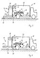
- Fig.1 schematically shows an ambulance vehicle 10 with a loading and unloading device 12 according to the invention.
- the ambulance vehicle 10 stands on a plane 13 of the road surface.
- the loading and unloading device 12 includes a first functional device 14, which is designed as a rear door 16.
- the trained as a ramp 20 secondêtsvorrlchtung 18 is in the present figure according to Fig. 1 pivoted up against a box body 22 of the ambulance vehicle 10.
- the bottom of the box body 22 lies in a plane 23, which lies above the plane 13 of the road surface.
- the 24 denotes the driver's cell of the ambulance vehicle 10.
- a cargo 26 which consists in the ambulance vehicle 10 naturally from a mobile stretcher 28.
- a drive control 32 controls the movement of the drive 30 and thus also the movement of the ramp 20.
- the drive control 32 is in turn actuated by an actuation mechanism 34 which is operated by a user.
- the actuating mechanism 34 sends its commands, such as the opening or closing of a rear opening 36, as radio signals to the drive control 32.
- the drive control 32 accordingly communicates with the actuating mechanism 34 via radio.
- the drive control 32 also controls a drive 38 for the rear door 16.
- the drive control 32 consists of a processor-controlled control unit with a memory.
- the drive controller 32 receives the respective positions and states of the functional devices 14, 18 via sensors 40. Sensors 42 detect obstacles or malfunctions of the functional devices 14, 18.
- the functional sequences for controlling the drives 30, 38 are stored. Depending on which command is sent from the actuating mechanism 34 to the drive controller 32, a specific sequence program for the opening and closing of the rear opening 36 is executed.
- Fig. 2 shows an ambulance vehicle 10 according to the Fig.1 However, with unfolded ramp 20.
- the ramp 20 is brought into a horizontal position.
- the ramp 20 is driven by the drive 30.
- the drive controller 32 controls the drive 30 for this purpose.
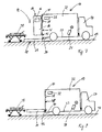
- FIG. 3 the ambulance vehicle 10 will correspond to the Figures 1 and 2 shown. In this figure, however, the rear door 16 is open. As far as correspond to the figures and identical reference numerals are used.
- the rear door 16 is actuated by the drive 38.
- the drive 38 is in turn controlled by the drive controller 32.
- the plane 13 of the first functional device 14, namely the ramp 20, is slightly below the height, as the plane 23 of the bottom of the box body 22nd
- the Fig. 4 shows the ambulance vehicle 10 as well as in the FIGS. 1, 2 and 3 is shown. As far as correspond to the figures and identical reference numerals are used. Opposite the Fig. 3 is the level 13 of the ramp 20 now on the level 23 of the box body 22. The ramp 20 was raised slightly.
- Fig. 5 shows the ambulance vehicle 10 with the loading and unloading device 12, as shown in the previous figures. As far as correspond to the figures and identical reference numerals are used.
- the stretcher 28 is pushed onto the ramp 20. This can only be reasonably realized because the plane 13 of the ramp 20 has been aligned with the plane 23 of the box body 22.
- Fig. 6 the ambulance vehicle 10 is shown according to the previous figures. As far as correspond to the figures and identical reference numerals are used.
- the ramp 20 with the stretcher 28 is now lowered to the level 13 of the pavement.
- FIG. 8 the schematic diagram of the ambulance vehicle 10 according to the previous FIGS. 1 to 7 shown.
- the ramp is slightly raised again so that it can close the rear opening 36 again.
- the rear door 16 upper drive 38 was closed.
- identical reference numerals are used in this figure.
- Fig. 9 shows analogous to the Fig.1 the ambulance vehicle 10, in which the ramp 20 of the loading and unloading device 12 is pivoted again in front of the rear opening 36.
- identical reference numerals are used here.
Landscapes
- Engineering & Computer Science (AREA)
- Transportation (AREA)
- Mechanical Engineering (AREA)
- Vehicle Step Arrangements And Article Storage (AREA)
- Loading Or Unloading Of Vehicles (AREA)
Abstract
Description
- Die Erfindung betrifft eine Be- und Entladevorrichtung für Ambulanz- oder Transportfahrzeuge, enthaltend:
- a) eine Be- und Entladeöffnung mit einer ersten Funktionsvorrichtung zum Be- und Entladen,
- b) einen Antrieb zum Betätigen der ersten Funktionsvorrichtung,
- c) eine Antriebssteuerung, welche den Antrieb ansteuert,
- d) einen Betätigungsmechanismus zum Betätigen der Antriebssteuerung.
- Bei Ambulanz- oder Transportfahrzeugen müssen von den agierenden Personen oft große lasten aus den Fahrzeugen gehoben werden. Da der Ambulanz- bzw. Frachtraum üblicherweise zum Boden nicht ebenerdig ist, muss die Höhendifferenz zwischen Boden und Frachtraumboden beim Be- bzw. Entladen überwunden werden. Hierfür haben die Fahrzeuge eine Be- und Entladevorrichtung, oft mit einer Rampe, auf der die Lasten bewegt werden können. Die Rampe ist dabei als Hubplattform ausgebildet, mit deren Hilfe der Abstand zwischen der Ebene des Bodens und der Ebene des Frachtraumbodens überwunden wird. Die Rampe ist üblicherweise am Heck des Frachtraums angeordnet. Da die Rampe bei einem Ambulanzfahrzeug die Hecköffnung nicht dicht abschließt, sind hier zusätzlich Türen vorgesehen. Zum Ein- und Ausladen ist zunächst die Rampe von dem Heck runter zu klappen und die Türe zu öffnen. Hier sind verschiedene Reihenfolgen hinsichtlich des Öffnens und Schließens einzuhalten. Für eine einzelne Person Ist dieses oft auch sehr umständlich.
- Aus der
DE 87 10 027 U1 ist eine Vorrichtung zum Be- und Entladen von Lasten an ortsfesten oder ortsveränderlichen Ladestationen, insbesondere an einer Ladebordwand eines Lastfahrzeuges , bekannt. Die Vorrichtung besteht im Wesentlichen aus einer Ladeplattform, die hydraulisch heb-, senk- und neigbar ausgebildet ist. Ladebordwände gehören zu den Ladehilfen für Lastkraftwagen, wozu auch Lifte und Schwenkladelifte gehören. Am meisten verbreitet sind die Ladebordwände, die in der Regel am Fahrzeugheck angebracht sind und im Wesentlichen aus einer Ladeplattform bestehen, die mittels drehbarer Tragarme über Kolben-Zylindereinheiten, d.h. hydraulisch heb-, senk- und neigbar ausgebildet ist. - Die
DE 298 06 643 U1 betrifft eine in Fahrzeugen wie Pkw installierbare Auffahrhilfe zum Ein- bzw. Ausladen eines Krankenfahrzeuges od. dgl. Es ist bekannt, Krankenfahrzeuge zwecks Überwindung größerer Entfernungen vorübergehend in anderweitige Fahrzeuge wie z. B, Pkw zu verladen. Hierzu und auch zum Entladen bedarf es jedoch für Kranke und Behinderte aufgrund Ihrer mangelnden Beweglichkeit und Kraftresenren und auch wegen des mitunter hohen Gewichtes derartiger Krankenfahrzeuge einer unterstützenden Einrichtung. Im einfachsten Falle sind dies Rampen, die paarweise an die Ladeöffnung des Transportfahrzeuges angelegt werden, um ein Auf- bzw. Abfahren des Krankenfahrzeuges zu ermöglichen. Derartige Rampen sind aus Platzgründen teleskopartig ausgebildet und werden vor ihrem Einsatz erst auf ihre volle Länge gebracht und danach wieder zusammengeschoben. Es sind deshalb teilweise oder vollständig mechanisierte Einrichtungen bekannt, die dem Betreiber den Kraft- und Bewegungsaufwand völlig abnehmen. Beispielsweise können dies mittels Hydraulik oder eines anderweitigen Antriebes aus einem Staubereich des Transportfahrzeuges ausfahrbare Rampen oder Bühnen sein, die dem Krankenfahrzeug das Ausfahren aus dem Transportfahrzeug entweder vollständig (Rampe) oder teilweise (Hubbühne) gestatten und umgekehrt. Derartige Einrichtungen haben Ihre Berechtigung dann, wenn der Kranke oder Behinderte überhaupt nicht in der Lage ist, mit Ausnahme der Steuerung des Vorgangs einen aktiven Beitrag zum Ver- oder Entladen des Krankenfahrzeuges zu leisten. - Die bekannten Be- und Entladevorrichtungen haben den Nachteil, dass sie für einen einzelnen Nutzer relativ umständlich zu bedienen sind. Hier ist es wünschenswert, unterstützende Hilfe bei den Be- und Entladevorgängen zu erhalten.
- Aufgabe der Erfindung ist es daher, die Nachteile des Standes der Technik zu vermeiden und den Be- bzw. Entladevorgang bei Ambulanz- oder Transportfahrzeugen für einen Bediener zu erleichtern.
- Erfindungsgemäß wird die Aufgabe dadurch gelöst, dass bei einer Be- und Entladevorrichtung für Ambulanz- oder Transportfahrzeuge der eingangs genannten Art
- e) eine zweite Funktionsvorrichtung zum Be- und Entladen vorgesehen ist, deren Antrieb von der Antriebssteuerung angesteuert wird.
- Bei Be- und Entladevorrichtungen sind vielfältige Funktionen von dem Bedienpersonal vorzunehmen, wenn ein Fahrzeug beladen oder entladen wird. Zunächst einmal muss beispielsweise die Laderampe ausgefahren werden und die Türen des Frachtraums müssen geöffnet werden. Die Laderampe muss in eine gewünschte Position bewegt werden, damit die Fracht darauf geschoben werden kann. Hier hat das Bedienpersonal zahlreiche Funktionen durchzuführen, bevor es mit dem Entladen oder Beladen überhaupt beginnen kann. Die vorliegende Erfindung erleichtert es dem Bedienpersonal erheblich das Fahrzeug zu entladen bzw. zu beladen. Durch eine einfache Betätigung der Antriebssteuerung werden die verschiedenen Funktionen der Funktionsvorrichtungen zum Be- und zum Entladen automatisch durchgeführt.
- Eine vorteilhafte Ausgestaltung der Erfindung besteht darin, dass die erste Funktionsvorrichtung als Tür und/oder Tor ausgebildet ist. Die Tür bzw. das Tor müssen oft in einer bestimmten Reihenfolge im Hinblick auf die anderen Funktionsvorrichtungen der Be- und Entladevorrichtung geöffnet und geschlossen werden. Daher ist es sinnvoll, eine Funktionsvorrichtung als Tür bzw. Tor auszugestalten, die über den Antrieb von der Antriebssteuerung gesteuert wird.
- In einer weiteren bevorzugten Ausbildung der erfindungsgemäßen Be- und Entladevorrichtung für Ambulanz- oder Transportfahrzeuge ist die zweite Funktionsvorrichtung als Hubplattform oder Lift ausgebildet. Auch diese Funktionsvorrichtung muss mit der oder mit den anderen Funktionsvorrichtungen wie der Tür bzw. dem Tor koordiniert werden. Die Koordination erfolgt wiederum über den Antrieb welcher von der Antriebssteuerung gesteuert wird.
- In einer weiteren zweckmäßigen Ausgestaltung der Erfindung koordiniert die Antriebssteuerung den Antrieb der ersten und der zweiten Funktionsvorrichtung nach einem Funktionsablaufplan. Die Antriebssteuerung koordiniert auf diese Weise die verschiedenen Abläufe und Reihenfolgen, wie die Prozesse zum Beladen oder zum Entladen zu erfolgen haben. Durch die Antriebssteuerung können die Vorgänge exakter und schneller durchgeführt werden, als es mit menschlicher Kraft möglich wäre. Die Vorgänge können beim Beladen oder Entladen an dem Fahrzeug optimiert werden. Durch die Ablaufpläne, welche von der Antriebssteuerung abgearbeitet werden, werden viele unnötige Bedienfehler bei den Prozessen vermieden.
- Eine bevorzugte Ausgestaltung der erfindungsgemäßen Be- und Entladevorrichtung für Ambulanz- oder Transportfahrzeuge besteht ferner darin, dass der Betätigungsmechanismus kabellos die Antriebssteuerung betätigt. Diese Maßnahme erleichtert dem Bedienpersonal das Betätigen der Be- und Entladevorrichtung. Für die kabellose Verbindung eignen sich beispielsweise Funk- oder Infrarotverbindungen. Der Betätigungsmechanismus kann so von jedem beliebigen Ort im Empfangsbereich bedient werden. Die Technik für Funkverbindungen oder Infrarotverbindungen ist mittlerweile kostengünstig und leicht zu verarbeiten. Während die Kabel im Fahrzeug verlegt werden müssen, ist dieses bei einer kabellosen Verbindung nun nicht mehr erforderlich.
- In einer weiteren zweckmäßigen Ausgestaltung der Erfindung ist eine von einem Motor angetriebene Schub- oder Zugvorrichtung vorgesehen, welche eine Krankenbahre oder Transportgut auf die Hubplattform bzw. den Lift bewegt.
- Es hat sich als eine vorteilhafte Ausgestaltung der Erfindung erwiesen, wenn für die Be- und Entladevorrichtung von Ambulanz- oder Transportfahrzeugen der Motor für die Schub- oder Zugvorrichtung von der Antriebssteuerung betätigt wird. Hierdurch werden einige Steuerschritte eingespart, weil nicht jeder einzelne Motor eine eigene Antriebssteuerung benötigt. Zudem können die Antriebe bzw. Motoren in Ihrem Ablauf miteinander koordiniert werden.
- Vorzugsweise ist bei der erfindungsgemäßen Be- und Entladevorrichtung für Ambulanz- oder Transportfahrzeuge ein Sensor vorgesehen ist, welcher eine Fehlfunktion und/oder ein Hindernis für die Funktionsvorrichtungen erkennt. Bei jeder technischen Anlage können technische Fehler, beispielsweise durch Materialermüdung, auftreten. Auch Hindernisse können eine Fehlfunktion der Be- und Entladevorrichtung verursachen. Beispielsweise kann ein Gegenstand, eine Person oder Fahrzeug im Bereich der Hubplattform beim Ausfahren stehen. Wenn der Sensor ein solches Hindernis nicht erkennen würde und den Vorgang über seine Antriebssteuerung abbrechen würde, könnte dieses Hindernis zu Schaden kommen.
- In einer weiteren vorteilhaften Ausbildung der erfindungsgemäßen Be- und Entladevorrichtung sind Sensoren vorgesehen, welche der Antriebssteuerung den jeweiligen Zustand der Funktionsvorrichtungen signalisieren. Diese Maßnahme dient dazu, dass der Antriebssteuerung jederzeit bekannt ist, in welchem Zustand die Funktionsvorrichtungen sind. Beispielsweise wird signalisiert, wie weit eine Tür bzw. ein Tor geöffnet sind, oder in welcher Position sich die Hubplattform gerade befindet. Die Sensoren sind vorzugsweise so eingestellt, dass sie die Zustände immer aktuell an die Antriebssteuerung signalisieren. Bei Bedarf können solche Signalzustände auch in einem Speicher der Antriebssteuerung zur späteren Nachverfolgung gespeichert werden.
- Eine weitere vorteilhafte Ausgestaltung der erfindungsgemäßen Be- und Entladevorrichtung für Ambulanz- oder Transportfahrzeuge ergibt sich dadurch, dass die Antriebe für die Funktionsvorrichtungen hydraulisch und/oder elektrisch ausgebildet sind. Hydraulische oder elektrotechnische Antriebe lassen sich in Kraftfahrzeugen besonders gut realisieren. Diese Antriebsquellen sind nämlich oft bereits in einem solchen Fahrzeug vorhanden, Sie lassen sich daher in geeigneter Weise mit den Funktionsvorrichtungen gemeinsam verwenden. Dies spart Gewicht am Fahrzeug und hält die Herstellungskosten gering.
- Eine vorteilhafte Ausgestaltung der erfindungsgemäßen Be- und Entladevorrichtung für Ambulanz- oder Transportfahrzeuge ergibt sich weiterhin dadurch, dass die Antriebssteuerung einen Verschlussantrieb eines Verriegelungsmechanismus zum Verriegeln oder zum Entriegeln der Tür und/oder des Tors ansteuert. Die Maßnahme dient dazu, einen weiteren Prozess beim Be- und Entladen zu automatisieren. Dazu gehört auch die Verriegelung der Tür bzw. des Tors. Je nach Anforderung müssen diese geöffnet oder geschlossen werden, wobei dieser Prozess mit den anderen Funktionen über die Antriebssteuerung koordiniert wird. Denn eine Tür muss zuerst entriegelt werden, bevor sie geöffnet werden darf. Umgekehrt sollte die Tür natürlich erst verschlossen werden, bevor sie verriegelt wird. Diese Abläufe können nur Ober die Antriebssteuerung koordiniert werden.
- In einer weiteren bevorzugten Ausbildung der erfindungsgemäßen Be- und Entladevorrichtung für Ambulanz- oder Transportfahrzeuge ist die Tür und/oder das Tor als Laderampe ausgebildet. Hierdurch erhalten die Tür bzw. das Tor eine doppelte Funktion. Als Laderampe können Krankenbahren oder andere Lasten in den Transportraum bewegt werden. Bel Bedarf kann die Laderampe auch gleichzeitig als Hubplattform verwendet werden.
- Weitere Ausgestaltungen und Vorteile ergeben sich aus dem Gegenstand der Unteransprüche, sowie den Zeichnungen mit den dazugehörigen Beschreibungen, Ein Ausführungsbeispiel ist nachstehend unter Bezugnahme auf die beigefügten Zeichnungen näher erläutert. Die Erfindung soll nicht alleine auf diese aufgeführten Ausführungsbeispiele beschränkt werden. Sie dienen lediglich zur näheren Erläuterung der Erfindung. Die Erfindung soll sich auf alle Gegenstände beziehen, die jetzt und zukünftig der Fachmann als naheliegend zur Realisierung der Erfindung heranziehen würde.
-
- Fig. 1
- zeigt in einer schematischen Prinzipskizze ein Ambulanzfahrzeug mit einer erfindungsgemäßen Be- und Entladevorrichtung, bei der die Rampe hochgeschwenkt ist.
- Fig. 2
- zeigt in einer schematischen Prinzipskizze gemäß
Fig. 1 ein Ambulanzfahrzeug, bei der die Rampe in eine horizontale Position ausgefahren ist. - Fig. 3
- zeigt in einer schematischen Prinzipskizze gemäß den
Figuren 1 und 2 ein Ambulanzfahrzeug, bei dem die Hecktüre geöffnet ist. - Fig. 4
- zeigt in einer schematischen Prinzipskizze gemäß den
Figuren 1, 2 und3 ein Ambulanzfahrzeug, bei dem die Rampe auf die Ebene des Frachtraums angehoben ist. - Fig. 5
- zeigt in einer schematischen Prinzipskizze gemäß den vorherigen Figuren ein Ambulanzfahrzeug mit einer erfindungsgemäßen Be- und Entladevorrichtung, bei der die Krankenbahre auf die Rampe geschoben ist.
- Fig. 6
- zeigt in einer schematischen Prinzipskizze gemäß den vorherigen Figuren ein Ambulanzfahrzeug, bei der die Rampe mit der Krankenbahre auf den Boden abgesenkt ist.
- Fig. 7
- zeigt in einer schematischen Prinzipskizze gemäß den
Figuren 1 bis 6 ein Ambulanzfahrzeug, bei dem die Krankenbahre von der Rampe auf den Boden geschoben wurde. - Fig. 8
- zeigt in einer schematischen Prinzipskizze gemäß den vorherigen
Figuren 1 bis 7 ein Ambulanzfahrzeug, bei dem die Rampe wieder angehoben ist. - Fig. 9
- zeigt in einer schematischen Prinzipskizze gemäß den
Figuren 1, 2 und3 ein Ambulanzfahrzeug, bei dem die Rampe der erfindungsgemäßen Be- und Entladevorrichtung wieder geschwenkt ist. -
Fig.1 zeigt schematisch ein Ambulanzfahrzeug 10 mit einer erfindungsgemäßen Be- und Entladevorrichtung 12. Das Ambulanzfahrzeug 10 steht auf einer Ebene 13 des Straßenbodens. Die Be- und Entladevorrichtung 12 enthält eine erste Funktionsvorrichtung 14, welche als Hecktüre 16 ausgebildet ist. Weiterhin umfasst die Be- und Entladevorrichtung 12 eine zweite Funktionsvorrichtung 18, welche als Rampe 20 ausgebildet ist. Die als Rampe 20 ausgebildete zweite Funktionsvorrlchtung 18 ist in vorliegender Abbildung gemäßFig. 1 gegen einen Kofferaufbau 22 des Ambulanzfahrzeugs 10 hochgeschwenkt. Der Boden des Kofferaufbaus 22 liegt in einer Ebene 23, welche über der Ebene 13 des Straßenbodens liegt. - Mit 24 wird die Fahrerzelle des Ambulanzfahrzeugs 10 bezeichnet. In dem Kofferaufbau 22 befindet sich symbolisch eine Fracht 26, welche In dem Ambulanzfahrzeug 10 naturgemäß aus einer fahrbaren Krankenbahre 28 besteht.
- Mit einem Antrieb 30, welcher aus einem Elektromotor besteht, wird die Rampe 20 angetrieben. Eine Antriebssteuerung 32 steuert die Bewegung des Antriebs 30 und somit auch die Bewegung der Rampe 20. Die Antriebssteuerung 32 wird wiederum von einem Betätigungsmechanismus 34 betätigt, welche von einem Nutzer bedient wird. Der Betätigungsmechanismus 34 sendet hierfür seine Befehle, wie das Öffnen oder das Schließen einer Hecköffnung 36, als Funksignale an die Antriebssteuerung 32. Die Antriebssteuerung 32 kommuniziert entsprechend mit dem Betätigungsmechanismus 34 über Funk.
- Die Antriebssteuerung 32 steuert ferner auch einen Antrieb 38 für die Hecktüre 16. Die Antriebssteuerung 32 besteht aus einer prozessorgesteuerten Steuereinheit mit einem Speicher. Die Antriebssteuerung 32 erhält die jeweiligen Positionen und Zustände der Funktionsvorrichtungen 14, 18 über Sensoren 40. Sensoren 42 erfassen Hindernisse oder Fehlfunktionen der Funktionsvorrichtungen 14, 18. In der Antriebssteuerung 32 sind die Funktionsabläufe zur Steuerung der Antriebe 30, 38 gespeichert. Je nachdem, welcher Befehl von dem Betätigungsmechanismus 34 an die Antriebssteuerung 32 gesendet wird, wird ein bestimmtes Ablaufprogramm für das öffnen bzw. Schließen der Hecköffnung 36 abgearbeitet.
-
Fig. 2 zeigt ein Ambulanzfahrzeug 10 entsprechend derFig.1 jedoch mit ausgeklappter Rampe 20. Soweit sich die Figuren entsprechen werden auch identische Bezugszeichen verwendet. Sobald der Betätigungsmechanismus 34 zum Öffnen betätigt wurde, wird in einem ersten Schritt die Rampe 20 in eine horizontale Position gebracht. Für diesen Prozess wird die Rampe 20 dabei von dem Antrieb 30 angetrieben. Die Antriebssteuerung 32 steuert dazu den Antrieb 30. - In
Fig. 3 wird das Ambulanzfahrzeug 10 entsprechend denFiguren 1 und 2 dargestellt. In dieser Abbildung ist jedoch die die Hecktüre 16 geöffnet. Soweit sich die Figuren entsprechen werden auch identische Bezugszeichen verwendet. Die Hecktüre 16 wird von dem Antrieb 38 betätigt. Der Antrieb 38 wird wiederum von der Antriebssteuerung 32 gesteuert. Die Ebene 13 der ersten Funktionsvorrichtung 14, nämlich der Rampe 20, befindet sich leicht unterhalb der Höhe, wie die Ebene 23 des Bodens des Kofferaufbaus 22. - Die
Fig. 4 zeigt das Ambulanzfahrzeug 10 wie es auch in denFiguren 1, 2 und3 dargestellt ist. Soweit sich die Figuren entsprechen werden auch identische Bezugszeichen verwendet. Gegenüber derFig. 3 befindet sich die Ebene 13 der Rampe 20 nun auf der Ebene 23 des Kofferaufbaus 22. Die Rampe 20 wurde dazu geringfügig angehoben. -
Fig. 5 zeigt das Ambulanzfahrzeug 10 mit der Be- und Entladevorrichtung 12, wie es auch in den vorherigen Figuren dargestellt wird. Soweit sich die Figuren entsprechen werden auch identische Bezugszeichen verwendet. In dieser Abbildung vonFig. 5 ist die Krankenbahre 28 auf die Rampe 20 geschoben. Dies lässt sich nur vernünftig realisieren, weil die Ebene 13 der Rampe 20 an die Ebene 23 des Kofferaufbaus 22 angeglichen wurde. - In
Fig. 6 wird das Ambulanzfahrzeug 10 entsprechend den vorherigen Figuren dargestellt. Soweit sich die Figuren entsprechen werden auch identische Bezugszeichen verwendet. Hier ist ein weiterer Schritt bei der Entladung der Krankenbahre 28 vorgenommen worden. Die Rampe 20 mit der Krankenbahre 28 ist nun auf die Ebene 13 des Straßenbodens abgesenkt. - Da die Rampe 20 nun das Niveau des Straßenboden erreicht hat, kann, wie in
Fig. 7 gezeigt, die Krankenbahre 28 von der Rampe 20 heruntergeschoben werden. DieFig. 7 entspricht weitestgehend den vorherigen Figuren. Die Bezugszeichen werden daher entsprechend verwendet. - In
Fig. 8 wird die Prinzipskizze des Ambulanzfahrzeugs 10 gemäß den vorherigenFiguren 1 bis 7 dargestellt. In dieser Fig. ist die Rampe allerdings wieder leicht angehoben, damit sie wieder die Hecköffnung 36 schließen kann. Zuvor wurde jedoch die Hecktüre 16 Ober den Antrieb 38 geschlossen. Soweit sich die Figuren mit den vorherigen Figuren entsprechen werden auch bei dieser Abbildung identische Bezugszeichen verwendet. -
Fig. 9 zeigt analog zu derFig.1 das Ambulanzfahrzeug 10, bei dem die Rampe 20 der Be- und Entladevorrichtung 12 wieder vor die Hecköffnung 36 geschwenkt ist. Soweit sich die Figuren entsprechen werden auch hier identische Bezugszeichen verwendet. - Ein Nutzer initliert über den Betätigungsmechanismus 34 den Prozess zum Öffnen oder zum Schließen der Be- und Entladevorrichtung 12. Der Betätigungsmechanismus 34 signalisiert der Antriebssteuerung 32 einen Prozess zu starten. Die Antriebssteuerung 32 arbeitet je nach Bedarf ein Funktionsablaufplan zum Öffnen oder zum Schließen ab. Hier ist vor allem die Reihenfolge festgelegt, welche bei den einzelnen Prozessen unterschiedlich ist. Die Steuerung der einzelnen Vorgänge erfolgt dabei durch Ansteuerung der Antriebe 30, 38, welche die Funktionsvorrichtungen 14 bzw. 18 betätigen. Die Sensoren 40 und 42 überwachen dabei die Prozesse. Bei Fehlern oder Hindernissen werden die Prozesse unmittelbar abgebrochen.
- 10
- Ambulanzfahrzeug
- 12
- Be- und Entladevorrichtung
- 13
- Ebene des Straßenbodens
- 14
- Erste Funktionsvorrichtung
- 16
- Hecktüre
- 18
- Zweite Funktionsvorrichtung
- 20
- Rampe
- 22
- Kofferaufbau
- 23
- Ebene des Bodens des Kofferaufbaus
- 24
- Fahrerzelle
- 26
- Fracht
- 28
- Krankenbahre
- 30
- Antrieb für die Rampe
- 32
- Antriebssteuerung
- 34
- Betätigungsmechanismus
- 36
- Hecköffnung
- 38
- Antrieb für die Hecktüre
- 40
- Sensoren
- 42
- Sensoren
Claims (12)
- Be- und Entladevorrichtung (12) für Ambulanz- oder Transportfahrzeuge (10) enthaltend:a) eine Be- und Entladeöffnung (36) mit einer ersten Funktionsvorrichtung (14) zum Be- und Entladen,b) einen Antrieb (38) zum Betätigen der ersten Funktionsvorrichtung (14),c) eine Antriebssteuerung (32), welche den Antrieb (38) ansteuert,d) einen Betätigungsmechanismus (34) zum Betätigen der Antriebssteuerung (32),dadurch gekennzeichnet, dasse) eine zweite Funktionsvorrichtung (18) zum Be- und Entladen vorgesehen ist, deren Antrieb (30) von der Antriebssteuerung (32) angesteuert wird.
- Be- und Entladevorrichtung (12) für Ambulanz- oder Transportfahrzeuge (10) nach Anspruch 1, dadurch gekennzeichnet, dass die erste Funktionsvorrichtung (14) als Tür (16) und/oder Tor ausgebildet ist.
- Be- und Entladevorrichtung (12) für Ambulanz- oder Transportfahrzeuge (10) nach einem der Ansprüche 1 oder 2, dadurch gekennzeichnet, dass die zweite Funktionsvorrichtung (18) als Hubplattform (20) oder Lift ausgebildet ist.
- Be- und Entladevorrichtung (12) für Ambulanz- oder Transportfahrzeuge (10) nach einem der Ansprüche 1 bis 3, dadurch gekennzeichnet, dass die Antriebssteuerung (32) den Antrieb (30, 38) der ersten und der zweiten Funktionsvorrichtung (14, 8) nach einem Funktionsablaufplan koordiniert.
- Be- und Entladevorrichtung (12) für Ambulanz- oder Transportfahrzeuge (10) nach einem der Ansprüche 1 bis 4, dadurch gekennzeichnet, dass der Betätigungsmechanismus (34) kabellos die Antriebssteuerung (32) betätigt.
- Be- und Entladevorrichtung (12) für Ambulanz- oder Transportfahrzeuge (10) nach einem der Ansprüche 1 bis 5, dadurch gekennzeichnet, dass eine von einem Motor angetriebene Schub- oder Zugvorrichtung eine Krankenbahre (28) oder Transportgut auf die Hubplattform (20) bzw. den Lift bewegt.
- Be- und Entladevorrichtung (12) für Ambulanz- oder Transportfahrzeuge (10) nach Anspruch 6, dadurch gekennzeichnet, dass der Motor für die Schub- oder Zugvorrichtung von der Antriebssteuerung (32) betätigt wird.
- Be- und Entladevorrichtung (12) für Ambulanz- oder Transportfahrzeuge (10) nach einem der Ansprüche 1 bis 7, dadurch gekennzeichnet, dass ein Sensor (42) vorgesehen ist, welcher eine Fehlfunktion und/oder ein Hindernis für die Funktionsvorrichtungen (14, 18) erkennt.
- Be- und Entladevorrichtung (12) für Ambulanz- oder Transportfahrzeuge (10) nach einem der Ansprüche 1 bis 8, dadurch gekennzeichnet, dass Sensoren (40) vorgesehen sind, welche der Antriebssteuerung (32) den jeweiligen Zustand der Funktionsvorrichtungen (14, 8) signalisieren.
- Be- und Entladevorrichtung (12) für Ambulanz- oder Transportfahrzeuge (10) nach einem der Ansprüche 1 bis 9, dadurch gekennzeichnet, dass die Antriebe (30, 38) für die Funktionsvorrichtungen (14, 18) hydraulisch und/oder elektrisch ausgebildet sind.
- Be- und Entladevorrichtung (12) für Ambulanz- oder Transportfahrzeuge (10) nach einem der Ansprüche 2 bis 10, dadurch gekennzeichnet, dass die Antriebssteuerung (32) einen Verschlussantrieb eines Verriegelungsmechanismus zum Verriegeln oder zum Entriegeln der Tür (16) und/oder des Tors ansteuert.
- Be- und Entladevorrichtung (12) für Ambulanz- oder Transportfahrzeuge (10) nach einem der Ansprüche 2 bis 11, dadurch gekennzeichnet, dass die Tür (16) und/oder das Tor als Laderampe ausgebildet sind.
Applications Claiming Priority (1)
| Application Number | Priority Date | Filing Date | Title |
|---|---|---|---|
| DE102015117432.4A DE102015117432A1 (de) | 2015-10-13 | 2015-10-13 | System zum Be- und Entladen |
Publications (2)
| Publication Number | Publication Date |
|---|---|
| EP3156281A1 true EP3156281A1 (de) | 2017-04-19 |
| EP3156281B1 EP3156281B1 (de) | 2019-12-04 |
Family
ID=57120982
Family Applications (1)
| Application Number | Title | Priority Date | Filing Date |
|---|---|---|---|
| EP16002144.0A Active EP3156281B1 (de) | 2015-10-13 | 2016-10-05 | System zum be- und entladen |
Country Status (2)
| Country | Link |
|---|---|
| EP (1) | EP3156281B1 (de) |
| DE (1) | DE102015117432A1 (de) |
Citations (6)
| Publication number | Priority date | Publication date | Assignee | Title |
|---|---|---|---|---|
| DE8710027U1 (de) | 1987-07-22 | 1987-09-10 | Verhulst, Arthur, 5014 Kerpen | Vorrichtung zum Be- und Entladen von Lasten an ortsfesten oder ortsveränderlichen Ladestationen |
| DE29806643U1 (de) | 1998-04-11 | 1998-09-03 | FIBER-TECH Umwelttechnik GmbH, 09117 Chemnitz | Auffahrhilfe für Fahrzeuge |
| US20030044266A1 (en) * | 2001-08-31 | 2003-03-06 | Sieto Vandillen | Power rear door interface for a vehicle having a rear entry folding ramp |
| US6825628B2 (en) * | 2000-09-01 | 2004-11-30 | The Braun Corporation | Electronic controller for vehicular wheelchair access |
| EP1918157A1 (de) * | 2006-10-30 | 2008-05-07 | Jörg Stauffer | Vorrichtung zum Heben und Transferieren von Gütern sowie Handhubwagen |
| DE102014100056A1 (de) * | 2013-11-18 | 2015-05-21 | Tente Gmbh & Co. Kg | Steuerung von an einem Verfahrteil angebrachten Rollen |
-
2015
- 2015-10-13 DE DE102015117432.4A patent/DE102015117432A1/de not_active Withdrawn
-
2016
- 2016-10-05 EP EP16002144.0A patent/EP3156281B1/de active Active
Patent Citations (6)
| Publication number | Priority date | Publication date | Assignee | Title |
|---|---|---|---|---|
| DE8710027U1 (de) | 1987-07-22 | 1987-09-10 | Verhulst, Arthur, 5014 Kerpen | Vorrichtung zum Be- und Entladen von Lasten an ortsfesten oder ortsveränderlichen Ladestationen |
| DE29806643U1 (de) | 1998-04-11 | 1998-09-03 | FIBER-TECH Umwelttechnik GmbH, 09117 Chemnitz | Auffahrhilfe für Fahrzeuge |
| US6825628B2 (en) * | 2000-09-01 | 2004-11-30 | The Braun Corporation | Electronic controller for vehicular wheelchair access |
| US20030044266A1 (en) * | 2001-08-31 | 2003-03-06 | Sieto Vandillen | Power rear door interface for a vehicle having a rear entry folding ramp |
| EP1918157A1 (de) * | 2006-10-30 | 2008-05-07 | Jörg Stauffer | Vorrichtung zum Heben und Transferieren von Gütern sowie Handhubwagen |
| DE102014100056A1 (de) * | 2013-11-18 | 2015-05-21 | Tente Gmbh & Co. Kg | Steuerung von an einem Verfahrteil angebrachten Rollen |
Also Published As
| Publication number | Publication date |
|---|---|
| EP3156281B1 (de) | 2019-12-04 |
| DE102015117432A1 (de) | 2017-04-13 |
Similar Documents
| Publication | Publication Date | Title |
|---|---|---|
| DE102007046868A1 (de) | Transportvorrichtung für Ladungsträger und Verfahren zu deren Steuerung | |
| DE102021117395A1 (de) | Kraftbetätigungseinheit für angetriebene tür mit einer mechanisch betätigten kupplungs-/bremseinheit | |
| EP3020381B1 (de) | Hilfsvorrichtung für eine fahrtrage | |
| DE102017220200B3 (de) | Ladesystem | |
| DE102014000887A1 (de) | Verfahren zum Be- und Entladen eines fahrbaren Transportwagens und fahrbarer Transportwagen, insbesondere fahrbarer Routenzug-Transportwagen | |
| CH702380A2 (de) | Anhängerzug. | |
| DE60011738T2 (de) | Wagen zum Befördern von Fahrzeugen in einem Parkhaus | |
| EP2593333A1 (de) | Fahrzeug in modularer bauweise | |
| WO2010031384A2 (de) | Verfahren zum starten einer drohne | |
| EP3611119B1 (de) | Vorschub-ladebrücke sowie verfahren zum betrieb derselben | |
| DE60318088T2 (de) | Koffervorrichtung für ein auto | |
| DE202019106629U1 (de) | Wagenheber | |
| EP3156281B1 (de) | System zum be- und entladen | |
| DE10347564B4 (de) | Verkehrsmittel für Wechselbrücke | |
| DE202013105333U1 (de) | Transporthubwagen zum Transport einer Last | |
| DE102017220199B3 (de) | Ladevorrichtung, Kraftfahrzeug und Mobilitätssystem | |
| EP3170696B1 (de) | Behälteraufsteller-vorrichtung, insbesondere siloaufsteller-vorrichtung, für ein nutzfahrzeug sowie nutzfahrzeug mit derartiger behälteraufsteller-vorrichtung | |
| DE102011103382B4 (de) | Verladesystem, Transportsystem und Verfahren zum Transportieren eines Rollstuhls | |
| DE19637907C2 (de) | Elektrohydraulische Dachliftanlage | |
| DE102017220197A1 (de) | Hebevorrichtung für einen Rollstuhl und Kraftfahrzeug | |
| DE102017220196A1 (de) | Ladevorrichtung, Kraftfahrzeug und Mobilitätssystem | |
| EP1118500A1 (de) | Ladebordwandsystem | |
| DE102019211889B4 (de) | Verfahren zum Heben und/oder Absenken einer Last, Hebeplattform, Parkroboter und System | |
| DE69809858T2 (de) | Einheit aus abnehmbarer Karosseriebaugruppe und Trägerfahrzeug, Methode zum Kuppeln einer derartigen Einheit, sowie mit einer solchen Einheit ausgerüstetes Fahrzeug | |
| DE102017220198B3 (de) | Ladesystem, Kraftfahrzeug und Verfahren zum Verladen eines Elektrorollstuhls |
Legal Events
| Date | Code | Title | Description |
|---|---|---|---|
| PUAI | Public reference made under article 153(3) epc to a published international application that has entered the european phase |
Free format text: ORIGINAL CODE: 0009012 |
|
| STAA | Information on the status of an ep patent application or granted ep patent |
Free format text: STATUS: THE APPLICATION HAS BEEN PUBLISHED |
|
| AK | Designated contracting states |
Kind code of ref document: A1 Designated state(s): AL AT BE BG CH CY CZ DE DK EE ES FI FR GB GR HR HU IE IS IT LI LT LU LV MC MK MT NL NO PL PT RO RS SE SI SK SM TR |
|
| AX | Request for extension of the european patent |
Extension state: BA ME |
|
| STAA | Information on the status of an ep patent application or granted ep patent |
Free format text: STATUS: REQUEST FOR EXAMINATION WAS MADE |
|
| 17P | Request for examination filed |
Effective date: 20171016 |
|
| RBV | Designated contracting states (corrected) |
Designated state(s): AL AT BE BG CH CY CZ DE DK EE ES FI FR GB GR HR HU IE IS IT LI LT LU LV MC MK MT NL NO PL PT RO RS SE SI SK SM TR |
|
| GRAP | Despatch of communication of intention to grant a patent |
Free format text: ORIGINAL CODE: EPIDOSNIGR1 |
|
| STAA | Information on the status of an ep patent application or granted ep patent |
Free format text: STATUS: GRANT OF PATENT IS INTENDED |
|
| INTG | Intention to grant announced |
Effective date: 20190606 |
|
| GRAS | Grant fee paid |
Free format text: ORIGINAL CODE: EPIDOSNIGR3 |
|
| GRAA | (expected) grant |
Free format text: ORIGINAL CODE: 0009210 |
|
| STAA | Information on the status of an ep patent application or granted ep patent |
Free format text: STATUS: THE PATENT HAS BEEN GRANTED |
|
| AK | Designated contracting states |
Kind code of ref document: B1 Designated state(s): AL AT BE BG CH CY CZ DE DK EE ES FI FR GB GR HR HU IE IS IT LI LT LU LV MC MK MT NL NO PL PT RO RS SE SI SK SM TR |
|
| REG | Reference to a national code |
Ref country code: GB Ref legal event code: FG4D Free format text: NOT ENGLISH |
|
| REG | Reference to a national code |
Ref country code: CH Ref legal event code: EP |
|
| REG | Reference to a national code |
Ref country code: AT Ref legal event code: REF Ref document number: 1208987 Country of ref document: AT Kind code of ref document: T Effective date: 20191215 |
|
| REG | Reference to a national code |
Ref country code: DE Ref legal event code: R096 Ref document number: 502016007818 Country of ref document: DE |
|
| REG | Reference to a national code |
Ref country code: IE Ref legal event code: FG4D Free format text: LANGUAGE OF EP DOCUMENT: GERMAN |
|
| REG | Reference to a national code |
Ref country code: NL Ref legal event code: MP Effective date: 20191204 |
|
| REG | Reference to a national code |
Ref country code: LT Ref legal event code: MG4D |
|
| PG25 | Lapsed in a contracting state [announced via postgrant information from national office to epo] |
Ref country code: GR Free format text: LAPSE BECAUSE OF FAILURE TO SUBMIT A TRANSLATION OF THE DESCRIPTION OR TO PAY THE FEE WITHIN THE PRESCRIBED TIME-LIMIT Effective date: 20200305 Ref country code: NO Free format text: LAPSE BECAUSE OF FAILURE TO SUBMIT A TRANSLATION OF THE DESCRIPTION OR TO PAY THE FEE WITHIN THE PRESCRIBED TIME-LIMIT Effective date: 20200304 Ref country code: FI Free format text: LAPSE BECAUSE OF FAILURE TO SUBMIT A TRANSLATION OF THE DESCRIPTION OR TO PAY THE FEE WITHIN THE PRESCRIBED TIME-LIMIT Effective date: 20191204 Ref country code: BG Free format text: LAPSE BECAUSE OF FAILURE TO SUBMIT A TRANSLATION OF THE DESCRIPTION OR TO PAY THE FEE WITHIN THE PRESCRIBED TIME-LIMIT Effective date: 20200304 Ref country code: LT Free format text: LAPSE BECAUSE OF FAILURE TO SUBMIT A TRANSLATION OF THE DESCRIPTION OR TO PAY THE FEE WITHIN THE PRESCRIBED TIME-LIMIT Effective date: 20191204 Ref country code: SE Free format text: LAPSE BECAUSE OF FAILURE TO SUBMIT A TRANSLATION OF THE DESCRIPTION OR TO PAY THE FEE WITHIN THE PRESCRIBED TIME-LIMIT Effective date: 20191204 Ref country code: LV Free format text: LAPSE BECAUSE OF FAILURE TO SUBMIT A TRANSLATION OF THE DESCRIPTION OR TO PAY THE FEE WITHIN THE PRESCRIBED TIME-LIMIT Effective date: 20191204 |
|
| PG25 | Lapsed in a contracting state [announced via postgrant information from national office to epo] |
Ref country code: HR Free format text: LAPSE BECAUSE OF FAILURE TO SUBMIT A TRANSLATION OF THE DESCRIPTION OR TO PAY THE FEE WITHIN THE PRESCRIBED TIME-LIMIT Effective date: 20191204 Ref country code: RS Free format text: LAPSE BECAUSE OF FAILURE TO SUBMIT A TRANSLATION OF THE DESCRIPTION OR TO PAY THE FEE WITHIN THE PRESCRIBED TIME-LIMIT Effective date: 20191204 |
|
| PG25 | Lapsed in a contracting state [announced via postgrant information from national office to epo] |
Ref country code: AL Free format text: LAPSE BECAUSE OF FAILURE TO SUBMIT A TRANSLATION OF THE DESCRIPTION OR TO PAY THE FEE WITHIN THE PRESCRIBED TIME-LIMIT Effective date: 20191204 |
|
| PG25 | Lapsed in a contracting state [announced via postgrant information from national office to epo] |
Ref country code: ES Free format text: LAPSE BECAUSE OF FAILURE TO SUBMIT A TRANSLATION OF THE DESCRIPTION OR TO PAY THE FEE WITHIN THE PRESCRIBED TIME-LIMIT Effective date: 20191204 Ref country code: NL Free format text: LAPSE BECAUSE OF FAILURE TO SUBMIT A TRANSLATION OF THE DESCRIPTION OR TO PAY THE FEE WITHIN THE PRESCRIBED TIME-LIMIT Effective date: 20191204 Ref country code: EE Free format text: LAPSE BECAUSE OF FAILURE TO SUBMIT A TRANSLATION OF THE DESCRIPTION OR TO PAY THE FEE WITHIN THE PRESCRIBED TIME-LIMIT Effective date: 20191204 Ref country code: PT Free format text: LAPSE BECAUSE OF FAILURE TO SUBMIT A TRANSLATION OF THE DESCRIPTION OR TO PAY THE FEE WITHIN THE PRESCRIBED TIME-LIMIT Effective date: 20200429 Ref country code: RO Free format text: LAPSE BECAUSE OF FAILURE TO SUBMIT A TRANSLATION OF THE DESCRIPTION OR TO PAY THE FEE WITHIN THE PRESCRIBED TIME-LIMIT Effective date: 20191204 Ref country code: CZ Free format text: LAPSE BECAUSE OF FAILURE TO SUBMIT A TRANSLATION OF THE DESCRIPTION OR TO PAY THE FEE WITHIN THE PRESCRIBED TIME-LIMIT Effective date: 20191204 |
|
| PG25 | Lapsed in a contracting state [announced via postgrant information from national office to epo] |
Ref country code: SM Free format text: LAPSE BECAUSE OF FAILURE TO SUBMIT A TRANSLATION OF THE DESCRIPTION OR TO PAY THE FEE WITHIN THE PRESCRIBED TIME-LIMIT Effective date: 20191204 Ref country code: IS Free format text: LAPSE BECAUSE OF FAILURE TO SUBMIT A TRANSLATION OF THE DESCRIPTION OR TO PAY THE FEE WITHIN THE PRESCRIBED TIME-LIMIT Effective date: 20200404 Ref country code: SK Free format text: LAPSE BECAUSE OF FAILURE TO SUBMIT A TRANSLATION OF THE DESCRIPTION OR TO PAY THE FEE WITHIN THE PRESCRIBED TIME-LIMIT Effective date: 20191204 |
|
| REG | Reference to a national code |
Ref country code: DE Ref legal event code: R097 Ref document number: 502016007818 Country of ref document: DE |
|
| PLBE | No opposition filed within time limit |
Free format text: ORIGINAL CODE: 0009261 |
|
| STAA | Information on the status of an ep patent application or granted ep patent |
Free format text: STATUS: NO OPPOSITION FILED WITHIN TIME LIMIT |
|
| PG25 | Lapsed in a contracting state [announced via postgrant information from national office to epo] |
Ref country code: DK Free format text: LAPSE BECAUSE OF FAILURE TO SUBMIT A TRANSLATION OF THE DESCRIPTION OR TO PAY THE FEE WITHIN THE PRESCRIBED TIME-LIMIT Effective date: 20191204 |
|
| 26N | No opposition filed |
Effective date: 20200907 |
|
| PG25 | Lapsed in a contracting state [announced via postgrant information from national office to epo] |
Ref country code: PL Free format text: LAPSE BECAUSE OF FAILURE TO SUBMIT A TRANSLATION OF THE DESCRIPTION OR TO PAY THE FEE WITHIN THE PRESCRIBED TIME-LIMIT Effective date: 20191204 Ref country code: SI Free format text: LAPSE BECAUSE OF FAILURE TO SUBMIT A TRANSLATION OF THE DESCRIPTION OR TO PAY THE FEE WITHIN THE PRESCRIBED TIME-LIMIT Effective date: 20191204 |
|
| PG25 | Lapsed in a contracting state [announced via postgrant information from national office to epo] |
Ref country code: IT Free format text: LAPSE BECAUSE OF FAILURE TO SUBMIT A TRANSLATION OF THE DESCRIPTION OR TO PAY THE FEE WITHIN THE PRESCRIBED TIME-LIMIT Effective date: 20191204 |
|
| REG | Reference to a national code |
Ref country code: CH Ref legal event code: PL |
|
| GBPC | Gb: european patent ceased through non-payment of renewal fee |
Effective date: 20201005 |
|
| PG25 | Lapsed in a contracting state [announced via postgrant information from national office to epo] |
Ref country code: MC Free format text: LAPSE BECAUSE OF FAILURE TO SUBMIT A TRANSLATION OF THE DESCRIPTION OR TO PAY THE FEE WITHIN THE PRESCRIBED TIME-LIMIT Effective date: 20191204 Ref country code: LU Free format text: LAPSE BECAUSE OF NON-PAYMENT OF DUE FEES Effective date: 20201005 |
|
| REG | Reference to a national code |
Ref country code: BE Ref legal event code: MM Effective date: 20201031 |
|
| PG25 | Lapsed in a contracting state [announced via postgrant information from national office to epo] |
Ref country code: FR Free format text: LAPSE BECAUSE OF NON-PAYMENT OF DUE FEES Effective date: 20201031 |
|
| PG25 | Lapsed in a contracting state [announced via postgrant information from national office to epo] |
Ref country code: GB Free format text: LAPSE BECAUSE OF NON-PAYMENT OF DUE FEES Effective date: 20201005 Ref country code: LI Free format text: LAPSE BECAUSE OF NON-PAYMENT OF DUE FEES Effective date: 20201031 Ref country code: BE Free format text: LAPSE BECAUSE OF NON-PAYMENT OF DUE FEES Effective date: 20201031 Ref country code: CH Free format text: LAPSE BECAUSE OF NON-PAYMENT OF DUE FEES Effective date: 20201031 |
|
| PG25 | Lapsed in a contracting state [announced via postgrant information from national office to epo] |
Ref country code: IE Free format text: LAPSE BECAUSE OF NON-PAYMENT OF DUE FEES Effective date: 20201005 |
|
| REG | Reference to a national code |
Ref country code: DE Ref legal event code: R081 Ref document number: 502016007818 Country of ref document: DE Owner name: WIETMARSCHER AMBULANZ- UND SONDERFAHRZEUG GMBH, DE Free format text: FORMER OWNER: WIETMARSCHER AMBULANZ- UND SONDERFAHRZEUG GMBH, 49835 WIETMARSCHEN, DE |
|
| PG25 | Lapsed in a contracting state [announced via postgrant information from national office to epo] |
Ref country code: TR Free format text: LAPSE BECAUSE OF FAILURE TO SUBMIT A TRANSLATION OF THE DESCRIPTION OR TO PAY THE FEE WITHIN THE PRESCRIBED TIME-LIMIT Effective date: 20191204 Ref country code: MT Free format text: LAPSE BECAUSE OF FAILURE TO SUBMIT A TRANSLATION OF THE DESCRIPTION OR TO PAY THE FEE WITHIN THE PRESCRIBED TIME-LIMIT Effective date: 20191204 Ref country code: CY Free format text: LAPSE BECAUSE OF FAILURE TO SUBMIT A TRANSLATION OF THE DESCRIPTION OR TO PAY THE FEE WITHIN THE PRESCRIBED TIME-LIMIT Effective date: 20191204 |
|
| PG25 | Lapsed in a contracting state [announced via postgrant information from national office to epo] |
Ref country code: MK Free format text: LAPSE BECAUSE OF FAILURE TO SUBMIT A TRANSLATION OF THE DESCRIPTION OR TO PAY THE FEE WITHIN THE PRESCRIBED TIME-LIMIT Effective date: 20191204 |
|
| REG | Reference to a national code |
Ref country code: AT Ref legal event code: MM01 Ref document number: 1208987 Country of ref document: AT Kind code of ref document: T Effective date: 20211005 |
|
| PG25 | Lapsed in a contracting state [announced via postgrant information from national office to epo] |
Ref country code: AT Free format text: LAPSE BECAUSE OF NON-PAYMENT OF DUE FEES Effective date: 20211005 |
|
| PGFP | Annual fee paid to national office [announced via postgrant information from national office to epo] |
Ref country code: DE Payment date: 20241025 Year of fee payment: 9 |