EP3154256B1 - Verfahren, vorrichtung und terminal für automatisches fotografieren - Google Patents
Verfahren, vorrichtung und terminal für automatisches fotografieren Download PDFInfo
- Publication number
- EP3154256B1 EP3154256B1 EP15878504.8A EP15878504A EP3154256B1 EP 3154256 B1 EP3154256 B1 EP 3154256B1 EP 15878504 A EP15878504 A EP 15878504A EP 3154256 B1 EP3154256 B1 EP 3154256B1
- Authority
- EP
- European Patent Office
- Prior art keywords
- distance
- photographed object
- photographing
- photographing modules
- lens
- Prior art date
- Legal status (The legal status is an assumption and is not a legal conclusion. Google has not performed a legal analysis and makes no representation as to the accuracy of the status listed.)
- Active
Links
Images


Classifications
-
- G—PHYSICS
- G01—MEASURING; TESTING
- G01C—MEASURING DISTANCES, LEVELS OR BEARINGS; SURVEYING; NAVIGATION; GYROSCOPIC INSTRUMENTS; PHOTOGRAMMETRY OR VIDEOGRAMMETRY
- G01C3/00—Measuring distances in line of sight; Optical rangefinders
- G01C3/10—Measuring distances in line of sight; Optical rangefinders using a parallactic triangle with variable angles and a base of fixed length in the observation station, e.g. in the instrument
- G01C3/14—Measuring distances in line of sight; Optical rangefinders using a parallactic triangle with variable angles and a base of fixed length in the observation station, e.g. in the instrument with binocular observation at a single point, e.g. stereoscopic type
-
- G—PHYSICS
- G01—MEASURING; TESTING
- G01C—MEASURING DISTANCES, LEVELS OR BEARINGS; SURVEYING; NAVIGATION; GYROSCOPIC INSTRUMENTS; PHOTOGRAMMETRY OR VIDEOGRAMMETRY
- G01C3/00—Measuring distances in line of sight; Optical rangefinders
- G01C3/02—Details
- G01C3/06—Use of electric means to obtain final indication
- G01C3/08—Use of electric radiation detectors
-
- G—PHYSICS
- G06—COMPUTING OR CALCULATING; COUNTING
- G06T—IMAGE DATA PROCESSING OR GENERATION, IN GENERAL
- G06T7/00—Image analysis
- G06T7/70—Determining position or orientation of objects or cameras
- G06T7/73—Determining position or orientation of objects or cameras using feature-based methods
- G06T7/74—Determining position or orientation of objects or cameras using feature-based methods involving reference images or patches
-
- H—ELECTRICITY
- H04—ELECTRIC COMMUNICATION TECHNIQUE
- H04N—PICTORIAL COMMUNICATION, e.g. TELEVISION
- H04N23/00—Cameras or camera modules comprising electronic image sensors; Control thereof
- H04N23/45—Cameras or camera modules comprising electronic image sensors; Control thereof for generating image signals from two or more image sensors being of different type or operating in different modes, e.g. with a CMOS sensor for moving images in combination with a charge-coupled device [CCD] for still images
-
- H—ELECTRICITY
- H04—ELECTRIC COMMUNICATION TECHNIQUE
- H04N—PICTORIAL COMMUNICATION, e.g. TELEVISION
- H04N23/00—Cameras or camera modules comprising electronic image sensors; Control thereof
- H04N23/60—Control of cameras or camera modules
Definitions
- the present disclosure relates to electronic technology filed, and particularly to a photographing method, a photographing apparatus, and a terminal.
- a first method is that a time for trigging a terminal to photograph images is set by a user. When the time arrives, the terminal is triggered to photograph images.
- the time for triggering photographing is often too long or too short.
- the terminal may be triggered to photograph images without achieving a preset effect.
- a second method is that the terminal is controlled to photograph images by way of a Bluetooth wireless transmission manner.
- This method needs an external device having a Bluetooth function to communicate with the terminal over Bluetooth. Setting operations of Bluetooth pairing before Bluetooth communication is cumbersome.
- a third method is that the terminal is triggered to photograph images via particular speeches. For this method, if a shooting distance is too long or the environment is noisy, the recognition rate may be very bad.
- the existing terminal remote control methods for automatic photographing are not perfect.
- US 5,640,224 discloses a camera which prevents an invading body from being photographed and yet prevents a self-timer photographing time from being prolonged wastefully.
- WO 2012/036102 A1 discloses a stereo camera device for detecting a distance to a subject including two cameras and a calculation unit that calculates a distance to the subject based on the images acquired by the two cameras.
- the present disclosure relates to a photographing method, apparatus, and terminal, which can solve a problem of how to conveniently and accurately trigger an automatic photographing function of the terminal.
- a photographing method according to the invention is defined in appended claim 1; further aspects of the invention are defined in appended claims 2-5.
- a photographing apparatus according to the invention is defined in appended claim 6; further aspects of the invention are defined in appended claims 7-10.
- a terminal according to the invention is defined in appended claim 11.
- a moment for triggering automatic photographing is that when the distance of a to-be-photographed object stays unchanged or a change of the distance of the to-be-photographed object is very little, for the photographing method, apparatus, and terminal of the present disclosure, image acquisition functions of two photographing modules are used to calculate the distance of the to-be-photographed object, and then a variation between the distances at two subsequent moments is calculated. When the variation is less than or equal to a preset value, the automatic photographing is triggered.
- the present disclosure uses two photographing modules to perform distance measurement, and automatic photographing is realized according to motion states of a user, thus the operation is simple, user requirement can be satisfied, and user experience can be improved.
- the present disclosure proposes a conception that for an apparatus having at least two photographing devices, a distance of a to-be-photographed object is measured by use of image acquisition functions of the two photographing modules, and then a variation between the distances at subsequent moments is calculated. When the variation is less than or equal to a preset value, automatic photographing is triggered.
- Each of the two photographing modules used for image acquisition at least includes a lens and a photosensitive device.
- An incident light from a point of the to-be-photographed object is focused by the lens to arrive the photosensitive device, such that an image point is formed on the photosensitive device.
- the incident light and the photosensitive device cooperatively form an incident angle, and a straight line which passes through a center of the lens and is perpendicular to a plane of the lens is an optical axis of the lens.
- a manufacturing process of the photographing module it can be ensured that the optical axis of the lens is perpendicular to a plane of the photosensitive device. After manufacturing, parameters of each photographing module are known.
- the parameters can include but not limited to the center of the lens, a center of the photosensitive device, and a distance between the lens and the photosensitive device (focus).
- the focuses of the two photographing modules are the same. During a process of mounting the two photographing modules, it can be ensured that the lenses of the two photographing modules are on the same plane. As the focuses are the same, the photosensitive devices are also on the same plane, and a distance between the centers of the two lenses is known. Preferably, at a first moment and a second moment after a preset time interval, the two photographing modules simultaneously acquire images.
- the distance of the to-be-photographed object refers a vertical distance from the to-be-photographed object to one of the two photographing modules, which includes but not limited to following two distances: a vertical distance from the to-be-photographed object to the lens of one of the two photographing modules, and a vertical distance from the to-be-photographed object to the photosensitive device of one of the two photographing modules.
- FIG. 1 is a flow chart of a photographing method in accordance with an embodiment of the present disclosure. Referring to FIG. 1 , the method includes following.
- two photographing modules are used to acquire images of a to-be-photographed object at a first moment and a second moment after a preset time interval, and a distance of the to-be-photographed object is determined according to image points formed by a point of the to-be-photographed object on photosensitive devices of the two photographing modules and parameters of the two photographing modules.
- the two photographing modules simultaneously acquire images.
- a purpose of this step is to determine the distances of the to-be-photographed object at the first moment and the second moment.
- the two photographing devices simultaneously acquire images of the to-be-photographed object, and then the distance of the to-be-photographed object is determined according to the image points formed by the point of the to-be-photographed object on the photosensitive devices of the two photographing modules and the parameters of the two photographing modules.
- solutions for determining the distances can be used, and the solutions include but not limited to following two solutions.
- the distance of the to-be-photographed object is determined according to distances each from one of the image points to a center of the photosensitive device for forming the one of the image points, a distance between centers of the lenses of the two photographing modules, and distances each between the lens and the photosensitive device of one of the photographing modules.
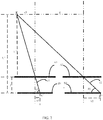
- a first photographing module includes a first lens A1 and a first photosensitive device B1
- a first optical axis C1 of the first lens A1 is perpendicular to a plane of the first lens A1 and a plane of the first photosensitive device B1
- a first incident light e1 from a K point of the to-be-photographed object transmits thorough a center of the second lens A1, and a first image point K'is formed on the first photosensitive device B1.
- An included angle formed by the first incident line e1 and the first photosensitive device B1 is a first incident angle ⁇ 1.
- a second photographing module includes a second lens A2 and a second photosensitive device B2, and a second optical axis C2 of the second lens A2 is perpendicular to a plane of the second lens A2 and a plane of the second photosensitive device B2.
- a second incident light e2 from the K point of the to-be-photographed object transmits through a center of the second lens A2, and a second image point K"is formed on the second photosensitive device B2.
- An included angle formed by the second incident line e2 and the second photosensitive device B2 is a second incident angle ⁇ 2.
- the first optical axis C1 is parallel to the second optical axis C2, and f indicates a distance between the first lens A1 and the first photosensitive device B1.
- the distance between the first lens A1 and the first photosensitive device B1 is the same as that between the second lens A2 and the second photosensitive device B2, thus f also indicates the distance between the second lens A2 and the second photosensitive device B2.
- d indicates a distance between centers of the first lens A1 and the second lens A2, and L'indicates a vertical distance from the K point to the first photosensitive device B1, and a vertical distance from the K point to the second photosensitive device B2.
- x1 indicates a distance from the first image point K'to the center of the first photosensitive device B1
- x2 indicates a distance from the second image point K"to the center of the second photosensitive device B2
- a distance from the K point to the center of the first lens A1 is x3.
- L' indicates the vertical distance from the K point to the first lens A1, and the vertical distance from the K point to the second lens A2, and also indicates the vertical distance from the to-be-photographed object to the first lens A1, and the vertical distance from the to-be-photographed object to the second lens A2. If the vertical distance L"from the to-be-photographed object to the first photosensitive device B1 or to the second photosensitive device B2 needs to be obtained, L"can be obtained by adding f to L'.
- the equation (3) can be used to determine that the distance of the to-be-photographed object can be determined by step S101a.
- the equation (3) can be written into software. By using the equation, the distance of the to-be-photographed object can be calculated.
- the distance of the to-be-photographed object is determined according to incident angles each formed by a light and the photosensitive device of one of the two photographing modules, distances each between one of the image points and the photosensitive device for forming the one of the image points, and a distance between the centers of the lens of the two photographing modules, and the light is formed when a light from the point of the to-be-photographed object arrives the photosensitive device of the one of the two photographing modules after transmitting through the center of the lens of the one of the two photographing modules.
- L As the distance d between the centers of the first lens A1 and the second lens A2, the distance x1 from the first image point K'to the center of the first photosensitive device B1, the distance x2 from the second image point K"to the center of the second photosensitive device B2, the first incident angle ⁇ 1, and the second incident angle ⁇ 2 are known, thus L"can be determined.
- L" indicates the vertical distance from the K point to the first photosensitive device B1, and the vertical distance from the K point to the second photosensitive device B2, and can also indicate the vertical distance from the to-be-photographed object to the first photosensitive device B1, and the vertical distance from the to-be-photographed object to the second photosensitive device B2.
- the distance f between the first lens A1 and the first photosensitive device B1 (the distance f is also the distance between the second optical lens A2 and the second photosensitive device B2) is also known.
- step S102 can be executed.
- step S103 whether the variation is less than or equal to a preset value is determined. If yes, step S104 is executed, otherwise the procedure returns to step S101 to determine the distance of the to-be-photographed object at a next moment.
- the variation is less than or equal to the preset value, it indicates that at the first moment and the second moment, the distance of the to-be-photographed object stays unchanged or the change of the distance of the to-be-photographed object is very small, thus the automatic photographing function can be triggered.
- FIG. 3 is a schematic view of a photographing apparatus in accordance with an embodiment of the present disclosure.
- the photographing device 3 includes two photographing modules (a first photographing module 311 and a second photographing module 312), a distance determining module 313, a calculating module 314, and a determining module 315.
- the two photographing modules are configured to acquire images of a to-be-photographed object at a first moment and a second moment after a preset time interval, and further configured to photograph the to-be-photographed object when the determining module 315 determines that a variation is less than or equal to a preset value.
- the distance determining module 313 is configured to determine a distance of the to-be-photographed object at the first moment according to image points formed by a point of the to-be-photographed object on photosensitive devices of the two photographing modules (the first photographing module 311 and the second photographing module 312) at the first moment, and parameters of the two photographing modules (the first photographing module 311 and the second photographing module 312), and determine a distance of the to-be-photographed object at the second moment according to image points formed by the point of the to-be-photographed object on the photosensitive devices of the two photographing modules (the first photographing module 311 and the second photographing module 312) at the second moment, and the parameters of the two photographing modules (the first photographing module 311 and the second photographing module 312).
- a calculating module 314 is configured to calculate the variation between the distance of the to-be-photographed object at the first moment and the distance of the to-be-photographed object at the second moment
- the determining module 315 is configured to determine whether the variation calculated by the calculating module 314 is less than or equal to the preset value.
- the distance determining module 313 includes a first determining sub-module configured to determine the distance of the to-be-photographed object according to distances each from one of the image points to a center of the photosensitive device for forming the one of the image points, a distance between centers of lens of the two photographing modules (the first photographing module 311 and the second photographing module 312), and distances each between the lens and the photosensitive device of one of the two photographing modules (the first photographing module 311 and the second photographing module 312).
- L' indicates the distance of the to-be-photographed object
- d indicates a distance between centers of the lens of the two photographing modules (the first photographing module 311 and the second photographing module 312)
- each of x2 and x1 indicates a distance from one of the image points to the center of the photosensitive device for forming the one of the image points
- f indicates a distance between the lens and the photosensitive device of one of the two photographing modules (the first photographing module 311 and the second photographing module 312).
- the distance determining module 313 includes a second determining sub-module configured to determine the distance of the to-be-photographed object according to incident angles each formed by a light and the photosensitive device of one of the two photographing modules, distances each from one of the image points to a center of the photosensitive device for forming the one of the image points, and a distance between centers of the lens of the two photographing modules, and the light is formed when a light from the point arrives the photosensitive device of the one of the two photographing modules after transmitting through a center of the lens of the one of the two photographing modules.
- L indicates the distance of the to-be-photographed object
- d indicates the distance between the centers of the lens of the two photographing modules (the first photographing module 311 and the second photographing module 312)
- each of x2 and x1 indicates the distance from one of the image points to the center of the photosensitive device for forming the one of the image points
- each of ⁇ 2 and ⁇ 1 indicates an incident angle formed by a light and the photosensitive device of one of the two photographing modules (the first photographing module 311 and the second photographing module 312), and the light is formed when a light from the point arrives the photosensitive device of the one of the two photographing modules (the first photographing module 311 and the second photographing module 312) after transmitting through the center of the lens of the one of the two photographing modules (the first photographing module 311 and the second photographing module 312).
- FIG. 4 is a schematic view of a terminal in accordance with an embodiment of the present disclosure.
- the terminal can include but not limited to a mobile phone.
- the terminal 4 can include at least one processor 41 (for example, CPU), at least one communication bus 42, a memory 43, and two photographing modules 44.
- the communication bus 42 is configured to realize communication among these components.
- the memory 43 can be a high speed random-access memory, and can also be a non-volatile memory, for example, at least one disc memory.
- a set of program codes is stored in the memory 43.
- the processor 41 invokes the set of program codes stored in the memory 43 to execute following operations: using the two photographing modules 44 to acquire images of a to-be-photographed object at a first moment and a second moment after a preset time interval, and determining a distance of the to-be-photographed object according to image points formed by a point of the to-be-photographed object on photosensitive devices of the two photographing modules 44, and parameters of the two photographing modules 44; calculating a variation between the distance of the to-be-photographed object at the first moment and the distance of the to-be-photographed object at the second moment; determining whether the variation is less than or equal to a preset value; and photographing the to-be-photographed object when the variation is less than or equal to the preset value.
- the processor 41 being configured to determine the distance of the to-be-photographed object according to the image points formed by the point of the to-be-photographed object on the photosensitive devices of the two photographing modules 44, and the parameters of the two photographing modules 44 includes: determining the distance of the to-be-photographed object according to distances each from one of the image points to a center of the photosensitive device for forming the one of the image points, a distance between centers of lens of the two photographing modules 44, and distances each between the lens and the photosensitive device of one of the two photographing devices 44.
- L' indicates the distance of the to-be-photographed object
- d indicates a distance between centers of the lens of the two photographing modules 44
- each of x2 and x1 indicates a distance from one of the image points to the center of the photosensitive device for forming the one of the image points
- f indicates a distance between the lens and the photosensitive device of one of the two photographing modules 44.
- the processor 41 being configured to determine the distance of the to-be-photographed object according to the image points formed by the point of the to-be-photographed object on the photosensitive devices of the two photographing modules 44, and the parameters of the two photographing modules 44 includes: determining the distance of the to-be-photographed object according to incident angles each formed by a light and the photosensitive device of one of the two photographing modules 44, distances each from one of the image points to a center of the photosensitive device for forming the one of the image points, and a distance between centers of the lens of the two photographing modules 44, wherein the light is formed when a light from the point arrives the photosensitive device of the one of the two photographing modules after transmitting through the center of the lens of the one of the two photographing modules 44.
- L indicates the distance of the to-be-photographed object
- d indicates the distance between the centers of the lens of the two photographing modules 44
- each of x2 and x1 indicates the distance from one of the image points to the center of the photosensitive device for forming the one of the image points
- each of ⁇ 2 and ⁇ 1 indicates an incident angle formed by a light and the photosensitive device of the one of the two photographing modules 44, wherein the light is formed when a light from the point arrives the photosensitive device of the one of the two photographing modules after transmitting through the center of the lens of the one of the two photographing modules 44.
- the present disclosure uses two photographing modules to perform distance measurement, and automatic photographing can be realized according to motion status of a user, thus the operation is simple, user requirements can be satisfied, and user experience can be improved.
Landscapes
- Engineering & Computer Science (AREA)
- Physics & Mathematics (AREA)
- General Physics & Mathematics (AREA)
- Electromagnetism (AREA)
- Radar, Positioning & Navigation (AREA)
- Remote Sensing (AREA)
- Multimedia (AREA)
- Signal Processing (AREA)
- Computer Vision & Pattern Recognition (AREA)
- Theoretical Computer Science (AREA)
- Human Computer Interaction (AREA)
- Studio Devices (AREA)
- Measurement Of Optical Distance (AREA)
- Focusing (AREA)
- Cameras In General (AREA)
Claims (11)
- Automatisches Fotografierverfahren, Folgendes umfassend:Verwenden von zwei Fotografiermodulen (311, 312), um Abbildungen eines zu fotografierenden Gegenstands zu einem ersten Zeitpunkt und einem zweiten Zeitpunkt nach einem voreingestellten Zeitintervall aufzunehmen, und Bestimmen einer Entfernung (L') des zu fotografierenden Gegenstands gemäß Bildpunkten (K', K"), die durch einen Punkt (K) des zu fotografierenden Gegenstands auf lichtempfindlichen Vorrichtungen (B1, B2) der zwei Fotografiermodule (311, 312) ausgebildet sind, sowie von Parametern der zwei Fotografiermodule (311, 312);Berechnen einer Variation zwischen der Entfernung des zu fotografierenden Gegenstands zum ersten Zeitpunkt und der Entfernung des zu fotografierenden Gegenstands zum zweiten Zeitpunkt;Bestimmen, ob die Variation kleiner oder gleich einem voreingestellten Wert ist; undAuslösen einer automatischen Fotografierfunktion zum zweiten Zeitpunkt, um den zu fotografierenden Gegenstand nach dem Bestimmen, ob die Variation kleiner oder gleich dem voreingestellten Wert ist, zu fotografieren.
- Automatisches Fotografierverfahren nach Anspruch 1, wobei das Bestimmen der Entfernung des zu fotografierenden Gegenstands gemäß den Bildpunkten (K', K"), die durch den Punkt (K) des zu fotografierenden Gegenstands auf den lichtempfindlichen Vorrichtungen (B1, B2) der zwei Fotografiermodule (311, 312) ausgebildet sind, sowie der Parameter der zwei Fotografiermodule (311, 312) Folgendes umfasst:
Bestimmen der Entfernung des zu fotografierenden Gegenstands gemäß den Entfernungen von den jeweiligen Bildpunkten (K', K") zu einem Mittelpunkt der lichtempfindlichen Vorrichtung (B1, B2) zum Ausbilden des einen der Bildpunkte (K', K"), eines Abstands zwischen den Mittelpunkten von Linsen (A1, A2) der zwei Fotografiermodule (311, 312) und von Abständen zwischen der jeweiligen Linse (A1, A2) und der lichtempfindlichen Vorrichtung (B1, B2) von einem der zwei Fotografiermodule (311, 312). - Automatisches Fotografierverfahren nach Anspruch 2, wobei die Entfernung des zu fotografierenden Gegenstands gemäß der folgenden Gleichung berechnet wird:

- Automatisches Fotografierverfahren nach Anspruch 1, wobei das Bestimmen der Entfernung des zu fotografierenden Gegenstands gemäß den Bildpunkten (K', K"), die durch den Punkt (K) des zu fotografierenden Gegenstands auf den lichtempfindlichen Vorrichtungen (B1, B2) der zwei Fotografiermodule (311, 312) ausgebildet sind, sowie der Parameter der zwei Fotografiermodule (311, 312) Folgendes umfasst:
Bestimmen der Entfernung des zu fotografierenden Gegenstands gemäß Einfallswinkeln, die durch ein Licht ausgebildet sind, und der lichtempfindlichen Vorrichtung (B1, B2) von einem der zwei Fotografiermodule (311, 312), der jeweiligen Entfernung von einem der Bildpunkte (K', K") zu einem Mittelpunkt der lichtempfindlichen Vorrichtung (B1, B2) zum Ausbilden des einen der Bildpunkte (K', K"), und der Entfernung zwischen den Mittelpunkten der Linsen (A1, A2) der zwei Fotografiermodule (311, 312), wobei das Licht ausgebildet wird, wenn ein Licht vom Punkt (K) des zu fotografierenden Gegenstands die lichtempfindliche Vorrichtung (B1, B2) des einen der zwei Fotografiermodule (311, 312) erreicht, nachdem es durch den Mittelpunkt der Linse (A1, A2) des einen der zwei Fotografiermodule (311, 312) hindurchgelassen wurde. - Automatisches Fotografierverfahren nach Anspruch 4, wobei die Entfernung des zu fotografierenden Gegenstands gemäß der folgenden Gleichung erhalten wird:

- Automatische Fotografiervorrichtung (3), Folgendes umfassend:zwei Fotografiermodule (311, 312), die konfiguriert sind, um Abbildungen eines zu fotografierenden Gegenstands zu einem ersten Zeitpunkt und einem zweiten Zeitpunkt nach einem voreingestellten Zeitintervall aufzunehmen,ein Entfernungsbestimmungsmodul (313), das konfiguriert ist, um eine Entfernung des zu fotografierenden Gegenstands zum ersten Zeitpunkt gemäß Bildpunkten (K', K"), die durch einen Punkt (K) des zu fotografierenden Gegenstands auf lichtempfindlichen Vorrichtungen (B1, B2) der zwei Fotografiermodule (311, 312) zum ersten Zeitpunkt ausgebildet sind, sowie Parameter der zwei Fotografiermodule (311, 212) zu bestimmen, und eine Entfernung des zu fotografierenden Gegenstands zum zweiten Zeitpunkt gemäß Bildpunkten (K', K"), die durch den Punkt (K) des zu fotografierenden Gegenstands auf den lichtempfindlichen Vorrichtungen (B1, B2) der zwei Fotografiermodule (311, 312) zum zweiten Zeitpunkt ausgebildet sind, sowie die Parameter der zwei Fotografiermodule (311, 212) zu bestimmen;ein Berechnungsmodul (314), das konfiguriert ist, um eine Variation zwischen der Entfernung des zu fotografierenden Gegenstands zum ersten Zeitpunkt und der Entfernung des zu fotografierenden Gegenstands zum zweiten Zeitpunkt zu berechnen; undein Bestimmungsmodul (315), das konfiguriert ist, um zu bestimmen, ob die Variation kleiner oder gleich einem voreingestellten Wert ist; undwobei die Fotografiermodule (311, 312) eine automatische Fotografierfunktion zum automatischen Fotografieren des zu fotografierenden Gegenstands umfassen, wobei die automatische Fotografierfunktion dadurch ausgelöst wird, dass das Bestimmungsmodul bestimmt, dass die Variation kleiner oder gleich dem voreingestellten Wert ist.
- Automatische Fotografiervorrichtung (3) nach Anspruch 6, wobei das Entfernungsbestimmungsmodul (313) Folgendes umfasst:
ein erstes Bestimmungssubmodul, das konfiguriert ist, um die Entfernung des zu fotografierenden Gegenstands gemäß der jeweiligen Entfernung von einem der Bildpunkte (K', K") zum Mittelpunkt der entsprechenden lichtempfindlichen Vorrichtung (B1, B2) zum Ausbilden des einen der Bildpunkte, einen Abstand zwischen den Mittelpunkten von Linsen (A1, A2) der zwei Fotografiermodule (311, 312) und den Abstand zwischen den Linsen (A1, A2) und der lichtempfindlichen Vorrichtung (B1, B2) von jeweils einem der zwei Fotografiermodule (311, 312) zu bestimmen. - Automatische Fotografiervorrichtung (3) nach Anspruch 7, wobei das erste Bestimmungssubmodul konfiguriert ist, um die Entfernung des zu fotografierenden Gegenstands gemäß der folgenden Gleichung zu berechnen:

- Automatische Fotografiervorrichtung (3) nach Anspruch 6, wobei das Entfernungsbestimmungsmodul Folgendes umfasst:
ein zweites Bestimmungssubmodul, das konfiguriert ist, um die Entfernung des zu fotografierenden Gegenstands gemäß Einfallswinkeln, die jeweils durch ein Licht ausgebildet sind, und der lichtempfindlichen Vorrichtung (B1, B2) von einem der zwei Fotografiermodule (311, 312), die jeweilige Entfernung von einem der Bildpunkte (K', K") zu einem Mittelpunkt der entsprechenden lichtempfindlichen Vorrichtung (B1, B2) zum Ausbilden des einen der Bildpunkte (K', K"), und die Entfernung zwischen den Mittelpunkten der Linsen (A1, A2) der zwei Fotografiermodule (311, 312) zu bestimmen, wobei das Licht ausgebildet wird, wenn ein Licht vom Punkt (K) des zu fotografierenden Gegenstands die lichtempfindliche Vorrichtung (B1, B2) des einen der zwei Fotografiermodule (311, 312) erreicht, nachdem es durch den Mittelpunkt der Linse (A1, A2) des einen der zwei Fotografiermodule (311, 312) hindurchgelassen wurde. - Automatische Fotografiervorrichtung (3) nach Anspruch 9, wobei das zweite Bestimmungssubmodul konfiguriert ist, um die Entfernung des zu fotografierenden Gegenstands gemäß der folgenden Gleichung zu berechnen:

- Endgerät (4), Folgendes umfassend:einen Speicher (43), der einen Satz von Programmkodes speichert;zwei Fotografiermodule (44, 311, 312); undeinen Prozessor (41), der konfiguriert ist, um den Satz von auf dem Speicher (43) gespeicherten Programmkodes abzurufen, um ein automatisches Verfahren nach einem der Ansprüche 1 bis 5 auszuführen.
Applications Claiming Priority (2)
| Application Number | Priority Date | Filing Date | Title |
|---|---|---|---|
| CN201510026519.1A CN104580912B (zh) | 2015-01-19 | 2015-01-19 | 一种拍摄方法、装置及终端 |
| PCT/CN2015/082857 WO2016115832A1 (zh) | 2015-01-19 | 2015-06-30 | 一种拍摄方法、装置及终端 |
Publications (3)
| Publication Number | Publication Date |
|---|---|
| EP3154256A1 EP3154256A1 (de) | 2017-04-12 |
| EP3154256A4 EP3154256A4 (de) | 2018-01-17 |
| EP3154256B1 true EP3154256B1 (de) | 2019-08-07 |
Family
ID=53096009
Family Applications (1)
| Application Number | Title | Priority Date | Filing Date |
|---|---|---|---|
| EP15878504.8A Active EP3154256B1 (de) | 2015-01-19 | 2015-06-30 | Verfahren, vorrichtung und terminal für automatisches fotografieren |
Country Status (4)
| Country | Link |
|---|---|
| US (1) | US10339415B2 (de) |
| EP (1) | EP3154256B1 (de) |
| CN (1) | CN104580912B (de) |
| WO (1) | WO2016115832A1 (de) |
Families Citing this family (3)
| Publication number | Priority date | Publication date | Assignee | Title |
|---|---|---|---|---|
| CN104580912B (zh) * | 2015-01-19 | 2018-01-09 | 宇龙计算机通信科技(深圳)有限公司 | 一种拍摄方法、装置及终端 |
| CN105681667A (zh) * | 2016-02-29 | 2016-06-15 | 广东欧珀移动通信有限公司 | 控制方法、控制装置及电子装置 |
| EP3569993A1 (de) * | 2018-05-16 | 2019-11-20 | BSH Hausgeräte GmbH | Verfahren und scanning-vorrichtung zur bestimmung von spektralen daten |
Family Cites Families (18)
| Publication number | Priority date | Publication date | Assignee | Title |
|---|---|---|---|---|
| JPH0812073B2 (ja) * | 1990-09-03 | 1996-02-07 | 三菱電機株式会社 | 車間距離検出装置 |
| US5640224A (en) * | 1992-01-28 | 1997-06-17 | Nikon Corporation | Automatic photographing apparatus in a camera |
| AU668470B2 (en) * | 1993-07-12 | 1996-05-02 | Seaward International, Inc. | Elongated structural member and method and apparatus for making same |
| JP4004591B2 (ja) * | 1997-04-18 | 2007-11-07 | オリンパス株式会社 | セルフモード機能付カメラ |
| JP4800163B2 (ja) * | 2006-09-29 | 2011-10-26 | 株式会社トプコン | 位置測定装置及びその方法 |
| US7676146B2 (en) * | 2007-03-09 | 2010-03-09 | Eastman Kodak Company | Camera using multiple lenses and image sensors to provide improved focusing capability |
| JP5060233B2 (ja) | 2007-09-25 | 2012-10-31 | 富士フイルム株式会社 | 撮像装置およびその自動撮影方法 |
| JP4438099B2 (ja) * | 2007-11-22 | 2010-03-24 | カシオ計算機株式会社 | 撮像装置及びそのプログラム |
| JP4986175B2 (ja) * | 2007-12-28 | 2012-07-25 | カシオ計算機株式会社 | 撮像装置及びプログラム |
| JP5870510B2 (ja) * | 2010-09-14 | 2016-03-01 | 株式会社リコー | ステレオカメラ装置、校正方法およびプログラム |
| CN102062596A (zh) * | 2010-11-12 | 2011-05-18 | 中兴通讯股份有限公司 | 一种利用双摄像头测距的方法和装置 |
| CN102158645A (zh) * | 2011-01-11 | 2011-08-17 | 华为终端有限公司 | 拍摄控制方法、拍摄控制装置和摄像装置 |
| CN102620713A (zh) * | 2012-03-26 | 2012-08-01 | 梁寿昌 | 一种利用双摄像头测距和定位的方法 |
| CN102710865A (zh) * | 2012-06-18 | 2012-10-03 | 宇龙计算机通信科技(深圳)有限公司 | 具有拍照功能的移动终端及其人像自拍方法 |
| EP3073733A4 (de) * | 2013-12-06 | 2017-04-05 | Huawei Device Co., Ltd. | Verfahren zur erzeugung von bildern und doppellinsenvorrichtung |
| CN104159037A (zh) * | 2014-08-26 | 2014-11-19 | 厦门美图之家科技有限公司 | 一种自动拍照的自拍方法 |
| CN105806320B (zh) * | 2014-12-29 | 2020-04-21 | 同方威视技术股份有限公司 | 拍摄测量系统以及拍摄测量方法 |
| CN104580912B (zh) * | 2015-01-19 | 2018-01-09 | 宇龙计算机通信科技(深圳)有限公司 | 一种拍摄方法、装置及终端 |
-
2015
- 2015-01-19 CN CN201510026519.1A patent/CN104580912B/zh active Active
- 2015-06-30 WO PCT/CN2015/082857 patent/WO2016115832A1/zh not_active Ceased
- 2015-06-30 US US15/324,575 patent/US10339415B2/en active Active
- 2015-06-30 EP EP15878504.8A patent/EP3154256B1/de active Active
Non-Patent Citations (1)
| Title |
|---|
| None * |
Also Published As
| Publication number | Publication date |
|---|---|
| WO2016115832A1 (zh) | 2016-07-28 |
| US10339415B2 (en) | 2019-07-02 |
| US20170213106A1 (en) | 2017-07-27 |
| CN104580912B (zh) | 2018-01-09 |
| EP3154256A4 (de) | 2018-01-17 |
| EP3154256A1 (de) | 2017-04-12 |
| CN104580912A (zh) | 2015-04-29 |
Similar Documents
| Publication | Publication Date | Title |
|---|---|---|
| CN103246130B (zh) | 一种对焦方法及装置 | |
| US9703175B2 (en) | Systems and methods for autofocus trigger | |
| CN105635555B (zh) | 摄像头聚焦控制方法、摄像设备和可穿戴式智能终端 | |
| EP3163394A1 (de) | Verfahren und vorrichtung zur steuerung eines unbemannten luftfahrzeugs | |
| WO2019037088A1 (zh) | 一种曝光的控制方法、装置以及无人机 | |
| KR20140140855A (ko) | 촬영 장치의 자동 초점 조절 방법 및 장치 | |
| KR20170056698A (ko) | 자동 포커싱 방법, 장치 및 전자 장치 | |
| CN104104870B (zh) | 拍摄控制方法、拍摄控制装置及拍摄设备 | |
| EP3796638B1 (de) | Linsensteuerungsverfahren und -vorrichtung und terminal | |
| US12535179B2 (en) | Control method based on image capturing apparatus, control method and apparatus for gimbal | |
| KR20160091246A (ko) | 자동 핀트 맞춤 방법, 장치, 프로그램 및 기록매체 | |
| CN106597424A (zh) | 一种基于双摄像头的测距方法、系统及移动终端 | |
| CN105282420A (zh) | 拍摄的实现方法及装置 | |
| CN110058474B (zh) | 可换镜头 | |
| US10339415B2 (en) | Photographing method and apparatus and terminal | |
| WO2021184239A1 (zh) | 曝光方法、装置、拍摄设备、可移动平台和存储介质 | |
| JP7377614B2 (ja) | ウェアラブル装置および送信制御方法 | |
| US8014663B2 (en) | Camera, accessory, and camera system | |
| US20130300920A1 (en) | Lens-interchangeable camera system, lens data transmission method and lens data acquisition program | |
| JP2013162348A (ja) | 撮像装置 | |
| CN106558078B (zh) | 一种双目立体视觉摄像机及其摄像方法 | |
| JP7263493B2 (ja) | 電子機器及び通知方法 | |
| US9723189B2 (en) | Portable electronic-devices and methods for image extraction | |
| CN105700111B (zh) | 一种移动终端的自动对焦方法、装置及移动终端 | |
| CN106303256A (zh) | 一种拍摄参数的确定方法及装置 |
Legal Events
| Date | Code | Title | Description |
|---|---|---|---|
| STAA | Information on the status of an ep patent application or granted ep patent |
Free format text: STATUS: THE INTERNATIONAL PUBLICATION HAS BEEN MADE |
|
| PUAI | Public reference made under article 153(3) epc to a published international application that has entered the european phase |
Free format text: ORIGINAL CODE: 0009012 |
|
| STAA | Information on the status of an ep patent application or granted ep patent |
Free format text: STATUS: REQUEST FOR EXAMINATION WAS MADE |
|
| 17P | Request for examination filed |
Effective date: 20170106 |
|
| AK | Designated contracting states |
Kind code of ref document: A1 Designated state(s): AL AT BE BG CH CY CZ DE DK EE ES FI FR GB GR HR HU IE IS IT LI LT LU LV MC MK MT NL NO PL PT RO RS SE SI SK SM TR |
|
| AX | Request for extension of the european patent |
Extension state: BA ME |
|
| A4 | Supplementary search report drawn up and despatched |
Effective date: 20171219 |
|
| RIC1 | Information provided on ipc code assigned before grant |
Ipc: H04N 5/225 20060101ALI20171213BHEP Ipc: H04N 5/232 20060101AFI20171213BHEP Ipc: G01C 3/00 20060101ALI20171213BHEP Ipc: G06T 7/73 20170101ALI20171213BHEP Ipc: G06K 9/62 20060101ALI20171213BHEP Ipc: G01C 3/14 20060101ALI20171213BHEP |
|
| DAV | Request for validation of the european patent (deleted) | ||
| DAX | Request for extension of the european patent (deleted) | ||
| GRAP | Despatch of communication of intention to grant a patent |
Free format text: ORIGINAL CODE: EPIDOSNIGR1 |
|
| STAA | Information on the status of an ep patent application or granted ep patent |
Free format text: STATUS: GRANT OF PATENT IS INTENDED |
|
| GRAS | Grant fee paid |
Free format text: ORIGINAL CODE: EPIDOSNIGR3 |
|
| INTG | Intention to grant announced |
Effective date: 20190605 |
|
| RIN1 | Information on inventor provided before grant (corrected) |
Inventor name: DU, LIJIAN |
|
| GRAA | (expected) grant |
Free format text: ORIGINAL CODE: 0009210 |
|
| STAA | Information on the status of an ep patent application or granted ep patent |
Free format text: STATUS: THE PATENT HAS BEEN GRANTED |
|
| AK | Designated contracting states |
Kind code of ref document: B1 Designated state(s): AL AT BE BG CH CY CZ DE DK EE ES FI FR GB GR HR HU IE IS IT LI LT LU LV MC MK MT NL NO PL PT RO RS SE SI SK SM TR |
|
| REG | Reference to a national code |
Ref country code: GB Ref legal event code: FG4D |
|
| REG | Reference to a national code |
Ref country code: CH Ref legal event code: EP Ref country code: AT Ref legal event code: REF Ref document number: 1165653 Country of ref document: AT Kind code of ref document: T Effective date: 20190815 |
|
| REG | Reference to a national code |
Ref country code: DE Ref legal event code: R096 Ref document number: 602015035609 Country of ref document: DE |
|
| REG | Reference to a national code |
Ref country code: IE Ref legal event code: FG4D |
|
| REG | Reference to a national code |
Ref country code: NL Ref legal event code: FP |
|
| REG | Reference to a national code |
Ref country code: LT Ref legal event code: MG4D |
|
| PG25 | Lapsed in a contracting state [announced via postgrant information from national office to epo] |
Ref country code: LT Free format text: LAPSE BECAUSE OF FAILURE TO SUBMIT A TRANSLATION OF THE DESCRIPTION OR TO PAY THE FEE WITHIN THE PRESCRIBED TIME-LIMIT Effective date: 20190807 Ref country code: HR Free format text: LAPSE BECAUSE OF FAILURE TO SUBMIT A TRANSLATION OF THE DESCRIPTION OR TO PAY THE FEE WITHIN THE PRESCRIBED TIME-LIMIT Effective date: 20190807 Ref country code: FI Free format text: LAPSE BECAUSE OF FAILURE TO SUBMIT A TRANSLATION OF THE DESCRIPTION OR TO PAY THE FEE WITHIN THE PRESCRIBED TIME-LIMIT Effective date: 20190807 Ref country code: BG Free format text: LAPSE BECAUSE OF FAILURE TO SUBMIT A TRANSLATION OF THE DESCRIPTION OR TO PAY THE FEE WITHIN THE PRESCRIBED TIME-LIMIT Effective date: 20191107 Ref country code: PT Free format text: LAPSE BECAUSE OF FAILURE TO SUBMIT A TRANSLATION OF THE DESCRIPTION OR TO PAY THE FEE WITHIN THE PRESCRIBED TIME-LIMIT Effective date: 20191209 Ref country code: NO Free format text: LAPSE BECAUSE OF FAILURE TO SUBMIT A TRANSLATION OF THE DESCRIPTION OR TO PAY THE FEE WITHIN THE PRESCRIBED TIME-LIMIT Effective date: 20191107 Ref country code: SE Free format text: LAPSE BECAUSE OF FAILURE TO SUBMIT A TRANSLATION OF THE DESCRIPTION OR TO PAY THE FEE WITHIN THE PRESCRIBED TIME-LIMIT Effective date: 20190807 |
|
| REG | Reference to a national code |
Ref country code: AT Ref legal event code: MK05 Ref document number: 1165653 Country of ref document: AT Kind code of ref document: T Effective date: 20190807 |
|
| PG25 | Lapsed in a contracting state [announced via postgrant information from national office to epo] |
Ref country code: RS Free format text: LAPSE BECAUSE OF FAILURE TO SUBMIT A TRANSLATION OF THE DESCRIPTION OR TO PAY THE FEE WITHIN THE PRESCRIBED TIME-LIMIT Effective date: 20190807 Ref country code: GR Free format text: LAPSE BECAUSE OF FAILURE TO SUBMIT A TRANSLATION OF THE DESCRIPTION OR TO PAY THE FEE WITHIN THE PRESCRIBED TIME-LIMIT Effective date: 20191108 Ref country code: IS Free format text: LAPSE BECAUSE OF FAILURE TO SUBMIT A TRANSLATION OF THE DESCRIPTION OR TO PAY THE FEE WITHIN THE PRESCRIBED TIME-LIMIT Effective date: 20191207 Ref country code: AL Free format text: LAPSE BECAUSE OF FAILURE TO SUBMIT A TRANSLATION OF THE DESCRIPTION OR TO PAY THE FEE WITHIN THE PRESCRIBED TIME-LIMIT Effective date: 20190807 Ref country code: LV Free format text: LAPSE BECAUSE OF FAILURE TO SUBMIT A TRANSLATION OF THE DESCRIPTION OR TO PAY THE FEE WITHIN THE PRESCRIBED TIME-LIMIT Effective date: 20190807 Ref country code: ES Free format text: LAPSE BECAUSE OF FAILURE TO SUBMIT A TRANSLATION OF THE DESCRIPTION OR TO PAY THE FEE WITHIN THE PRESCRIBED TIME-LIMIT Effective date: 20190807 |
|
| PG25 | Lapsed in a contracting state [announced via postgrant information from national office to epo] |
Ref country code: TR Free format text: LAPSE BECAUSE OF FAILURE TO SUBMIT A TRANSLATION OF THE DESCRIPTION OR TO PAY THE FEE WITHIN THE PRESCRIBED TIME-LIMIT Effective date: 20190807 |
|
| PG25 | Lapsed in a contracting state [announced via postgrant information from national office to epo] |
Ref country code: DK Free format text: LAPSE BECAUSE OF FAILURE TO SUBMIT A TRANSLATION OF THE DESCRIPTION OR TO PAY THE FEE WITHIN THE PRESCRIBED TIME-LIMIT Effective date: 20190807 Ref country code: AT Free format text: LAPSE BECAUSE OF FAILURE TO SUBMIT A TRANSLATION OF THE DESCRIPTION OR TO PAY THE FEE WITHIN THE PRESCRIBED TIME-LIMIT Effective date: 20190807 Ref country code: PL Free format text: LAPSE BECAUSE OF FAILURE TO SUBMIT A TRANSLATION OF THE DESCRIPTION OR TO PAY THE FEE WITHIN THE PRESCRIBED TIME-LIMIT Effective date: 20190807 Ref country code: EE Free format text: LAPSE BECAUSE OF FAILURE TO SUBMIT A TRANSLATION OF THE DESCRIPTION OR TO PAY THE FEE WITHIN THE PRESCRIBED TIME-LIMIT Effective date: 20190807 Ref country code: IT Free format text: LAPSE BECAUSE OF FAILURE TO SUBMIT A TRANSLATION OF THE DESCRIPTION OR TO PAY THE FEE WITHIN THE PRESCRIBED TIME-LIMIT Effective date: 20190807 Ref country code: RO Free format text: LAPSE BECAUSE OF FAILURE TO SUBMIT A TRANSLATION OF THE DESCRIPTION OR TO PAY THE FEE WITHIN THE PRESCRIBED TIME-LIMIT Effective date: 20190807 |
|
| PG25 | Lapsed in a contracting state [announced via postgrant information from national office to epo] |
Ref country code: SM Free format text: LAPSE BECAUSE OF FAILURE TO SUBMIT A TRANSLATION OF THE DESCRIPTION OR TO PAY THE FEE WITHIN THE PRESCRIBED TIME-LIMIT Effective date: 20190807 Ref country code: IS Free format text: LAPSE BECAUSE OF FAILURE TO SUBMIT A TRANSLATION OF THE DESCRIPTION OR TO PAY THE FEE WITHIN THE PRESCRIBED TIME-LIMIT Effective date: 20200224 Ref country code: SK Free format text: LAPSE BECAUSE OF FAILURE TO SUBMIT A TRANSLATION OF THE DESCRIPTION OR TO PAY THE FEE WITHIN THE PRESCRIBED TIME-LIMIT Effective date: 20190807 Ref country code: CZ Free format text: LAPSE BECAUSE OF FAILURE TO SUBMIT A TRANSLATION OF THE DESCRIPTION OR TO PAY THE FEE WITHIN THE PRESCRIBED TIME-LIMIT Effective date: 20190807 |
|
| REG | Reference to a national code |
Ref country code: DE Ref legal event code: R097 Ref document number: 602015035609 Country of ref document: DE |
|
| PLBE | No opposition filed within time limit |
Free format text: ORIGINAL CODE: 0009261 |
|
| STAA | Information on the status of an ep patent application or granted ep patent |
Free format text: STATUS: NO OPPOSITION FILED WITHIN TIME LIMIT |
|
| PG2D | Information on lapse in contracting state deleted |
Ref country code: IS |
|
| 26N | No opposition filed |
Effective date: 20200603 |
|
| PG25 | Lapsed in a contracting state [announced via postgrant information from national office to epo] |
Ref country code: SI Free format text: LAPSE BECAUSE OF FAILURE TO SUBMIT A TRANSLATION OF THE DESCRIPTION OR TO PAY THE FEE WITHIN THE PRESCRIBED TIME-LIMIT Effective date: 20190807 |
|
| PG25 | Lapsed in a contracting state [announced via postgrant information from national office to epo] |
Ref country code: MC Free format text: LAPSE BECAUSE OF FAILURE TO SUBMIT A TRANSLATION OF THE DESCRIPTION OR TO PAY THE FEE WITHIN THE PRESCRIBED TIME-LIMIT Effective date: 20190807 |
|
| REG | Reference to a national code |
Ref country code: CH Ref legal event code: PL |
|
| PG25 | Lapsed in a contracting state [announced via postgrant information from national office to epo] |
Ref country code: LU Free format text: LAPSE BECAUSE OF NON-PAYMENT OF DUE FEES Effective date: 20200630 |
|
| REG | Reference to a national code |
Ref country code: BE Ref legal event code: MM Effective date: 20200630 |
|
| PG25 | Lapsed in a contracting state [announced via postgrant information from national office to epo] |
Ref country code: LI Free format text: LAPSE BECAUSE OF NON-PAYMENT OF DUE FEES Effective date: 20200630 Ref country code: IE Free format text: LAPSE BECAUSE OF NON-PAYMENT OF DUE FEES Effective date: 20200630 Ref country code: CH Free format text: LAPSE BECAUSE OF NON-PAYMENT OF DUE FEES Effective date: 20200630 |
|
| PG25 | Lapsed in a contracting state [announced via postgrant information from national office to epo] |
Ref country code: BE Free format text: LAPSE BECAUSE OF NON-PAYMENT OF DUE FEES Effective date: 20200630 |
|
| PG25 | Lapsed in a contracting state [announced via postgrant information from national office to epo] |
Ref country code: MT Free format text: LAPSE BECAUSE OF FAILURE TO SUBMIT A TRANSLATION OF THE DESCRIPTION OR TO PAY THE FEE WITHIN THE PRESCRIBED TIME-LIMIT Effective date: 20190807 Ref country code: CY Free format text: LAPSE BECAUSE OF FAILURE TO SUBMIT A TRANSLATION OF THE DESCRIPTION OR TO PAY THE FEE WITHIN THE PRESCRIBED TIME-LIMIT Effective date: 20190807 |
|
| PG25 | Lapsed in a contracting state [announced via postgrant information from national office to epo] |
Ref country code: MK Free format text: LAPSE BECAUSE OF FAILURE TO SUBMIT A TRANSLATION OF THE DESCRIPTION OR TO PAY THE FEE WITHIN THE PRESCRIBED TIME-LIMIT Effective date: 20190807 |
|
| REG | Reference to a national code |
Ref country code: DE Ref legal event code: R079 Ref document number: 602015035609 Country of ref document: DE Free format text: PREVIOUS MAIN CLASS: H04N0005232000 Ipc: H04N0023600000 |
|
| PGFP | Annual fee paid to national office [announced via postgrant information from national office to epo] |
Ref country code: NL Payment date: 20250528 Year of fee payment: 11 |
|
| PGFP | Annual fee paid to national office [announced via postgrant information from national office to epo] |
Ref country code: DE Payment date: 20250617 Year of fee payment: 11 |
|
| PGFP | Annual fee paid to national office [announced via postgrant information from national office to epo] |
Ref country code: GB Payment date: 20250625 Year of fee payment: 11 |
|
| PGFP | Annual fee paid to national office [announced via postgrant information from national office to epo] |
Ref country code: FR Payment date: 20250630 Year of fee payment: 11 |