EP3148917B1 - Befestigungsvorrichtung zum befestigen einer palette an einem zugmittel - Google Patents
Befestigungsvorrichtung zum befestigen einer palette an einem zugmittel Download PDFInfo
- Publication number
- EP3148917B1 EP3148917B1 EP15721278.8A EP15721278A EP3148917B1 EP 3148917 B1 EP3148917 B1 EP 3148917B1 EP 15721278 A EP15721278 A EP 15721278A EP 3148917 B1 EP3148917 B1 EP 3148917B1
- Authority
- EP
- European Patent Office
- Prior art keywords
- chain
- link
- chain link
- cup
- plate belt
- Prior art date
- Legal status (The legal status is an assumption and is not a legal conclusion. Google has not performed a legal analysis and makes no representation as to the accuracy of the status listed.)
- Active
Links
Images

Classifications
-
- B—PERFORMING OPERATIONS; TRANSPORTING
- B65—CONVEYING; PACKING; STORING; HANDLING THIN OR FILAMENTARY MATERIAL
- B65G—TRANSPORT OR STORAGE DEVICES, e.g. CONVEYORS FOR LOADING OR TIPPING, SHOP CONVEYOR SYSTEMS OR PNEUMATIC TUBE CONVEYORS
- B65G17/00—Conveyors having an endless traction element, e.g. a chain, transmitting movement to a continuous or substantially-continuous load-carrying surface or to a series of individual load-carriers; Endless-chain conveyors in which the chains form the load-carrying surface
- B65G17/06—Conveyors having an endless traction element, e.g. a chain, transmitting movement to a continuous or substantially-continuous load-carrying surface or to a series of individual load-carriers; Endless-chain conveyors in which the chains form the load-carrying surface having a load-carrying surface formed by a series of interconnected, e.g. longitudinal, links, plates, or platforms
- B65G17/067—Conveyors having an endless traction element, e.g. a chain, transmitting movement to a continuous or substantially-continuous load-carrying surface or to a series of individual load-carriers; Endless-chain conveyors in which the chains form the load-carrying surface having a load-carrying surface formed by a series of interconnected, e.g. longitudinal, links, plates, or platforms the load carrying surface being formed by plates or platforms attached to more than one traction element
-
- B—PERFORMING OPERATIONS; TRANSPORTING
- B65—CONVEYING; PACKING; STORING; HANDLING THIN OR FILAMENTARY MATERIAL
- B65G—TRANSPORT OR STORAGE DEVICES, e.g. CONVEYORS FOR LOADING OR TIPPING, SHOP CONVEYOR SYSTEMS OR PNEUMATIC TUBE CONVEYORS
- B65G39/00—Rollers, e.g. drive rollers, or arrangements thereof incorporated in roller-ways or other types of mechanical conveyors
- B65G39/10—Arrangements of rollers
- B65G39/20—Arrangements of rollers attached to moving belts or chains
-
- B—PERFORMING OPERATIONS; TRANSPORTING
- B66—HOISTING; LIFTING; HAULING
- B66B—ELEVATORS; ESCALATORS OR MOVING WALKWAYS
- B66B23/00—Component parts of escalators or moving walkways
- B66B23/08—Carrying surfaces
- B66B23/10—Carrying belts
-
- B—PERFORMING OPERATIONS; TRANSPORTING
- B66—HOISTING; LIFTING; HAULING
- B66B—ELEVATORS; ESCALATORS OR MOVING WALKWAYS
- B66B23/00—Component parts of escalators or moving walkways
- B66B23/14—Guiding means for carrying surfaces
-
- B—PERFORMING OPERATIONS; TRANSPORTING
- B66—HOISTING; LIFTING; HAULING
- B66B—ELEVATORS; ESCALATORS OR MOVING WALKWAYS
- B66B23/00—Component parts of escalators or moving walkways
- B66B23/14—Guiding means for carrying surfaces
- B66B23/145—Roller assemblies
-
- B—PERFORMING OPERATIONS; TRANSPORTING
- B66—HOISTING; LIFTING; HAULING
- B66B—ELEVATORS; ESCALATORS OR MOVING WALKWAYS
- B66B29/00—Safety devices of escalators or moving walkways
- B66B29/005—Applications of security monitors
Definitions
- the invention relates to a fastening device for connecting a pallet of a moving walkway with a link chain serving as a traction means.
- Moving walkways are well-known and efficient means of transporting people. They are typically used for transporting persons in the horizontal direction, but also in the vertical direction with a slight incline of up to 12 °, for example when carrying users with shopping carts from one floor of a building to another floor. The length and width of the moving walk are selected depending on the expected passenger traffic for each application.
- Pallets are designed as one-piece or multi-part components and their parts usually produced by casting, extrusion, forging and the like.
- Several pallets are usually connected by means of two traction means to a pallet band of a moving walk.
- these traction devices are articulated chains.
- a moving walkway usually has a supporting structure or truss with two deflection areas, between which the pallet belt is guided circumferentially.
- connection between the articulated chain and the pallet must be secure and durable, since disengaging the connection and thus the pallet from the pallet band during operation of the moving walkway can have catastrophic consequences for the users.
- Object of the present invention is therefore to provide a fastening device for connecting a pallet with serving as a traction means hinge chains, which is easy to install, inexpensive to manufacture and in the assembled state or in operation in a simple manner verifiable.
- a pallet strip of a moving walk with pallets arranged one behind the other in the direction of movement, which are arranged between two mutually parallel, formed of different widths chain links link chains.
- Each chain link is connected to one of the pallets by means of at least one fastening device.
- the fastening device has a fastening bolt and a cup wheel, wherein the cup wheel includes a cup bottom ring and a cup rim surrounding the cup bottom ring or pot collar.
- the inner height of the pot edge corresponds to the thickness of at least one link plate of the chain link.
- the inner diameter of the pot edge is greater than the outer diameter of the fitting in the mounted state on the pot bottom ring portion of the fastening bolt.
- the cup wheel with its tuned to the thickness of the link plate inner height and with its matched to the mounting bolt inner diameter allows the same fastening device between narrow and wide links of the articulated chain and the pallets to be attached can be used. Furthermore, the use of the cup wheel also causes all parts of the fastening device remain visible and all bolt ends of the fastening bolts of a pallet strip protrude the same distance from the joints between the articulated chain and pallets. This feature allows a very reliable and easy visual inspection of all fasteners one pallet band, since neither the cup wheel nor the end of the mounting bolt are completely hidden by areas of the articulated chain and / or the pallet. As soon as the bolt end of a fastening bolt projects beyond the other bolt ends of the pallet band, this is immediately recognizable. Of course, the verification of the bolt ends can also be done by means of sensors, wherein per bolt end row of a pallet belt only one sensor is required.
- the verification of the bolt ends is particularly simple if they from the side facing away from the pallets of the articulated chain reluctance their chain plate protrude. To achieve this, penetrates preferably in the mounted state of the fastening bolt at least two mutually parallel link plates of the chain link to be connected to the chain link.
- the cup wheel can be arranged between the bolt head of the fastening bolt and the pallet facing away from the chain link chain, that in narrow chain links the pot edge and wide chain links the Pot bottom ring rests against the link plate of each chain link.
- the link chains only narrow and wide chain links, which are arranged alternately below each other and connected to each other in the joints of the joint chain. If the cup wheels are arranged alternately on the articulated chain, that rests with narrow chain links the pot edge and wide chain links of the bottom ring pot on the link plate of each chain link, all bolt heads protrude equally neglecting the axial play of the joint chain out of the articulated chain.
- the pallet can be most easily attached directly to the articulated chain, when the fastening bolt penetrates a link facing the chain link of the pallet attached to this chain link or protrudes into a bore of the attached to this chain link pallet.
- the bore may for example be a through hole, a blind hole or a threaded blind hole.
- Other options include trained on the cheek grooves, slots, openings, openings and the like, so that the mounting bolt can penetrate the cheek.
- a spacer element can be arranged, the thickness of which corresponds to the thickness of a link plate.
- a thread may be formed, which is screwed into the above-mentioned threaded blind hole or, when the fastening bolt penetrates the cheek of the pallet, for example, receives a nut.
- the best assurance of detachable screw connections can be achieved so that the greatest possible elongation within the screw is available.
- Particularly advantageous in this case are the chain straps of a chain link penetrating fastening bolts. In these, the entire shaft length of the fastening bolt, which is present between the two outer link plates of a chain link, can be exploited as Dehnmother. But so that the chain links are not compressed laterally when tightening the fastening bolt, at least one support sleeve can be arranged between the two outer link plates of the respective chain link, through the bore of the fastening bolt can be pushed.
- each of the link chains may have rollers. These are preferably arranged in the region of the hinge points on the traction means. This has the advantage that the connecting bolts of the articulated chain used in the joints serve at the same time as roller axles.
- the rollers can be arranged between the link plates in the joints of the joint chain.
- each of the hinge chains may also have rollers which are arranged on the side facing away from the pallets outside of the chain links and thus the pallet band in the hinge points.
- damaged rollers can be replaced with new rollers on existing systems without having to remove the articulated chain, as is required in articulated chains with arranged between the chain links rollers.
- the fastening bolts preferably project laterally beyond the rollers.
- the fastening bolts projecting in the lateral direction out of the articulated chain, or extending orthogonally to the conveying direction of the pallet band, can additionally be used. Since the bolt ends (bolt heads and the bolt heads opposite bolt ends) of the fastening bolts are all in line with respect to the conveying direction, the fastening bolts can also be used as guide elements. There are various options for this. For example, a low sliding friction coefficient slider may be disposed at a bolt end of at least one fastening bolt. Of course, the bolt ends may also be coated, for example with a bonded coating or with a plastic coating. Another possibility would be to let in the bolt head a frontally outstanding trackball.
- the above-described pallet band can be used with the inventive fastening device not only in new moving walks.
- an existing moving walk can be modernized by replacing the existing pallet band with a pallet band according to the invention.
- At least one monitoring sensor can also be present, by means of which the position of one end of the fastening bolt relative to the position of a link plate of the associated chain link and relative to the ends of the other fastening bolts can be detected.
- both a defective fastening device, as well as the straight running of the pallet band can be detected simultaneously.
- the position of the ends can be scanned optically and / or mechanically, for example.
- monitoring sensors all possible detection devices such as CCD cameras, TOF cameras, photoelectric sensors, push button, laser scanning, inductive proximity switches and the like can be used more.
- the number of monitoring sensors preferably depends on the number of rows of fastening devices and thus on the number of traction means of a pallet band.
- the sensor signal of the monitoring sensor can be compared in a monitoring unit with a desired value or desired state.
- the monitoring unit then provides information, for example, to the moving walk control or to the safety circuit of the moving walk, whether the pallet band is allowed to circulate, or braked, or even blocked, in order to prevent accidents.
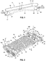
- FIG. 1 schematically shows in side view a moving walkway 11, which connects a first floor E1 with a second floor E2.
- the moving walk 11 could also connect two places on the same level, as is often the case in long corridors of airports.
- the moving walk 11 has a supporting structure 16 or truss 16 with two deflection areas 17, 18. In the deflection areas sprockets 27, 28 are arranged, between which a pallet belt 15 is guided circumferentially.
- the pallet band 15 has traction means 19, on which pallets 14 are arranged.
- a handrail 13 is arranged on a balustrade 12.
- the balustrade 12 is connected at the lower end by means of a Balustradensockels 20 to the supporting structure 16.
- the drive, not shown, of the pallet conveyor 15 is controlled by means of a moving walk control unit 90.
- a monitoring unit 96 is arranged, which with the in the FIG. 2 shown monitoring sensors 95 is connected.
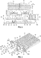
- the FIG. 2 shows a section in three-dimensional representation of the in the FIG. 1
- the pallet strip 15 has two traction means 19A, 19B.
- the illustrated traction means 19A, 19B are sections of two link chains 19A, 19B, the link plates 21 are connected by means of chain pins 22 with each other to two endless link chains 19A, 19B.
- Each two link plates 21 form either narrow chain links 24 or wide chain links 25.
- the chain pins 22 serve not only as hinge points 22, but also as axles 22 for rollers 23. These rollers 23 are arranged laterally of the chain links 24, 25 and run on not shown
- Running rails in the structure 16 of the FIG. 1 shown moving walks 11 are arranged. By the rails, the rollers 23 and thus the traction means 19A, 19B out and supported against gravity, so that the pallet belt 15 does not sag between the two deflection areas 17, 18.
- the chain pins 22 also serve as axles 22 for system rollers 26, which are each arranged between the two link plates 21 of the chain links 24, 25.
- system rollers 26 may for example be made of metal and as in the FIG. 1 shown in the deflection areas 17, 18 via sprockets 27, 28 to be guided, whereby usually made of plastic rollers 23 are spared, since the running surfaces 29 of the system rollers 26 a high surface pressure by the sprockets 27, 28 are exposed.
- a fastening device 30 is respectively arranged between two hinge points 22, which connects the link chain 19 A, 19 B with one of the pallets 14 fixed.
- Each of the fastening devices 30 comprises in the present embodiment, a fastening bolt 31, a cup wheel 32 and a nut 33. So that the pallet 14 is securely connected to the associated chain link 24, 25, the fastening bolt 31 penetrates the two link plates 21 of the chain link 24, 25 and a Cheek 41 of the pallet 14, wherein the bolt head 34 of the fastening bolt 31 projects laterally from the chain link 24, 25.
- FIGS. 4 and 5 At the other end of the fastening bolt 31 is in the FIGS. 4 and 5 more visible thread 35 is present, which receives the nut 33.
- the cup wheel 32 is disposed between the bolt head 34 and the laterally outer link plate 21 of the associated chain link 24, 25.
- the illustrated bolt heads 34 of the mounting bolts 31 appear to have different lengths. In fact, however, all fastening bolts 31 used are identical. The impression of the different length bolt heads 34 is due to the special installation of the cup wheels 32, which in connection with the description of FIGS. 4 and 5 is explained in more detail.
- the pallet 14 is limited in its width by two parallel, in the intended direction of movement X of the pallet 14 extending end faces 42, 43. Between the two end faces 42,43 extends a rectangular tread surface 44.
- the top of the tread surface 44 has a tread pattern in the form of a series of parallel, extending from the front edge 45 to the trailing edge 46 of the tread surface 44 ribs or webs.
- the ribs thus also extend in the intended direction of movement X of the pallet 14. Further, the ribs are dimensioned for engagement in comb structures, not shown, which are arranged in the deflection regions 17, 18 of the moving walk 11.
- At least one shoulder 47 is arranged on each of the two end faces 42, 43.
- the pallets 14 between the two link chains 19A, 19B can be conveniently arranged, since the shoulders 47 of the arranged between the link chains 19A, 19B pallets 14 rest on the chain links 24, 24 and thereby the alignment work of the pallet 14 to the associated chain link 24, 25th is substantially reduced until the fastening bolt 31 by a in the FIG. 5 visible recess or bore of the cheek 41 can be inserted therethrough.
- the attached pallets 14 connect the two hinge chains 19A, 19B thus transversely to the intended direction of movement X with each other.
- the fastening device 30 or the correct fit of the fastening bolts 31 can be monitored by means of at least one monitoring sensor 95 arranged in the moving walk.
- the monitoring sensor 95 is fixedly attached to the supporting structure, not shown, so that in a complete rotation of the pallet strip 15, each fastening device 30 has moved past the monitoring sensor 95.
- the position of one end of the fastening bolt 31, preferably of the bolt head 34 is optically or mechanically scanned.
- the minimum number of monitoring sensors 95 per moving walkway 11 depends on the number of rows of fastening devices 30 and thus on the number of traction means 19A, 19B of a pallet band 15.
- the sensor signal of the monitoring sensor 95 can be compared for example in a monitoring unit 96 with a desired value or desired state.
- the monitoring unit 96 is preferably provided with a moving walk control unit 90 (see FIG. 1 ), so that the pallet band 15 of the moving walk 11 is stopped by the latter when the monitoring unit 96 has determined a loosened fastening device 30.
- the monitoring unit 96 can also be integrated in the moving walk control unit 90.
- FIG. 3 shows in plan view a section of the in the FIG. 2 Due to the top view, the cheek 41 and the shoulder 47 of the pallet 14 can be seen better.
- the cheek 47 rests directly against the link plate 21 of the link chain 19A facing it in the mounted state.
- a spacing element 39 is arranged between the cheek 47 and the link plate 21, so that pallets 14 of identical manufacture are fastened to the narrow chain links 24 and to the wide chain links 25 can.
- the running rail 60 has a guide flank 62 in the movement direction X and thus in the longitudinal extent of the moving walk 11. Since the bolt heads 34 laterally project beyond the rollers 23, they are in contact with the guide flank 62 before the rollers 23 contact the guide flank 62. This can prevent the rollers 23, which are usually made of plastic, from being damaged by the guide flank 62. The occurring sliding friction between the fastening bolt 31 and the guide flank 62 can be minimized if one end of the fastening bolt 31, for example, the bolt head 34 with a Coated coating coated, or as shown, with a sliding member 50 is provided.
- FIG. 4 shows in three-dimensional representation the fixation of the FIG. 3 known pallets 14 and fastening devices 30, on a link chain 69A arranged between the link plates 21 rollers 23. Since this embodiment only in the arrangement of the rollers 23 in the hinge chain 69A of the embodiment of Figures 2 and 3 differs, the same reference numerals are used for the same parts.
- the FIG. 5 also shows the pallet strip 15 from the FIG. 4 with cut hinge chain 69A and cut fasteners 30 in three-dimensional representation.
- the cup wheel has a pot bottom ring 52, which is followed by a peripheral pot rim 51.
- the inner diameter D of the pot rim 51 is greater than the outer diameter K (in the present embodiment, the corner of the hexagonal bolt head 34) of the fitting in the mounted state on Topfêtring 52 portion of the fastening bolt 31.
- the inner height T of the pot rim 51 corresponds to the thickness Z at least one link plate 21st of the chain link 24, 25.
- the inner height T may not be confused with the thickness S of the cup wheel 32.
- the thickness S corresponds to the sum of the inner height T and pot bottom thickness P (see FIG. 5 ).
- Cup wheel 32 are arranged between the bolt head 34 of the mounting bolt 31 and the pallet 14 facing away from the chain link 21 of the chain 69A that at narrow chain links 24 of the pot rim 51 and wide chain links 25 of the bottom pan ring 52 on the link plate 21 of the respective chain link 24, 25th is applied.
- FIG. 4 two further embodiments of a sliding element are also shown.
- the first of these variants has a mushroom-shaped sliding element 53 with a mandrel 54, which mandrel 54 can be pressed into a bore 55 which is arranged on the front side of the bolt head 34.
- the second of these variants comprises a trackball 58, which is, for example, a hard chrome steel ball, and one, for example made of brass ring plug 59. These two parts are so inserted into the bore 55 that the trackball 58 slightly from the ring plug 59 and thus the front side the bolt head 34 protrudes, but is caught by the annular plug 59 in the bore 55. If the trackball 58 now touches a guide edge, it rolls on this and forces the pallet strip 15 along the guide edge to roll.
- the mounted mounting bolt 31 is in a support sleeve 56, 57, which connects the two link plates 21 of a chain link 24, 25 together.
- This support sleeve 56, 57 serves to generate and maintain a preload force within this screw connection or fastening device 30 when tightening the nut 33 on the fastening bolt 31. Without the support sleeve 56, 57, the two link plates 21 would be pulled in the middle against each other and thereby the chain link 24, 25 plastically deformed. Since the link chain 69A has narrow chain links 24 and wide chain links 25, in the present example, the support sleeves 56, 57 must have different lengths. The matching to the narrow chain links 24 support sleeve 56 serves at the same time the attachment of the spacer element 39 on the narrow chain link 24, since it protrudes into the spacer element 39.
- pallets 14 can be attached to articulated chains with three different widths chain links with the inventive fastening device 30, provided that in FIG. 5 characterized Topfêtch P is equal to the thickness Z of a link plate 21.
- a pallet band 15 may also have only one traction means 19A, 19B, 69A, which is preferably arranged centrally with respect to the width of the pallet band 15 of the pallets 14.
- the cup wheel does not necessarily have to be circular. It may, for example, also have a cup bottom ring with a triangular, square, rectangular, polygonal or elliptical base surface, wherein the pot edge does not necessarily have to rotate exactly at the edges of this base surface of the cup bottom ring.
Landscapes
- Engineering & Computer Science (AREA)
- Mechanical Engineering (AREA)
- Escalators And Moving Walkways (AREA)
- Clamps And Clips (AREA)
- Pinball Game Machines (AREA)
- Types And Forms Of Lifts (AREA)
- Connection Of Plates (AREA)
- Pallets (AREA)
- Road Paving Machines (AREA)
Priority Applications (1)
| Application Number | Priority Date | Filing Date | Title |
|---|---|---|---|
| PL15721278T PL3148917T3 (pl) | 2014-05-28 | 2015-05-13 | Urządzenie mocujące do mocowania palety na cięgnie |
Applications Claiming Priority (2)
| Application Number | Priority Date | Filing Date | Title |
|---|---|---|---|
| EP14170277 | 2014-05-28 | ||
| PCT/EP2015/060614 WO2015180964A1 (de) | 2014-05-28 | 2015-05-13 | Befestigungsvorrichtung zum befestigen einer palette an einem zugmittel |
Publications (2)
| Publication Number | Publication Date |
|---|---|
| EP3148917A1 EP3148917A1 (de) | 2017-04-05 |
| EP3148917B1 true EP3148917B1 (de) | 2018-05-02 |
Family
ID=50846822
Family Applications (1)
| Application Number | Title | Priority Date | Filing Date |
|---|---|---|---|
| EP15721278.8A Active EP3148917B1 (de) | 2014-05-28 | 2015-05-13 | Befestigungsvorrichtung zum befestigen einer palette an einem zugmittel |
Country Status (14)
| Country | Link |
|---|---|
| US (1) | US9932206B2 (pl) |
| EP (1) | EP3148917B1 (pl) |
| KR (1) | KR20170013234A (pl) |
| CN (1) | CN106458452B (pl) |
| AR (1) | AR100631A1 (pl) |
| AU (1) | AU2015266277B2 (pl) |
| CA (1) | CA2948078A1 (pl) |
| ES (1) | ES2670682T3 (pl) |
| MX (1) | MX2016015416A (pl) |
| PL (1) | PL3148917T3 (pl) |
| RU (1) | RU2016151169A (pl) |
| TR (1) | TR201810818T4 (pl) |
| TW (1) | TW201545963A (pl) |
| WO (1) | WO2015180964A1 (pl) |
Families Citing this family (7)
| Publication number | Priority date | Publication date | Assignee | Title |
|---|---|---|---|---|
| DE102015122488A1 (de) * | 2015-12-22 | 2017-06-22 | Sig Technology Ag | Vorrichtung zum Transport von Verpackungen |
| EP3231760A1 (en) | 2016-04-15 | 2017-10-18 | Otis Elevator Company | Fixing modules and pallets for a pallet conveyor |
| EP3231761B1 (en) | 2016-04-15 | 2019-02-20 | Otis Elevator Company | Pallet conveyor |
| DE102017004507A1 (de) * | 2017-05-11 | 2018-11-15 | Michael Kollmey | Rolltreppe |
| JP6770011B2 (ja) * | 2018-02-09 | 2020-10-14 | ファナック株式会社 | 千鳥型のコンベアチェーン |
| ES2968825T3 (es) * | 2018-10-30 | 2024-05-14 | Inventio Ag | Procedimiento para montar una cadena transportadora para una cinta de plataformas de un pasillo móvil |
| EP3747822B1 (en) * | 2019-06-03 | 2024-05-01 | Otis Elevator Company | Conveyance element for a conveyor |
Family Cites Families (10)
| Publication number | Priority date | Publication date | Assignee | Title |
|---|---|---|---|---|
| US2059063A (en) | 1935-04-15 | 1936-10-27 | Detroit Steel Casting Company | Conveyer |
| DE1756813A1 (de) * | 1968-07-17 | 1970-09-17 | Landschulze Ernst August | Laufrollen Stufen Ketten-Verbindung von Fahrtreppen |
| US3782533A (en) * | 1972-09-20 | 1974-01-01 | Allis Chalmers | Stabilized side plate construction for grate conveyor |
| CH618394A5 (pl) | 1977-05-25 | 1980-07-31 | Inventio Ag | |
| GB2310185B (en) * | 1996-02-13 | 1999-06-16 | Precision Chains | Chain drive mechanism |
| ATE251582T1 (de) * | 1998-06-16 | 2003-10-15 | Laitram Llc | Modulares band mit konischen, länglichen gelenkbolzen |
| ATE414853T1 (de) * | 2002-01-31 | 2008-12-15 | Frost Links Inc | Verschleissmessvorrichtung |
| JP2003226481A (ja) * | 2002-02-04 | 2003-08-12 | Mitsubishi Electric Corp | マンコンベアの踏板注意標識帯 |
| ES2397840T3 (es) * | 2005-08-04 | 2013-03-11 | Inventio Ag | Escalera mecánica |
| ES2298091B1 (es) * | 2007-10-17 | 2009-06-12 | Thyssenkrupp Elevator (Es/Pbb) Ltd. | Pasillo movil. |
-
2015
- 2015-05-13 KR KR1020167032863A patent/KR20170013234A/ko not_active Withdrawn
- 2015-05-13 PL PL15721278T patent/PL3148917T3/pl unknown
- 2015-05-13 AU AU2015266277A patent/AU2015266277B2/en not_active Ceased
- 2015-05-13 RU RU2016151169A patent/RU2016151169A/ru not_active Application Discontinuation
- 2015-05-13 US US15/314,169 patent/US9932206B2/en active Active
- 2015-05-13 ES ES15721278.8T patent/ES2670682T3/es active Active
- 2015-05-13 TR TR2018/10818T patent/TR201810818T4/tr unknown
- 2015-05-13 MX MX2016015416A patent/MX2016015416A/es unknown
- 2015-05-13 CA CA2948078A patent/CA2948078A1/en not_active Abandoned
- 2015-05-13 EP EP15721278.8A patent/EP3148917B1/de active Active
- 2015-05-13 CN CN201580027512.XA patent/CN106458452B/zh active Active
- 2015-05-13 WO PCT/EP2015/060614 patent/WO2015180964A1/de not_active Ceased
- 2015-05-25 TW TW104116642A patent/TW201545963A/zh unknown
- 2015-05-27 AR ARP150101667A patent/AR100631A1/es unknown
Non-Patent Citations (1)
| Title |
|---|
| None * |
Also Published As
| Publication number | Publication date |
|---|---|
| WO2015180964A1 (de) | 2015-12-03 |
| AU2015266277B2 (en) | 2018-09-27 |
| TW201545963A (zh) | 2015-12-16 |
| US20170197809A1 (en) | 2017-07-13 |
| CN106458452B (zh) | 2019-03-15 |
| MX2016015416A (es) | 2017-02-22 |
| TR201810818T4 (tr) | 2018-08-27 |
| EP3148917A1 (de) | 2017-04-05 |
| CN106458452A (zh) | 2017-02-22 |
| RU2016151169A (ru) | 2018-09-24 |
| CA2948078A1 (en) | 2015-12-03 |
| US9932206B2 (en) | 2018-04-03 |
| KR20170013234A (ko) | 2017-02-06 |
| AR100631A1 (es) | 2016-10-19 |
| AU2015266277A1 (en) | 2016-12-15 |
| PL3148917T3 (pl) | 2018-09-28 |
| ES2670682T3 (es) | 2018-05-31 |
Similar Documents
| Publication | Publication Date | Title |
|---|---|---|
| EP3148917B1 (de) | Befestigungsvorrichtung zum befestigen einer palette an einem zugmittel | |
| EP3060511B1 (de) | Befestigungsvorrichtung zum befestigen einer stufe oder palette an einem zugmittel | |
| EP3099617B1 (de) | Palette für einen fahrsteig oder stufe für eine fahrtreppe | |
| EP1900621B1 (de) | Auswechselbares Verschleißpolster, sowie Verfahren zur Herstellung von Verschleißpolstern für eine Gleiskette | |
| DE60105680T2 (de) | Rolle für Kette und mit der Rolle versehene Kette | |
| EP2900586B1 (de) | Führungsleiste für eine laufschiene einer fahrtreppe oder eines fahrsteiges | |
| EP3044153B1 (de) | Palette für einen fahrsteig oder stufe für eine fahrtreppe | |
| EP2173652B1 (de) | Trittelement für eine fahreinrichtung | |
| EP2636830B1 (de) | Türbandbefestigung, Baugruppe mit der Türbandbefestigung und einem Türband sowie Türanordnung | |
| DE4025706C2 (de) | Plattenförderband | |
| DE112022001583B4 (de) | Kettenglied sowie Laschenkette | |
| EP3464149B1 (de) | Bodenabdeckung einer personenfördereinrichtung | |
| EP3873841B1 (de) | Förderkette für ein palettenband eines fahrsteiges geringer bauhöhe | |
| EP3887301A1 (de) | Verfahren zum montieren einer förderkette für ein palettenband eines fahrsteigs | |
| DE102021106744B4 (de) | Kettenglied sowie Laschenkette und Kettenförderer | |
| WO2000059810A2 (de) | Antriebssystem, insbesondere für förderrollen | |
| EP0869034B1 (de) | Dachreling für Fahrzeuge | |
| EP3368461B1 (de) | Sicherungselement für umlenkeinheit | |
| EP3390264B1 (de) | Bodenabdeckung einer personenfördereinrichtung | |
| DE4216372A1 (de) | Fördervorrichtung für empfindliche Stückgüter, insbesondere keramische Formlinge | |
| EP3056753A2 (de) | Positionieren von hülsensegmenten | |
| EP4538202A1 (de) | Vorrichtung zum befördern von paletten entlang einer förderebene in einer förderrichtung und verfahren zum befördern von paletten mittels der vorrichtung | |
| DE10012958A1 (de) | Vorrichtung zum Abheben von Fördergut, insbesondere Werkstückträgern, von einer Förderbahn | |
| DE102018127824A1 (de) | Transportkette mit unterschiedliche Härtebereiche aufweisenden Transportstiften | |
| DE29603962U1 (de) | Befestigungseinrichtung für die Stufen bzw. Paletten von Rolltreppen bzw. Rollsteigen |
Legal Events
| Date | Code | Title | Description |
|---|---|---|---|
| PUAI | Public reference made under article 153(3) epc to a published international application that has entered the european phase |
Free format text: ORIGINAL CODE: 0009012 |
|
| 17P | Request for examination filed |
Effective date: 20161102 |
|
| AK | Designated contracting states |
Kind code of ref document: A1 Designated state(s): AL AT BE BG CH CY CZ DE DK EE ES FI FR GB GR HR HU IE IS IT LI LT LU LV MC MK MT NL NO PL PT RO RS SE SI SK SM TR |
|
| AX | Request for extension of the european patent |
Extension state: BA ME |
|
| DAV | Request for validation of the european patent (deleted) | ||
| DAX | Request for extension of the european patent (deleted) | ||
| GRAP | Despatch of communication of intention to grant a patent |
Free format text: ORIGINAL CODE: EPIDOSNIGR1 |
|
| INTG | Intention to grant announced |
Effective date: 20171206 |
|
| GRAS | Grant fee paid |
Free format text: ORIGINAL CODE: EPIDOSNIGR3 |
|
| GRAA | (expected) grant |
Free format text: ORIGINAL CODE: 0009210 |
|
| AK | Designated contracting states |
Kind code of ref document: B1 Designated state(s): AL AT BE BG CH CY CZ DE DK EE ES FI FR GB GR HR HU IE IS IT LI LT LU LV MC MK MT NL NO PL PT RO RS SE SI SK SM TR |
|
| REG | Reference to a national code |
Ref country code: GB Ref legal event code: FG4D Free format text: NOT ENGLISH |
|
| REG | Reference to a national code |
Ref country code: CH Ref legal event code: EP Ref country code: AT Ref legal event code: REF Ref document number: 995005 Country of ref document: AT Kind code of ref document: T Effective date: 20180515 |
|
| REG | Reference to a national code |
Ref country code: FR Ref legal event code: PLFP Year of fee payment: 4 |
|
| REG | Reference to a national code |
Ref country code: DE Ref legal event code: R096 Ref document number: 502015004138 Country of ref document: DE Ref country code: IE Ref legal event code: FG4D Free format text: LANGUAGE OF EP DOCUMENT: GERMAN |
|
| REG | Reference to a national code |
Ref country code: ES Ref legal event code: FG2A Ref document number: 2670682 Country of ref document: ES Kind code of ref document: T3 Effective date: 20180531 |
|
| REG | Reference to a national code |
Ref country code: NL Ref legal event code: MP Effective date: 20180502 |
|
| REG | Reference to a national code |
Ref country code: LT Ref legal event code: MG4D |
|
| PG25 | Lapsed in a contracting state [announced via postgrant information from national office to epo] |
Ref country code: SE Free format text: LAPSE BECAUSE OF FAILURE TO SUBMIT A TRANSLATION OF THE DESCRIPTION OR TO PAY THE FEE WITHIN THE PRESCRIBED TIME-LIMIT Effective date: 20180502 Ref country code: FI Free format text: LAPSE BECAUSE OF FAILURE TO SUBMIT A TRANSLATION OF THE DESCRIPTION OR TO PAY THE FEE WITHIN THE PRESCRIBED TIME-LIMIT Effective date: 20180502 Ref country code: NO Free format text: LAPSE BECAUSE OF FAILURE TO SUBMIT A TRANSLATION OF THE DESCRIPTION OR TO PAY THE FEE WITHIN THE PRESCRIBED TIME-LIMIT Effective date: 20180802 Ref country code: BG Free format text: LAPSE BECAUSE OF FAILURE TO SUBMIT A TRANSLATION OF THE DESCRIPTION OR TO PAY THE FEE WITHIN THE PRESCRIBED TIME-LIMIT Effective date: 20180802 Ref country code: LT Free format text: LAPSE BECAUSE OF FAILURE TO SUBMIT A TRANSLATION OF THE DESCRIPTION OR TO PAY THE FEE WITHIN THE PRESCRIBED TIME-LIMIT Effective date: 20180502 |
|
| PG25 | Lapsed in a contracting state [announced via postgrant information from national office to epo] |
Ref country code: GR Free format text: LAPSE BECAUSE OF FAILURE TO SUBMIT A TRANSLATION OF THE DESCRIPTION OR TO PAY THE FEE WITHIN THE PRESCRIBED TIME-LIMIT Effective date: 20180803 Ref country code: HR Free format text: LAPSE BECAUSE OF FAILURE TO SUBMIT A TRANSLATION OF THE DESCRIPTION OR TO PAY THE FEE WITHIN THE PRESCRIBED TIME-LIMIT Effective date: 20180502 Ref country code: LV Free format text: LAPSE BECAUSE OF FAILURE TO SUBMIT A TRANSLATION OF THE DESCRIPTION OR TO PAY THE FEE WITHIN THE PRESCRIBED TIME-LIMIT Effective date: 20180502 Ref country code: NL Free format text: LAPSE BECAUSE OF FAILURE TO SUBMIT A TRANSLATION OF THE DESCRIPTION OR TO PAY THE FEE WITHIN THE PRESCRIBED TIME-LIMIT Effective date: 20180502 Ref country code: RS Free format text: LAPSE BECAUSE OF FAILURE TO SUBMIT A TRANSLATION OF THE DESCRIPTION OR TO PAY THE FEE WITHIN THE PRESCRIBED TIME-LIMIT Effective date: 20180502 |
|
| REG | Reference to a national code |
Ref country code: CH Ref legal event code: PL |
|
| REG | Reference to a national code |
Ref country code: BE Ref legal event code: MM Effective date: 20180531 |
|
| PG25 | Lapsed in a contracting state [announced via postgrant information from national office to epo] |
Ref country code: RO Free format text: LAPSE BECAUSE OF FAILURE TO SUBMIT A TRANSLATION OF THE DESCRIPTION OR TO PAY THE FEE WITHIN THE PRESCRIBED TIME-LIMIT Effective date: 20180502 Ref country code: EE Free format text: LAPSE BECAUSE OF FAILURE TO SUBMIT A TRANSLATION OF THE DESCRIPTION OR TO PAY THE FEE WITHIN THE PRESCRIBED TIME-LIMIT Effective date: 20180502 Ref country code: DK Free format text: LAPSE BECAUSE OF FAILURE TO SUBMIT A TRANSLATION OF THE DESCRIPTION OR TO PAY THE FEE WITHIN THE PRESCRIBED TIME-LIMIT Effective date: 20180502 Ref country code: SK Free format text: LAPSE BECAUSE OF FAILURE TO SUBMIT A TRANSLATION OF THE DESCRIPTION OR TO PAY THE FEE WITHIN THE PRESCRIBED TIME-LIMIT Effective date: 20180502 |
|
| REG | Reference to a national code |
Ref country code: DE Ref legal event code: R097 Ref document number: 502015004138 Country of ref document: DE |
|
| REG | Reference to a national code |
Ref country code: IE Ref legal event code: MM4A |
|
| PG25 | Lapsed in a contracting state [announced via postgrant information from national office to epo] |
Ref country code: CH Free format text: LAPSE BECAUSE OF NON-PAYMENT OF DUE FEES Effective date: 20180531 Ref country code: SM Free format text: LAPSE BECAUSE OF FAILURE TO SUBMIT A TRANSLATION OF THE DESCRIPTION OR TO PAY THE FEE WITHIN THE PRESCRIBED TIME-LIMIT Effective date: 20180502 Ref country code: LI Free format text: LAPSE BECAUSE OF NON-PAYMENT OF DUE FEES Effective date: 20180531 |
|
| PLBE | No opposition filed within time limit |
Free format text: ORIGINAL CODE: 0009261 |
|
| STAA | Information on the status of an ep patent application or granted ep patent |
Free format text: STATUS: NO OPPOSITION FILED WITHIN TIME LIMIT |
|
| PG25 | Lapsed in a contracting state [announced via postgrant information from national office to epo] |
Ref country code: MC Free format text: LAPSE BECAUSE OF FAILURE TO SUBMIT A TRANSLATION OF THE DESCRIPTION OR TO PAY THE FEE WITHIN THE PRESCRIBED TIME-LIMIT Effective date: 20180502 Ref country code: LU Free format text: LAPSE BECAUSE OF NON-PAYMENT OF DUE FEES Effective date: 20180513 |
|
| 26N | No opposition filed |
Effective date: 20190205 |
|
| PG25 | Lapsed in a contracting state [announced via postgrant information from national office to epo] |
Ref country code: IE Free format text: LAPSE BECAUSE OF NON-PAYMENT OF DUE FEES Effective date: 20180513 |
|
| PG25 | Lapsed in a contracting state [announced via postgrant information from national office to epo] |
Ref country code: SI Free format text: LAPSE BECAUSE OF FAILURE TO SUBMIT A TRANSLATION OF THE DESCRIPTION OR TO PAY THE FEE WITHIN THE PRESCRIBED TIME-LIMIT Effective date: 20180502 Ref country code: BE Free format text: LAPSE BECAUSE OF NON-PAYMENT OF DUE FEES Effective date: 20180531 |
|
| PG25 | Lapsed in a contracting state [announced via postgrant information from national office to epo] |
Ref country code: AL Free format text: LAPSE BECAUSE OF FAILURE TO SUBMIT A TRANSLATION OF THE DESCRIPTION OR TO PAY THE FEE WITHIN THE PRESCRIBED TIME-LIMIT Effective date: 20180502 |
|
| GBPC | Gb: european patent ceased through non-payment of renewal fee |
Effective date: 20190513 |
|
| PG25 | Lapsed in a contracting state [announced via postgrant information from national office to epo] |
Ref country code: MT Free format text: LAPSE BECAUSE OF FAILURE TO SUBMIT A TRANSLATION OF THE DESCRIPTION OR TO PAY THE FEE WITHIN THE PRESCRIBED TIME-LIMIT Effective date: 20180502 |
|
| PG25 | Lapsed in a contracting state [announced via postgrant information from national office to epo] |
Ref country code: GB Free format text: LAPSE BECAUSE OF NON-PAYMENT OF DUE FEES Effective date: 20190513 |
|
| PG25 | Lapsed in a contracting state [announced via postgrant information from national office to epo] |
Ref country code: PT Free format text: LAPSE BECAUSE OF FAILURE TO SUBMIT A TRANSLATION OF THE DESCRIPTION OR TO PAY THE FEE WITHIN THE PRESCRIBED TIME-LIMIT Effective date: 20180502 |
|
| PG25 | Lapsed in a contracting state [announced via postgrant information from national office to epo] |
Ref country code: CY Free format text: LAPSE BECAUSE OF FAILURE TO SUBMIT A TRANSLATION OF THE DESCRIPTION OR TO PAY THE FEE WITHIN THE PRESCRIBED TIME-LIMIT Effective date: 20180502 Ref country code: HU Free format text: LAPSE BECAUSE OF FAILURE TO SUBMIT A TRANSLATION OF THE DESCRIPTION OR TO PAY THE FEE WITHIN THE PRESCRIBED TIME-LIMIT; INVALID AB INITIO Effective date: 20150513 Ref country code: MK Free format text: LAPSE BECAUSE OF NON-PAYMENT OF DUE FEES Effective date: 20180502 |
|
| PG25 | Lapsed in a contracting state [announced via postgrant information from national office to epo] |
Ref country code: IS Free format text: LAPSE BECAUSE OF FAILURE TO SUBMIT A TRANSLATION OF THE DESCRIPTION OR TO PAY THE FEE WITHIN THE PRESCRIBED TIME-LIMIT Effective date: 20180902 |
|
| REG | Reference to a national code |
Ref country code: AT Ref legal event code: MM01 Ref document number: 995005 Country of ref document: AT Kind code of ref document: T Effective date: 20200513 |
|
| PGFP | Annual fee paid to national office [announced via postgrant information from national office to epo] |
Ref country code: FR Payment date: 20210526 Year of fee payment: 7 Ref country code: IT Payment date: 20210520 Year of fee payment: 7 |
|
| PG25 | Lapsed in a contracting state [announced via postgrant information from national office to epo] |
Ref country code: AT Free format text: LAPSE BECAUSE OF NON-PAYMENT OF DUE FEES Effective date: 20200513 |
|
| PGFP | Annual fee paid to national office [announced via postgrant information from national office to epo] |
Ref country code: ES Payment date: 20220613 Year of fee payment: 8 |
|
| PG25 | Lapsed in a contracting state [announced via postgrant information from national office to epo] |
Ref country code: FR Free format text: LAPSE BECAUSE OF NON-PAYMENT OF DUE FEES Effective date: 20220531 |
|
| PG25 | Lapsed in a contracting state [announced via postgrant information from national office to epo] |
Ref country code: IT Free format text: LAPSE BECAUSE OF NON-PAYMENT OF DUE FEES Effective date: 20220513 |
|
| PGFP | Annual fee paid to national office [announced via postgrant information from national office to epo] |
Ref country code: CZ Payment date: 20230511 Year of fee payment: 9 |
|
| PGFP | Annual fee paid to national office [announced via postgrant information from national office to epo] |
Ref country code: TR Payment date: 20230503 Year of fee payment: 9 Ref country code: PL Payment date: 20230508 Year of fee payment: 9 |
|
| REG | Reference to a national code |
Ref country code: ES Ref legal event code: FD2A Effective date: 20240628 |
|
| PG25 | Lapsed in a contracting state [announced via postgrant information from national office to epo] |
Ref country code: ES Free format text: LAPSE BECAUSE OF NON-PAYMENT OF DUE FEES Effective date: 20230514 |
|
| PG25 | Lapsed in a contracting state [announced via postgrant information from national office to epo] |
Ref country code: ES Free format text: LAPSE BECAUSE OF NON-PAYMENT OF DUE FEES Effective date: 20230514 |
|
| PG25 | Lapsed in a contracting state [announced via postgrant information from national office to epo] |
Ref country code: CZ Free format text: LAPSE BECAUSE OF NON-PAYMENT OF DUE FEES Effective date: 20240513 |
|
| PG25 | Lapsed in a contracting state [announced via postgrant information from national office to epo] |
Ref country code: CZ Free format text: LAPSE BECAUSE OF NON-PAYMENT OF DUE FEES Effective date: 20240513 |
|
| PG25 | Lapsed in a contracting state [announced via postgrant information from national office to epo] |
Ref country code: PL Free format text: LAPSE BECAUSE OF NON-PAYMENT OF DUE FEES Effective date: 20240513 |
|
| PGFP | Annual fee paid to national office [announced via postgrant information from national office to epo] |
Ref country code: DE Payment date: 20250528 Year of fee payment: 11 |