EP3148917B1 - Fixing device for fixing a pallet to a means of traction - Google Patents
Fixing device for fixing a pallet to a means of traction Download PDFInfo
- Publication number
- EP3148917B1 EP3148917B1 EP15721278.8A EP15721278A EP3148917B1 EP 3148917 B1 EP3148917 B1 EP 3148917B1 EP 15721278 A EP15721278 A EP 15721278A EP 3148917 B1 EP3148917 B1 EP 3148917B1
- Authority
- EP
- European Patent Office
- Prior art keywords
- chain
- link
- chain link
- cup
- plate belt
- Prior art date
- Legal status (The legal status is an assumption and is not a legal conclusion. Google has not performed a legal analysis and makes no representation as to the accuracy of the status listed.)
- Active
Links
Images

Classifications
-
- B—PERFORMING OPERATIONS; TRANSPORTING
- B65—CONVEYING; PACKING; STORING; HANDLING THIN OR FILAMENTARY MATERIAL
- B65G—TRANSPORT OR STORAGE DEVICES, e.g. CONVEYORS FOR LOADING OR TIPPING, SHOP CONVEYOR SYSTEMS OR PNEUMATIC TUBE CONVEYORS
- B65G17/00—Conveyors having an endless traction element, e.g. a chain, transmitting movement to a continuous or substantially-continuous load-carrying surface or to a series of individual load-carriers; Endless-chain conveyors in which the chains form the load-carrying surface
- B65G17/06—Conveyors having an endless traction element, e.g. a chain, transmitting movement to a continuous or substantially-continuous load-carrying surface or to a series of individual load-carriers; Endless-chain conveyors in which the chains form the load-carrying surface having a load-carrying surface formed by a series of interconnected, e.g. longitudinal, links, plates, or platforms
- B65G17/067—Conveyors having an endless traction element, e.g. a chain, transmitting movement to a continuous or substantially-continuous load-carrying surface or to a series of individual load-carriers; Endless-chain conveyors in which the chains form the load-carrying surface having a load-carrying surface formed by a series of interconnected, e.g. longitudinal, links, plates, or platforms the load carrying surface being formed by plates or platforms attached to more than one traction element
-
- B—PERFORMING OPERATIONS; TRANSPORTING
- B65—CONVEYING; PACKING; STORING; HANDLING THIN OR FILAMENTARY MATERIAL
- B65G—TRANSPORT OR STORAGE DEVICES, e.g. CONVEYORS FOR LOADING OR TIPPING, SHOP CONVEYOR SYSTEMS OR PNEUMATIC TUBE CONVEYORS
- B65G39/00—Rollers, e.g. drive rollers, or arrangements thereof incorporated in roller-ways or other types of mechanical conveyors
- B65G39/10—Arrangements of rollers
- B65G39/20—Arrangements of rollers attached to moving belts or chains
-
- B—PERFORMING OPERATIONS; TRANSPORTING
- B66—HOISTING; LIFTING; HAULING
- B66B—ELEVATORS; ESCALATORS OR MOVING WALKWAYS
- B66B23/00—Component parts of escalators or moving walkways
- B66B23/08—Carrying surfaces
- B66B23/10—Carrying belts
-
- B—PERFORMING OPERATIONS; TRANSPORTING
- B66—HOISTING; LIFTING; HAULING
- B66B—ELEVATORS; ESCALATORS OR MOVING WALKWAYS
- B66B23/00—Component parts of escalators or moving walkways
- B66B23/14—Guiding means for carrying surfaces
-
- B—PERFORMING OPERATIONS; TRANSPORTING
- B66—HOISTING; LIFTING; HAULING
- B66B—ELEVATORS; ESCALATORS OR MOVING WALKWAYS
- B66B23/00—Component parts of escalators or moving walkways
- B66B23/14—Guiding means for carrying surfaces
- B66B23/145—Roller assemblies
-
- B—PERFORMING OPERATIONS; TRANSPORTING
- B66—HOISTING; LIFTING; HAULING
- B66B—ELEVATORS; ESCALATORS OR MOVING WALKWAYS
- B66B29/00—Safety devices of escalators or moving walkways
- B66B29/005—Applications of security monitors
Definitions
- the invention relates to a fastening device for connecting a pallet of a moving walkway with a link chain serving as a traction means.
- Moving walkways are well-known and efficient means of transporting people. They are typically used for transporting persons in the horizontal direction, but also in the vertical direction with a slight incline of up to 12 °, for example when carrying users with shopping carts from one floor of a building to another floor. The length and width of the moving walk are selected depending on the expected passenger traffic for each application.
- Pallets are designed as one-piece or multi-part components and their parts usually produced by casting, extrusion, forging and the like.
- Several pallets are usually connected by means of two traction means to a pallet band of a moving walk.
- these traction devices are articulated chains.
- a moving walkway usually has a supporting structure or truss with two deflection areas, between which the pallet belt is guided circumferentially.
- connection between the articulated chain and the pallet must be secure and durable, since disengaging the connection and thus the pallet from the pallet band during operation of the moving walkway can have catastrophic consequences for the users.
- Object of the present invention is therefore to provide a fastening device for connecting a pallet with serving as a traction means hinge chains, which is easy to install, inexpensive to manufacture and in the assembled state or in operation in a simple manner verifiable.
- a pallet strip of a moving walk with pallets arranged one behind the other in the direction of movement, which are arranged between two mutually parallel, formed of different widths chain links link chains.
- Each chain link is connected to one of the pallets by means of at least one fastening device.
- the fastening device has a fastening bolt and a cup wheel, wherein the cup wheel includes a cup bottom ring and a cup rim surrounding the cup bottom ring or pot collar.
- the inner height of the pot edge corresponds to the thickness of at least one link plate of the chain link.
- the inner diameter of the pot edge is greater than the outer diameter of the fitting in the mounted state on the pot bottom ring portion of the fastening bolt.
- the cup wheel with its tuned to the thickness of the link plate inner height and with its matched to the mounting bolt inner diameter allows the same fastening device between narrow and wide links of the articulated chain and the pallets to be attached can be used. Furthermore, the use of the cup wheel also causes all parts of the fastening device remain visible and all bolt ends of the fastening bolts of a pallet strip protrude the same distance from the joints between the articulated chain and pallets. This feature allows a very reliable and easy visual inspection of all fasteners one pallet band, since neither the cup wheel nor the end of the mounting bolt are completely hidden by areas of the articulated chain and / or the pallet. As soon as the bolt end of a fastening bolt projects beyond the other bolt ends of the pallet band, this is immediately recognizable. Of course, the verification of the bolt ends can also be done by means of sensors, wherein per bolt end row of a pallet belt only one sensor is required.
- the verification of the bolt ends is particularly simple if they from the side facing away from the pallets of the articulated chain reluctance their chain plate protrude. To achieve this, penetrates preferably in the mounted state of the fastening bolt at least two mutually parallel link plates of the chain link to be connected to the chain link.
- the cup wheel can be arranged between the bolt head of the fastening bolt and the pallet facing away from the chain link chain, that in narrow chain links the pot edge and wide chain links the Pot bottom ring rests against the link plate of each chain link.
- the link chains only narrow and wide chain links, which are arranged alternately below each other and connected to each other in the joints of the joint chain. If the cup wheels are arranged alternately on the articulated chain, that rests with narrow chain links the pot edge and wide chain links of the bottom ring pot on the link plate of each chain link, all bolt heads protrude equally neglecting the axial play of the joint chain out of the articulated chain.
- the pallet can be most easily attached directly to the articulated chain, when the fastening bolt penetrates a link facing the chain link of the pallet attached to this chain link or protrudes into a bore of the attached to this chain link pallet.
- the bore may for example be a through hole, a blind hole or a threaded blind hole.
- Other options include trained on the cheek grooves, slots, openings, openings and the like, so that the mounting bolt can penetrate the cheek.
- a spacer element can be arranged, the thickness of which corresponds to the thickness of a link plate.
- a thread may be formed, which is screwed into the above-mentioned threaded blind hole or, when the fastening bolt penetrates the cheek of the pallet, for example, receives a nut.
- the best assurance of detachable screw connections can be achieved so that the greatest possible elongation within the screw is available.
- Particularly advantageous in this case are the chain straps of a chain link penetrating fastening bolts. In these, the entire shaft length of the fastening bolt, which is present between the two outer link plates of a chain link, can be exploited as Dehnmother. But so that the chain links are not compressed laterally when tightening the fastening bolt, at least one support sleeve can be arranged between the two outer link plates of the respective chain link, through the bore of the fastening bolt can be pushed.
- each of the link chains may have rollers. These are preferably arranged in the region of the hinge points on the traction means. This has the advantage that the connecting bolts of the articulated chain used in the joints serve at the same time as roller axles.
- the rollers can be arranged between the link plates in the joints of the joint chain.
- each of the hinge chains may also have rollers which are arranged on the side facing away from the pallets outside of the chain links and thus the pallet band in the hinge points.
- damaged rollers can be replaced with new rollers on existing systems without having to remove the articulated chain, as is required in articulated chains with arranged between the chain links rollers.
- the fastening bolts preferably project laterally beyond the rollers.
- the fastening bolts projecting in the lateral direction out of the articulated chain, or extending orthogonally to the conveying direction of the pallet band, can additionally be used. Since the bolt ends (bolt heads and the bolt heads opposite bolt ends) of the fastening bolts are all in line with respect to the conveying direction, the fastening bolts can also be used as guide elements. There are various options for this. For example, a low sliding friction coefficient slider may be disposed at a bolt end of at least one fastening bolt. Of course, the bolt ends may also be coated, for example with a bonded coating or with a plastic coating. Another possibility would be to let in the bolt head a frontally outstanding trackball.
- the above-described pallet band can be used with the inventive fastening device not only in new moving walks.
- an existing moving walk can be modernized by replacing the existing pallet band with a pallet band according to the invention.
- At least one monitoring sensor can also be present, by means of which the position of one end of the fastening bolt relative to the position of a link plate of the associated chain link and relative to the ends of the other fastening bolts can be detected.
- both a defective fastening device, as well as the straight running of the pallet band can be detected simultaneously.
- the position of the ends can be scanned optically and / or mechanically, for example.
- monitoring sensors all possible detection devices such as CCD cameras, TOF cameras, photoelectric sensors, push button, laser scanning, inductive proximity switches and the like can be used more.
- the number of monitoring sensors preferably depends on the number of rows of fastening devices and thus on the number of traction means of a pallet band.
- the sensor signal of the monitoring sensor can be compared in a monitoring unit with a desired value or desired state.
- the monitoring unit then provides information, for example, to the moving walk control or to the safety circuit of the moving walk, whether the pallet band is allowed to circulate, or braked, or even blocked, in order to prevent accidents.
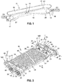
- FIG. 1 schematically shows in side view a moving walkway 11, which connects a first floor E1 with a second floor E2.
- the moving walk 11 could also connect two places on the same level, as is often the case in long corridors of airports.
- the moving walk 11 has a supporting structure 16 or truss 16 with two deflection areas 17, 18. In the deflection areas sprockets 27, 28 are arranged, between which a pallet belt 15 is guided circumferentially.
- the pallet band 15 has traction means 19, on which pallets 14 are arranged.
- a handrail 13 is arranged on a balustrade 12.
- the balustrade 12 is connected at the lower end by means of a Balustradensockels 20 to the supporting structure 16.
- the drive, not shown, of the pallet conveyor 15 is controlled by means of a moving walk control unit 90.
- a monitoring unit 96 is arranged, which with the in the FIG. 2 shown monitoring sensors 95 is connected.
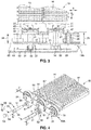
- the FIG. 2 shows a section in three-dimensional representation of the in the FIG. 1
- the pallet strip 15 has two traction means 19A, 19B.
- the illustrated traction means 19A, 19B are sections of two link chains 19A, 19B, the link plates 21 are connected by means of chain pins 22 with each other to two endless link chains 19A, 19B.
- Each two link plates 21 form either narrow chain links 24 or wide chain links 25.
- the chain pins 22 serve not only as hinge points 22, but also as axles 22 for rollers 23. These rollers 23 are arranged laterally of the chain links 24, 25 and run on not shown
- Running rails in the structure 16 of the FIG. 1 shown moving walks 11 are arranged. By the rails, the rollers 23 and thus the traction means 19A, 19B out and supported against gravity, so that the pallet belt 15 does not sag between the two deflection areas 17, 18.
- the chain pins 22 also serve as axles 22 for system rollers 26, which are each arranged between the two link plates 21 of the chain links 24, 25.
- system rollers 26 may for example be made of metal and as in the FIG. 1 shown in the deflection areas 17, 18 via sprockets 27, 28 to be guided, whereby usually made of plastic rollers 23 are spared, since the running surfaces 29 of the system rollers 26 a high surface pressure by the sprockets 27, 28 are exposed.
- a fastening device 30 is respectively arranged between two hinge points 22, which connects the link chain 19 A, 19 B with one of the pallets 14 fixed.
- Each of the fastening devices 30 comprises in the present embodiment, a fastening bolt 31, a cup wheel 32 and a nut 33. So that the pallet 14 is securely connected to the associated chain link 24, 25, the fastening bolt 31 penetrates the two link plates 21 of the chain link 24, 25 and a Cheek 41 of the pallet 14, wherein the bolt head 34 of the fastening bolt 31 projects laterally from the chain link 24, 25.
- FIGS. 4 and 5 At the other end of the fastening bolt 31 is in the FIGS. 4 and 5 more visible thread 35 is present, which receives the nut 33.
- the cup wheel 32 is disposed between the bolt head 34 and the laterally outer link plate 21 of the associated chain link 24, 25.
- the illustrated bolt heads 34 of the mounting bolts 31 appear to have different lengths. In fact, however, all fastening bolts 31 used are identical. The impression of the different length bolt heads 34 is due to the special installation of the cup wheels 32, which in connection with the description of FIGS. 4 and 5 is explained in more detail.
- the pallet 14 is limited in its width by two parallel, in the intended direction of movement X of the pallet 14 extending end faces 42, 43. Between the two end faces 42,43 extends a rectangular tread surface 44.
- the top of the tread surface 44 has a tread pattern in the form of a series of parallel, extending from the front edge 45 to the trailing edge 46 of the tread surface 44 ribs or webs.
- the ribs thus also extend in the intended direction of movement X of the pallet 14. Further, the ribs are dimensioned for engagement in comb structures, not shown, which are arranged in the deflection regions 17, 18 of the moving walk 11.
- At least one shoulder 47 is arranged on each of the two end faces 42, 43.
- the pallets 14 between the two link chains 19A, 19B can be conveniently arranged, since the shoulders 47 of the arranged between the link chains 19A, 19B pallets 14 rest on the chain links 24, 24 and thereby the alignment work of the pallet 14 to the associated chain link 24, 25th is substantially reduced until the fastening bolt 31 by a in the FIG. 5 visible recess or bore of the cheek 41 can be inserted therethrough.
- the attached pallets 14 connect the two hinge chains 19A, 19B thus transversely to the intended direction of movement X with each other.
- the fastening device 30 or the correct fit of the fastening bolts 31 can be monitored by means of at least one monitoring sensor 95 arranged in the moving walk.
- the monitoring sensor 95 is fixedly attached to the supporting structure, not shown, so that in a complete rotation of the pallet strip 15, each fastening device 30 has moved past the monitoring sensor 95.
- the position of one end of the fastening bolt 31, preferably of the bolt head 34 is optically or mechanically scanned.
- the minimum number of monitoring sensors 95 per moving walkway 11 depends on the number of rows of fastening devices 30 and thus on the number of traction means 19A, 19B of a pallet band 15.
- the sensor signal of the monitoring sensor 95 can be compared for example in a monitoring unit 96 with a desired value or desired state.
- the monitoring unit 96 is preferably provided with a moving walk control unit 90 (see FIG. 1 ), so that the pallet band 15 of the moving walk 11 is stopped by the latter when the monitoring unit 96 has determined a loosened fastening device 30.
- the monitoring unit 96 can also be integrated in the moving walk control unit 90.
- FIG. 3 shows in plan view a section of the in the FIG. 2 Due to the top view, the cheek 41 and the shoulder 47 of the pallet 14 can be seen better.
- the cheek 47 rests directly against the link plate 21 of the link chain 19A facing it in the mounted state.
- a spacing element 39 is arranged between the cheek 47 and the link plate 21, so that pallets 14 of identical manufacture are fastened to the narrow chain links 24 and to the wide chain links 25 can.
- the running rail 60 has a guide flank 62 in the movement direction X and thus in the longitudinal extent of the moving walk 11. Since the bolt heads 34 laterally project beyond the rollers 23, they are in contact with the guide flank 62 before the rollers 23 contact the guide flank 62. This can prevent the rollers 23, which are usually made of plastic, from being damaged by the guide flank 62. The occurring sliding friction between the fastening bolt 31 and the guide flank 62 can be minimized if one end of the fastening bolt 31, for example, the bolt head 34 with a Coated coating coated, or as shown, with a sliding member 50 is provided.
- FIG. 4 shows in three-dimensional representation the fixation of the FIG. 3 known pallets 14 and fastening devices 30, on a link chain 69A arranged between the link plates 21 rollers 23. Since this embodiment only in the arrangement of the rollers 23 in the hinge chain 69A of the embodiment of Figures 2 and 3 differs, the same reference numerals are used for the same parts.
- the FIG. 5 also shows the pallet strip 15 from the FIG. 4 with cut hinge chain 69A and cut fasteners 30 in three-dimensional representation.
- the cup wheel has a pot bottom ring 52, which is followed by a peripheral pot rim 51.
- the inner diameter D of the pot rim 51 is greater than the outer diameter K (in the present embodiment, the corner of the hexagonal bolt head 34) of the fitting in the mounted state on Topfêtring 52 portion of the fastening bolt 31.
- the inner height T of the pot rim 51 corresponds to the thickness Z at least one link plate 21st of the chain link 24, 25.
- the inner height T may not be confused with the thickness S of the cup wheel 32.
- the thickness S corresponds to the sum of the inner height T and pot bottom thickness P (see FIG. 5 ).
- Cup wheel 32 are arranged between the bolt head 34 of the mounting bolt 31 and the pallet 14 facing away from the chain link 21 of the chain 69A that at narrow chain links 24 of the pot rim 51 and wide chain links 25 of the bottom pan ring 52 on the link plate 21 of the respective chain link 24, 25th is applied.
- FIG. 4 two further embodiments of a sliding element are also shown.
- the first of these variants has a mushroom-shaped sliding element 53 with a mandrel 54, which mandrel 54 can be pressed into a bore 55 which is arranged on the front side of the bolt head 34.
- the second of these variants comprises a trackball 58, which is, for example, a hard chrome steel ball, and one, for example made of brass ring plug 59. These two parts are so inserted into the bore 55 that the trackball 58 slightly from the ring plug 59 and thus the front side the bolt head 34 protrudes, but is caught by the annular plug 59 in the bore 55. If the trackball 58 now touches a guide edge, it rolls on this and forces the pallet strip 15 along the guide edge to roll.
- the mounted mounting bolt 31 is in a support sleeve 56, 57, which connects the two link plates 21 of a chain link 24, 25 together.
- This support sleeve 56, 57 serves to generate and maintain a preload force within this screw connection or fastening device 30 when tightening the nut 33 on the fastening bolt 31. Without the support sleeve 56, 57, the two link plates 21 would be pulled in the middle against each other and thereby the chain link 24, 25 plastically deformed. Since the link chain 69A has narrow chain links 24 and wide chain links 25, in the present example, the support sleeves 56, 57 must have different lengths. The matching to the narrow chain links 24 support sleeve 56 serves at the same time the attachment of the spacer element 39 on the narrow chain link 24, since it protrudes into the spacer element 39.
- pallets 14 can be attached to articulated chains with three different widths chain links with the inventive fastening device 30, provided that in FIG. 5 characterized Topfêtch P is equal to the thickness Z of a link plate 21.
- a pallet band 15 may also have only one traction means 19A, 19B, 69A, which is preferably arranged centrally with respect to the width of the pallet band 15 of the pallets 14.
- the cup wheel does not necessarily have to be circular. It may, for example, also have a cup bottom ring with a triangular, square, rectangular, polygonal or elliptical base surface, wherein the pot edge does not necessarily have to rotate exactly at the edges of this base surface of the cup bottom ring.
Landscapes
- Engineering & Computer Science (AREA)
- Mechanical Engineering (AREA)
- Escalators And Moving Walkways (AREA)
- Clamps And Clips (AREA)
- Pinball Game Machines (AREA)
- Types And Forms Of Lifts (AREA)
- Pallets (AREA)
- Road Paving Machines (AREA)
- Connection Of Plates (AREA)
Description
Die Erfindung betrifft eine Befestigungsvorrichtung zum Verbinden einer Palette eines Fahrsteiges mit einer als Zugmittel dienenden Gelenkkette.The invention relates to a fastening device for connecting a pallet of a moving walkway with a link chain serving as a traction means.
Fahrsteige sind allgemein bekannte und effiziente Einrichtungen zum Transportieren von Personen. Sie werden typischerweise zum Transport von Personen in horizontaler Richtung, aber auch in vertikaler Richtung mit leichter Steigung bis zu 12° verwendet, wenn sie beispielsweise von einem Stockwerk eines Gebäudes zu einem anderen Stockwerk Benutzer mit Einkaufswagen befördern soll. Die Länge und die Breite des Fahrsteiges werden in Abhängigkeit vom erwarteten Passagierverkehr bei der jeweiligen Anwendung ausgewählt.Moving walkways are well-known and efficient means of transporting people. They are typically used for transporting persons in the horizontal direction, but also in the vertical direction with a slight incline of up to 12 °, for example when carrying users with shopping carts from one floor of a building to another floor. The length and width of the moving walk are selected depending on the expected passenger traffic for each application.
Paletten werden als einstückige oder mehrteilige Bauteile konzipiert und deren Teile in der Regel durch Gußverfahren, Strangpreßverfahren, Schmiedeverfahren und dergleichen mehr hergestellt. Mehrere Paletten werden üblicherweise mittels zweier Zugmittel zu einem Palettenband eines Fahrsteiges verbunden. In der Regel sind diese Zugmittel Gelenkketten. Ein Fahrsteig weist meistens ein Tragwerk beziehungsweise Fachwerk mit zwei Umlenkbereichen auf, zwischen denen das Palettenband umlaufend geführt ist.Pallets are designed as one-piece or multi-part components and their parts usually produced by casting, extrusion, forging and the like. Several pallets are usually connected by means of two traction means to a pallet band of a moving walk. As a rule, these traction devices are articulated chains. A moving walkway usually has a supporting structure or truss with two deflection areas, between which the pallet belt is guided circumferentially.
Die Verbindung zwischen der Gelenkkette und der Palette muss sicher und dauerhaft sein, da ein Lösen der Verbindung und damit der Palette vom Palettenband während des Betriebes des Fahrsteiges katastrophale Folgen für die Benutzer haben kann.The connection between the articulated chain and the pallet must be secure and durable, since disengaging the connection and thus the pallet from the pallet band during operation of the moving walkway can have catastrophic consequences for the users.
In der
Aufgabe der vorliegenden Erfindung ist daher, eine Befestigungsvorrichtung zum Verbinden einer Palette mit einer als Zugmittel dienenden Gelenkketten zu schaffen, welche einfach montierbar, kostengünstig herstellbar und in montiertem Zustand beziehungsweise im Betrieb auf einfache Weise überprüfbar ist.Object of the present invention is therefore to provide a fastening device for connecting a pallet with serving as a traction means hinge chains, which is easy to install, inexpensive to manufacture and in the assembled state or in operation in a simple manner verifiable.
Diese Aufgabe wird gelöst durch ein Palettenband eines Fahrsteiges mit in Bewegungsrichtung hintereinander angeordneten Paletten, die zwischen zwei zueinander parallel verlaufenden, aus unterschiedlich breiten Kettengliedern gebildeten Gelenkketten angeordnet sind. Jedes Kettenglied ist mittels mindestens einer Befestigungsvorrichtung mit einer der Paletten verbunden. Die Befestigungsvorrichtung weist einen Befestigungsbolzen und eine Topfscheibe auf, wobei die Topfscheibe einen Topfbodenring und einen den Topfbodenring umlaufenden Topfrand beziehungsweise Topfkragen beinhaltet. Die Innenhöhe des Topfrandes entspricht der Dicke zumindest einer Kettenlasche des Kettengliedes. Zudem ist der Innendurchmesser des Topfrandes grösser als der Außendurchmesser des in montiertem Zustand am Topfbodenring anliegenden Bereichs des Befestigungsbolzens.This object is achieved by a pallet strip of a moving walk with pallets arranged one behind the other in the direction of movement, which are arranged between two mutually parallel, formed of different widths chain links link chains. Each chain link is connected to one of the pallets by means of at least one fastening device. The fastening device has a fastening bolt and a cup wheel, wherein the cup wheel includes a cup bottom ring and a cup rim surrounding the cup bottom ring or pot collar. The inner height of the pot edge corresponds to the thickness of at least one link plate of the chain link. In addition, the inner diameter of the pot edge is greater than the outer diameter of the fitting in the mounted state on the pot bottom ring portion of the fastening bolt.
Die Topfscheibe mit ihrer auf die Dicke der Kettenlasche abgestimmten Innenhöhe und mit ihrem auf den Befestigungsbolzen abgestimmten Innendurchmesser ermöglicht, dass dieselbe Befestigungsvorrichtung zwischen schmalen und breiten Kettengliedern der Gelenkkette und der daran zu befestigenden Paletten eingesetzt werden kann. Ferner führt die Verwendung der Topfscheibe auch dazu, dass alle Teile der Befestigungsvorrichtung sichtbar bleiben und alle Bolzenenden der Befestigungsbolzen eines Palettenbandes gleich weit aus den Verbindungsstellen zwischen Gelenkkette und Paletten herausragen. Diese Eigenschaft ermöglicht eine äußerst zuverlässige und einfache visuelle Überprüfung aller Befestigungsvorrichtungen eins Palettenbandes, da weder die Topfscheibe noch das Ende des Befestigungsbolzens durch Bereiche der Gelenkkette und/oder der Palette vollständig verborgen werden. Sobald das Bolzenende eines Befestigungsbolzens über die anderen Bolzenenden des Palettenbandes hinausragt, ist dies sofort erkennbar. Selbstverständlich kann die Überprüfung der Bolzenenden auch mittels Sensoren erfolgen, wobei pro Bolzenenden-Reihe eines Palettenbandes nur ein Sensor erforderlich ist.The cup wheel with its tuned to the thickness of the link plate inner height and with its matched to the mounting bolt inner diameter allows the same fastening device between narrow and wide links of the articulated chain and the pallets to be attached can be used. Furthermore, the use of the cup wheel also causes all parts of the fastening device remain visible and all bolt ends of the fastening bolts of a pallet strip protrude the same distance from the joints between the articulated chain and pallets. This feature allows a very reliable and easy visual inspection of all fasteners one pallet band, since neither the cup wheel nor the end of the mounting bolt are completely hidden by areas of the articulated chain and / or the pallet. As soon as the bolt end of a fastening bolt projects beyond the other bolt ends of the pallet band, this is immediately recognizable. Of course, the verification of the bolt ends can also be done by means of sensors, wherein per bolt end row of a pallet belt only one sensor is required.
Die Überprüfung der Bolzenenden ist besonders einfach, wenn diese aus der den Paletten abgewandten Seite der Gelenkkette beziehungswese deren Kettenlasche herausragen. Um dies zu erreichen, durchdringt vorzugsweise in montiertem Zustand der Befestigungsbolzen zumindest zwei parallel zueinander angeordnete Kettenlaschen des mit der Palette zu verbindenden Kettengliedes.The verification of the bolt ends is particularly simple if they from the side facing away from the pallets of the articulated chain reluctance their chain plate protrude. To achieve this, penetrates preferably in the mounted state of the fastening bolt at least two mutually parallel link plates of the chain link to be connected to the chain link.
Da eine Gelenkketten konstruktionsbedingt zumindest zwei unterschiedliche Gruppen von Kettengliedern aufweist die sich primär in ihrer Breite unterscheiden, kann die Topfscheibe derart zwischen dem Bolzenkopf des Befestigungsbolzens und der der Palette abgewandten Kettenlasche der Gelenkkette angeordnet werden, dass bei schmalen Kettengliedern der Topfrand und bei breiten Kettengliedern der Topfbodenring an der Kettenlasche des jeweiligen Kettengliedes anliegt.Since a joint chains by design has at least two different groups of chain links which differ primarily in their width, the cup wheel can be arranged between the bolt head of the fastening bolt and the pallet facing away from the chain link chain, that in narrow chain links the pot edge and wide chain links the Pot bottom ring rests against the link plate of each chain link.
Üblicherweise weisen die Gelenkketten nur schmale und breite Kettenglieder auf, die alternierend einander nachfolgend angeordnet und in den Gelenkstellen der Gelenkkette miteinander verbunden sind. Wenn die Topfscheiben derart an der Gelenkkette alternieren angeordnet sind, dass bei schmalen Kettengliedern der Topfrand und bei breiten Kettengliedern der Topfbodenring an der Kettenlasche des jeweiligen Kettengliedes anliegt, ragen alle Bolzenköpfe unter der Vernachlässigung des Axialspiels der Gelenkkette gleich weit aus der Gelenkkette heraus.Usually, the link chains only narrow and wide chain links, which are arranged alternately below each other and connected to each other in the joints of the joint chain. If the cup wheels are arranged alternately on the articulated chain, that rests with narrow chain links the pot edge and wide chain links of the bottom ring pot on the link plate of each chain link, all bolt heads protrude equally neglecting the axial play of the joint chain out of the articulated chain.
Die Palette lässt sich am einfachsten direkt an der Gelenkkette befestigen, wenn der Befestigungsbolzen eine dem Kettenglied zugewandte Wange der an diesem Kettenglied befestigten Palette durchdringt oder in eine Bohrung der an diesem Kettenglied befestigten Palette hineinragt. Die Bohrung kann beispielsweise eine Durchgangsbohrung, eine Sacklochbohrung oder eine Gewinde-Sacklochbohrung sein. Weitere Möglichkeiten sind an der Wange ausgebildete Nuten, Schlitze, Öffnungen, Durchbrüche und dergleichen mehr, damit der Befestigungsbolzen die Wange durchdringen kann.The pallet can be most easily attached directly to the articulated chain, when the fastening bolt penetrates a link facing the chain link of the pallet attached to this chain link or protrudes into a bore of the attached to this chain link pallet. The bore may for example be a through hole, a blind hole or a threaded blind hole. Other options include trained on the cheek grooves, slots, openings, openings and the like, so that the mounting bolt can penetrate the cheek.
Zwischen den schmalen Kettengliedern und den daran befestigten Paletten kann jeweils ein Distanzelement angeordnet sein, dessen Dicke der Dicke einer Kettenlasche entspricht. Dadurch können identisch gefertigte Paletten sowohl an den breiten Kettengliedern als auch an den schmalen Kettengliedern befestigt werden.Between the narrow chain links and the pallets attached to it, in each case a spacer element can be arranged, the thickness of which corresponds to the thickness of a link plate. As a result, identically manufactured pallets can be attached both to the wide chain links and to the narrow chain links.
An dem Bolzenkopf gegenüberliegenden Ende des Befestigungsbolzens kann ein Gewinde ausgebildet sein, welches in die weiter oben erwähnte Gewinde-Sacklochbohrung eingeschraubt wird oder, wenn der Befestigungsbolzen die Wange der Palette durchdringt, beispielsweise eine Schraubenmutter aufnimmt. Die beste Sicherung von lösbaren Schraubverbindungen kann damit erreicht werden dass eine möglichst große Dehnlänge innerhalb der Verschraubung vorhanden ist. Besonders vorteilhaft sind hierbei die die Kettenlaschen eines Kettengliedes durchdringenden Befestigungsbolzen. Bei diesen kann die ganze Schaftlänge des Befestigungsbolzens, die zwischen den beiden außenliegenden Kettenlaschen eines Kettengliedes vorhanden ist, als Dehnlänge ausgenutzt werden. Damit aber die Kettenglieder beim Anziehen des Befestigungsbolzens nicht seitlich zusammengedrückt werden, kann zwischen den beiden außenliegenden Kettenlaschen des jeweiligen Kettengliedes jeweils mindestens eine Stützhülse angeordnet sein, durch deren Bohrung der Befestigungsbolzen hindurchsteckbar ist.At the bolt head opposite end of the fastening bolt, a thread may be formed, which is screwed into the above-mentioned threaded blind hole or, when the fastening bolt penetrates the cheek of the pallet, for example, receives a nut. The best assurance of detachable screw connections can be achieved so that the greatest possible elongation within the screw is available. Particularly advantageous in this case are the chain straps of a chain link penetrating fastening bolts. In these, the entire shaft length of the fastening bolt, which is present between the two outer link plates of a chain link, can be exploited as Dehnlänge. But so that the chain links are not compressed laterally when tightening the fastening bolt, at least one support sleeve can be arranged between the two outer link plates of the respective chain link, through the bore of the fastening bolt can be pushed.
Zur Vereinfachung der Montage kann zudem bei den schmalen Kettengliedern das weiter oben beschriebene Distanzelement mittels der Stützhülse am Kettenglied befestigt werden.To simplify the assembly can also be fixed by means of the support sleeve on the chain link in the narrow chain links, the spacer element described above.
Um die Reibung beim Umlauf des Palettenbandes zu reduzieren, kann jede der Gelenkketten Laufrollen aufweisen. Diese sind vorzugsweise im Bereich der Gelenkstellen am Zugmittel angeordnet. Dies hat den Vorteil, dass die in den Gelenkstellen verwendeten Verbindungsbolzen der Gelenkkette gleichzeitig auch als Laufrollenachsen dienen. Die Laufrollen können zwischen den Kettenlaschen in den Gelenkstellen der Gelenkkette angeordnet sein. Selbstverständlich kann jede der Gelenkketten auch Laufrollen aufweisen, die an der den Paletten abgewandten Außenseite der Kettenglieder und damit seitlich des Palettenbandes in den Gelenkstellen angeordnet sind. Dadurch können an bestehenden Anlagen beschädigte Laufrollen gegen neue Laufrollen ausgetauscht werden, ohne dass die Gelenkkette ausgebaut werden muss, wie dies bei Gelenkketten mit zwischen den Kettengliedern angeordneten Laufrollen erforderlich ist. Um die Kontrolle beziehungsweise die Überwachung der Befestigungsbolzen zu erleichtern, überragen vorzugsweise die Befestigungsbolzen die Laufrollen seitlich.To reduce the friction when circulating the pallet band, each of the link chains may have rollers. These are preferably arranged in the region of the hinge points on the traction means. This has the advantage that the connecting bolts of the articulated chain used in the joints serve at the same time as roller axles. The rollers can be arranged between the link plates in the joints of the joint chain. Of course, each of the hinge chains may also have rollers which are arranged on the side facing away from the pallets outside of the chain links and thus the pallet band in the hinge points. As a result, damaged rollers can be replaced with new rollers on existing systems without having to remove the articulated chain, as is required in articulated chains with arranged between the chain links rollers. In order to facilitate the control or monitoring of the fastening bolts, the fastening bolts preferably project laterally beyond the rollers.
Die in seitlicher Richtung aus der Gelenkkette herausragenden, beziehungsweise orthogonal zur Förderrichtung des Palettenbandes sich erstreckenden Befestigungsbolzen können zusätzlich genutzt werden. Da die Bolzenenden (Bolzenköpfe und die den Bolzenköpfen gegenüberliegenden Bolzenenden) der Befestigungsbolzen bezogen auf die Förderrichtung alle in einer Linie sind, können die Befestigungsbolzen auch als Führungselemente genutzt werden. Dazu stehen verschiedene Möglichkeiten offen. Zum Beispiel kann ein Gleitelement mit niedrigem Gleitreibungskoeffizient an einem Bolzenende mindestens eines Befestigungsbolzens angeordnet sein. Selbstverständlich können die Bolzenenden auch beschichtet sein, beispielsweise mit einem Gleitlack oder mit einer Kunststoffbeschichtung. Eine weitere Möglichkeit bestünde darin, im Bolzenkopf eine stirnseitig herausragende Rollkugel einzulassen.The fastening bolts projecting in the lateral direction out of the articulated chain, or extending orthogonally to the conveying direction of the pallet band, can additionally be used. Since the bolt ends (bolt heads and the bolt heads opposite bolt ends) of the fastening bolts are all in line with respect to the conveying direction, the fastening bolts can also be used as guide elements. There are various options for this. For example, a low sliding friction coefficient slider may be disposed at a bolt end of at least one fastening bolt. Of course, the bolt ends may also be coated, for example with a bonded coating or with a plastic coating. Another possibility would be to let in the bolt head a frontally outstanding trackball.
Selbstverständlich kann das vorangehend beschriebene Palettenband mit der erfindungsgemässen Befestigungsvorrichtung nicht nur in neuen Fahrsteigen verwendet werden. Beispielsweise kann ein bestehender Fahrsteig dadurch modernisiert werden, dass das bestehende Palettenband durch ein erfindungsgemäßes Palettenband ersetzt wird.Of course, the above-described pallet band can be used with the inventive fastening device not only in new moving walks. For example, an existing moving walk can be modernized by replacing the existing pallet band with a pallet band according to the invention.
In einem Fahrsteig mit dem erfindungsgemässen Palettenband kann außerdem mindestens ein Überwachungssensor vorhanden sein, durch welchen die Position eines Endes des Befestigungsbolzens relativ zur Position einer Kettenlasche des zugehörenden Kettengliedes und relativ zu den Enden der anderen Befestigungsbolzen erfasst werden kann. Dadurch ist gleichzeitig sowohl eine schadhafte Befestigungseinrichtung, als auch der Geradlauf des Palettenbandes erfassbar. Die Position der Enden kann beispielsweise optisch und/oder mechanisch abgetastet werden. Als Überwachungssensoren können alle möglichen Erfassungseinrichtungen wie beispielsweise CCD- Kameras, TOF-Kameras, Lichtschranken, Tastschalter, Laserabtasteinrichtungen, induktive Näherungsschalter und dergleichen mehr eingesetzt werden. Auch Hochfrequenzantennen, durch deren Feldänderung fehlende oder zu weit herausragende Befestigungsbolzen erfassbar sind oder ein RFID- Lesegerät, das fehlende RFID- Tags und damit fehlende, diese RFID-Tags aufweisende Befestigungsbolzen ermittelt, können als Überwachungssensoren eingesetzt werden. Um für die Überwachungssensoren den Kontrast der zu erfassenden Teile der Befestigungsvorrichtung zu erhöhen, können zudem an den Enden der Befestigungsbolzen, an den Kettenlaschen und/oder an den Topfscheiben reflektierende Markierungen angeordnet werden. Eine Drehung des Befestigungsbolzens relativ zur Kettenlasche und/oder Topfscheibe einer Befestigungsvorrichtung könnte dadurch sofort detektiert werden. Selbstverständlich sind auch Markierungen mit Codes, beispielsweise Balken- oder Matrixcodes einsetzbar, die beispielsweise die Bauteilcharakteristika des Befestigungsbolzens, dessen Chargennummer und dergleichen mehr beinhalten können.In a moving walkway with the pallet strip according to the invention, at least one monitoring sensor can also be present, by means of which the position of one end of the fastening bolt relative to the position of a link plate of the associated chain link and relative to the ends of the other fastening bolts can be detected. As a result, both a defective fastening device, as well as the straight running of the pallet band can be detected simultaneously. The position of the ends can be scanned optically and / or mechanically, for example. As monitoring sensors all possible detection devices such as CCD cameras, TOF cameras, photoelectric sensors, push button, laser scanning, inductive proximity switches and the like can be used more. Even high-frequency antennas, by whose field change missing or too outstanding outstanding fastening bolts can be detected or an RFID reader that detects missing RFID tags and thus missing, these RFID tags having mounting bolts, can be used as monitoring sensors. In order to increase the contrast of the parts of the fastening device to be detected for the monitoring sensors, it is also possible to arrange reflective markings on the ends of the fastening bolts, on the link plates and / or on the cup wheels. A rotation of the fastening bolt relative to Chain link and / or cup wheel of a fastening device could be detected immediately. Of course, also markings with codes, for example bar or matrix codes can be used, which may include, for example, the component characteristics of the fastening bolt, its batch number and the like more.
Die Anzahl der Überwachungssensoren richtet sich vorzugsweise nach der Anzahl Reihen von Befestigungsvorrichtungen und damit nach der Anzahl Zugmittel eines Palettenbandes. Das Sensorsignal des Überwachungssensors kann in einer Überwachungseinheit mit einem Sollwert beziehungsweise Sollzustand verglichen werden. Die Überwachungseinheit liefert dann eine Information beispielsweise an die Fahrsteigsteuerung oder an den Sicherheitskreis des Fahrsteiges, ob das Palettenband umlaufen darf, oder gebremst, oder gar blockiert werden muss, um Unfälle zu verhindern.The number of monitoring sensors preferably depends on the number of rows of fastening devices and thus on the number of traction means of a pallet band. The sensor signal of the monitoring sensor can be compared in a monitoring unit with a desired value or desired state. The monitoring unit then provides information, for example, to the moving walk control or to the safety circuit of the moving walk, whether the pallet band is allowed to circulate, or braked, or even blocked, in order to prevent accidents.
Das Palettenband mit der erfindungsgemässen Befestigungsvorrichtung zum Verbinden einer Palette mit einer als Zugmittel dienenden Gelenkkette wird im Folgenden anhand von Beispielen und mit Bezugnahme auf die Zeichnungen näher erläutert. Darin zeigen:
- Figur 1:
- in schematischer Darstellung ein Fahrsteig mit einem Tragwerk und zwei Umlenkbereichen, wobei im Tragwerk Laufschienen und zwischen den Umlenkbereichen ein umlaufendes Palettenband angeordnet sind;
- Figur 2:
- in dreidimensionaler Darstellung ein Palettenband- Abschnitt des in der
Figur 1 schematisch dargestellten Palettenbandes, wobei zwei als Zugmittel dienende Gelenkketten-Abschnitte mit seitlich der Kettenglieder angeordneten Laufrollen und zwei zwischen den Gelenkketten angeordnete Paletten dargestellt sind; - Figur 3:
- in der Draufsicht ein Ausschnitt des in der
Figur 2 dargestellten Palettenbandes; - Figur 4:
- in dreidimensionaler Darstellung die Fixierung der aus der
Figur 3 bekannten Paletten mittels Befestigungsvorrichtungen an einer Gelenkkette mit zwischen den Kettenlaschen angeordneten Laufrollen; und - Figur 5:
- das Palettenband aus der
Figur 4 mit horizontal geschnittener Gelenkkette in dreidimensionaler Darstellung.
- FIG. 1:
- a schematic representation of a moving walkway with a supporting structure and two deflection areas, wherein in the supporting structure rails and between the deflection areas a circumferential pallet band are arranged;
- FIG. 2:
- in a three-dimensional representation of a pallet band section of the
FIG. 1 schematically illustrated pallet strip, wherein two serving as traction means link chain sections are shown with laterally arranged the chain links rollers and two arranged between the joint chains pallets; - FIG. 3:
- in the plan view a section of the in the
FIG. 2 illustrated pallet strip; - FIG. 4:
- in three-dimensional representation the fixation of the
FIG. 3 known pallets by means of fastening devices on a joint chain with arranged between the link plates rollers; and - FIG. 5:
- the pallet band from the
FIG. 4 with horizontally cut joint chain in three-dimensional representation.
Die
Die Kettenbolzen 22 dienen auch als Achsen 22 für Systemrollen 26, welche jeweils zwischen den beiden Kettenlaschen 21 der Kettenglieder 24, 25 angeordnet sind. Diese Systemrollen 26 können beispielsweise aus Metall gefertigt und wie in der
Zwischen den beiden Zugmitteln 19A, 19B sind eine Mehrzahl Paletten 14 angeordnet, wobei aus Gründen der Übersichtlichkeit in der
Die Palette 14 ist in ihrer Breite durch zwei parallele, sich in der vorgesehenen Bewegungsrichtung X der Palette 14 erstreckende Stirnseiten 42, 43 begrenzt. Zwischen den beiden Stirnseiten 42,43 erstreckt sich eine rechteckige Trittfläche 44. Die Oberseite der Trittfläche 44 weist ein Trittmuster in Form einer Reihe von parallelen, von der Vorderkante 45 zur Hinterkante 46 der Trittfläche 44 verlaufenden Rippen beziehungsweise Stege auf. Die Rippen erstrecken sich somit ebenfalls in der vorgesehenen Bewegungsrichtung X der Palette 14. Ferner sind die Rippen zum Eingriff in nicht dargestellte Kammstrukturen dimensioniert, die in den Umlenkbereichen 17, 18 des Fahrsteiges 11 angeordnet sind.The
An jeder der beiden Stirnseiten 42, 43 ist mindestens eine Schulter 47 angeordnet. Dadurch können die Paletten 14 zwischen den beiden Gelenkketten 19A, 19B bequem angeordnet werden, da die Schultern 47 der zwischen den Gelenkketten 19A, 19B angeordneten Paletten 14 auf den Kettengliedern 24, 24 aufliegen und dadurch die Ausrichtungsarbeit der Palette 14 zum zugeordneten Kettenglied 24, 25 wesentlich reduziert wird, bis der Befestigungsbolzen 31 durch eine in der
Die Befestigungsvorrichtung 30 beziehungsweise der korrekte Sitz der Befestigungsbolzen 31 kann mittels mindestens eines im Fahrsteig angeordneten Überwachungssensors 95 überwacht werden. Der Überwachungssensor 95 wird ortsfest am nicht dargestellten Tragwerk befestigt, so dass sich bei einem vollständigen Umlauf des Palettenbandes 15 jede Befestigungsvorrichtung 30 am Überwachungssensor 95 vorbeibewegt hat. Zur Überwachung wird wie dargestellt, die Position eines Endes des Befestigungsbolzens 31, vorzugsweise des Bolzenkopfs 34, optisch oder mechanisch abgetastet. Die Mindestanzahl der Überwachungssensoren 95 pro Fahrsteig 11 richtet sich nach der Anzahl Reihen von Befestigungsvorrichtungen 30 und damit nach der Anzahl Zugmittel 19A, 19B eines Palettenbandes 15. Das Sensorsignal des Überwachungssensors 95 kann beispielsweise in einer Überwachungseinheit 96 mit einem Sollwert oder Sollzustand verglichen werden. Die Überwachungseinheit 96 ist vorzugsweise mit einer Fahrsteigsteuerungseinheit 90 (siehe
Wie durch die strichpunktierte Linie G angedeutet, ragen alle Bolzenköpfe 34 der Befestigungsbolzen 31 gleich weit seitlich aus der Gelenkkette 19A, beziehungsweise aus dem Palettenband 15 heraus und zwar ungeachtet dessen, ob die Befestigungsbolzen 31 an schmalen Kettengliedern 24 oder an breiten Kettengliedern 25 montiert sind. Dies wird dadurch erreicht, dass die Topfscheibe 32 derart zwischen dem Bolzenkopf 34 des Befestigungsbolzens 31 und der der Palette 14 abgewandten Kettenlasche 21 der Gelenkkette 19A angeordnet ist, dass bei schmalen Kettengliedern 24 der in den
Zudem ist an der strichpunktierten Linie G problemlos zu erkennen, dass die Bolzenköpfe 34 der Befestigungsbolzen 31 die Laufrollen 23 seitlich überragen. Das Palettenband 15, dessen Laufrollen 23 zumindest im durch die Benutzer belasteten Vorlauf auf Laufschienen 60 abstützen, läuft üblicherweise problemlos geradeaus. Mit zunehmender Laufleistung werden die Bohrungen in den Kettenlaschen 21 , die Kettenbolzen 22 und die Lagerbuchsen 65 in den Gelenkketten 19A, 19B abgenutzt und es kann zu abweichenden Verlängerungen zwischen der linken Gelenkkette 19A und der rechten Gelenkkette 19B kommen. Diese minimen Unterschiede reichen aus, dass die zwischen den Gelenkketten 19A, 19B angeordneten Paletten 14 nicht mehr ganz orthogonal zur Bewegungsrichtung X angeordnet sind und dadurch ein Seitenlauf auftritt. Dieser Seitenlauf oder Schräglauf resultiert in einer Seitenkraft F, welcher die Laufrollen 23 von ihrer theoretischen Bewegungsrichtung X abweichen lässt.In addition, it can easily be recognized on the dot-dash line G that the bolt heads 34 of the
Um in diesem Falle die Laufrollen 23 auf der Laufschiene 60 beziehungsweise auf der entsprechenden Lauffläche 61 zu führen, weist die Laufschiene 60 in Bewegungsrichtung X und damit in der Längserstreckung des Fahrsteiges 11 eine Führungsflanke 62 auf. Da die Bolzenköpfe 34 die Laufrollen 23 seitlich überragen, stehen sie an der Führungsflanke 62 an, bevor die Laufrollen 23 die Führungsflanke 62 berühren. Dadurch kann verhindert werden, dass die Laufrollen 23, welche in der Regel aus Kunststoff gefertigt sind, nicht durch die Führungsflanke 62 beschädigt werden. Die dabei auftretende Gleitreibung zwischen dem Befestigungsbolzen 31 und der Führungsflanke 62 kann minimiert werden, wenn ein Ende des Befestigungsbolzens 31, beispielsweise der Bolzenkopf 34 mit einem Gleitlack beschichtet, oder wie dargestellt, mit einem Gleitelement 50 versehen wird. Selbstverständlich muss nicht jeder Bolzenkopf 34 eines Palettenbandes 15 mit einem Gleitelement 50 versehen sein. Selbstverständlich können auch andere Bauteile des Fahrsteiges 11 als Führungsflanken 62 für die Befestigungsbolzen 31 dienen, beispielsweise an den Laufschienen 60 oder im Tragwerk 16 angeordnete Führungsleisten, ein Sockelblech des in der
Die Montage der Befestigungsvorrichtung 30 und deren Elemente Befestigungsbolzen 31, Topfscheibe 32 und Schraubenmutter 33 sind ausführlich in den
Die
Anhand der
Damit alle Befestigungsbolzen auf einer Linie G enden (siehe
In der
Wie insbesondere in der
Obwohl die Erfindung durch die Darstellung spezifischer Ausführungsbeispiele beschrieben worden ist, ist es offensichtlich, dass zahlreiche weitere Ausführungsvarianten in Kenntnis der vorliegenden Erfindung geschaffen werden können, beispielsweise indem andere Typen von Gelenkketten wie beispielsweise Rollenketten, Zahnketten, Flyerketten und dergleichen mehr als Zugmittel verwendet werden. Selbstverständlich können Paletten 14 auch an Gelenkketten mit drei unterschiedlich breiten Kettengliedern mit der erfindungsgemässen Befestigungsvorrichtung 30 befestigt werden, sofern die in
Ferner sind nicht zwingend zwei seitlich der Paletten 14 angeordnete Zugmittel 19A, 19B, 69A erforderlich. Ein Palettenband 15 kann auch nur ein Zugmittel 19A, 19B, 69A aufweisen, welches bezogen auf die Breite des Palettenbandes 15 vorzugsweise mittig der Paletten 14 angeordnet ist.Furthermore, two traction means 19A, 19B, 69A arranged laterally of the
Auch wenn aus fertigungstechnischer Sicht und wie in den Ausführungsbeispielen dargestellt, eine rotationssymmetrische Ausgestaltung der Topfscheibe vorteilhaft erscheint, muss die Topfscheibe nicht zwingend kreisrund ausgebildet sein. Sie kann beispielsweise auch einen Topfbodenring mit einer dreieckigen, quadratischen, rechteckigen, vieleckigen oder elliptischen Grundfläche aufweisen, wobei der Topfrand auch nicht zwingend exakt an den Rändern dieser Grundfläche des Topfbodenrings umlaufen muss.Even if a rotationally symmetrical design of the cup wheel appears advantageous from a manufacturing point of view and as shown in the embodiments, the cup wheel does not necessarily have to be circular. It may, for example, also have a cup bottom ring with a triangular, square, rectangular, polygonal or elliptical base surface, wherein the pot edge does not necessarily have to rotate exactly at the edges of this base surface of the cup bottom ring.
Claims (14)
- Plate belt (15) of a moving walkway (11) with plates (14), which are arranged in succession in movement direction (X) and between two mutually parallel link chains (19A, 19B, 69A) formed by chain links (24, 25) of different width, wherein each chain link (24, 25) is connected with one of the plates (14) by means of at least one fastening device (30), wherein the fastening device (30) comprises a fastening bolt (31) and a cup washer (32), wherein the cup washer (32) has a cup base ring (52) and a cup collar (51) encircling the cup base ring (52), characterised in that the inner height (T) of the cup collar (51) corresponds with the thickness (Z) of at least one chain link strap (21) of the chain link (24, 25) and wherein the inner diameter (D) of the cup collar (51) is greater than the outer diameter (K) of the region of the fastening bolt (31) bearing against the cup base ring (52) in the mounted state, and wherein the cup washer (32) is so arranged between the bolt head (34) of the fastening bolt (31) and the chain link strap (21) of the link chain (19A, 19B, 69A) facing away from the plate (14), that the cup collar (51) bears against the chain link strap (21) of the respective chain link (24, 25) in the case of narrow chain links (24) and the cup base ring (52) bears against the chain link strap (21) of the respective chain link (24, 25) in the case of wide chain links (24).
- Plate belt (15) according to claim 1, wherein in the mounted state the fastening bolt (31) penetrates at least two mutually parallel chain link straps (21) of the chain link (24, 25) which is connectable with the plate (14).
- Plate belt (15) according to any one of claims 1 or 2, wherein the link chain (19A, 19B, 69A) is formed in alternation from narrow and wide chain links (24, 25) and the cup washers (32) are so arranged in alternation at the link chain (19A, 19B, 69A) that the cup collar (51) bears against the chain link strap (21) of the respective link chain (24, 25) in the case of narrow chain links (24, 25) and the cup base ring (52) bears against the chain link strap (21) of the respective chain link (24, 25) in the case of wide chain links (24, 25).
- Plate belt (15) according to any one of claims 1 to 3, wherein the fastening bolt (31) penetrates a cheek (41), which faces the chain link (24, 25), of the plate (14) fastened to this chain link (24, 25) or penetrates into a bore of the plate (14) fastened to this chain link (24, 25).
- Plate belt (15) according to any one of claims 1 to 4, wherein a respective spacer (39), the thickness of which corresponds with the thickness (Z) of a chain link strap (21), is arranged between the narrow chain links (24) and the plates (14) fastened thereto.
- Plate belt (15) according to any one of claims 1 to 5, wherein at least one respective support sleeve (56, 57), through the bore of which the fastening bolt (31) can be inserted, is arranged between the two outwardly disposed chain link straps (21) of the respective chain link (24, 25).
- Plate belt (15) according to claim 6, wherein the spacer (39) is fastenable to the chain link (24) by means of the support sleeve (56).
- Plate belt (15) according to any one of claims 1 to 7, wherein each of the link chains (19A, 19B, 69A) comprises guide rollers (23) arranged between the chain link straps (21) at the articulation points (22) of the link chain (19A, 19B, 69A).
- Plate belt (15) according to any one of claims 1 to 8, wherein each of the link chains (19A, 19B, 69A) comprises guide rollers (23) arranged at the outer side, which is remote from the plates (14), of the chain links (24, 25) at the articulation points (2), wherein the fastening bolts (31) project laterally beyond the guide rollers (23).
- Plate belt (15) according to any one of claims 1 to 9, wherein a slide element (50, 53) with a low coefficient of slide friction is arranged at a bolt end (34) of at least one fastening bolt (31).
- Moving walkway (11) with a plate belt (15) according to any one of claims 1 to 10.
- Method of monitoring a plate belt (15) of a moving walkway (11) according to any one of claims 1 to 10, characterised in that at least one monitoring sensor (95) is present by which the position of an end of the fastening bolt (31) relative to the position of a chain link strap (21) of the associated chain link (24, 25) is detected and that the sensor signal is compared in a monitoring unit (6) with a target value.
- Method of monitoring a plate belt (15) according to claim 12, wherein the at least one monitoring sensor (95) is a CCD camera, a TOF camera, a light barrier, a touch switch, a laser scanner, an inductive proximity switch, a high-frequency antenna or an RFID reader.
- Method of modernising of a moving walkway (11) by replacement of the existing plate belt by a plate belt (15) according to any one of claims 1 to 10.
Priority Applications (1)
| Application Number | Priority Date | Filing Date | Title |
|---|---|---|---|
| PL15721278T PL3148917T3 (en) | 2014-05-28 | 2015-05-13 | Fixing device for fixing a pallet to a means of traction |
Applications Claiming Priority (2)
| Application Number | Priority Date | Filing Date | Title |
|---|---|---|---|
| EP14170277 | 2014-05-28 | ||
| PCT/EP2015/060614 WO2015180964A1 (en) | 2014-05-28 | 2015-05-13 | Fastening device for fastening a panel on a traction mechanism |
Publications (2)
| Publication Number | Publication Date |
|---|---|
| EP3148917A1 EP3148917A1 (en) | 2017-04-05 |
| EP3148917B1 true EP3148917B1 (en) | 2018-05-02 |
Family
ID=50846822
Family Applications (1)
| Application Number | Title | Priority Date | Filing Date |
|---|---|---|---|
| EP15721278.8A Active EP3148917B1 (en) | 2014-05-28 | 2015-05-13 | Fixing device for fixing a pallet to a means of traction |
Country Status (14)
| Country | Link |
|---|---|
| US (1) | US9932206B2 (en) |
| EP (1) | EP3148917B1 (en) |
| KR (1) | KR20170013234A (en) |
| CN (1) | CN106458452B (en) |
| AR (1) | AR100631A1 (en) |
| AU (1) | AU2015266277B2 (en) |
| CA (1) | CA2948078A1 (en) |
| ES (1) | ES2670682T3 (en) |
| MX (1) | MX2016015416A (en) |
| PL (1) | PL3148917T3 (en) |
| RU (1) | RU2016151169A (en) |
| TR (1) | TR201810818T4 (en) |
| TW (1) | TW201545963A (en) |
| WO (1) | WO2015180964A1 (en) |
Families Citing this family (7)
| Publication number | Priority date | Publication date | Assignee | Title |
|---|---|---|---|---|
| DE102015122488A1 (en) * | 2015-12-22 | 2017-06-22 | Sig Technology Ag | Device for transporting packaging |
| EP3231760A1 (en) | 2016-04-15 | 2017-10-18 | Otis Elevator Company | Fixing modules and pallets for a pallet conveyor |
| EP3231761B1 (en) | 2016-04-15 | 2019-02-20 | Otis Elevator Company | Pallet conveyor |
| DE102017004507A1 (en) * | 2017-05-11 | 2018-11-15 | Michael Kollmey | escalator |
| JP6770011B2 (en) * | 2018-02-09 | 2020-10-14 | ファナック株式会社 | Staggered conveyor chain |
| ES2968825T3 (en) * | 2018-10-30 | 2024-05-14 | Inventio Ag | Procedure for assembling a conveyor chain for a moving aisle platform belt |
| EP3747822B1 (en) * | 2019-06-03 | 2024-05-01 | Otis Elevator Company | Conveyance element for a conveyor |
Family Cites Families (10)
| Publication number | Priority date | Publication date | Assignee | Title |
|---|---|---|---|---|
| US2059063A (en) * | 1935-04-15 | 1936-10-27 | Detroit Steel Casting Company | Conveyer |
| DE1756813A1 (en) * | 1968-07-17 | 1970-09-17 | Landschulze Ernst August | Roller steps chain connection of escalators |
| US3782533A (en) * | 1972-09-20 | 1974-01-01 | Allis Chalmers | Stabilized side plate construction for grate conveyor |
| CH618394A5 (en) | 1977-05-25 | 1980-07-31 | Inventio Ag | |
| GB2310185B (en) * | 1996-02-13 | 1999-06-16 | Precision Chains | Chain drive mechanism |
| ATE251582T1 (en) * | 1998-06-16 | 2003-10-15 | Laitram Llc | MODULAR BAND WITH CONICAL, ELONGATED JOINT PINS |
| CA2473992C (en) * | 2002-01-31 | 2011-11-29 | Frost Links, Inc. | Wear measurement device |
| JP2003226481A (en) * | 2002-02-04 | 2003-08-12 | Mitsubishi Electric Corp | Warning sign belt on treadboard of man conveyor |
| EP1749786B1 (en) * | 2005-08-04 | 2012-10-17 | Inventio AG | Escalator |
| ES2298091B1 (en) * | 2007-10-17 | 2009-06-12 | Thyssenkrupp Elevator (Es/Pbb) Ltd. | MOBILE HALL. |
-
2015
- 2015-05-13 US US15/314,169 patent/US9932206B2/en active Active
- 2015-05-13 RU RU2016151169A patent/RU2016151169A/en not_active Application Discontinuation
- 2015-05-13 MX MX2016015416A patent/MX2016015416A/en unknown
- 2015-05-13 KR KR1020167032863A patent/KR20170013234A/en not_active Withdrawn
- 2015-05-13 AU AU2015266277A patent/AU2015266277B2/en not_active Ceased
- 2015-05-13 ES ES15721278.8T patent/ES2670682T3/en active Active
- 2015-05-13 CA CA2948078A patent/CA2948078A1/en not_active Abandoned
- 2015-05-13 TR TR2018/10818T patent/TR201810818T4/en unknown
- 2015-05-13 EP EP15721278.8A patent/EP3148917B1/en active Active
- 2015-05-13 PL PL15721278T patent/PL3148917T3/en unknown
- 2015-05-13 CN CN201580027512.XA patent/CN106458452B/en active Active
- 2015-05-13 WO PCT/EP2015/060614 patent/WO2015180964A1/en not_active Ceased
- 2015-05-25 TW TW104116642A patent/TW201545963A/en unknown
- 2015-05-27 AR ARP150101667A patent/AR100631A1/en unknown
Non-Patent Citations (1)
| Title |
|---|
| None * |
Also Published As
| Publication number | Publication date |
|---|---|
| WO2015180964A1 (en) | 2015-12-03 |
| AU2015266277B2 (en) | 2018-09-27 |
| CN106458452A (en) | 2017-02-22 |
| CN106458452B (en) | 2019-03-15 |
| MX2016015416A (en) | 2017-02-22 |
| AR100631A1 (en) | 2016-10-19 |
| ES2670682T3 (en) | 2018-05-31 |
| US9932206B2 (en) | 2018-04-03 |
| AU2015266277A1 (en) | 2016-12-15 |
| EP3148917A1 (en) | 2017-04-05 |
| PL3148917T3 (en) | 2018-09-28 |
| RU2016151169A (en) | 2018-09-24 |
| TW201545963A (en) | 2015-12-16 |
| KR20170013234A (en) | 2017-02-06 |
| CA2948078A1 (en) | 2015-12-03 |
| TR201810818T4 (en) | 2018-08-27 |
| US20170197809A1 (en) | 2017-07-13 |
Similar Documents
| Publication | Publication Date | Title |
|---|---|---|
| EP3148917B1 (en) | Fixing device for fixing a pallet to a means of traction | |
| EP3060511B1 (en) | Fixing device for fixing a step or pallet to a means of traction | |
| EP3099617B1 (en) | Pallet for a moving walkway or step for an escalator | |
| EP1900621B1 (en) | Replaceable track pad and method for manufacturing track pads for a crawler | |
| DE60105680T2 (en) | Roller for chain and roller bearing chain | |
| EP2900586A1 (en) | Guide rail for a runner of an escalator or of a moving pavement | |
| EP3044153B1 (en) | Pallet for a moving walkway or step for an escalator | |
| EP2173652B1 (en) | Tread elements for a conveyor | |
| EP2636830B1 (en) | Door hinge fastening, assembly comprising the door hinge fastening and a door hinge and door assembly | |
| DE4025706C2 (en) | Plate conveyor | |
| DE112022001583B4 (en) | Chain link and plate chain | |
| EP3464149B1 (en) | Floor covering of a passenger conveying device | |
| EP3873841B1 (en) | Conveying chain for a panel belt of a moving walkway of small overall height | |
| EP3837192B1 (en) | Transport device | |
| WO2020108895A1 (en) | Method for installing a conveyor chain for a pallet belt of a moving walkway | |
| DE102021106744B4 (en) | Chain link as well as plate chain and chain conveyor | |
| WO2000059810A2 (en) | Drive system, especially for transport rollers | |
| EP0869034B1 (en) | Roofrails for vehicles | |
| WO2020089002A1 (en) | Method for assembling a conveyor chain for a pallet belt of a conveyor | |
| EP3390264B1 (en) | Floor covering of a passenger conveying device | |
| DE4216372A1 (en) | Conveyor for sensitive piece goods, partic. ceramic components - is formed as gear chain with shackles connected by bolts which extend over both sides of shackles | |
| EP3368461A1 (en) | Securing element for a deflecting unit | |
| EP3056753A2 (en) | Positioning of sleeve segments | |
| EP4538202A1 (en) | Device for conveying pallets along a conveying plane in a conveying direction and method for conveying pallets using the device | |
| DE102018127824A1 (en) | Transport chain with transport pins with different hardness ranges |
Legal Events
| Date | Code | Title | Description |
|---|---|---|---|
| PUAI | Public reference made under article 153(3) epc to a published international application that has entered the european phase |
Free format text: ORIGINAL CODE: 0009012 |
|
| 17P | Request for examination filed |
Effective date: 20161102 |
|
| AK | Designated contracting states |
Kind code of ref document: A1 Designated state(s): AL AT BE BG CH CY CZ DE DK EE ES FI FR GB GR HR HU IE IS IT LI LT LU LV MC MK MT NL NO PL PT RO RS SE SI SK SM TR |
|
| AX | Request for extension of the european patent |
Extension state: BA ME |
|
| DAV | Request for validation of the european patent (deleted) | ||
| DAX | Request for extension of the european patent (deleted) | ||
| GRAP | Despatch of communication of intention to grant a patent |
Free format text: ORIGINAL CODE: EPIDOSNIGR1 |
|
| INTG | Intention to grant announced |
Effective date: 20171206 |
|
| GRAS | Grant fee paid |
Free format text: ORIGINAL CODE: EPIDOSNIGR3 |
|
| GRAA | (expected) grant |
Free format text: ORIGINAL CODE: 0009210 |
|
| AK | Designated contracting states |
Kind code of ref document: B1 Designated state(s): AL AT BE BG CH CY CZ DE DK EE ES FI FR GB GR HR HU IE IS IT LI LT LU LV MC MK MT NL NO PL PT RO RS SE SI SK SM TR |
|
| REG | Reference to a national code |
Ref country code: GB Ref legal event code: FG4D Free format text: NOT ENGLISH |
|
| REG | Reference to a national code |
Ref country code: CH Ref legal event code: EP Ref country code: AT Ref legal event code: REF Ref document number: 995005 Country of ref document: AT Kind code of ref document: T Effective date: 20180515 |
|
| REG | Reference to a national code |
Ref country code: FR Ref legal event code: PLFP Year of fee payment: 4 |
|
| REG | Reference to a national code |
Ref country code: DE Ref legal event code: R096 Ref document number: 502015004138 Country of ref document: DE Ref country code: IE Ref legal event code: FG4D Free format text: LANGUAGE OF EP DOCUMENT: GERMAN |
|
| REG | Reference to a national code |
Ref country code: ES Ref legal event code: FG2A Ref document number: 2670682 Country of ref document: ES Kind code of ref document: T3 Effective date: 20180531 |
|
| REG | Reference to a national code |
Ref country code: NL Ref legal event code: MP Effective date: 20180502 |
|
| REG | Reference to a national code |
Ref country code: LT Ref legal event code: MG4D |
|
| PG25 | Lapsed in a contracting state [announced via postgrant information from national office to epo] |
Ref country code: SE Free format text: LAPSE BECAUSE OF FAILURE TO SUBMIT A TRANSLATION OF THE DESCRIPTION OR TO PAY THE FEE WITHIN THE PRESCRIBED TIME-LIMIT Effective date: 20180502 Ref country code: FI Free format text: LAPSE BECAUSE OF FAILURE TO SUBMIT A TRANSLATION OF THE DESCRIPTION OR TO PAY THE FEE WITHIN THE PRESCRIBED TIME-LIMIT Effective date: 20180502 Ref country code: NO Free format text: LAPSE BECAUSE OF FAILURE TO SUBMIT A TRANSLATION OF THE DESCRIPTION OR TO PAY THE FEE WITHIN THE PRESCRIBED TIME-LIMIT Effective date: 20180802 Ref country code: BG Free format text: LAPSE BECAUSE OF FAILURE TO SUBMIT A TRANSLATION OF THE DESCRIPTION OR TO PAY THE FEE WITHIN THE PRESCRIBED TIME-LIMIT Effective date: 20180802 Ref country code: LT Free format text: LAPSE BECAUSE OF FAILURE TO SUBMIT A TRANSLATION OF THE DESCRIPTION OR TO PAY THE FEE WITHIN THE PRESCRIBED TIME-LIMIT Effective date: 20180502 |
|
| PG25 | Lapsed in a contracting state [announced via postgrant information from national office to epo] |
Ref country code: GR Free format text: LAPSE BECAUSE OF FAILURE TO SUBMIT A TRANSLATION OF THE DESCRIPTION OR TO PAY THE FEE WITHIN THE PRESCRIBED TIME-LIMIT Effective date: 20180803 Ref country code: HR Free format text: LAPSE BECAUSE OF FAILURE TO SUBMIT A TRANSLATION OF THE DESCRIPTION OR TO PAY THE FEE WITHIN THE PRESCRIBED TIME-LIMIT Effective date: 20180502 Ref country code: LV Free format text: LAPSE BECAUSE OF FAILURE TO SUBMIT A TRANSLATION OF THE DESCRIPTION OR TO PAY THE FEE WITHIN THE PRESCRIBED TIME-LIMIT Effective date: 20180502 Ref country code: NL Free format text: LAPSE BECAUSE OF FAILURE TO SUBMIT A TRANSLATION OF THE DESCRIPTION OR TO PAY THE FEE WITHIN THE PRESCRIBED TIME-LIMIT Effective date: 20180502 Ref country code: RS Free format text: LAPSE BECAUSE OF FAILURE TO SUBMIT A TRANSLATION OF THE DESCRIPTION OR TO PAY THE FEE WITHIN THE PRESCRIBED TIME-LIMIT Effective date: 20180502 |
|
| REG | Reference to a national code |
Ref country code: CH Ref legal event code: PL |
|
| REG | Reference to a national code |
Ref country code: BE Ref legal event code: MM Effective date: 20180531 |
|
| PG25 | Lapsed in a contracting state [announced via postgrant information from national office to epo] |
Ref country code: RO Free format text: LAPSE BECAUSE OF FAILURE TO SUBMIT A TRANSLATION OF THE DESCRIPTION OR TO PAY THE FEE WITHIN THE PRESCRIBED TIME-LIMIT Effective date: 20180502 Ref country code: EE Free format text: LAPSE BECAUSE OF FAILURE TO SUBMIT A TRANSLATION OF THE DESCRIPTION OR TO PAY THE FEE WITHIN THE PRESCRIBED TIME-LIMIT Effective date: 20180502 Ref country code: DK Free format text: LAPSE BECAUSE OF FAILURE TO SUBMIT A TRANSLATION OF THE DESCRIPTION OR TO PAY THE FEE WITHIN THE PRESCRIBED TIME-LIMIT Effective date: 20180502 Ref country code: SK Free format text: LAPSE BECAUSE OF FAILURE TO SUBMIT A TRANSLATION OF THE DESCRIPTION OR TO PAY THE FEE WITHIN THE PRESCRIBED TIME-LIMIT Effective date: 20180502 |
|
| REG | Reference to a national code |
Ref country code: DE Ref legal event code: R097 Ref document number: 502015004138 Country of ref document: DE |
|
| REG | Reference to a national code |
Ref country code: IE Ref legal event code: MM4A |
|
| PG25 | Lapsed in a contracting state [announced via postgrant information from national office to epo] |
Ref country code: CH Free format text: LAPSE BECAUSE OF NON-PAYMENT OF DUE FEES Effective date: 20180531 Ref country code: SM Free format text: LAPSE BECAUSE OF FAILURE TO SUBMIT A TRANSLATION OF THE DESCRIPTION OR TO PAY THE FEE WITHIN THE PRESCRIBED TIME-LIMIT Effective date: 20180502 Ref country code: LI Free format text: LAPSE BECAUSE OF NON-PAYMENT OF DUE FEES Effective date: 20180531 |
|
| PLBE | No opposition filed within time limit |
Free format text: ORIGINAL CODE: 0009261 |
|
| STAA | Information on the status of an ep patent application or granted ep patent |
Free format text: STATUS: NO OPPOSITION FILED WITHIN TIME LIMIT |
|
| PG25 | Lapsed in a contracting state [announced via postgrant information from national office to epo] |
Ref country code: MC Free format text: LAPSE BECAUSE OF FAILURE TO SUBMIT A TRANSLATION OF THE DESCRIPTION OR TO PAY THE FEE WITHIN THE PRESCRIBED TIME-LIMIT Effective date: 20180502 Ref country code: LU Free format text: LAPSE BECAUSE OF NON-PAYMENT OF DUE FEES Effective date: 20180513 |
|
| 26N | No opposition filed |
Effective date: 20190205 |
|
| PG25 | Lapsed in a contracting state [announced via postgrant information from national office to epo] |
Ref country code: IE Free format text: LAPSE BECAUSE OF NON-PAYMENT OF DUE FEES Effective date: 20180513 |
|
| PG25 | Lapsed in a contracting state [announced via postgrant information from national office to epo] |
Ref country code: SI Free format text: LAPSE BECAUSE OF FAILURE TO SUBMIT A TRANSLATION OF THE DESCRIPTION OR TO PAY THE FEE WITHIN THE PRESCRIBED TIME-LIMIT Effective date: 20180502 Ref country code: BE Free format text: LAPSE BECAUSE OF NON-PAYMENT OF DUE FEES Effective date: 20180531 |
|
| PG25 | Lapsed in a contracting state [announced via postgrant information from national office to epo] |
Ref country code: AL Free format text: LAPSE BECAUSE OF FAILURE TO SUBMIT A TRANSLATION OF THE DESCRIPTION OR TO PAY THE FEE WITHIN THE PRESCRIBED TIME-LIMIT Effective date: 20180502 |
|
| GBPC | Gb: european patent ceased through non-payment of renewal fee |
Effective date: 20190513 |
|
| PG25 | Lapsed in a contracting state [announced via postgrant information from national office to epo] |
Ref country code: MT Free format text: LAPSE BECAUSE OF FAILURE TO SUBMIT A TRANSLATION OF THE DESCRIPTION OR TO PAY THE FEE WITHIN THE PRESCRIBED TIME-LIMIT Effective date: 20180502 |
|
| PG25 | Lapsed in a contracting state [announced via postgrant information from national office to epo] |
Ref country code: GB Free format text: LAPSE BECAUSE OF NON-PAYMENT OF DUE FEES Effective date: 20190513 |
|
| PG25 | Lapsed in a contracting state [announced via postgrant information from national office to epo] |
Ref country code: PT Free format text: LAPSE BECAUSE OF FAILURE TO SUBMIT A TRANSLATION OF THE DESCRIPTION OR TO PAY THE FEE WITHIN THE PRESCRIBED TIME-LIMIT Effective date: 20180502 |
|
| PG25 | Lapsed in a contracting state [announced via postgrant information from national office to epo] |
Ref country code: CY Free format text: LAPSE BECAUSE OF FAILURE TO SUBMIT A TRANSLATION OF THE DESCRIPTION OR TO PAY THE FEE WITHIN THE PRESCRIBED TIME-LIMIT Effective date: 20180502 Ref country code: HU Free format text: LAPSE BECAUSE OF FAILURE TO SUBMIT A TRANSLATION OF THE DESCRIPTION OR TO PAY THE FEE WITHIN THE PRESCRIBED TIME-LIMIT; INVALID AB INITIO Effective date: 20150513 Ref country code: MK Free format text: LAPSE BECAUSE OF NON-PAYMENT OF DUE FEES Effective date: 20180502 |
|
| PG25 | Lapsed in a contracting state [announced via postgrant information from national office to epo] |
Ref country code: IS Free format text: LAPSE BECAUSE OF FAILURE TO SUBMIT A TRANSLATION OF THE DESCRIPTION OR TO PAY THE FEE WITHIN THE PRESCRIBED TIME-LIMIT Effective date: 20180902 |
|
| REG | Reference to a national code |
Ref country code: AT Ref legal event code: MM01 Ref document number: 995005 Country of ref document: AT Kind code of ref document: T Effective date: 20200513 |
|
| PGFP | Annual fee paid to national office [announced via postgrant information from national office to epo] |
Ref country code: FR Payment date: 20210526 Year of fee payment: 7 Ref country code: IT Payment date: 20210520 Year of fee payment: 7 |
|
| PG25 | Lapsed in a contracting state [announced via postgrant information from national office to epo] |
Ref country code: AT Free format text: LAPSE BECAUSE OF NON-PAYMENT OF DUE FEES Effective date: 20200513 |
|
| PGFP | Annual fee paid to national office [announced via postgrant information from national office to epo] |
Ref country code: ES Payment date: 20220613 Year of fee payment: 8 |
|
| PG25 | Lapsed in a contracting state [announced via postgrant information from national office to epo] |
Ref country code: FR Free format text: LAPSE BECAUSE OF NON-PAYMENT OF DUE FEES Effective date: 20220531 |
|
| PG25 | Lapsed in a contracting state [announced via postgrant information from national office to epo] |
Ref country code: IT Free format text: LAPSE BECAUSE OF NON-PAYMENT OF DUE FEES Effective date: 20220513 |
|
| PGFP | Annual fee paid to national office [announced via postgrant information from national office to epo] |
Ref country code: CZ Payment date: 20230511 Year of fee payment: 9 |
|
| PGFP | Annual fee paid to national office [announced via postgrant information from national office to epo] |
Ref country code: TR Payment date: 20230503 Year of fee payment: 9 Ref country code: PL Payment date: 20230508 Year of fee payment: 9 |
|
| REG | Reference to a national code |
Ref country code: ES Ref legal event code: FD2A Effective date: 20240628 |
|
| PG25 | Lapsed in a contracting state [announced via postgrant information from national office to epo] |
Ref country code: ES Free format text: LAPSE BECAUSE OF NON-PAYMENT OF DUE FEES Effective date: 20230514 |
|
| PG25 | Lapsed in a contracting state [announced via postgrant information from national office to epo] |
Ref country code: ES Free format text: LAPSE BECAUSE OF NON-PAYMENT OF DUE FEES Effective date: 20230514 |
|
| PG25 | Lapsed in a contracting state [announced via postgrant information from national office to epo] |
Ref country code: CZ Free format text: LAPSE BECAUSE OF NON-PAYMENT OF DUE FEES Effective date: 20240513 |
|
| PG25 | Lapsed in a contracting state [announced via postgrant information from national office to epo] |
Ref country code: CZ Free format text: LAPSE BECAUSE OF NON-PAYMENT OF DUE FEES Effective date: 20240513 |
|
| PG25 | Lapsed in a contracting state [announced via postgrant information from national office to epo] |
Ref country code: PL Free format text: LAPSE BECAUSE OF NON-PAYMENT OF DUE FEES Effective date: 20240513 |
|
| PGFP | Annual fee paid to national office [announced via postgrant information from national office to epo] |
Ref country code: DE Payment date: 20250528 Year of fee payment: 11 |