EP3147094B1 - Formwork mould for wall panel - Google Patents
Formwork mould for wall panel Download PDFInfo
- Publication number
- EP3147094B1 EP3147094B1 EP16182990.8A EP16182990A EP3147094B1 EP 3147094 B1 EP3147094 B1 EP 3147094B1 EP 16182990 A EP16182990 A EP 16182990A EP 3147094 B1 EP3147094 B1 EP 3147094B1
- Authority
- EP
- European Patent Office
- Prior art keywords
- formwork
- wall
- rear wall
- structural element
- side walls
- Prior art date
- Legal status (The legal status is an assumption and is not a legal conclusion. Google has not performed a legal analysis and makes no representation as to the accuracy of the status listed.)
- Active
Links
- 238000009415 formwork Methods 0.000 title claims description 181
- 239000004567 concrete Substances 0.000 claims description 67
- 238000004519 manufacturing process Methods 0.000 claims description 28
- 230000007246 mechanism Effects 0.000 claims description 25
- 238000000034 method Methods 0.000 claims description 21
- 239000000463 material Substances 0.000 claims description 9
- 238000007789 sealing Methods 0.000 claims description 9
- 230000005291 magnetic effect Effects 0.000 claims description 4
- 230000001105 regulatory effect Effects 0.000 claims description 3
- 239000000725 suspension Substances 0.000 claims description 3
- 230000003213 activating effect Effects 0.000 claims 1
- 230000001276 controlling effect Effects 0.000 claims 1
- 230000000694 effects Effects 0.000 claims 1
- 238000003860 storage Methods 0.000 description 17
- 230000005484 gravity Effects 0.000 description 14
- 230000008569 process Effects 0.000 description 10
- 239000011178 precast concrete Substances 0.000 description 8
- 239000011449 brick Substances 0.000 description 7
- 238000013461 design Methods 0.000 description 7
- 239000004575 stone Substances 0.000 description 7
- 238000010276 construction Methods 0.000 description 6
- 230000005294 ferromagnetic effect Effects 0.000 description 4
- 238000009416 shuttering Methods 0.000 description 4
- 238000005192 partition Methods 0.000 description 3
- 229910000831 Steel Inorganic materials 0.000 description 2
- 238000004873 anchoring Methods 0.000 description 2
- 238000004140 cleaning Methods 0.000 description 2
- 230000008878 coupling Effects 0.000 description 2
- 238000010168 coupling process Methods 0.000 description 2
- 238000005859 coupling reaction Methods 0.000 description 2
- 239000000945 filler Substances 0.000 description 2
- 229910001220 stainless steel Inorganic materials 0.000 description 2
- 239000010935 stainless steel Substances 0.000 description 2
- 239000010959 steel Substances 0.000 description 2
- 239000000758 substrate Substances 0.000 description 2
- 230000007704 transition Effects 0.000 description 2
- 229910001294 Reinforcing steel Inorganic materials 0.000 description 1
- 238000013459 approach Methods 0.000 description 1
- 230000015572 biosynthetic process Effects 0.000 description 1
- 230000000903 blocking effect Effects 0.000 description 1
- 239000004568 cement Substances 0.000 description 1
- 230000008859 change Effects 0.000 description 1
- 210000000078 claw Anatomy 0.000 description 1
- 230000003247 decreasing effect Effects 0.000 description 1
- 238000011161 development Methods 0.000 description 1
- 230000018109 developmental process Effects 0.000 description 1
- 238000006073 displacement reaction Methods 0.000 description 1
- 238000001035 drying Methods 0.000 description 1
- 238000007667 floating Methods 0.000 description 1
- 238000010438 heat treatment Methods 0.000 description 1
- 238000009413 insulation Methods 0.000 description 1
- 238000007726 management method Methods 0.000 description 1
- 239000004570 mortar (masonry) Substances 0.000 description 1
- 239000011505 plaster Substances 0.000 description 1
- 238000002360 preparation method Methods 0.000 description 1
- 230000009467 reduction Effects 0.000 description 1
- 230000002787 reinforcement Effects 0.000 description 1
- 238000000926 separation method Methods 0.000 description 1
- 238000005480 shot peening Methods 0.000 description 1
- 239000002689 soil Substances 0.000 description 1
- 230000001360 synchronised effect Effects 0.000 description 1
- 238000012546 transfer Methods 0.000 description 1
Images


Classifications
-
- B—PERFORMING OPERATIONS; TRANSPORTING
- B28—WORKING CEMENT, CLAY, OR STONE
- B28B—SHAPING CLAY OR OTHER CERAMIC COMPOSITIONS; SHAPING SLAG; SHAPING MIXTURES CONTAINING CEMENTITIOUS MATERIAL, e.g. PLASTER
- B28B7/00—Moulds; Cores; Mandrels
- B28B7/0002—Auxiliary parts or elements of the mould
- B28B7/0014—Fastening means for mould parts, e.g. for attaching mould walls on mould tables; Mould clamps
-
- B—PERFORMING OPERATIONS; TRANSPORTING
- B28—WORKING CEMENT, CLAY, OR STONE
- B28B—SHAPING CLAY OR OTHER CERAMIC COMPOSITIONS; SHAPING SLAG; SHAPING MIXTURES CONTAINING CEMENTITIOUS MATERIAL, e.g. PLASTER
- B28B7/00—Moulds; Cores; Mandrels
- B28B7/0029—Moulds or moulding surfaces not covered by B28B7/0058 - B28B7/36 and B28B7/40 - B28B7/465, e.g. moulds assembled from several parts
- B28B7/0035—Moulds characterised by the way in which the sidewalls of the mould and the moulded article move with respect to each other during demoulding
- B28B7/0041—Moulds characterised by the way in which the sidewalls of the mould and the moulded article move with respect to each other during demoulding the sidewalls of the mould being moved only parallelly away from the sidewalls of the moulded article
-
- B—PERFORMING OPERATIONS; TRANSPORTING
- B28—WORKING CEMENT, CLAY, OR STONE
- B28B—SHAPING CLAY OR OTHER CERAMIC COMPOSITIONS; SHAPING SLAG; SHAPING MIXTURES CONTAINING CEMENTITIOUS MATERIAL, e.g. PLASTER
- B28B7/00—Moulds; Cores; Mandrels
- B28B7/0029—Moulds or moulding surfaces not covered by B28B7/0058 - B28B7/36 and B28B7/40 - B28B7/465, e.g. moulds assembled from several parts
- B28B7/0035—Moulds characterised by the way in which the sidewalls of the mould and the moulded article move with respect to each other during demoulding
- B28B7/0044—Moulds characterised by the way in which the sidewalls of the mould and the moulded article move with respect to each other during demoulding the sidewalls of the mould being only tilted away from the sidewalls of the moulded article, e.g. moulds with hingedly mounted sidewalls
-
- B—PERFORMING OPERATIONS; TRANSPORTING
- B28—WORKING CEMENT, CLAY, OR STONE
- B28B—SHAPING CLAY OR OTHER CERAMIC COMPOSITIONS; SHAPING SLAG; SHAPING MIXTURES CONTAINING CEMENTITIOUS MATERIAL, e.g. PLASTER
- B28B7/00—Moulds; Cores; Mandrels
- B28B7/24—Unitary mould structures with a plurality of moulding spaces, e.g. moulds divided into multiple moulding spaces by integratable partitions, mould part structures providing a number of moulding spaces in mutual co-operation
- B28B7/241—Detachable assemblies of mould parts providing only in mutual co-operation a number of complete moulding spaces
- B28B7/243—Detachable assemblies of mould parts providing only in mutual co-operation a number of complete moulding spaces for making plates, panels or similar sheet- or disc-shaped objects
Definitions
- the invention relates to a shell mold for producing at least one structural element, in particular a concrete structural element with defined edges and / or bevels.
- the invention also discloses a method for filling and striking such a formwork form.
- Wall washers are used where high loads occur due to large height differences or additional traffic loads.
- the wall washers serve as angled support elements to catch terrain jumps that are stressed by slope loads and / or traffic loads; they are used in urban, garden and landscape design.
- flat or corner elements can be used, the usual dimensions being a height of 55 cm to 305 cm and a wall thickness of 12 cm.
- the surfaces are designed as exposed concrete.
- Formwork forms are known from the prior art in which, particularly in the production of angled wall panels, also called L-bricks, one of the surface sides is smoothed by hand by a panel and the other side of the surface.
- Such formwork forms allow the design of only one visible side of the angled components with a high surface quality.
- By means of architectural designs it may be desirable to produce the surface of the wall panel facing the slope side with an optimal quality.
- Particularly high demands are made on the production of the bevels and / or edges of the wall panel visible in the installed state.
- a formwork with formwork panels on each visible side of the wall panel a high pressure is created between the opposing surfaces of the wall panel and the formwork panel.
- edges and / or bevels of the wall panel being torn out or torn off.
- the risk of the bevels and / or edges being torn off can be minimized in that the concrete component remains in the formwork until the concrete has hardened.
- the concrete begins to set after 1 to 3 hours, ie the mortar loses its plasticity and begins to set.
- the process of setting is completed in 6 to 8 hours. Only after this period do the first signs of hardening appear.
- the hardened but not yet hardened concrete has lost the plasticity of the unbound concrete and retains its shape, but is highly sensitive because the hardened but not yet hardened concrete cannot withstand mechanical loads.
- Molds for producing precast concrete parts are known from the prior art. So reveals the DE 20 2004 015 326 U1 a mold for making concrete products such as paving stones. With the help of so-called sliders, chamfers or grooves can be made in the concrete products. Here, the slide is guided over elongated holes and, after the concrete product has set, is moved inward into part of the formwork. The slide forms the bevel itself.
- the CH 471 657 A describes a transportable battery formwork in which the longitudinal members for suspending the formwork elements are designed to be adjustable in length. In this way, the basic structure of the battery mold can be transported to save space.
- Formwork elements are arranged on the end face of the individual formwork rooms and can be pivoted using a lever and a joint.
- the DE 22 59 522 A also describes a battery formwork with several large-format formwork elements that can be moved by means of rollers on a frame, the battery formwork also having built-in vibrators and a heating device. Between the large format Formwork elements are arranged vertically to limit the component geometry. These are moved to any position using a rod and then fixed using blocking arms.
- a vertical formwork panel wherein at least one vertical formwork element can be pivoted by means of a pivot lever.
- the pivot lever is attached to an adjacent formwork element and runs in an elongated hole, whereby an independent adjustment of the pivot point is achieved with different widths of the formwork element strips.
- the pivot lever is designed in an L-shape, with one section being able to be displaced at the apex of the L-shape, whereby the vertical formwork element can be displaced in the horizontal direction.
- the DE 24 30 009 C2 discloses a method for stripping flat building elements, two building elements being concreted in pairs. A panel that can be removed is arranged between the two components. When removing the formwork, the formwork panel to be removed with the two components and a formwork panel attached to the outside is moved in such a way that one component is exposed on one side. Then a controlled demoulding can take place, in which jerky movements are avoided. This means that the formwork can be removed early, before the components are fully cured.
- a movable frame is arranged over the battery mold, to which a puller is attached. With this puller, the front element can be detached from the precast concrete part.
- the device consists of a screw-on coupling part, a sleeve and a working cylinder and can be moved via a lever.
- DE 274 068 A shows a mold for the production of several structurally identical concrete components, the mold being formed by several formwork elements of the same shape in a row.
- the individual formwork elements can be connected via pins, hooks and the like. Each individual formwork element can be removed individually after the concrete component has hardened.
- a formwork device which has movable outer formwork elements and immovable inner formwork elements.
- DD 2 29 069 A1 discloses an apparatus for stripping side-forms from vertical molds.
- This side element of the formwork can be moved with a pipe via an articulated hydraulic damper.
- a second pipe is provided here, the two tubes interlocking and enabling a telescopic adjustment of the formwork element.
- the DD 68 847 A1 shows a process for the production of precast concrete parts, a side wall of the formwork being formed from a pallet on which the precast concrete part can be stored after the formwork has been removed.
- the formwork with the pallet is tilted by 90 ° so that the precast concrete part rests on the pallet.
- the DD 1 29 197 A1 and the DE 77 30 741 U1 , WO 2011/127 921 A1 , JP 2 523 754 Y2 and DE 101 58 949 A1 disclosed formwork forms for L-shaped or U-shaped profiles, the formwork forms having at least one formwork wall that can be pivoted or moved about an axis. After the concrete component has set, the formwork can be opened.
- the DD 1 29 197 A1 shows a process for the production of L-shaped concrete elements.
- a reinforcement cage is placed on an L-shaped formwork element, then both parts are rotated 180 ° and a second L-shaped formwork element is placed. This second formwork element can be removed again after concreting.
- a layer of insulation or plaster can be applied to the exposed surface.
- a formwork element can be moved via a linkage in such a way that different component dimensions can be produced.
- the position of this formwork element ultimately determines the length of the vertical section of the L-block.
- the WO 2011/127 921 A1 shows a form of form for an L-block with two L-shaped formwork elements that can be pivoted relative to one another into a closed or an open state.
- DE 101 58 949 A1 discloses a method for the production of preferably L-shaped or U-shaped concrete parts, at least one movable shuttering wall being kept closed by the weight of the concrete.
- two movable, L-shaped formwork elements can laterally delimit the U-shaped element.
- the concrete element In the demolding position, the concrete element is moved upwards out of the formwork, as a result of which the two L-shaped formwork elements tilt sideways under their own weight and release the concrete element.
- the US 796 638 A discloses a shell mold for the production of at least one structural element, according to the preamble of claim 1, it discloses in particular a sound element for several square or rectangular concrete blocks arranged next to one another. On two opposite sides there is an element that can be folded upwards, whereby the element runs over the entire length of the base plate. These elements represent hinged side walls, with further side walls of the formwork being displaced by folding one element.
- the JP H07 68528 A shows a mold with two independently movable side walls to provide a mold for L-concrete blocks of different sizes.
- the JP H11 77646 A describes a form for U-shaped precast concrete parts, further sound elements (30) can be attached to the inner surfaces of the formwork walls in order to provide a form for precast concrete parts of different sizes.
- the object of the invention is therefore to provide a form of formwork that makes it possible to provide components such as wall panels with visible surfaces, bevels and / or edges on at least two opposing surfaces, which are of high quality and can be economically produced in series production without de-calcification.
- the invention discloses a shell mold for the production of at least one component, in particular a concrete component with defined edges and / or bevels, having at least one component chamber which is delimited by a mold base body defining at least one front wall, at least one rear wall and several side walls of the shell mold. At least one rear wall is designed to be movable, preferably pivotable or displaceable, and at least one side wall is designed to be movable, with a storage mechanism being provided between the rear wall and the side wall, which causes the side wall to move when the rear wall is opened.
- the at least one movable side wall is moved mechanically via a control lever mounted and arranged on the rear wall as part of the storage mechanism, and the control lever has at least one curved control section for regulating the speed of movement of the side wall and a straight-line sealing section for compressing the interface between Includes rear wall and side wall and control of the contact pressure.
- Such a formwork shape makes it possible to produce smooth surfaces of a component all around, since the pressure between the formwork and the surface of the component is relieved by moving away at least one side wall of at least one of the rear wall of the formwork.
- a conical shape of the side walls and surfaces for easier removal of the formwork is not necessary, since the formwork form has movable formwork walls on at least two, preferably on three side surfaces of the structural element, which retract during formwork removal. If the formwork is rotated to remove the formwork, the structural element can be removed from the formwork by its own weight after opening the rear and side walls.
- the construction element can have exposed concrete surface all around, which can also be treated subsequently by a shot peening process. This also enables the component to be stripped from the complete formwork earlier.
- a de-formwork cone is no longer necessary.
- This enables the production of construction elements with smooth surfaces and surfaces at right angles to one another, without the need for a conical arrangement of the formwork panels with respect to one another.
- the component can accordingly have a geometry that is perpendicular to all surfaces.
- the detachment of the formwork from a building element that is rectangular on all sides is not a problem due to the design of at least one movable side wall.
- incisions or undercuts in the building element are also possible, since corresponding formwork elements can be extended or moved.
- the at least one movable side wall can be moved mechanically as part of the storage mechanism via a control lever mounted and arranged on the rear wall. This enables a precise and / or constant movement of the at least one side wall. If there are several movable side walls, all of these can be moved centrally using a control lever. It is also conceivable to control each side wall individually using a control lever. In the case of a formwork with at least two adjacent component chambers, the side walls arranged centrally between the component chambers, preferably two side walls, can be controlled synchronously with a single control lever.
- the control lever can control in a mirrored manner, i.e. H. move the two side walls synchronously towards or away from each other. Thus, a defined and synchronous detachment of the side walls from the component can be achieved before the formwork is removed.
- control lever is mounted or arranged on the movable rear wall makes it possible to couple and synchronize the movement of the rear wall with the displacement of the at least one side wall. Because the control lever is attached to the rear wall, a movement of the rear wall synchronously generates a movement of at least one side wall that can be controlled with the control lever, so that the side wall moves away from the solidified concrete element when the rear wall is opened, or the side wall into the pouring position when the rear wall is closed is proceeded.
- the travel of the rear wall and the at least one side wall can be different Requirements on the surfaces of the components are adapted.
- a shell mold with two component chambers lying next to one another accordingly consists of a rear wall which extends over both component chambers, three control levers attached to the rear wall and four movable side walls.
- the control lever comprises at least one curved control section as well as a rectilinear sealing section.
- the speed of the movement of the at least one side wall and the rear wall is regulated by the control section.
- the sealing section presses the rear wall in the direction of the component chamber and thus against the side walls.
- the interface between the rear wall and the side wall is compressed in this case, whereby no further seal is necessary.
- the contact pressure is controlled via the travel speed and the travel path of the rear wall.
- a curved control section precisely controls the approach and departure of the rear wall and the side walls and the speed is varied.
- the small-area areas of the formwork such as the side walls
- the larger surface areas such as the rear wall
- the rear wall can be moved after or at the same time as the movement of at least one side wall.
- the speed can be adapted to each other and coupled.
- the storage mechanism synchronizes the opening movement of the rear and side wall, preventing incorrect operation and a purely mechanical coupling. In this way, the side walls are always moved parallel to the rear wall and a simple, robust and safe demolding process can be guaranteed.
- At least two side walls of the shell mold are designed to be movable.
- the stripping process can thus be further facilitated.
- the pressure reduction between the formwork and the concrete building element can therefore be optimally controlled, since the pressure between the formwork and the concrete building element is taken at the same time on two opposite side walls.
- a formwork form can be provided in which two components lying next to one another can be produced at the same time in two component chambers, whereby an adjacent side wall can be designed to be movable on the respective component and the centrally located side wall remains rigid. It is also conceivable to make the side walls located centrally between two component chambers movable. For both components produced in parallel, smooth surfaces with defined edges and / or chamfers can thus be produced on at least two opposing surfaces of the components. Both components can each have surfaces at right angles to one another.
- angled components such as wall panels can be manufactured, which can be installed next to one another, with the side walls of the adjacent components being in contact at least in one section over the entire height and / or width without a slot through a conical side wall on one side remains visible.
- This enables the production and erection of partitions or partitions made of exposed concrete, which enable visually appealing and gap-free transitions from one component to the other on both sides. It can thus be made of L-bricks, for example, partition walls that remain unfilled from both sides, ie without covering with soil or the like, and have an exposed concrete surface.
- two opposite side walls of a component chamber can be displaced or pivoted relative to one another, whereby a distance a1 between the two side walls can be changed.
- This makes it possible to move two side walls of a component chamber away from the component at the same time.
- the formwork comprises at least two adjacent component chambers and a delimitation spar between the component chambers, on which two side walls are arranged, one side wall each being assigned to a component chamber, the delimitation spar comprising a storage mechanism around which the two side walls can be moved relative to one another.
- a distance a2 between the two side walls that form a delimitation spar can be increased or decreased.
- the delimitation spar can therefore taper. This enables the simultaneous production and stripping of two adjacent components. This can also be scaled to a large number of component chambers lying next to one another, in that such a delimitation bar is present between the component chambers.
- the storage mechanism is used to control the travel path of the side walls, and the control can also be carried out by a control lever which engages in the storage mechanism.
- the delimitation spar is moved against the front wall of the formwork form in such a way that a gap is created between the delimitation strut with the side walls and the front wall. In this way, this edge can be cleaned sufficiently so that building elements with defined and sharp edges can be produced again when concreting again.
- a hook can be arranged in the delimitation bar which, when the rear wall is closed, reaches through a recess in the rear wall, with a guide rod with an integrated wedge being arranged in or on the rear wall, which can detachably engage the hook, and the guide rod in or is arranged displaceably on the rear wall.
- the guide rod with an integrated wedge can be displaced in the longitudinal direction on the rear wall.
- the wedge guided on the guide rod engages with its smaller cross-sectional area in the hook of the delimitation bar when the guide rod is moved longitudinally. Due to the inclination of the side walls of the wedge, the contact pressure of the rear wall in the direction of the component chamber can be controlled by sliding the guide rod and driving the wedge into the hook. The wedge is displaced lengthways on the rear wall by the guide rod, with the increasing cross-sectional area of the wedge being pressed into the hook by the movement. Consequently a reliable closure of the component chambers, even under high pressure, as well as easier opening and folding away of the rear wall can be achieved.
- connection also reliably closes a formwork form that is used several times, since the connection is suitable for re-tensioning or pre-tensioning and can be adapted to different lengths. It is also conceivable that a single side wall that is not connected to the delimitation beam can be tilted out of its 90 ° position in order to clean this edge sufficiently. This can apply, for example, to the bottom side wall, which is arranged parallel to the bottom in the filling position and on which the delimitation bar is mounted. During concreting, the delimitation spar with the side walls rests on this bottom side wall so that it is sealed.
- the parking mechanism comprises guide elements for guiding the control lever, in particular guide plates with elongated holes and guide elements for these elongated holes, via which the movable side walls can be controlled.
- the guide elements of the control levers can be designed as rollers or circular elements, the control lever threading between at least two of these guide elements and being guided by them.
- a form for at least two adjacent component chambers can be provided with at least two movable side walls which are located between the component chambers without the control lever engaging the component chamber.
- the control lever can engage in the gap a2 between the two side walls. This gap a2 is formed by the so-called limiting spar.
- the front wall of the molded base body is angled and comprises at least one vertical wall section and at least one horizontal wall section.
- the form of the formwork is especially suitable for the production of angled wall panels, especially for L-stones.
- the shell shape comprises a vertical, a horizontal and an inclined wall section.
- the inclined wall section can be inclined at an angle of 0 ° ⁇ ⁇ 90 ° to the vertical wall section.
- the inclined section is advantageously formed between the horizontal and vertical sections. This enables the production of L-bricks with a particularly thickened wall thickness in the area of the transition between vertical and horizontal wall section.
- the component chamber can also be designed vertically or horizontally.
- the formwork offers the possibility of producing light wells, ie U-shaped components.
- the front wall of the molded body can consist of one horizontal and two vertical wall sections.
- the formwork can be structurally dismantled into individual components so that different component geometries such as L-shaped wall panels of different heights or U-shaped concrete elements can be produced with a multi-part assembly in various combinations.
- the surfaces of the angled component geometries can be formed at right angles to one another.
- the circumferential side walls of the foot area can be conical, so that no movable side walls are arranged in the foot area in the form of the formwork, and an easy release from the form of the formwork is possible due to a de-formconicity. Since the foot area of an L-wall washer is usually hidden in the ground, the conical side areas of the footplate are later invisible.
- an L-shaped wall panel can have parallel side surfaces of the wall panel protruding from the ground and conical side surfaces of the footplate hidden in the ground.
- the shell mold advantageously has a pivotable base plate or head plate which defines the top of the component to be cast and which is thus formed from the base plate of the shell mold.
- the top plate can be tilted for cleaning purposes, the movable side wall sealing the top plate in a filling position and fixing it in position.
- an unlocking device is attached to at least one side wall, which fixes the at least one rear wall in a filling position and unlocks it in a pivoting or detachable position. This ensures that while the shell mold is being filled, the rear wall remains in the position in which it forms a compacted component chamber. For a demoulding position, the rear wall can be released again by swiveling the unlocker.
- the unlocking device is arranged in a delimitation beam between two adjacent component chambers, on which two side walls are arranged, one side wall each being assigned to a component chamber. This allows the rear wall to be optimally pressed in the direction of the component chamber. In the case of the design of several component chambers arranged next to one another and thus several delimiting bars, the rear wall can be pressed evenly against all of the component chambers by an unlocking device being arranged in each delimiting bar.
- the unlocking device has a locking section, preferably in the form of a nose, and an unlocking section, preferably in the form of a protrusion, the unlocking device preferably having a rod-shaped base body and the locking section and the unlocking section on the two opposite one another End regions of the rod-shaped base body are preferably arranged on the top and bottom of the two opposite end regions of the base body.
- the unlocking device In the installed state, the unlocking device preferably projects beyond a height h1 of the side walls only in the area of the projection, and is located in the remaining area at a height h2 ⁇ h1.
- the unlocking device can in this case be pivotably mounted and, by rotating about an axis of rotation, also in the area of the anchoring section protrude beyond the height h1 of the side walls as a result of this rotation.
- the mounting of the unlocking device is advantageously arranged closer to the unlocking section, so that the locking section experiences a greater change in path than the unlocking section as a result of a rotational movement.
- a control lever and / or an unlocker is arranged on each delimitation bar.
- the control lever is detachably connected to the delimitation bar, more precisely the control lever engages in the delimitation bar in a detachable manner and is advantageously mounted on the rear wall.
- the travel path of the rear wall and the side walls can be uniformly controlled and moved synchronously over all component chambers.
- the rear wall can be optimally pressed against each component chamber in a filling position, so that the best possible seal between the rear wall and the respective side wall of the respective component chamber is achieved.
- the shell mold comprises four to sixteen, preferably six to fourteen, in particular twelve component chambers, two rows of component chambers arranged next to one another being arranged, preferably mirrored opposite one another.
- angled wall panels such as L-bricks
- several wall panels can be produced in parallel, with mass production being possible thanks to the battery form of the formwork.
- a formwork form for 12 L-bricks plus the filling concrete has a weight of approx. 6 t.
- the weight for the same number of L-stones and formwork is approx. 2.5 t.
- the rear wall of all component chambers lying next to one another is formed in one piece. This enables the rear wall to be approached and removed simultaneously for all component chambers, so that all component chambers can be filled and removed at the same time.
- the formwork can thus be used economically for time and cost-saving series production.
- At least one permanently magnetic or magnetizable and preferably recessed receiving area is provided in the front wall, in which A mounting receptacle to be cast in, in particular a threaded sleeve, of a component can be temporarily arranged, the receiving area preferably being arranged at a point on the front wall that corresponds to a center of gravity suspension of the mounting receptacle or a constellation of centers of gravity of several mounting receptacles of the component.
- the component can be picked up on the holder receptacle with the aid of, for example, a screw-in hook, a shackle or a plug-in element and rotated into an aligned and stable position and / or held in this position.
- an adapter disk When attaching a transport loop, shackle or screw-in hook, to relieve the threaded sleeve and the surrounding concrete material, it is advisable to first insert an adapter disk into a recess around the threaded sleeve before screwing in a fastening screw, so that lateral forces are transmitted over a large area to the concrete wall via the adapter screw can. If necessary, such an adapter disk can be cast together with the threaded sleeve.
- the gravel foundation is not deformed unevenly or unevenly when the building element is set down.
- a level placement of the wall washer or the L-shaped building element is ensured without the gravel foundation having to be reworked and the building element having to be relocated. This represents an enormous time saving when installing such components and facilitates the setting process of such components.
- a holder receptacle is advantageously arranged on the front surface in the middle in the lower third of an L-wall washer.
- the bracket receptacle can preferably have a sleeve with an internal thread and an enlarged anchor block on one end of the sleeve for positive fixation in the concrete block, which is concreted into the component and in which a screw-in hook or a lifting eye can be accommodated by means of a screw.
- a fixing element can first be used in the holding fixture that can be temporarily arranged in the form of the shell.
- the fixing element can have a threaded bolt and a ferromagnetic base disk, wherein the threaded bolt is screwed into the threaded sleeve of the bracket receptacle.
- the base plate can be designed, for example, as a thin plate or as a magnet.
- the base plate can be inserted into a recessed receiving area of the mold wall in order to ensure the correct positioning of the mounting receptacle so that the mounting receptacle remains arranged in the center of gravity of the poured concrete product.
- the fixing element can also be positioned freely on the base wall.
- either the fixing element is magnetic, in particular the base plate, or a permanent magnet or an electromagnet is provided in the mold wall in the receiving area for the temporary holding of the holding receptacle.
- a component-side receiving area can be formed by the base plate in the area of the holder receptacle, which is covered by a plastic cover, for example when the holder element is not in use.
- the holder receptacle can be used for fastening structural elements, for example a railing, a holder or the like.
- the fixing element can comprise a threaded bolt with a head that is as thin as possible as a base disk, for example a welded-on or otherwise attached washer, which is received in the mounting receptacle.
- the fixing element can be reused several times for the production of components.
- the fixing element can be removed from the holder receptacle, and a screw-in hook or a plug-in element can be fastened in the holder receptacle in order to be able to relocate the concrete element in its center of gravity in a way that saves effort and is freely rotatable
- a plastic insert, a stainless steel insert or the like can be screwed into the holder receptacle in order to create a visually appealing filling of the sleeve that remains permanently arranged there.
- a plastic insert, a stainless steel insert or the like can be screwed into the holder receptacle in order to create a visually appealing filling of the sleeve that remains permanently arranged there.
- only such a receiving area can be provided in the vertical component section, since the focus lies in the component.
- several mounting receptacles can be provided in different component sections and positions.
- a center of gravity suspension can then be achieved in such a way that all receiving areas are connected with lifting means, for example a chain or steel cable, and the lifting means are connected to one another and lifted so that a center of gravity is formed outside of the concrete product.
- lifting means for example a chain or steel cable
- the holding fixture of each concrete product is provided at an identical position in the formwork mold, all concrete products can be produced identically, ie with an identical position of the holding fixture become.
- the components can thus remain next to one another in the installed state, even with a visible surface with the holder receptacle, since the holder receptacles are arranged in the same position for all components and thus a uniform image is created.
- Further mounting receptacles can, for example, be introduced for structural purposes at any other point on the component, for example on the front or rear wall but also on side walls according to the same principle, in order to be able to connect to railings or connecting elements for other structures.
- At least one front wall of the molded base body and at least one adjacent side wall and / or at least one rear wall and at least one adjacent side wall are each formed at right angles to one another.
- All side walls are preferably designed at right angles to all rear walls and to all front walls, so that the front walls run parallel to the rear walls of the formwork.
- the invention also discloses a method for filling and stripping a form of formwork. It is proposed that after filling the at least one component chamber in a filling position with a filling side that is open horizontally upwards, the formwork mold remains in the filling position until the filling material, preferably the concrete, has at least partially set and at least one side wall for stripping through a Opening movement of the rear wall, preferably by pivoting through an angle ⁇ or tilting, is moved. The pressure between the filling material, which is at least partially bound, and the side wall can thus be reduced. Since this takes place before the shuttering is completely stripped, a component with defined edges and / or bevels can be produced.
- the filler material when the at least one side wall is moved, the filler material is completely set and at least partially hardened so that the component no longer plasticizes after moving a side wall and thus no longer changes its shape.
- the components By pivoting or moving the rear wall, the components can be moved laterally out of the formwork with vacuum systems and then turned around and placed on a substrate.
- the shell mold is pivoted into a Demoulding position so that the filling side is facing down.
- the formwork form can be moved upwards in this demolding position, so that the components remain on the ground.
- the filler material is completely set and at least partially hardened, so that the component has reached its self-supporting capacity and is no longer plasticized after being pivoted into a formwork position and thus no longer changes its shape.
- the formwork with the components advantageously rotates through 180 ° and around the center of mass axis.
- the building elements are angled wall panels, so-called L-stones, or light shafts, so-called U-stones, as these are already in a stable position on the ground after rotating through 180 ° . It is turned into the demoulding position by its own weight, so that externally applied forces for turning the formwork form can be kept as low as possible. All components can then be switched off in parallel, if it is a battery formwork with several components. It is therefore not necessary, as in the prior art, to manually lift individual components out of the formwork with a vacuum suction device or the like and to turn them to place them on a pallet or the like.
- a protrusion in the form of a protruding edge or projection can be attached to the upper edge of the rear wall at least in some areas, so that when the rear wall is closed, the component is supported and is held positively in the formwork. Only when the rear wall is pivoted or deflected after the formwork has been set down in the demolding position is the component exposed by opening the rear and side walls and the formwork can be moved upwards. The component remains on the ground in the parked position, for example ready to use on a transport pallet.
- the rear wall in the demolding position, after the formwork has been placed on a substrate, the rear wall is moved away from the component in an opening manner, in particular pivoted.
- a previously described unlocking device can be used which, when the inverted form of the shell is set down, makes contact with the ground and releases the rear and side walls.
- the at least one control lever activates the parking mechanism, with at least one side wall being moved away from the component and then the formwork being moved upwards for removal from the formwork.
- the process of unlocking and moving the rear wall and the at least one side wall can thus be carried out automatically.
- the rear wall is thus simultaneously moved away from the multiple component chambers arranged next to one another.
- the rear wall can be pivotably articulated to the basic structure of the shell mold and locked by means of at least one transverse guide rod to the delimitation beam carrying the side walls.
- the guide rod can have wedge elements which can engage in claws or locking hooks of the delimitation bar.
- the rear wall can be unlocked and pivoted by shifting the guide rod longitudinally. The locking hooks can be readjusted to ensure safe opening and closing of the rear wall when worn.
- the at least one component is placed in the demolding position on a transport fleece, preferably a conveyor carpet with conveyor brushes, the at least one component being moved away by the transport fleece against the main molded body.
- a transport fleece comprises a plurality of angled fleece stalks, with a load placed on the fleece being transported a certain distance in the angled direction by angling the stalks.
- a freshly disconnected component, placed on the transport fleece is transported a transport path in the direction of the fleece angle away from a formwork wall.
- the components In the case of a shell shape with two opposing, mirrored component chambers, the components, preferably the angled wall sections or L-bricks, are moved away from one another.
- Conveyor carpets with conveyor brushes with brushes inclined at 70 ° can be used on the ground.
- the inclined conveyor brushes are oriented away from the molded body so that the components are moved against the molded body when they are placed on these conveyor brushes.
- Such formwork can be used in a production line, with different formworks being able to be used in parallel to produce different component geometries.
- the components with common dimensions and large numbers can be produced on a route, and special component shapes can be produced in parallel.
- the formwork can be stored in a high-bay warehouse heated with circulating air.
- the components can already be stripped and stored in this high-bay warehouse without the formwork. Since the formwork is removed without mechanical stress on the components, an early formwork removal is possible, so that the production capacity can be increased.
- the residual hardening can take place in the high-bay warehouse, whereby complete drying can be achieved after at least 24 hours.
- Such an automated production line can comprise two or more formwork preparation lines, in which the formwork form is cleaned, serviced and reinforced. Reinforcing steel can be inserted in the form of the formwork, which defines the inner steel structure of the building element.
- the temporarily attachable holder receptacles can be arranged in the form of a shell. After a transfer to the concrete filling plant, the formwork form is filled, then compacted and placed in so-called hardening stations for partial curing. This can remain there for a partial hardening time of 5 or more hours until the surface of the components has hardened in such a way that the formwork can be removed.
- the formwork is removed by rotating it 180 ° along the longitudinal axis of the formwork and placing the components on a pallet or formwork panel using their own weight.
- the multiple components produced in parallel are arranged on a plate.
- These can be stored in a preferably heated high-bay warehouse until they have hardened for 24 hours or more and then made up for delivery.
- the mold is sent to a cleaning facility.
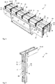
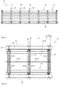
- Fig. 1 shows a perspective view of a shell mold 10 with twelve component chambers 16 arranged next to one another and opposite one another.
- the shell mold 10 comprises a molded base body 26, two rear walls 36 and delimiting bars 64.
- the molded base body 26 has horizontal wall sections 28, 30 and vertical wall sections 28, 32 of the front wall 28 of the molded base body 26 on.
- the component chambers 16 are thus designed for the formation of wall panels, in particular angled wall panels.
- the delimitation bars 64 are each formed from two side walls 38, 40.
- the mechanism for moving the side walls against each other is located inside the delimitation bars, so that the distances a1 and a2 (see also Fig. 12 ) can vary between two side walls.
- the rear walls 36 are shown slightly pivoted, as is necessary for stripping the formwork.
- the formwork is removed without giving away or rotating the formwork.
- the components (not shown) are removed in the position shown and then rotated and placed on a surface.
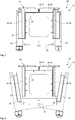
- FIG. 4 is a perspective view of the perimeter spar 64 of one embodiment Fig. 1 shown.
- the delimitation spar 64 is formed from several side walls 38, 40.
- a storage mechanism 66 which has guide plates 72 with elongated holes 74, is attached inside the delimitation beam 64.
- Guide elements 76 of the guide plates 72 are arranged in these elongated holes 74. These enable the side walls 38, 40 to be moved against one another by shifting the guide elements 76 in the elongated holes 74, whereby the guide plates 72 are moved in the vertical and horizontal directions and finally the side walls 38, 40 connected to the guide plates 72 are also moved.
- Each delimitation spar 64 can contain four guide plates 72, each with two elongated holes 74, in this vertical section.
- FIG. 3 shows a cross-section of an embodiment according to FIG Fig. 1 .
- the shell mold 10 is shown in a filling position 84 with vertically aligned rear walls 36.
- the component chamber 16 is thus formed by a plurality of side walls 38, 40, each a section rear wall 38, 42 and the mold base body 26 and the rear wall 36.
- FIG. 3 A representation of the form 10 according to Fig. 3 shows in a demolding position 88 Fig. 4 .
- the rear walls 36 are shown pivoted here.
- the rear walls 36 can be pivoted even further from the position shown, so that the angle between the rear wall 36 and the side walls 40 increases further. All other elements of this embodiment correspond to that of Fig. 3 .
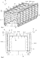
- Fig. 5 shows a perspective view of another embodiment of a mold 10 according to the invention in a filling position 84.
- the mold 10 comprises twelve component chambers 16, each of which is formed from a mold base body 26, a rear wall 36, several side walls 38, 40 and a section rear wall 38, 42.
- the rear wall 36 of all the component chambers 16 arranged on one side of the formwork mold 10 can be designed in one piece. This also applies to the molded body.
- each limiting strut 64 comprises an unlocking device 46 with a locking section 60, 62 and an unlocking section (not visible in this position of the unlocking device 46).
- control lever 44 and one associated unlocking device 46 per rear wall 36, which is preferably arranged in the area of the central component chamber 16.
- an unlocking device 46 and associated control lever 44 can be arranged only in every second component chamber 16, or the number of control levers 44 can differ from the number of unlocking devices 46.
- Fig. 6 shows a cross section through an embodiment according to Fig. 5 .
- the shell mold 10 is shown in a filling position 84, the rear walls 36 being oriented vertically.
- the unlockers 46 are arranged within the delimitation bars 64 and are in a not yet locked position so that the locking section 60 with the nose 62 is still visible.
- the nose 62 of the locking section 60 is arranged on the underside 50 of the unlocker 46.
- the unlocking section 56 with an overhang 58 is not visible, since this is arranged within the delimiting beam 64 and is covered by the side walls 38, 40.
- the unlocker 46 is rotated so that the top 52 of the unlocker 46 runs parallel to the side wall 40.
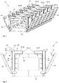
- Fig. 7 shows an embodiment of the form 10 shown in perspective Fig. 5 for a changed component geometry 12.
- This form form 10 is suitable for small-format angled wall panels.
- the rear walls 36 are shown pivoted outward.
- Each component chamber consists of several side walls 38, 40, each of a section rear wall 42, part of the molded body 26 and part of the rear wall 36.
- the delimitation bars 64 are formed from several side walls 38 or section side walls 40 and each contain an unlocking device 46.
- the control levers 44 are visible.
- a control lever 44 is assigned to each unlocking device 46 or each limiting bar 64, so that their number corresponds.
- FIG. 8 is a perspective cross-section of the embodiment of FIG Fig. 7 shown with pivoted rear walls 36.
- the control levers 44 are arranged on the rear walls 36.
- the unlockers 46 are shown in a rotating position so that only the locking portion 60 with nose 62 is visible.
- the unlocking section 56 with protrusion 58 of the unlocking device 46 is in this position inside the delimitation bar 46 and is covered by the side walls 38, 40.
- the formwork 10 in the embodiment shown is suitable for small-format, angled wall panels, since the section rear walls 38, 40 of the mirrored opposing component chambers 16 are far away from one another and do not touch.
- Fig. 9 shows an embodiment of a form 10 for large-format, angled wall panels. This can be seen in that the section rear walls 38, 42 of the component chambers 16 arranged opposite one another in a mirrored manner. In the position shown, the rear walls 36 are moved so close to the side walls 38 that the control levers 44 already engage in the parking mechanism 66, which is arranged within the delimitation bars 64. The control levers 44 engage in the guide elements 70 (not visible in this view) of the control levers 44. A control lever 44 is assigned to each delimitation beam 64. For a shell mold 10 with twelve component chambers 16 arranged opposite and mirrored next to one another, fourteen control levers 44 and fourteen unlockers 46 are accordingly arranged. A cross section through a form 10 according to Fig. 9 is in Fig. 10 shown.
- Fig. 11 shows a side view of a form of scarf Figures 9 and 10 .
- a side view of a rear wall 36 is shown, the unlockers 46 protruding above.
- An unlocking device 46 is arranged in each of the seven visible delimitation bars 64.
- FIG. 12 An associated section of a plan view of this embodiment of the form 10 according to Fig. 9 is in Fig. 12 shown.
- the detail shows four component chambers 16, only the horizontal wall section 30 of the front wall 28 of the basic molded body 26 of the basic molded body 26 of the shell mold 10 being visible.
- the horizontal wall section 30 is delimited by the side wall 38, ie the section rear wall 42 and two section side walls 40 and has a width a1.
- the storage mechanism 66 is located in the delimitation beam 64 between two side walls 38, 40, the delimitation beam 64 having a width a2.
- the control levers 44 which are attached to the rear wall 36, engage in the limiting beam 64.
- An unlocking device 46 is arranged in each delimitation beam 64.
- Fig. 13 shows a detail view of the vertical section of a delimitation beam 64, which is formed from two side walls 38, 40.
- the storage mechanism 66 is located inside the delimitation beam 64. This is formed from guide plates 42 with elongated holes 74. Guide elements 76 of the guide plates 72 are arranged within these elongated holes 74.
- the storage device includes four guide plates 72 with two elongated holes 74 each. Guide elements 70 for the control lever 44 are also arranged within the delimitation bar 64. These have a circular geometry and can be designed as rollers.
- Another perspective view of the delimitation beam 64 according to FIG Fig. 13 is in Fig. 14 shown. The four guide plates 72 are visible in this view.
- the control lever 44 comprises a sealing section 78 and a control section 80.
- the sealing section 78 is designed in a straight line and is located in the area of the control lever 44 which is closer to the rear wall 36 (not shown).
- the control section 80 is curved.
- the control lever 44 first engages with the control section 80 in the guide elements 70 (not shown) in the parking mechanism 66 (not shown).
- the travel speed of the side walls 36 is controlled via the storage mechanism via the curved control section 80.
- a different curved shape of the control section 80 of the control lever 44 accordingly leads to a different travel speed of the side walls 38.
- the control section 80 can also be partially straight, preferably in the area in which the control section 80 first engages the guide elements 72.
- Fig. 16 shows a further perspective view of such a control lever Fig. 15 .
- the control lever 44 is off Figures 15 and 16 shown again as a side view.
- the rectilinear partial area of the control section 80 at the right end of the control lever 44 is clearly visible in this view.
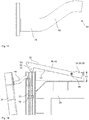
- Fig. 18 is an excerpt from Fig. 10 shown.
- the detailed view shows a section through the delimitation bar 64, the complete unlocking device 46 becoming visible.
- the unlocking device 46 has a rod-shaped base body 48 and two end sections 64.
- One end section 64 here forms the locking section 60, which is formed by a nose 62.
- the nose 62 is attached to the underside 50 of the unlocker 46.
- the other end area 54 of the unlocking device 46 forms an unlocking section 56, this being formed by a protrusion 58.
- This protrusion 58 is located on the upper side 52 of the unlocker 46.
- the unlocker 46 can rotate about an axis of rotation 96.
- the axis of rotation 96 is located near the end region 54 on which the unlocking section 56 is arranged.
- the rear wall 36 of the shell mold 10 is shown slightly inclined so that the control lever 44 does not yet engage with the control section 80 in the storage mechanism 66, ie in the guide elements 70.
- the unlocking device 46 is in a not yet locking position.
- the locking section 60 accordingly protrudes above the side walls 38, and the unlocking section 56 lies in a position within these side walls 38, that is to say within the delimitation beam 64.
- a further embodiment of a shell mold 10 according to the invention is shown in perspective.
- the embodiment shown has no control lever 44 and no unlocking device 46.
- several guide rods 102 are arranged on the rear wall 36, on which several wedges 100 are integrated.
- twelve wedges 100 and twelve associated hooks 98 are therefore required.
- the guide rod 102 with integrated wedges 100 can be moved in the longitudinal direction to the rear wall 96.
- the delimitation bars 64 are also formed by side walls 38, 40.
- FIG. 11 shows a perspective detailed view of the embodiment according to FIG Fig. 19 .
- a section of the rear wall 36 is shown, on which a guide rod 102 and a wedge 100 are visible.
- the guide rod 102 can be displaced in the longitudinal direction of the guide rod 102 in such a way that the wedge 100 moves in the direction of the hook 98.
- the wedge 100 first engages the hook with the smaller cross-sectional area.
- Fig. 21 shows a perspective longitudinal section through Fig. 20 by the hook 98.
- the wedge 100 By moving the guide rod 102 in the longitudinal direction, the wedge 100 can be moved in the direction of the hook 98.
- the hook can be jammed with the wedge to different degrees.
- the contact pressure of the rear wall 36 on the side walls 38 can thus be controlled and optimized via the wedge 100.
- the sealing function can be controlled individually by this contact pressure between the rear wall and the side wall.
- FIGs. 22a to 22c are sectional views through a mounting seat 104 of a component 12, 14 shown.
- the mounting seat 104 which is composed of a threaded sleeve 106 and a thickened anchor block 110.
- the anchor block 110 is cast in the interior of the component 12 and ensures anchoring of the threaded sleeve 106.
- a fixing element 114 is inserted into the holder receptacle 104 for the temporary attachment of the holder receptacle 104 in the formwork 10.
- the fixing element 114 comprises a threaded bolt 116 and a ferromagnetic thin and circular base disk 118.
- the threaded bolt 116 can be screwed into the threaded sleeve 106.
- a receiving area 112 of the front wall 28 has a recess area which can at least partially receive the base plate 118.
- the recess area prevents the position of the mounting receptacle 104 on the front wall 28 from changing.
- the position of the receiving area 112 is selected in such a way that, after the concrete element has been poured, the mounting receptacle is suitable for receiving the center of gravity of the component.
- a magnet 108 is arranged either as a permanent magnet or as an electromagnet, which can fasten the base plate 118 in a non-positive manner and thus fix the holder receptacle. Nonetheless, the base plate 118 can be permanently magnetic in order to adhere to a ferromagnetic receiving area 112.
- FIG 22c the mounting receptacle 104 cast into the component 12, 14 is shown in a sectional view.
- the fixing element 114 can be removed from the holder receptacle 104 and reused.
- a heavy-duty hook can be screwed into the threaded sleeve 106 of the holder receptacle 104 for transport, which serves as a point of application for a load lifting device such as a crane etc. in order to be able to lift the component in the center of gravity and move it in any position without force.
- a plurality of holder receptacles 104 can be provided, with the region of the component 14 around the holder receptacle connected thereto also having a recess region 120 that was effected by the base plate 118.
- the recess area 120 can be used to receive a cover made of plastic, stainless steel or the like, for example, in order to close the holder receptacle 104 after final assembly in order to produce a visible surface.
- the magnet arrangement of the mounting receptacle 104 ensures that the mounting receptacle 104 is positioned exactly for a center of gravity receptacle in the concrete element.
- a free-floating component By recording the center of gravity, a free-floating component can be moved in the assembly phase, for example, parallel to a bed of gravel and placed on it without sideshift, so that a gravel or concrete bed is not shifted and repositioning is possible without effort.
- the holder receptacle 104 can be used in a construction project to fasten further structural parts such as fastenings, railings, receptacles, etc.
Description
Die Erfindung betrifft eine Schalform zur Herstellung von mindestens einem Bauelement, insbesondere einem Betonbauelement mit definierten Kanten und/oder Fasen. Ebenso offenbart die Erfindung ein Verfahren zum Befüllen und Ausschalen einer derartigen Schalform.The invention relates to a shell mold for producing at least one structural element, in particular a concrete structural element with defined edges and / or bevels. The invention also discloses a method for filling and striking such a formwork form.
Mithilfe der vorgeschlagenen Schalform ist es möglich, Bauelemente mit Sichtoberflächen, Kanten und/oder Fasen herzustellen, die eine sehr hohe Güte aufweisen.With the help of the proposed shell shape, it is possible to produce components with visible surfaces, edges and / or bevels that have a very high quality.
Mauerscheiben werden dort eingesetzt, wo hohe Lasten durch großen Höhenversatz oder zusätzliche Verkehrsbelastung auftreten. Die Mauerscheiben dienen als Winkelstützelemente zum Abfangen von Geländesprüngen, die durch Hanglasten und/oder Verkehrslasten beansprucht werden, sie kommen in der Stadt-, Garten- und Landschaftsgestaltung zum Einsatz. Hierbei können ebene oder Eckelemente eingesetzt werden, wobei die üblichen Abmessungen bei einer Höhe von 55 cm bis 305 cm und einer Wanddicke von 12 cm liegen. Die Oberflächen sind hierbei als Sichtbeton ausgebildet.Wall washers are used where high loads occur due to large height differences or additional traffic loads. The wall washers serve as angled support elements to catch terrain jumps that are stressed by slope loads and / or traffic loads; they are used in urban, garden and landscape design. Here, flat or corner elements can be used, the usual dimensions being a height of 55 cm to 305 cm and a wall thickness of 12 cm. The surfaces are designed as exposed concrete.
Aus dem Stand der Technik sind Schalformen bekannt, bei welchen besonders bei der Herstellung von abgewinkelten Mauerscheiben, auch L-Steine genannt, eine der Oberflächenseiten durch eine Schaltafel und die andere Seite der Oberfläche händisch glatt gestrichen werden. Derartige Schalformen erlauben die Ausgestaltung lediglich einer Sichtseite der abgewinkelten Bauelemente mit einer hohen Oberflächengüte. Durch architektonische Gestaltungen kann es gewünscht sein, auch die der Hangseite zugewandte Oberfläche der Mauerscheibe mit einer optimalen Güte herzustellen. Hierbei werden besonders hohe Anforderungen an die Herstellung die im eingebauten Zustand sichtbaren Fasen und/oder Kanten der Mauerscheibe gestellt. Bei Einsatz einer Schalform mit Schaltafeln an jeder Sichtseite der Mauerscheibe, entsteht ein hoher Druck zwischen den gegenüberliegenden Oberflächen der Mauerscheibe und der Schaltafel. Beim Ausschalprozess besteht hierbei die Gefahr des Ausreißens oder Abreißens der Kanten und/oder Fasen der Mauerscheibe. Die Gefahr des Ausreisens / Abreisens der Fasen und/ oder Kanten kann dadurch minimiert werden, in dem das Betonbauelement bis zum erhärteten Zustand des Betons in der Schalform verbleibt.Formwork forms are known from the prior art in which, particularly in the production of angled wall panels, also called L-bricks, one of the surface sides is smoothed by hand by a panel and the other side of the surface. Such formwork forms allow the design of only one visible side of the angled components with a high surface quality. By means of architectural designs it may be desirable to produce the surface of the wall panel facing the slope side with an optimal quality. Particularly high demands are made on the production of the bevels and / or edges of the wall panel visible in the installed state. When using a formwork with formwork panels on each visible side of the wall panel, a high pressure is created between the opposing surfaces of the wall panel and the formwork panel. During the stripping process, there is a risk of the edges and / or bevels of the wall panel being torn out or torn off. The risk of the bevels and / or edges being torn off can be minimized in that the concrete component remains in the formwork until the concrete has hardened.
Der Beton beginnt in Abhängigkeit vom Zementgehalt bereits nach 1 bis 3 Stunden abzubinden, d. h. der Mörtel verliert seine Plastizität und beginnt zu Erstarren. Der Prozess des Abbindens ist nach 6 bis 8 Stunden abgeschlossen. Erst nach diesem Zeitraum treten die ersten Anzeichen einer Erhärtung ein. Der abgebundene, aber noch nicht erhärtete Beton hat die Plastizität des ungebundenen Betons verloren und behält seine Form, besitzt jedoch eine hohe Empfindlichkeit da der erstarrte aber noch nicht erhärtete Beton mechanischen Beanspruchungen noch nicht standhalten kann.Depending on the cement content, the concrete begins to set after 1 to 3 hours, ie the mortar loses its plasticity and begins to set. The process of setting is completed in 6 to 8 hours. Only after this period do the first signs of hardening appear. The hardened but not yet hardened concrete has lost the plasticity of the unbound concrete and retains its shape, but is highly sensitive because the hardened but not yet hardened concrete cannot withstand mechanical loads.
Nach ca. 24 Stunden ist ein üblicher Beton erhärtet, wobei der Beton die endgültige Nennfestigkeit jedoch noch nicht erreicht hat.Conventional concrete has hardened after approx. 24 hours, although the concrete has not yet reached its final nominal strength.
Beton hat in der Regel nach 28 Tagen seine Nennfestigkeit erreicht. Bei der Herstellung von Mauerscheiben wird in der Praxis schon nach 24 Stunden ausgeschalt, wobei das Betonprodukt danach noch nicht belastet werden darf, da wie beschrieben die endgültige Nennfestigkeit noch nicht erreicht ist. Vorheriges Ausschalen in einem Zeitraum kleiner 24 Stunden birgt die Gefahr des Abreisens / Ausreisens einzelner Abschnitte des Betonbauelements mit sich, wenn das Abtrennen des Betonbauelements von der Schalform eine zu große mechanische Belastung darstellt.As a rule, concrete has reached its nominal strength after 28 days. In the production of wall panels, the shuttering takes place after just 24 hours, whereby the concrete product must not be loaded afterwards, since the final nominal strength has not yet been reached, as described. Previous stripping within a period of less than 24 hours harbors the risk of individual sections of the concrete structural element leaving / leaving the building if the separation of the concrete structural element from the formwork form represents too great a mechanical load.
Eine wirtschaftliche Nutzung der Schalformen ist in der Praxis somit nur schwer möglich, da eine hohe Anzahl an Schalformen benötigt wird, um eine Vielzahl an Mauerscheiben in kurzer Zeit herzustellen.An economical use of the formwork forms is therefore difficult in practice, since a large number of formwork forms is required in order to produce a large number of wall panels in a short time.
Aus dem Stand der Technik sind Formen zur Herstellung von Betonfertigteilen bekannt. So offenbart die
Daneben zeigen die
Die
Die
In der
Die
Bei der Herstellung der Betonfertigteile in Batterieform nach der
In der
In der
In der
Die
Die
Die
In der
Die
In der japanischen Druckschrift
In der
Die
In der
Die
Ausgehend vom vorgenannten Stand der Technik ergibt sich das Problem, dass Mauerscheiben ohne konische Seitenflächen mit Sichtbetonoberflächen mit hoher Güte an mindestens zwei gegenüberliegenden Seiten und definierten Kanten und/oder Fasen mit derartigen aus dem Stand der Technik bekannten Schalformen schwer realisierbar sind, und für eine Massenproduktion nicht zufriedenstellend hergestellt werden können. Vorbekannte Schalformen weisen einen komplexen technischen Aufbau auf und erfordern aktiv betriebene Aktuatorelemente wie Hydraulikzylinder oder ähnliches. Zudem besteht das Problem, dass mit aus dem Stand der Technik bekannten Schalformen aufgrund der benötigten Zeit bis zum Ausschalen keine wirtschaftliche Herstellung möglich ist.Based on the aforementioned prior art, the problem arises that wall panels without conical side surfaces with exposed concrete surfaces of high quality on at least two opposite sides and defined edges and / or bevels with such formwork shapes known from the prior art are difficult to implement, and for mass production cannot be produced satisfactorily. Known forms of formwork have a complex technical structure and require actively operated actuator elements such as hydraulic cylinders or the like. In addition, there is the problem that with formwork forms known from the prior art, no economical production is possible due to the time required until the formwork is removed.
Aufgabe der Erfindung ist es daher, eine Schalform bereitzustellen, die es ermöglicht, Bauelemente wie Mauerscheiben mit Sichtoberflächen, Fasen und/oder Kanten an mindestens zwei gegenüberliegenden Oberflächen bereitzustellen, die eine hohe Güte und ohne Entschalkonizität wirtschaftlich in Serienfertigung herstellbar sind.The object of the invention is therefore to provide a form of formwork that makes it possible to provide components such as wall panels with visible surfaces, bevels and / or edges on at least two opposing surfaces, which are of high quality and can be economically produced in series production without de-calcification.
Diese vorstehenden Probleme werden durch eine Schalform und durch ein Verfahren zum Befüllen und Ausschalen einer derartigen Schalform nach den unabhängigen Ansprüchen gelöst. Vorteilhafte Weiterbildungen sind in den Unteransprüchen dargestellt.These above problems are solved by a formwork form and by a method for filling and stripping such a formwork form according to the independent claims. Advantageous further developments are presented in the subclaims.
Die Erfindung offenbart eine Schalform zur Herstellung von mindestens einem Bauelement, insbesondere einem Betonbauelement mit definierten Kanten und/oder Fasen, aufweisend zumindest eine Bauelementkammer, welche durch einen zumindest eine Vorderwand definierenden Formgrundkörper mindestens eine Rückwand und mehrere Seitenwände der Schalform begrenzt wird. Es ist zumindest eine Rückwand zum Öffnen bewegbar ausgestaltet, bevorzugt schwenkbar oder verschieblich gelagert, und mindestens eine Seitenwand verfahrbar ausgestaltet, wobei eine Abstellermechanik zwischen Rückwand und Seitenwand vorgesehen ist, die bei einer Öffnungsbewegung der Rückwand ein Verfahren der Seitenwand bewirkt.The invention discloses a shell mold for the production of at least one component, in particular a concrete component with defined edges and / or bevels, having at least one component chamber which is delimited by a mold base body defining at least one front wall, at least one rear wall and several side walls of the shell mold. At least one rear wall is designed to be movable, preferably pivotable or displaceable, and at least one side wall is designed to be movable, with a storage mechanism being provided between the rear wall and the side wall, which causes the side wall to move when the rear wall is opened.
Es wird vorgeschlagen, dass die mindestens eine verfahrbare Seitenwand über einen an der Rückwand gelagerten und angeordneten Steuerhebel als Teil der Abstellermechanik mechanisch verfahren wird, und der Steuerhebel mindestens einen gebogenen Steuerungsabschnitt zur Regelung der Verfahrgeschwindigkeit der Seitenwand sowie einen geradlinig ausgeführten Dichtungsabschnitt zur Verdichtung der Schnittstelle zwischen Rückwand und Seitenwand und Steuerung des Anpressdrucks umfasst.It is proposed that the at least one movable side wall is moved mechanically via a control lever mounted and arranged on the rear wall as part of the storage mechanism, and the control lever has at least one curved control section for regulating the speed of movement of the side wall and a straight-line sealing section for compressing the interface between Includes rear wall and side wall and control of the contact pressure.
Eine derartige Schalform ermöglicht es, rundum schalungsglatte Oberflächen eines Bauelements herzustellen, da durch das Wegfahren mindestens einer Seitenwand mindestens einer der Rückwand der Schalung der Druck zwischen der Schalung und der Oberfläche des Bauelements genommen wird. Eine Konizität der Seitenwände und Oberflächen zur erleichterten Entschalung ist nicht erforderlich, da zumindest an zwei, bevorzugt an drei Seitenflächen des Bauelements die Schalform bewegliche Schalwände aufweist, die bei der Entschalung zurückweichen. Wird die Schalform zur Entschalung gedreht, kann das Bauelement durch sein Eigengewicht nach Öffnen der Rück- und Seitenwand entschalt werden. Das Bauelement kann rundum Sichtbetonoberfläche aufweisen, die ebenso nachträglich durch ein Kugelstrahlverfahren behandelt werden können. Dies ermöglicht weiterhin ein früheres Ausschalen des Bauelements aus der kompletten Schalform. Besonders bei Bauelementen aus Beton kann bereits ausgeschalt werden, wenn der Beton noch nicht völlig erhärtet ist, d. h. in einem Zeitraum kleiner 24 Stunden nach dem Vergießen des Betons. Dadurch, dass das Bauelement durch die mindestens eine verfahrbare Seitenwand nicht mehr von allen zuvor eingeschalten Oberflächen in der Schalform eingespannt ist, kann ein Betonprodukt bereits in einem "weichen" Zustand ausgeschalt werden, da die mechanische Belastung zwischen der Schalform und dem Betonbauelement vor dem Ausschalen minimiert wird. Der Ausschalprozess erfolgt stufenweise, wobei zunächst die kleineren Schalelemente, d. h. mindestens eine Seitenwand, entgegen des Bauelements wegbewegt werden, um vor dem Ausschalen aus den größeren Schalelementen, wie mindestens einer Rückwand der Schalung, den Druck zwischen Schalung und Bauelement bereits zu minimieren. Durch die Ausgestaltung der Schalform mit mindestens einer verfahrbaren Seitenwand und mindestens einer verfahrbaren Seitenwand ist eine Entschalkonizität nicht mehr notwendig. Dies ermöglicht die Herstellung von Bauelementen mit schalungsglatten Oberflächen und zueinander rechtwinkligen Oberflächen, ohne dass eine konische Anordnung der Schalplatten zueinander notwendig ist. Das Bauelement kann demnach eine zu allen Oberflächen rechtwinklige Geometrie aufweisen. Das Ablösen der Schalung von einem von allen Seiten rechtwinkligen Bauelement stellt durch die Ausgestaltung von mindestens einer verfahrbaren Seitenwand kein Problem dar. Somit sind auch Einschnitte bzw. Hinterschnitte in das Bauelement möglich, da entsprechende Schalelemente herausgefahren bzw. verfahren werden können.Such a formwork shape makes it possible to produce smooth surfaces of a component all around, since the pressure between the formwork and the surface of the component is relieved by moving away at least one side wall of at least one of the rear wall of the formwork. A conical shape of the side walls and surfaces for easier removal of the formwork is not necessary, since the formwork form has movable formwork walls on at least two, preferably on three side surfaces of the structural element, which retract during formwork removal. If the formwork is rotated to remove the formwork, the structural element can be removed from the formwork by its own weight after opening the rear and side walls. The construction element can have exposed concrete surface all around, which can also be treated subsequently by a shot peening process. This also enables the component to be stripped from the complete formwork earlier. Particularly in the case of construction elements made of concrete, it is possible to shutdown when the concrete has not yet completely hardened, ie within a period of less than 24 hours after the concrete has been poured. The fact that the component is no longer clamped in the formwork form by all of the previously coated surfaces due to the at least one movable side wall, a concrete product can already be stripped in a "soft" state, since the mechanical load between the formwork form and the concrete construction element prior to stripping is minimized. The stripping process takes place in stages, with the smaller formwork elements, that is to say at least one side wall, initially being moved away against the structural element in order to be removed before stripping the larger formwork elements, such as at least one rear wall of the formwork, to minimize the pressure between the formwork and the component. As a result of the design of the shell shape with at least one movable side wall and at least one movable side wall, a de-formwork cone is no longer necessary. This enables the production of construction elements with smooth surfaces and surfaces at right angles to one another, without the need for a conical arrangement of the formwork panels with respect to one another. The component can accordingly have a geometry that is perpendicular to all surfaces. The detachment of the formwork from a building element that is rectangular on all sides is not a problem due to the design of at least one movable side wall. Thus, incisions or undercuts in the building element are also possible, since corresponding formwork elements can be extended or moved.
Die mindestens eine verfahrbare Seitenwand ist über einen an der Rückwand gelagerten und angeordneten Steuerhebel als Teil der Abstellermechanik mechanisch verfahrbar. Dies ermöglicht ein präzises und/oder konstantes Verfahren der mindestens einen Seitenwand. Existieren mehrere verfahrbare Seitenwände können all diese zentral über einen Steuerhebel bewegt werden. Ebenso ist es denkbar, jede Seitenwand individuell über jeweils einen Steuerhebel anzusteuern. Bei einer Schalform mit mindestens zwei nebeneinanderliegenden Bauelementkammern können die mittig zwischen den Bauelementkammern angeordneten Seitenwände, vorzugsweise zwei Seitenwände, mit einem einzigen Steuerhebel synchron gesteuert werden. Hierbei kann der Steuerhebel gespiegelt ansteuern, d. h. die beiden Seitenwände synchron aufeinander zu oder voneinander wegbewegen. Somit kann ein definiertes und synchrones Ablösen der Seitenwände von dem Bauelement vor dem Ausschalen erreicht werden.The at least one movable side wall can be moved mechanically as part of the storage mechanism via a control lever mounted and arranged on the rear wall. This enables a precise and / or constant movement of the at least one side wall. If there are several movable side walls, all of these can be moved centrally using a control lever. It is also conceivable to control each side wall individually using a control lever. In the case of a formwork with at least two adjacent component chambers, the side walls arranged centrally between the component chambers, preferably two side walls, can be controlled synchronously with a single control lever. Here, the control lever can control in a mirrored manner, i.e. H. move the two side walls synchronously towards or away from each other. Thus, a defined and synchronous detachment of the side walls from the component can be achieved before the formwork is removed.
Dadurch, dass der Steuerhebel an der bewegbaren Rückwand gelagert oder angeordnet ist, wird es ermöglicht, die Bewegung der Rückwand mit der Verschiebung der mindestens einen Seitenwand zu koppeln und zu synchronisieren. Dadurch, dass der Steuerhebel an der Rückwand angebracht ist erzeugt eine Bewegung der Rückwand synchron eine Bewegung mindestens einer mit dem Steuerhebel ansteuerbaren Seitenwand, so dass beim Öffnen der Rückwand die Seitenwand vom erstarrten Betonelement wegbewegt, bzw. beim Schließen der Rückwand die Seitenwand in die Abgießposition verfahren wird. Der Verfahrweg der Rückwand und der mindestens einen Seitenwand kann an verschiedene Anforderungen an die Oberflächen der Bauelemente angepasst werden. Es ist vorteilhaft denkbar, dass mehrere Seitenwände mit nur einer Bewegung einer Rückwand verfahren werden können, indem mehrere Steuerhebel an der einen Rückwand angebracht sind, die jeweils eine oder mehrere Seitenwände ansteuern. Somit ist es möglich, mehrere nebeneinanderliegende Bauelementkammern mit jeweils verfahrbaren Seitenwänden auszustatten. Eine Schalform mit zwei nebeneinanderliegenden Bauelementkammern besteht demnach aus einer Rückwand, die sich über beide Bauelementkammern erstreckt, drei an der Rückwand angebrachten Steuerhebeln und vier verfahrbare Seitenwände.The fact that the control lever is mounted or arranged on the movable rear wall makes it possible to couple and synchronize the movement of the rear wall with the displacement of the at least one side wall. Because the control lever is attached to the rear wall, a movement of the rear wall synchronously generates a movement of at least one side wall that can be controlled with the control lever, so that the side wall moves away from the solidified concrete element when the rear wall is opened, or the side wall into the pouring position when the rear wall is closed is proceeded. The travel of the rear wall and the at least one side wall can be different Requirements on the surfaces of the components are adapted. It is advantageously conceivable that several side walls can be moved with only one movement of a rear wall, in that several control levers are attached to the one rear wall, each of which controls one or more side walls. It is thus possible to equip several component chambers lying next to one another, each with movable side walls. A shell mold with two component chambers lying next to one another accordingly consists of a rear wall which extends over both component chambers, three control levers attached to the rear wall and four movable side walls.
Der Steuerhebel umfasst mindestens einen gebogenen Steuerungsabschnitt, sowie einen geradlinig ausgeführten Dichtungsabschnitt. Durch den Steuerungsabschnitt wird die Geschwindigkeit des Verfahrens der mindestens einen Seitenwand und der Rückwand geregelt. Durch den Dichtungsabschnitt erfolgt ein Anpressen der Rückwand in Richtung Bauelementkammer und damit an die Seitenwände. Die Schnittstelle zwischen Rückwand und Seitenwand wird hierbei verdichtet, wobei keine weitere Dichtung notwendig ist. Der Anpressdruck wird hierbei über die Fahrgeschwindigkeit und den Fahrweg der Rückwand gesteuert. Durch einen gebogenen Steuerungsabschnitt wird das Heran- oder Wegfahren der Rückwand sowie der Seitenwände präzise gesteuert und in der Geschwindigkeit variiert.The control lever comprises at least one curved control section as well as a rectilinear sealing section. The speed of the movement of the at least one side wall and the rear wall is regulated by the control section. The sealing section presses the rear wall in the direction of the component chamber and thus against the side walls. The interface between the rear wall and the side wall is compressed in this case, whereby no further seal is necessary. The contact pressure is controlled via the travel speed and the travel path of the rear wall. A curved control section precisely controls the approach and departure of the rear wall and the side walls and the speed is varied.
Vorteilhafterweise werden zuerst die kleinflächigen Bereiche der Schalung, wie die Seitenwände, und im Anschluss die größeren Oberflächenbereiche, wie die Rückwand, wegwärts vom Bauelement verfahren.Advantageously, first the small-area areas of the formwork, such as the side walls, and then the larger surface areas, such as the rear wall, are moved away from the component.
Durch das Wegschwenken der Rückwand vor dem kompletten Ausschalen des Bauelements wird zusätzlich der Druck zwischen Bauelement und Schalwand reduziert. Zudem wird das Entnehmen des Bauelements aus der Schalform erleichtert. Das Verfahren der Rückwand kann nach oder zeitgleich mit dem Verfahren mindestens einer Seitenwand erfolgen. Die Geschwindigkeit kann aneinander angepasst und gekoppelt werden. Die Abstellermechanik stellt eine Synchronisierung der Öffnungsbewegung der Rück- und Seitenwand her, wobei eine Fehlbedienung ausgeschlossen ist und eine rein mechanische Kopplung erfolgt. Somit werden die Seitenwände immer parallel mit der Rückwand verfahren und ein einfacher, robuster und sicherer Entschalvorgang kann gewährleistet werden.By pivoting the rear wall away before completely stripping the building element, the pressure between the building element and the shuttering wall is also reduced. In addition, the removal of the component from the shell mold is made easier. The rear wall can be moved after or at the same time as the movement of at least one side wall. The speed can be adapted to each other and coupled. The storage mechanism synchronizes the opening movement of the rear and side wall, preventing incorrect operation and a purely mechanical coupling. In this way, the side walls are always moved parallel to the rear wall and a simple, robust and safe demolding process can be guaranteed.
Außerdem kann es vorteilhaft sein, mindestens an zwei Seiten angebrachte Elemente der Schalung, beispielsweise die Rückwand und mindestens eine Seitenwand, zeitgleich vom Bauelement wegzubewegen und anschließend das Bauelement aus der Bauelementkammer auszuschalen.In addition, it can be advantageous to move elements of the formwork attached to at least two sides, for example the rear wall and at least one side wall, away from the component at the same time and then to remove the formwork from the component chamber.
Es kann somit ausgeschalt werden, ohne dass die definierten Fasen und/oder Kanten abreißen oder beschädigt werden. Dies kann bereits nach ca. 8 bis 18 Stunden nach dem Vergießen des Betons in die Schalform oder auch früher erfolgen. Dadurch kann ein wirtschaftlicher und zeitlich optimierter Einsatz einer Schalform erreicht werden.It can therefore be switched off without the defined chamfers and / or edges tearing off or being damaged. This can be done after approx. 8 to 18 hours after the concrete has been poured into the formwork or earlier. As a result, an economical and time-optimized use of a form mold can be achieved.
In einer bevorzugten Ausführungsform sind mindestens zwei Seitenwände der Schalform verfahrbar ausgestaltet. Der Prozess des Ausschalens kann somit weiter erleichtert werden. Die Druckverringerung zwischen der Schalform und dem Betonbauelement ist demnach optimal steuerbar, da an zwei gegenüberliegenden Seitenwänden zeitgleich der Druck zwischen Schalung und Betonbauelement genommen wird.In a preferred embodiment, at least two side walls of the shell mold are designed to be movable. The stripping process can thus be further facilitated. The pressure reduction between the formwork and the concrete building element can therefore be optimally controlled, since the pressure between the formwork and the concrete building element is taken at the same time on two opposite side walls.
Ebenso kann eine Schalform bereitgestellt werden, bei welcher zwei nebeneinanderliegende Bauelemente in zwei Bauelementkammern zeitgleich hergestellt werden können, wobei jeweils eine angrenzende Seitenwand an das jeweilige Bauteil verfahrbar ausgestaltet sein kann und die mittig liegende Seitenwand starr verbleibt. Ebenso ist es denkbar, auch die mittig zwischen zwei Bauelementkammern liegenden Seitenwände verfahrbar zu gestalten. Für beide parallel hergestellte Bauelemente können somit schalungsglatte Oberflächen mit definierten Kanten und/oder Fasen an mindestens zwei gegenüberliegenden Oberflächen der Bauelemente hergestellt werden. Beide Bauelemente können jeweils zueinander rechtwinklige Oberflächen aufweisen. So können mehrere beispielsweise abgewinkelte Bauelemente wie Mauerscheiben gefertigt werden, die nebeneinander eingebaut werden können, wobei die Seitenwände der benachbarten Bauelemente zumindest in einem Abschnitt über die komplette Höhe und / oder Breite in Kontakt stehen, ohne dass auf einer Seite ein Schlitz durch eine konische Seitenwand sichtbar zurück bleibt. Dies ermöglich die Fertigung und Errichtung von Trennwänden oder Abtrennungen aus Sichtbeton, die von beiden Seiten optisch ansprechende und lückenfreie Übergänge von einem zum anderen Bauelement ermöglichen. Es können somit Trennwände aus beispielsweise L-Steinen gefertigt werden, die von beiden Seiten unverfüllt, d. h. ohne Abdeckung mit Erdreich oder Ähnlichem, bleiben und eine Sichtbetonoberfläche aufweisen.Likewise, a formwork form can be provided in which two components lying next to one another can be produced at the same time in two component chambers, whereby an adjacent side wall can be designed to be movable on the respective component and the centrally located side wall remains rigid. It is also conceivable to make the side walls located centrally between two component chambers movable. For both components produced in parallel, smooth surfaces with defined edges and / or chamfers can thus be produced on at least two opposing surfaces of the components. Both components can each have surfaces at right angles to one another. For example, several angled components such as wall panels can be manufactured, which can be installed next to one another, with the side walls of the adjacent components being in contact at least in one section over the entire height and / or width without a slot through a conical side wall on one side remains visible. This enables the production and erection of partitions or partitions made of exposed concrete, which enable visually appealing and gap-free transitions from one component to the other on both sides. It can thus be made of L-bricks, for example, partition walls that remain unfilled from both sides, ie without covering with soil or the like, and have an exposed concrete surface.
In einer vorteilhaften Ausführungsform sind zwei gegenüberliegende Seitenwände einer Bauelementkammer relativ zueinander verschiebbar oder verschwenkbar, wodurch ein Abstand a1 zwischen den beiden Seitenwänden veränderbar ist. Somit wird es ermöglicht, zwei Seitenwände einer Bauelementkammer zeitgleich vom Bauelement weg zu bewegen. Dies kann über zwei Steuerhebel erfolgen, die jeweils eine Seitenwand ansteuern. In einer vorteilhaften Ausführungsform umfasst die Schalform zumindest zwei benachbarte Bauelementkammern und einen Begrenzungsholm zwischen den Bauelementkammern, an dem zwei Seitenwände angeordnet sind, wobei jeweils eine Seitenwand einer Bauelementkammer zugeordnet ist, wobei der Begrenzungsholm eine Abstellermechanik umfasst, um die beide Seitenwände relativ zueinander verfahrbar sind. Ein Abstand a2 zwischen beiden Seitenwänden, die einen Begrenzungsholm bilden, kann vergrößert oder verkleinert werden. Der Begrenzungsholm kann sich demnach verjüngen. Dies ermöglicht ein zeitgleiches Herstellen und Ausschalen von zwei benachbart angeordneten Bauelementen. Die kann ebenso auf eine Vielzahl an nebeneinanderliegenden Bauelementkammern skaliert werden, indem zwischen den Bauelementkammern je ein derartiger Begrenzungsholm vorhanden ist. Die Abstellermechanik dient zur Steuerung des Verfahrwegs der Seitenwände, wobei die Steuerung auch durch einen Steuerhebel, der in die Abstellermechanik eingreift, erfolgen kann. Um die Schalform nach dem Betonieren und Entschalen wieder zu reinigen ist es ebenso denkbar, dass der Begrenzungsholm entgegen der Vorderwand der Schalform derart zu verfahren, dass ein Spalt zwischen dem Begrenzungsholm mit den Seitenwänden und der Vorderwand entsteht. So kann diese Kante ausreichend gereinigt werden, um beim erneuten Betonieren erneut Bauelemente mit definierten und scharfen Kanten herzustellen.In an advantageous embodiment, two opposite side walls of a component chamber can be displaced or pivoted relative to one another, whereby a distance a1 between the two side walls can be changed. This makes it possible to move two side walls of a component chamber away from the component at the same time. This can be done using two control levers, each of which controls a side wall. In an advantageous embodiment, the formwork comprises at least two adjacent component chambers and a delimitation spar between the component chambers, on which two side walls are arranged, one side wall each being assigned to a component chamber, the delimitation spar comprising a storage mechanism around which the two side walls can be moved relative to one another. A distance a2 between the two side walls that form a delimitation spar can be increased or decreased. The delimitation spar can therefore taper. This enables the simultaneous production and stripping of two adjacent components. This can also be scaled to a large number of component chambers lying next to one another, in that such a delimitation bar is present between the component chambers. The storage mechanism is used to control the travel path of the side walls, and the control can also be carried out by a control lever which engages in the storage mechanism. In order to clean the formwork again after concreting and removing the formwork, it is also conceivable that the delimitation spar is moved against the front wall of the formwork form in such a way that a gap is created between the delimitation strut with the side walls and the front wall. In this way, this edge can be cleaned sufficiently so that building elements with defined and sharp edges can be produced again when concreting again.
In einer vorteilhaften Ausführungsform kann im Begrenzungsholm ein Haken angeordnet sein, der beim Schließen der Rückwand durch eine Ausnehmung der Rückwand hindurchgreift, wobei in oder auf der Rückwand ein Führungsstab mit integriertem Keil angeordnet ist, der lösbar in den Haken eingreifen kann, und der Führungsstab in oder auf der Rückwand verschiebbar angeordnet ist. Der Führungsstab mit integriertem Keil kann hierbei in Längsrichtung auf der Rückwand verschiebbar sein. Beim Schließen der Rückwand gegen den Begrenzungsholm greift der Haken des Begrenzungsholms durch eine Ausnehmung der Rückwand und umgreift den Führungsstab. Der Keil hat einen größeren Querschnitt als der Führungsstab. Bei der vorgeschlagenen Haken-Keil-Verriegelung greift der am Führungsstab geführte Keil beim Längsverschieben des Führungsstabs mit seiner kleineren Querschnittsfläche in den Haken des Begrenzungsholms ein. Durch die Neigung der Seitenwände des Keils kann der Anpressdruck der Rückwand in Richtung der Bauelementkammer gesteuert werden, in dem der Führungsstab verschoben wird und den Keil in den Haken treibt. Der Keil wird durch den Führungsstab längs auf der Rückwand verschoben, wobei durch die Bewegung die größer werdende Querschnittsfläche des Keils in den Haken eingepresst wird. Somit kann ein auch unter hohem Druck zuverlässiger Verschluss der Bauelementkammern sowie ein erleichtertes Öffnen und Wegklappen der Rückwand erreicht werden. Eine derartige Verbindung schließt auch eine mehrmals verwendete Schalform zuverlässig, da die Verbindung zum Nachspannen bzw. Vorspannen geeignet ist und an verschiedene Längen angepasst werden kann. Es ist ebenso denkbar, dass eine einzelne Seitenwand, die nicht mit dem Begrenzungsholm verbunden ist, aus ihrer 90°-Position gekippt werden kann, um diese Kante ebenso ausreichend zu reinigen. Dies kann beispielweise für die bodenseitige Seitenwand zutreffen, die in der Befüllposition parallel zum Boden angeordnet ist, und auf der der Begrenzungsholm gelagert ist. Während des Betonierens steht der Begrenzungsholm mit den Seitenwänden auf dieser bodenseitigen Seitenwand auf, sodass diese abgedichtet wird.In an advantageous embodiment, a hook can be arranged in the delimitation bar which, when the rear wall is closed, reaches through a recess in the rear wall, with a guide rod with an integrated wedge being arranged in or on the rear wall, which can detachably engage the hook, and the guide rod in or is arranged displaceably on the rear wall. The guide rod with an integrated wedge can be displaced in the longitudinal direction on the rear wall. When the rear wall is closed against the delimitation bar, the hook of the delimitation bar engages through a recess in the rear wall and engages around the guide rod. The wedge has a larger cross-section than the guide rod. In the proposed hook-and-wedge lock, the wedge guided on the guide rod engages with its smaller cross-sectional area in the hook of the delimitation bar when the guide rod is moved longitudinally. Due to the inclination of the side walls of the wedge, the contact pressure of the rear wall in the direction of the component chamber can be controlled by sliding the guide rod and driving the wedge into the hook. The wedge is displaced lengthways on the rear wall by the guide rod, with the increasing cross-sectional area of the wedge being pressed into the hook by the movement. Consequently a reliable closure of the component chambers, even under high pressure, as well as easier opening and folding away of the rear wall can be achieved. Such a connection also reliably closes a formwork form that is used several times, since the connection is suitable for re-tensioning or pre-tensioning and can be adapted to different lengths. It is also conceivable that a single side wall that is not connected to the delimitation beam can be tilted out of its 90 ° position in order to clean this edge sufficiently. This can apply, for example, to the bottom side wall, which is arranged parallel to the bottom in the filling position and on which the delimitation bar is mounted. During concreting, the delimitation spar with the side walls rests on this bottom side wall so that it is sealed.
In einer vorteilhaften Ausführungsform umfasst die Abstellermechanik Führungselemente zur Führung des Steuerhebels, insbesondere Führungsbleche mit Langlöchern und Führungselementen für diese Langlöcher, über welche die verfahrbaren Seitenwände steuerbar sind. Die Führungselemente der Steuerhebel können als Rollen oder kreisförmige Elemente ausgebildet sein, wobei der Steuerhebel zwischen mindestens zwei dieser Führungselemente einfädelt und von diesen geführt wird. Somit kann eine Schalform für mindestens zwei nebeneinanderliegende Bauelementkammern mit mindestens zwei verfahrbaren Seitenwänden bereitgestellt werden, die sich zwischen den Bauelementkammern befinden, ohne dass der Steuerhebel in die Bauelementkammer eingreift. Der Steuerhebel kann in den Spalt a2 zwischen den beiden Seitenwänden eingreifen. Dieser Spalt a2 wird durch den sogenannten Begrenzungsholm gebildet.In an advantageous embodiment, the parking mechanism comprises guide elements for guiding the control lever, in particular guide plates with elongated holes and guide elements for these elongated holes, via which the movable side walls can be controlled. The guide elements of the control levers can be designed as rollers or circular elements, the control lever threading between at least two of these guide elements and being guided by them. Thus, a form for at least two adjacent component chambers can be provided with at least two movable side walls which are located between the component chambers without the control lever engaging the component chamber. The control lever can engage in the gap a2 between the two side walls. This gap a2 is formed by the so-called limiting spar.
In einer vorteilhaften Ausführungsform ist zur Herstellung eines abgewinkelten Bauelements die Vorderwand des Formgrundkörpers abgewinkelt ausgeführt und umfasst mindestens einen vertikalen Wandabschnitt sowie mindestens einen horizontalen Wandabschnitt. Somit ist die Schalform im Speziellen für die Herstellung von abgewinkelten Mauerscheiben, insbesondere für L-Steine, geeignet. Ebenso ist es möglich, dass die Schalform einen vertikalen, einen horizontalen und einen geneigten Wandabschnitt umfasst. Der geneigte Wandabschnitt kann um einen Winkel 0° < α < 90° zum vertikalen Wandabschnitt geneigt sein. Vorteilhafterweise ist der geneigte Abschnitt zwischen dem horizontalen und dem vertikalen Abschnitt ausgebildet. Dies ermöglicht die Herstellung von L-Steinen mit einer besonders verdickten Wandstärke im Bereich des Übergangs zwischen vertikalem und horizontalem Wandabschnitt. Auf der gegenüberliegenden Seite zu diesem geneigten Wandabschnitt, sozusagen im Bereich der Rückseite der Schalung, kann die Bauelementkammer ebenso vertikal oder horizontal ausgebildet sein. Weiterhin bietet die Schalung die Möglichkeit, Lichtschächte, d. h. U-förmige Bauelemente herzustellen. Hierzu kann die Vorderwand des Formgrundkörpers aus einem horizontalen und zwei vertikalen Wandabschnitten bestehen.In an advantageous embodiment, to produce an angled component, the front wall of the molded base body is angled and comprises at least one vertical wall section and at least one horizontal wall section. Thus the form of the formwork is especially suitable for the production of angled wall panels, especially for L-stones. It is also possible that the shell shape comprises a vertical, a horizontal and an inclined wall section. The inclined wall section can be inclined at an angle of 0 ° <α <90 ° to the vertical wall section. The inclined section is advantageously formed between the horizontal and vertical sections. This enables the production of L-bricks with a particularly thickened wall thickness in the area of the transition between vertical and horizontal wall section. On the opposite side to this inclined wall section, so to speak in the area of the rear side of the formwork, the component chamber can also be designed vertically or horizontally. Furthermore, the formwork offers the possibility of producing light wells, ie U-shaped components. For this purpose, the front wall of the molded body can consist of one horizontal and two vertical wall sections.
So kann die Schalungsform konstruktiv in Einzelkomponenten zerlegbar sein, so dass mit einem mehrteiligen Zusammenbau in verschiedener Zusammenstellung unterschiedliche Bauelementegeometrien wie L-förmige Mauerscheiben unterschiedlicher Höhen oder U-förmige Betonelemente hergestellt werden können. Die Oberflächen der abgewinkelten Bauelementegeometrien können rechtwinklig zueinander ausgebildet sein. Bei L-förmigen Mauerscheiben können die umlaufenden Seitenwände des Fußbereichs konisch ausgebildet sein, so dass keine verfahrbaren Seitenwände im Fußbereich in der Schalform angeordnet sind, und durch eine Entschalkonizität ein leichtes Auslösen aus der Schalform möglich ist. Da in der Regel der Fußbereich einer L-Mauerscheibe im Erdreich verborgen ist, sind konisch verlaufende Seitenbereich der Fußplatte später unsichtbar. Somit kann eine L-förmige Mauerscheibe parallel Seitenflächen der aus dem Untergrund herausragenden Mauerscheibe und konische Seitenflächen der im Untergrund verborgenen Fußplatte aufweisen.The formwork can be structurally dismantled into individual components so that different component geometries such as L-shaped wall panels of different heights or U-shaped concrete elements can be produced with a multi-part assembly in various combinations. The surfaces of the angled component geometries can be formed at right angles to one another. In the case of L-shaped wall panels, the circumferential side walls of the foot area can be conical, so that no movable side walls are arranged in the foot area in the form of the formwork, and an easy release from the form of the formwork is possible due to a de-formconicity. Since the foot area of an L-wall washer is usually hidden in the ground, the conical side areas of the footplate are later invisible. Thus, an L-shaped wall panel can have parallel side surfaces of the wall panel protruding from the ground and conical side surfaces of the footplate hidden in the ground.
Vorteilhafterweise weist die Schalform eine schwenkbare Grundplatte bzw. Kopfplatte auf, die die Oberseite des abzugießenden Bauelements definiert und die somit aus Bodenplatte der Schalform ausgebildet ist. Die Kopfplatte kann zu Reinigungszwecken gekippt werden, wobei die verfahrbare Seitenwand in einer Befüllposition die Kopfplatte abdichtet und lagefixiert.The shell mold advantageously has a pivotable base plate or head plate which defines the top of the component to be cast and which is thus formed from the base plate of the shell mold. The top plate can be tilted for cleaning purposes, the movable side wall sealing the top plate in a filling position and fixing it in position.
In einer vorteilhaften Ausführungsform ist an einer der Bauelementkammern abgewandten Seite mindestens einer Seitenwand ein Entriegler angebracht, der die mindestens eine Rückwand in einer Befüllposition fixiert und in einer Entschalungsposition verschwenkbar oder ablösbar entriegelt. Dadurch wird sichergestellt, dass die Rückwand während des Befüllens der Schalform in der Position verbleibt, in der diese eine verdichtete Bauelementkammer ausbildet. Für eine Entschalungsposition kann durch Verschwenken des Entrieglers die Rückwand wieder freigegeben werden.In an advantageous embodiment, on a side facing away from the component chambers, an unlocking device is attached to at least one side wall, which fixes the at least one rear wall in a filling position and unlocks it in a pivoting or detachable position. This ensures that while the shell mold is being filled, the rear wall remains in the position in which it forms a compacted component chamber. For a demoulding position, the rear wall can be released again by swiveling the unlocker.
In einer vorteilhaften Ausführungsform ist der Entriegler in einem Begrenzungsholm zwischen zwei benachbarten Bauelementkammern angeordnet, an dem zwei Seitenwände angeordnet sind, wobei jeweils eine Seitenwand einer Bauelementkammer zugeordnet ist. Dadurch kann die Rückwand optimal in Richtung Bauelementkammer angepresst werden. Bei der Ausführung mehrere nebeneinander angeordneter Bauelementkammern und somit mehrerer Begrenzungsholme, kann die Rückwand gleichmäßig an alle Bauelementkammern gepresst werden, indem in jedem Begrenzungsholm ein Entriegler angeordnet ist.In an advantageous embodiment, the unlocking device is arranged in a delimitation beam between two adjacent component chambers, on which two side walls are arranged, one side wall each being assigned to a component chamber. This allows the rear wall to be optimally pressed in the direction of the component chamber. In the case of the design of several component chambers arranged next to one another and thus several delimiting bars, the rear wall can be pressed evenly against all of the component chambers by an unlocking device being arranged in each delimiting bar.
In einer vorteilhaften Ausführungsform weist der Entriegler einen Verriegelungsabschnitt bevorzugt in Form einer Nase sowie einen Entriegelungsabschnitt bevorzugt in Form eines Überstands auf, wobei bevorzugt der Entriegler einen stabförmigen Grundkörper aufweist und der Verriegelungsabschnitt und der Entriegelungsabschnitt an den beiden gegenüberliegenden Endbereichen des stabförmigen Grundkörpers, bevorzugt an der Oberseite und Unterseite der beiden gegenüberliegenden Endbereiche des Grundkörpers angeordnet sind. Bevorzugt überragt der Entriegler im eingebauten Zustand nur im Bereich des Vorsprungs eine Höhe h1 der Seitenwände, und befindet sich im übrigen Bereich in einer Höhe h2<h1. Der Entriegler kann hierbei schwenkbar gelagert sein und durch eine Rotation um eine Rotationsachse auch im Bereich des Verankerungsabschnitts die Höhe h1 der Seitenwände durch diese Rotation überragen. Die Lagerung des Entrieglers ist hierbei vorteilhafterweise näher am Entriegelungsabschnitt angeordnet, sodass durch eine Rotationsbewegung der Verriegelungsabschnitt eine größere Wegänderung erfährt als der Entriegelungsabschnitt.In an advantageous embodiment, the unlocking device has a locking section, preferably in the form of a nose, and an unlocking section, preferably in the form of a protrusion, the unlocking device preferably having a rod-shaped base body and the locking section and the unlocking section on the two opposite one another End regions of the rod-shaped base body are preferably arranged on the top and bottom of the two opposite end regions of the base body. In the installed state, the unlocking device preferably projects beyond a height h1 of the side walls only in the area of the projection, and is located in the remaining area at a height h2 <h1. The unlocking device can in this case be pivotably mounted and, by rotating about an axis of rotation, also in the area of the anchoring section protrude beyond the height h1 of the side walls as a result of this rotation. The mounting of the unlocking device is advantageously arranged closer to the unlocking section, so that the locking section experiences a greater change in path than the unlocking section as a result of a rotational movement.
In einer vorteilhaften Ausführungsform ist an jedem Begrenzungsholm ein Steuerhebel und/oder ein Entriegler angeordnet. Der Steuerhebel ist hierbei lösbar mit dem Begrenzungsholm verbunden, genauer gesagt greift der Steuerhebel in den Begrenzungsholm lösbar ein und ist vorteilhafterweise an der Rückwand gelagert. Besonders bei der Ausführung einer Schalform mit mehreren nebeneinanderliegenden Bauelementkammern kann somit der Verfahrweg der Rückwand sowie der Seitenwände über alle Bauelementkammern gleichmäßig gesteuert und synchron verfahren werden. Ebenso kann die Rückwand in einer Befüllposition optimal an jede Bauelementkammer gepresst werden, sodass die bestmögliche Dichtung zwischen Rückwand und der jeweiligen Seitenwand der jeweiligen Bauelementkammer erreicht wird.In an advantageous embodiment, a control lever and / or an unlocker is arranged on each delimitation bar. The control lever is detachably connected to the delimitation bar, more precisely the control lever engages in the delimitation bar in a detachable manner and is advantageously mounted on the rear wall. Particularly when designing a form with a plurality of component chambers lying next to one another, the travel path of the rear wall and the side walls can be uniformly controlled and moved synchronously over all component chambers. Likewise, the rear wall can be optimally pressed against each component chamber in a filling position, so that the best possible seal between the rear wall and the respective side wall of the respective component chamber is achieved.
In einer bevorzugten Ausführungsform umfasst die Schalform vier bis sechzehn, bevorzugt sechs bis vierzehn, insbesondere zwölf Bauelementkammern, wobei zwei Reihen nebeneinander angeordneter Bauelementkammern bevorzugt gespiegelt gegenüberliegend angeordnet sind. Besonders bei der Herstellung von abgewinkelten Mauerscheiben, wie L-Steinen, können so mehrere Mauerscheiben parallel gefertigt werden, wobei eine Massenproduktion durch die Batterieform der Schalung erreicht werden kann. Für ein handelsübliches mittleres L-Steinformat ergibt sich für eine Schalform für 12 L-Steine zuzüglich des Füllbetons ein Gewicht von ca. 6 t. Für kleine L-Steine liegt das Gewicht für die gleiche Anzahl an L-Steinen und Schalung bei ca. 2,5 t.In a preferred embodiment, the shell mold comprises four to sixteen, preferably six to fourteen, in particular twelve component chambers, two rows of component chambers arranged next to one another being arranged, preferably mirrored opposite one another. Particularly when producing angled wall panels such as L-bricks, several wall panels can be produced in parallel, with mass production being possible thanks to the battery form of the formwork. For a commercially available, medium-sized L-brick format, a formwork form for 12 L-bricks plus the filling concrete has a weight of approx. 6 t. For small L-stones, the weight for the same number of L-stones and formwork is approx. 2.5 t.
In einer vorteilhaften Ausführungsform ist die Rückwand aller nebeneinanderliegenden Bauelementkammern einstückig ausgebildet. Dies ermöglicht ein gleichzeitiges An- und Wegfahren der Rückwand für alle Bauelementkammern, so dass ein gleichzeitiges Befüllen und Entschalen aller Bauelementkammern stattfinden kann. Die Schalform kann somit wirtschaftlich für eine zeit- und kostensparende Serienproduktion genutzt werden.In an advantageous embodiment, the rear wall of all component chambers lying next to one another is formed in one piece. This enables the rear wall to be approached and removed simultaneously for all component chambers, so that all component chambers can be filled and removed at the same time. The formwork can thus be used economically for time and cost-saving series production.
In einer vorteilhaften Ausführungsform in der Vorderwand zumindest ein permanentmagnetischer oder magnetisierbarer und bevorzugt vertiefter Aufnahmebereich vorgesehen, in dem temporär eine einzugießende Halterungsaufnahme, insbesondere eine Gewindehülse, eines Bauelementes anordenbar ist, wobei bevorzugt der Aufnahmebereich an einer Stelle der Vorderwand angeordnet ist, die einer Schwerpunktsaufhängung der Halterungsaufnahme oder einer Schwerpunktskonstellation mehrerer Halterungsaufnahmen des Bauelements entspricht. Das Bauelement kann an der Halterungsaufnahme mit Hilfe z.B. eines Einschraubhakens, einer Lastöse oder eines Einsteckelements aufgenommen werden und in eine ausgerichtete und stabile Position gedreht und / oder in dieser Position gehalten werden. Bei Befestigung einer Transportschlaufe, Lastöse oder Einschraubhaken bietet es sich zur Entlastung der Gewindehülse und des umgebenden Betonmaterials an, zunächst eine Adapterscheibe vor Einschrauben einer Befestigungsschraube in eine Vertiefung rund um die Gewindehülse einzulegen, so dass seitliche Kräfte über die Adapterschraube großflächig auf die Betonwand übertragen werden kann. Gegebenenfalls kann eine derartige Adapterscheibe zusammen mit der Gewindehülse mit vergossen werden. Im Falle einer Mauerscheibe bzw. eines L-förmigen Bauelements kann dieses durch die Schwerpunktsanordnung der Halterungsaufnahme oder einem Ensemble von Halterungsaufnahmen derart angehoben und transportiert werden, dass aufgrund der Schwerpunktsaufnahme der zum Boden ausgerichtete Abschnitt der Mauerscheibe parallel zum Boden ausgerichtet bleibt bzw. ohne Kraftanstrengung das Bauelement in seiner räumlichen Lage ausgerichtet werden. Das Bauelement kann demnach plan auf dem Boden abgestellt werden. Dies ist besonders vorteilhaft, wenn derartige Mauerscheiben bzw. L-förmige Bauelemente in ein Kiesfundament eingebaut werden sollen, da die Kiesschüttung nicht durch asymmetrische Belastung verschoben wird. Dadurch, dass der bodenseitige Abschnitt der L-Form parallel zum Boden ausgerichtet ist, erfolgt kein punktuelles oder ungleichmäßiges Aufsetzen auf dem Kiesfundament. Demnach wird das Kiesfundament durch das Absetzen des Bauelements nicht uneben oder ungleichmäßig verformt. Ein ebenes Aufsetzen der Mauerscheibe bzw. des L-förmigen Bauelements wird gewährleitet, ohne dass das Kiesfundament nachbearbeitet und das Bauelement erneut versetzt werden muss. Dies stellt eine enorme Zeitersparnis beim Einbau derartiger Bauelemente dar und erleichtert den Setzvorgang derartiger Bauelemente. Vorteilhafterweise ist eine Halterungsaufnahme auf der Vorderseitenfläche mittig im unteren Drittel einer L-Mauerscheibe angeordnet.In an advantageous embodiment, at least one permanently magnetic or magnetizable and preferably recessed receiving area is provided in the front wall, in which A mounting receptacle to be cast in, in particular a threaded sleeve, of a component can be temporarily arranged, the receiving area preferably being arranged at a point on the front wall that corresponds to a center of gravity suspension of the mounting receptacle or a constellation of centers of gravity of several mounting receptacles of the component. The component can be picked up on the holder receptacle with the aid of, for example, a screw-in hook, a shackle or a plug-in element and rotated into an aligned and stable position and / or held in this position. When attaching a transport loop, shackle or screw-in hook, to relieve the threaded sleeve and the surrounding concrete material, it is advisable to first insert an adapter disk into a recess around the threaded sleeve before screwing in a fastening screw, so that lateral forces are transmitted over a large area to the concrete wall via the adapter screw can. If necessary, such an adapter disk can be cast together with the threaded sleeve. In the case of a wall panel or an L-shaped component, this can be lifted and transported by the arrangement of the center of gravity of the bracket receptacle or an ensemble of bracket receptacles in such a way that, due to the center of gravity, the section of the wall panel facing the ground remains aligned parallel to the ground or without exertion Component are aligned in its spatial position. The component can therefore be placed flat on the floor. This is particularly advantageous if such wall panels or L-shaped structural elements are to be built into a gravel foundation, since the gravel bed is not shifted by asymmetrical loading. Because the bottom-side section of the L-shape is aligned parallel to the ground, there is no punctual or uneven placement on the gravel foundation. Accordingly, the gravel foundation is not deformed unevenly or unevenly when the building element is set down. A level placement of the wall washer or the L-shaped building element is ensured without the gravel foundation having to be reworked and the building element having to be relocated. This represents an enormous time saving when installing such components and facilitates the setting process of such components. A holder receptacle is advantageously arranged on the front surface in the middle in the lower third of an L-wall washer.
Die Halterungsaufnahme kann bevorzugt eine Hülse mit einem Innengewinde und einen vergrößerten Ankerblock an einer Stirnseite der Hülse zur formschlüssigen Fixierung im Betonblock aufweisen, die in das Bauelement einbetoniert wird, und in der ein Einschraubhaken oder eine Lastöse mittels einer Schraube aufgenommen werden kann. Für einen Herstellvorgang kann zunächst in der Halterungsaufnahme ein Fixierelement eingesetzt werden, dass temporär in der Schalform angeordnet werden kann. So kann beispielsweise das Fixierelement einen Gewindebolzen und eine ferromagnetische Sockelscheibe aufweisen, wobei der Gewindebolzen in die Gewindehülse der Halterungsaufnahme eingeschraubt wird. Die Sockelscheibe kann beispielsweise als dünne Scheibe oder als Magnet ausgebildet sein. Die Sockelscheibe kann in einen vertieften Aufnahmebereich der Formwand eingesetzt werden, um eine lagerichtige Positionierung der Halterungsaufnahme zu gewährleisten, so dass die Halterungsaufnahme im Schwerpunkt des abgegossenen Betonproduktes angeordnet bleibt. Gleichwohl kann das Fixierelement auch frei an der Sockelwand positioniert werden. Vorteilhafterweise ist entweder das Fixierelement magnetisch, insbesondere die Sockelscheibe, oder in der Formwand ist im Aufnahmebereich ein Permanentmagnet oder ein Elektromagnet zur temporären Halterung der Halterungsaufnahme vorgesehen. Nach dem Abgießen des Betonelementes kann durch die Sockelscheibe im Bereich der Halterungsaufnahme ein bauteilseitiger Aufnahmebereich ausgebildet sein, der beispielsweise bei Nichtgebrauch des Halterungselements durch eine Kunststoffabdeckung überdeckt wird. Die Halterungsaufnahme kann nach Montage des Betonelements zur Befestigung von Konstruktionselementen beispielsweise einem Geländer, einer Halterung oder dergleichen weiterverwendet werden. Das Fixierelement kann einen Gewindebolzen mit einem möglichst dünn ausgebildeten Kopf als Sockelscheibe, beispielsweise einer angeschweißten oder sonst wie angebrachten Unterlegscheibe, umfassen, der in der Halterungsaufnahme aufgenommen wird. Das Fixierelement kann mehrmals zur Herstellung von Bauelementen wiederverwendet werden. Im Anschluss an das Abgießen und zumindest teilweise Aushärten des Betonproduktes kann das Fixierelement aus der Halterungsaufnahme entfernt werden, und es kann ein Einschraubhaken oder ein Einsteckelement in der Halterungsaufnahme befestigt werden, um das Betonelement in seiner Schwerpunktsaufhängung kraftsparend und frei lagedrehbar umsetzen zu könnenThe bracket receptacle can preferably have a sleeve with an internal thread and an enlarged anchor block on one end of the sleeve for positive fixation in the concrete block, which is concreted into the component and in which a screw-in hook or a lifting eye can be accommodated by means of a screw. For a manufacturing process, a fixing element can first be used in the holding fixture that can be temporarily arranged in the form of the shell. For example, the fixing element can have a threaded bolt and a ferromagnetic base disk, wherein the threaded bolt is screwed into the threaded sleeve of the bracket receptacle. The base plate can be designed, for example, as a thin plate or as a magnet. The base plate can be inserted into a recessed receiving area of the mold wall in order to ensure the correct positioning of the mounting receptacle so that the mounting receptacle remains arranged in the center of gravity of the poured concrete product. At the same time, the fixing element can also be positioned freely on the base wall. Advantageously, either the fixing element is magnetic, in particular the base plate, or a permanent magnet or an electromagnet is provided in the mold wall in the receiving area for the temporary holding of the holding receptacle. After the concrete element has been poured off, a component-side receiving area can be formed by the base plate in the area of the holder receptacle, which is covered by a plastic cover, for example when the holder element is not in use. After the concrete element has been installed, the holder receptacle can be used for fastening structural elements, for example a railing, a holder or the like. The fixing element can comprise a threaded bolt with a head that is as thin as possible as a base disk, for example a welded-on or otherwise attached washer, which is received in the mounting receptacle. The fixing element can be reused several times for the production of components. After the concrete product has been poured and at least partially hardened, the fixing element can be removed from the holder receptacle, and a screw-in hook or a plug-in element can be fastened in the holder receptacle in order to be able to relocate the concrete element in its center of gravity in a way that saves effort and is freely rotatable
Nach Einbau des Bauelements in ein Kiesfundament oder Ähnliches kann in dem Halterungsaufnahme ein Kunststoffeinsatz, ein Edelstahleinsatz oder Ähnliches eingeschraubt werden, um eine optisch ansprechende Verfüllung der Hülse zu schaffen, die dauerhaft dort angeordnet verbleibt. Für kompaktere und kleinere Mauerscheiben bzw. L-förmige Bauelemente kann lediglich ein derartiger Aufnahmebereich in dem vertikalen Bauelementabschnitt vorgesehen sein, da der Schwerpunkt im Bauelement liegt. Für größere und schlankere Bauelemente, bei denen der Schwerpunkt außerhalb des Bauelements angeordnet ist, können mehrere Halterungsaufnahmen in unterschiedlichen Bauteilabschnitten und Lagen vorgesehen sein. Eine Schwerpunktsaufhängung kann dann derart erreicht werden, dass alle Aufnahmebereiche mit Hebemitteln z.B. einer Kette oder Stahlseil verbunden werden und die Hebemittel miteinander verbunden und angehoben werden, so dass sich ein Schwerpunkt außerhalb des Betonproduktes ausbildet. Dadurch, dass die Halterungsaufnahme jedes Betonproduktes an einer identischen Position in der Schalform vorgesehen ist, können alle Betonprodukte identisch, d. h. mit einer identischen Position der Halterungsaufnahme, hergestellt werden. So können die Bauelemente im eingebauten Zustand nebeneinander auch mit einer Sichtfläche mit der Halterungsaufnahme verbleiben, da die Halterungsaufnahmen bei allen Bauelementen an der gleichen Position angeordnet sind und somit ein einheitliches Bild entsteht. Weitere Halterungsaufnahmen können z.B. für konstruktive Zwecke an beliebigen anderen Stellen des Bauelements, z.B. an der Vorder- oder Rückwand aber auch an Seitenwänden nach dem gleichen Prinzip eingebracht werden, um beispielsweise Geländer oder Verbindungselemente für andere Baukörper daran anschließen zu können.After installing the component in a gravel foundation or the like, a plastic insert, a stainless steel insert or the like can be screwed into the holder receptacle in order to create a visually appealing filling of the sleeve that remains permanently arranged there. For more compact and smaller wall panels or L-shaped components, only such a receiving area can be provided in the vertical component section, since the focus lies in the component. For larger and slimmer components, in which the center of gravity is arranged outside the component, several mounting receptacles can be provided in different component sections and positions. A center of gravity suspension can then be achieved in such a way that all receiving areas are connected with lifting means, for example a chain or steel cable, and the lifting means are connected to one another and lifted so that a center of gravity is formed outside of the concrete product. Because the holding fixture of each concrete product is provided at an identical position in the formwork mold, all concrete products can be produced identically, ie with an identical position of the holding fixture become. The components can thus remain next to one another in the installed state, even with a visible surface with the holder receptacle, since the holder receptacles are arranged in the same position for all components and thus a uniform image is created. Further mounting receptacles can, for example, be introduced for structural purposes at any other point on the component, for example on the front or rear wall but also on side walls according to the same principle, in order to be able to connect to railings or connecting elements for other structures.
In einer vorteilhaften Ausführungsform sind zumindest eine Vorderwand des Formgrundkörpers und mindestens eine benachbarte Seitenwand und/oder mindestens eine Rückwand und mindestens eine benachbarte Seitenwand jeweils rechtwinklig zueinander ausgebildet. Bevorzugt sind alle Seitenwände zu allen Rückwänden sowie zu allen Vorderwänden rechtwinklig ausgeführt, sodass die Vorderwände zu den Rückwänden der Schalform parallel verlaufen. Durch die Ausgestaltung der Schalform mit mindestens einer verfahrbaren Seitenwand ist eine Entschalkonizität nicht mehr notwendig. Dies ermöglicht die Herstellung von Bauelementen mit schalungsglatten Oberflächen, ohne dass eine konische Anordnung der Schalplatten zueinander notwendig ist. Das Bauelement kann demnach eine zu allen Oberflächen rechtswinklige Geometrie aufweisen. Das Ablösen der Schalung vom Bauelement stellt durch das Verfahren von mindestens einer Seitenwand kein Problem dar.In an advantageous embodiment, at least one front wall of the molded base body and at least one adjacent side wall and / or at least one rear wall and at least one adjacent side wall are each formed at right angles to one another. All side walls are preferably designed at right angles to all rear walls and to all front walls, so that the front walls run parallel to the rear walls of the formwork. As a result of the design of the formwork with at least one movable side wall, de-formwork conicity is no longer necessary. This enables construction elements with smooth formwork surfaces to be produced without the need for a conical arrangement of the formwork panels with respect to one another. The component can accordingly have a geometry that is right-angled to all surfaces. The detachment of the formwork from the component is not a problem due to the removal of at least one side wall.
Weiterhin offenbart die Erfindung ein Verfahren zum Befüllen und Ausschalen einer Schalform. Es wird vorgeschlagen, dass nach dem Befüllen der mindestens einen Bauelementkammer in einer Befüllposition mit einer horizontal nach oben geöffneten Befüllseite, die Schalform in der Befüllposition verbleibt, bis das Füllmaterial, bevorzugt der Beton, zumindest bereichsweise abgebunden ist und mindestens eine Seitenwand zum Ausschalen durch eine Öffnungsbewegung der Rückwand, bevorzugt durch ein Schwenken um einen Winkel α oder ein Kippen, verfahren wird. Somit kann der Druck zwischen dem zumindest bereichsweise abgebundenen Befüllmaterials und der Seitenwand verringert werden. Da dies vor dem kompletten Ausschalen der Schalform erfolgt, kann ein Bauelement mit definierten Kanten und/oder Fasen hergestellt werden. Vorteilhafterweise ist das Füllmaterial beim Verfahren der mindestens einen Seitenwand vollkommen abgebunden und zumindest teilweise erhärtet, sodass das Bauelement nach dem Verfahren einer Seitenwand nicht mehr plastifiziert und somit die Gestalt nicht mehr ändert. Durch das Verschwenken bzw. Verfahren der Rückwand können die Bauelemente mit Vakuumanlagen seitlich aus der Schalform herausgefahren und anschließend umgedreht und auf einem Untergrund abgelegt werden.The invention also discloses a method for filling and stripping a form of formwork. It is proposed that after filling the at least one component chamber in a filling position with a filling side that is open horizontally upwards, the formwork mold remains in the filling position until the filling material, preferably the concrete, has at least partially set and at least one side wall for stripping through a Opening movement of the rear wall, preferably by pivoting through an angle α or tilting, is moved. The pressure between the filling material, which is at least partially bound, and the side wall can thus be reduced. Since this takes place before the shuttering is completely stripped, a component with defined edges and / or bevels can be produced. Advantageously, when the at least one side wall is moved, the filler material is completely set and at least partially hardened so that the component no longer plasticizes after moving a side wall and thus no longer changes its shape. By pivoting or moving the rear wall, the components can be moved laterally out of the formwork with vacuum systems and then turned around and placed on a substrate.
In einer vorteilhaften Ausführungsform des Verfahrens erfolgt nach einem zumindest bereichsweisen Abbinden des Füllmaterials nach maximal 8 bis 12 Stunden, insbesondere weniger als 8 bis 12 Stunden, bevorzugt 5 Stunden ein Verschwenken der Schalform in eine Entschalungsposition, so dass die Befüllseite nach unten ausgerichtet ist. Dadurch kann in dieser Entschalungsposition die Schalform nach oben weggefahren werden, so dass die Bauelemente auf dem Untergrund verbleiben. Vorteilhafterweise ist das Füllmaterial beim Verschwenken der Schalform vollkommen abgebunden und zumindest teilweise erhärtet, sodass das Bauelement seine Selbsttragfähigkeit erreicht hat und nach dem Verschwenken in eine Entschalungsposition nicht mehr plastifiziert und somit die Gestalt nicht mehr ändert. Vorteilhafterweise rotiert die Schalung mit den Bauelementen um 180° und um die Massenschwerpunktsachse. Dies ist besonders dann von Vorteil, wenn es sich bei den Bauelementen um abgewinkelte Mauerscheiben, sogenannte L-Steine, oder um Lichtschächte, sogenannte U-Steine, handelt, da diese nach der Rotation um 180° bereits in einer stabilen Position auf dem Untergrund aufliegen. Das Drehen in die Entschalungsposition erfolgt durch das Eigengewicht, sodass extern aufgebrachte Kräfte zum Drehen der Schalform so gering wie möglich gehalten werden können. Anschließend können alle Bauelemente, falls es sich um eine Batterieschalung mit mehreren Bauelementen handelt, parallel ausgeschalt werden. Somit ist es nicht wie im Stand der Technik notwendig, einzelne Bauelemente mit einem Vakuumsauger oder Ähnlichem manuell aus der Schalung auszuheben und zum Abstellen auf einer Palette oder Ähnlichem zu drehen. Damit das Bauelement nicht während des Rotierens der Schalung bzw. direkt beim Erreichen der Entschalposition aus der Schalung herausfällt, kann an der Oberkante der Rückwand zumindest bereichsweise ein Überstand in Form einer überstehenden Kante oder Vorsprung angebracht werden, so dass bei geschlossener Rückwand das Bauelement gestützt und in der Schalung formschlüssig gehalten wird. Erst durch Verschwenken bzw. Auslenken der Rückwand nach Absetzen der Schalform in der Entschalposition wird das Bauelement durch Öffnen der Rück- und Seitenwand freigelegt und die Schalform kann nach oben verfahren werden. Das Bauelement verbleibt auf dem Untergrund in der abgestellten Position, beispielsweise konfektionietfertig auf einer Transportpalette.In an advantageous embodiment of the method, after the filling material has set at least in certain areas, after a maximum of 8 to 12 hours, in particular less than 8 to 12 hours, preferably 5 hours, the shell mold is pivoted into a Demoulding position so that the filling side is facing down. As a result, the formwork form can be moved upwards in this demolding position, so that the components remain on the ground. Advantageously, when the formwork is pivoted, the filler material is completely set and at least partially hardened, so that the component has reached its self-supporting capacity and is no longer plasticized after being pivoted into a formwork position and thus no longer changes its shape. The formwork with the components advantageously rotates through 180 ° and around the center of mass axis. This is particularly advantageous if the building elements are angled wall panels, so-called L-stones, or light shafts, so-called U-stones, as these are already in a stable position on the ground after rotating through 180 ° . It is turned into the demoulding position by its own weight, so that externally applied forces for turning the formwork form can be kept as low as possible. All components can then be switched off in parallel, if it is a battery formwork with several components. It is therefore not necessary, as in the prior art, to manually lift individual components out of the formwork with a vacuum suction device or the like and to turn them to place them on a pallet or the like. So that the component does not fall out of the formwork while the formwork is rotating or directly when the formwork is reached, a protrusion in the form of a protruding edge or projection can be attached to the upper edge of the rear wall at least in some areas, so that when the rear wall is closed, the component is supported and is held positively in the formwork. Only when the rear wall is pivoted or deflected after the formwork has been set down in the demolding position is the component exposed by opening the rear and side walls and the formwork can be moved upwards. The component remains on the ground in the parked position, for example ready to use on a transport pallet.
In einer vorteilhaften Ausführungsform des Verfahrens wird in der Entschalungsposition nach Aufsetzen der Schalform auf einem Untergrund die Rückwand vom Bauelement öffnend wegbewegt, insbesondere verschwenkt wird. Hierzu kann ein zuvor beschriebener Entriegler eingesetzt werden, der beim Absetzen der umgedrehten Schalform einen Kontakt mit dem Untergrund herstellt, und die Rück- und Seitenwände freigibt. Hierbei aktiviert der mindestens eine Steuerhebel die Abstellermechanik, wobei mindestens eine Seitenwand vom Bauelement wegbewegt wird und anschließend die Schalform zur Entschalung nach oben weggefahren wird. Der Prozess des Entriegelns sowie des Verfahrens der Rückwand und der mindestens einen Seitenwand kann somit automatisch durchgeführt werden. Ebenso wird die Rückwand somit zeitgleich von den mehreren nebeneinander angeordneten Bauelementkammern wegbewegt. Durch Verschenken der Rückwand werden über die Steuerhebel, die in die Abstellermechanik eingreifen, die Seitenwände bewegt. Die Rückwand kann schwenkbar an der Basiskonstruktion der Schalform angelenkt sein, und mittels zumindest einem querlaufenden Führungsstab an den die Seitenwände tragenden Begrenzungsholm verriegelt werden. Hierzu kann der Führungsstab Keilelemente aufweisen, die in Klauen oder Verriegelungshaken des Begrenzungsholms eingreifen kann. Durch eine längsaxial Verschiebung des Führungsstabs kann die Rückwand entriegelt und verschwenkt werden. Die Verriegelungshaken können nachjustierbar sein, um bei Verschleiß ein sicheres Öffnen und Schließen der Rückwand zu gewährleisten.In an advantageous embodiment of the method, in the demolding position, after the formwork has been placed on a substrate, the rear wall is moved away from the component in an opening manner, in particular pivoted. For this purpose, a previously described unlocking device can be used which, when the inverted form of the shell is set down, makes contact with the ground and releases the rear and side walls. Here, the at least one control lever activates the parking mechanism, with at least one side wall being moved away from the component and then the formwork being moved upwards for removal from the formwork. The process of unlocking and moving the rear wall and the at least one side wall can thus be carried out automatically. Likewise, the rear wall is thus simultaneously moved away from the multiple component chambers arranged next to one another. By giving away the back wall, the control levers, which engage in the storage mechanism that moves the side walls. The rear wall can be pivotably articulated to the basic structure of the shell mold and locked by means of at least one transverse guide rod to the delimitation beam carrying the side walls. For this purpose, the guide rod can have wedge elements which can engage in claws or locking hooks of the delimitation bar. The rear wall can be unlocked and pivoted by shifting the guide rod longitudinally. The locking hooks can be readjusted to ensure safe opening and closing of the rear wall when worn.
In einer vorteilhaften Ausführungsform des Verfahrens wird das mindestens eine Bauelement in der Entschalungsposition auf ein Transportvlies, bevorzugt einen Förderteppich mit Förderbürsten, abgelegt, wobei das mindestens eine Bauelement durch das Transportvlies entgegen des Formgrundkörpers wegbewegt wird. Ein Transportvlies umfasst eine Vielzahl von abgewinkelten Vlieshalmen, wobei eine auf das Vlies abgestellte Last durch ein Abwinkeln der Halme einen gewissen Weg in Abwinkelrichtung transportiert wird. Ein frisch ausgeschaltes Bauelement wird, abgestellt auf das Transportvlies, einen Transportweg in Vlieswinkelrichtung weg von einer Schalwand transportiert. Somit kann der Anpressdruck auf der letzten verbleibenden Fläche zwischen Bauelement und Schalung, d. h. zwischen der Vorderwand des Formgrundkörpers und des Bauelements, genommen werden. So können beispielsweise die sogenannten schwarzen Flecken auf der Betonoberfläche vermieden werden. Bei einer Schalform mit zwei gegenüberliegenden, gespiegelt angeordneten Bauelementkammern werden die Bauelemente, bevorzugt die angewinkelten Mauerscheinen bzw. L-Steine, gegeneinander wegbewegt. Hierbei können auf dem Untergrund Förderteppiche mit Förderbürsten mit 70° geneigten Bürsten eingesetzt werden. Die geneigten Förderbürsten sind vom Formgrundkörper wegwärts orientiert angeordnet, sodass die Bauelemente beim Abstellen auf diese Förderbüsten entgegen des Formgrundkörpers bewegt werden.In an advantageous embodiment of the method, the at least one component is placed in the demolding position on a transport fleece, preferably a conveyor carpet with conveyor brushes, the at least one component being moved away by the transport fleece against the main molded body. A transport fleece comprises a plurality of angled fleece stalks, with a load placed on the fleece being transported a certain distance in the angled direction by angling the stalks. A freshly disconnected component, placed on the transport fleece, is transported a transport path in the direction of the fleece angle away from a formwork wall. Thus, the contact pressure on the last remaining area between the component and formwork, i.e. H. between the front wall of the molded body and the component. For example, the so-called black spots on the concrete surface can be avoided. In the case of a shell shape with two opposing, mirrored component chambers, the components, preferably the angled wall sections or L-bricks, are moved away from one another. Conveyor carpets with conveyor brushes with brushes inclined at 70 ° can be used on the ground. The inclined conveyor brushes are oriented away from the molded body so that the components are moved against the molded body when they are placed on these conveyor brushes.
Eine derartige Schalung kann in einer Fertigungsstraße eingesetzt werden, wobei parallel unterschiedliche Schalungen zur Herstellung unterschiedlicher Bauteilgeometrien eingesetzt werden können. Beim Einsatz von Batterieschalungen mit mindestens 6 Bauelementkammern können auf einer Trasse die Bauelemente mit gängigen Abmessungen und großer Stückzahl hergestellt werden, und parallel Sonderbauteilformen gefertigt werden. Nach dem Betonieren können die Schalungen in einem mit Umluft beheizten Hochregallager gelagert werden. Ebenso können die Bauteile nach weniger als 8 Stunden, insbesondere nach 5 Stunden in einer Teilaushärtephase bereits ausgeschalt und ohne die Schalungen in diesem Hochregallager gelagert werden. Da die Entschalung ohne mechanische Beanspruchung der Bauelemente stattfindet, ist eine frühe Entschalung möglich, so dass die Fertigungskapazität erhöht werden kann. Die Restaushärtung kann im Hochregallager erfolgen, wobei nach zumindest 24 Stunden eine Vollaustrocknung erreicht werden kann.Such formwork can be used in a production line, with different formworks being able to be used in parallel to produce different component geometries. When using battery molds with at least 6 component chambers, the components with common dimensions and large numbers can be produced on a route, and special component shapes can be produced in parallel. After concreting, the formwork can be stored in a high-bay warehouse heated with circulating air. Likewise, after less than 8 hours, in particular after 5 hours in a partial curing phase, the components can already be stripped and stored in this high-bay warehouse without the formwork. Since the formwork is removed without mechanical stress on the components, an early formwork removal is possible, so that the production capacity can be increased. The residual hardening can take place in the high-bay warehouse, whereby complete drying can be achieved after at least 24 hours.
Eine derartige automatisierte Fertigungsstraße kann zwei oder mehrere Schalformvorbereitungsstraßen umfassen, in denen die Schalform gereinigt, gewartet und bewehrt wird. In der Bewehrung kann ein Armierstahl in die Schalform eingebracht werden, die die innere Stahlkonstruktion des Bauelements definiert. Hierbei können die temporär befestigbaren Halterungsaufnahmen in der Schalform angeordnet werden. Nach einem Transfer zur Betonabfüllanlage wird die Schalform befüllt, hiernach verdichtet und in sogenannten Härtplätzen zur Teilaushärtung verbracht. Dort kann diese für eine Teilhärtezeit von 5 oder mehr Stunden verbleiben, bis die Oberfläche der Bauelemente derart ausgehärtet ist, dass eine Entschalung möglich ist. Eine Entschalung erfolgt durch eine 180° Drehung entlang der Längsachse der Schalform, und einem Absetzen der Bauelemente durch ihr Produkteigengewicht auf einer Palette oder einer Entschalungsplatte. Hierdurch sind die mehreren parallel hergestellte Bauelemente auf einer Platte angeordnet. Diese können in einem vorzugsweise beheizten Hochregallager bis zur Endaushärtung von 24 Stunden oder mehr gelagert und anschließend für eine Auslieferung konfektioniert. Die Schalform wird einer Reinigung zugeführt.Such an automated production line can comprise two or more formwork preparation lines, in which the formwork form is cleaned, serviced and reinforced. Reinforcing steel can be inserted in the form of the formwork, which defines the inner steel structure of the building element. Here, the temporarily attachable holder receptacles can be arranged in the form of a shell. After a transfer to the concrete filling plant, the formwork form is filled, then compacted and placed in so-called hardening stations for partial curing. This can remain there for a partial hardening time of 5 or more hours until the surface of the components has hardened in such a way that the formwork can be removed. The formwork is removed by rotating it 180 ° along the longitudinal axis of the formwork and placing the components on a pallet or formwork panel using their own weight. As a result, the multiple components produced in parallel are arranged on a plate. These can be stored in a preferably heated high-bay warehouse until they have hardened for 24 hours or more and then made up for delivery. The mold is sent to a cleaning facility.
Weitere Vorteile ergeben sich aus der vorliegenden Zeichnungsbeschreibung. In den Zeichnungen sind Ausführungsbeispiele der Erfindung dargestellt. Die Zeichnungen, die Beschreibung und die Ansprüche enthalten zahlreiche Merkmale in Kombination. Der Fachmann wird die Merkmale zweckmäßigerweise auch einzeln betrachten und zu sinnvollen weiteren Kombinationen zusammenfassen.Further advantages result from the present description of the drawings. Exemplary embodiments of the invention are shown in the drawings. The drawings, the description and the claims contain numerous features in combination. The person skilled in the art will expediently also consider the features individually and combine them into useful further combinations.
Es zeigen:
- Fig. 1:
- eine perspektivische Darstellung einer Ausführungsform einer erfindungsgemäßen Schalform mit zwölf Bauelementkammern, welche nebeneinander und gespiegelt gegenüberliegend angeordnet sind;
- Fig. 2:
- einen Begrenzungsholm einer Schalform nach
Fig. 1 mit Abstellermechanik; - Fig. 3:
- einen Querschnitt einer Schalform nach
Fig. 1 in einer Befüllposition; - Fig. 4:
- einen Querschnitt durch eine Schalform nach
Fig. 1 in einer Entschalungsposition; - Fig. 5:
- eine perspektivische Darstellung einer weiteren Ausführungsform einer erfindungsgemäßen Schalform mit zwölf nebeneinander und gespiegelt gegenüberliegend angeordneten Bauelementkammern;
- Fig. 6:
- einen Querschnitt durch eine Schalform nach
Fig. 5 in einer Befüllposition; - Fig. 7:
- eine weitere, perspektivisch dargestellte Ausführungsform einer erfindungsgemäßen Schalform für kleinformatige abgewinkelte Mauerscheiben dargestellt mit geöffneten Rückwänden;
- Fig. 8:
- einen Querschnitt durch eine Schalform nach
Fig. 7 ; - Fig. 9:
- eine weitere, perspektivisch dargestellte Ausführungsform einer erfindungsgemäßen Schalform für großformatige abgewinkelte Mauerscheiben, dargestellt mit leicht geöffneter Rückwand;
- Fig. 10:
- einen Querschnitt durch eine Schalform nach
Fig. 9 ; - Fig. 11:
- eine Seitenansicht in Längsrichtung einer Schalform nach
Fig. 9 ; - Fig. 12:
- einen Ausschnitt einer Draufsicht einer Schalform nach
Fig. 9 ; - Fig. 13:
- einen vertikalen Abschnitt einer Ausführungsform eines Begrenzungsholms in einer Frontansicht;
- Fig. 14:
- eine Ansicht des Begrenzungsholms aus
Fig. 13 ; - Fig. 15:
- eine Ausführungsform eines Steuerhebels;
- Fig. 16:
- eine weitere Ansicht einer Ausführungsform eines Steuerhebels nach
Fig. 15 ; - Fig. 17:
- einen Seitendarstellung eines Steuerhebels nach
Fig. 15 und Fig. 16 ; - Fig. 18:
- einen Detailausschnitt aus
Fig. 10 mit kompletter Darstellung des Entrieglers; - Fig. 19:
- eine weitere, perspektivisch dargestellte Ausführungsform einer erfindungsgemäßen Schalform mit vier Bauelementkammern und einer Haken -Keil Verriegelung der Rückwand;
- Fig. 20:
- eine perspektivische Detailansicht aus
Fig. 19 der Haken-Keil-Verriegelung; - Fig. 21:
- eine perspektivische Schnittdarstellung der Ausführungsform aus
Fig. 19 mit Darstellung der Haken-Keil-Verriegelung; - Fig. 22:
- eine Schnittdarstellung durch eine Halterungsaufnahme eines Bauelements zur Schwerpunktlagerung des Bauelements
- Fig. 1:
- a perspective view of an embodiment of a form shell according to the invention with twelve component chambers, which are arranged side by side and mirrored opposite one another;
- Fig. 2:
- a delimitation beam according to a form of scarf
Fig. 1 with storage mechanism; - Fig. 3:
- a cross section of a form of scarf
Fig. 1 in a filling position; - Fig. 4:
- a cross section through a form of scarf
Fig. 1 in a release position; - Fig. 5:
- a perspective view of a further embodiment of a form of the invention with twelve side by side and mirrored opposite arranged component chambers;
- Fig. 6:
- a cross section through a form of scarf
Fig. 5 in a filling position; - Fig. 7:
- a further embodiment, shown in perspective, of a form of shell according to the invention for small-format angled wall panels shown with open rear walls;
- Fig. 8:
- a cross section through a form of scarf
Fig. 7 ; - Fig. 9:
- a further embodiment of a form of shell according to the invention, shown in perspective, for large-format angled wall panels, shown with a slightly open rear wall;
- Fig. 10:
- a cross section through a form of scarf
Fig. 9 ; - Fig. 11:
- a side view in the longitudinal direction of a form of scarf
Fig. 9 ; - Fig. 12:
- a section of a top view of a form of scarf
Fig. 9 ; - Fig. 13:
- a vertical section of an embodiment of a delimitation bar in a front view;
- Fig. 14:
- a view of the boundary spar
Fig. 13 ; - Fig. 15:
- an embodiment of a control lever;
- Fig. 16:
- a further view of an embodiment of a control lever according to
Fig. 15 ; - Fig. 17:
- a side view of a control lever
FIGS. 15 and 16 ; - Fig. 18:
- a detail section
Fig. 10 with complete representation of the unlocker; - Fig. 19:
- a further embodiment, shown in perspective, of a form shell according to the invention with four component chambers and a hook-wedge locking the rear wall;
- Fig. 20:
- a perspective detailed view from
Fig. 19 the hook and wedge lock; - Fig. 21:
- a perspective sectional view of the embodiment
Fig. 19 showing the hook and wedge lock; - Fig. 22:
- a sectional view through a holder receptacle of a component for supporting the center of gravity of the component
In
Eine Darstellung der Schalform 10 nach
In
Einen zugehörigen Ausschnitt einer Draufsicht auf diese Ausführungsform der Schalform 10 nach
In
In
In
In den
In der
In
- 1010
- SchalformScarf shape
- 1212
- BauelementComponent
- 1414th
- BetonbauelementConcrete building element
- 1616
- BauelementkammerComponent chamber
- 1818th
- KanteEdge
- 2020th
- Fasechamfer
- 2222nd
- Füllmaterialfilling material
- 2424
- Betonconcrete
- 2626th
- FormgrundkörperMold body
- 2828
- Vorderwand des FormgrundkörpersFront wall of the molded body
- 3030th
- horizontaler Wandabschnitt der Vorderwandhorizontal wall section of the front wall
- 3232
- vertikaler Wandabschnitt der Vorderwandvertical wall section of the front wall
- 3434
- Geneigter Abschnitt des FormgrundkörpersInclined section of the molded body
- 3636
- RückwandBack wall
- 3838
- SeitenwandSide wall
- 4040
- AbschnittsseitenwandSection sidewall
- 4242
- AbschnittsrückwandSection back wall
- 4444
- SteuerhebelControl lever
- 4646
- EntrieglerUnlocker
- 4848
- stabförmiger Grundkörperrod-shaped body
- 5050
- Unterseite des EntrieglersUnderside of the unlocker
- 5252
- Oberseite des EntrieglersTop of the unlocker
- 5454
- Endbereiche des EntrieglersEnd areas of the unlocker
- 5656
- Entriegelungsabschnitt des EntrieglersUnlocking section of the unlocker
- 5858
- Überstand/VorsprungOverhang / projection
- 6060
- Verriegelungsabschnitt des EntrieglersLocking section of the unlocker
- 6262
- Nasenose
- 6464
- BegrenzungsholmDelimitation beam
- 6666
- Absteller/ AbstellermechanikStorage / storage mechanism
- 6868
- Kern des AbstellersCore of the store
- 7070
- Führungselemente für SteuerhebelGuide elements for control levers
- 7272
- Führungsbleche des AbstellersGuide plates of the shelf
- 7474
- LanglochLong hole
- 7676
- Führungselemente der FührungsblecheGuide elements of the guide plates
- 7878
- Dichtungsabschnitt des SteuerhebelsSeal portion of the control lever
- 8080
- Steuerungsabschnitt des SteuerhebelsControl section of the joystick
- 8282
- UntergrundUnderground
- 8484
- BefüllpositionFilling position
- 8686
- BefüllseiteFilling side
- 8888
- EntschalungspositionRelease position
- 9090
- TransportvliesTransport fleece
- 9292
- FörderteppichConveyor carpet
- 9494
- FörderbürstenConveyor brushes
- 9696
- RotationsachseAxis of rotation
- 9898
- Hakenhook
- 100100
- Keilwedge
- 102102
- FührungsstabManagement staff
- 104104
- HalterungsaufnahmeBracket mount
- 106106
- GewindehülseThreaded sleeve
- 108108
- Magnetmagnet
- 110110
- AnkerblockAnchor block
- 112112
- AufnahmebereichRecording area
- 114114
- FixierelementFixing element
- 116116
- GewindebolzenThreaded bolt
- 118118
- Ferromagnetische SockelscheibeFerromagnetic base plate
- 120120
- Vertiefungsbereich des BetonelementsRecessed area of the concrete element
Claims (13)
- Formwork mould (10) for manufacturing at least one structural element (12), in particular a concrete structural element (14) with defined edges (18) and/or bevels (20), having at least one structural element chamber (16) which is limited by a basic mould body (26) defining at least one front wall (28), at least one rear wall (36) and several side walls (38) of the formwork mould (10), at least one rear wall (36) being designed movable for opening, preferably mounted swivellably or displaceably, and at least one side wall (38) being designed movable, a release mechanism (66) being provided between rear wall (36) and side wall (38) which effects a movement of the side wall (38) in an opening movement of the rear wall (36), characterized in that the at least one movable side wall (38) is moved mechanically using a control lever (44) mounted and arranged on the rear wall (36) as part of the release mechanism (66), and the control lever (44) comprises at least a curved controlling section (80) for regulating the movement speed of the side wall (38) and a straightly designed sealing section (78) for sealing the interface between rear wall and side wall and for control of the contact pressure.
- Formwork mould (10) according to claim 1, characterized in that at least two side walls (38) are designed movable.
- Formwork mould (10) according to one of the preceding claims, characterized in that two opposite side walls (38) of a structural element chamber (16) are displaceable or swivellable relative to one another, whereby a distance (a1) between the two side walls (38) is variable.
- Formwork mould (10) according to one of the preceding claims, characterized in that the formwork mould (10) comprises at least two adjacent structural element chambers (16) and a bounding waler (64) is arranged between the structural element chambers (16) on which two side walls (38) are arranged, one side wall (38) being associated with one structural element chamber (16) and the bounding waler (64) comprising the release mechanism (66) for moving the two side walls (38) relative to one another.
- Formwork mould (10) according to claim 4, characterized in that at least one hook (98) is arranged in the bounding waler (64) which during closing of the rear wall (36) passes through a cut-out of the rear wall (36), where in or on the rear wall (36) a guide rod (102) with integrated wedge (100) is arranged which detachably engages in the hook (98), and the guide rod (102) is displaceably arranged in or on the rear wall (36).
- Formwork mould (10) according to one of the preceding claims, characterized in that the release mechanism (66) comprises guide elements (70) for guiding the control lever (44), in particular guide plates (72) with slots (74) and guide elements (76) for these slots (74) using which the movable side walls (38) are controllable.
- Formwork mould (10) according to one of the preceding claims, characterized in that for manufacture of an angled structural element (12), the front wall (28) of the basic mould body (26) is designed angled and comprises at least one vertical wall section (32) and at least one horizontal wall section (30).
- Formwork mould (10) according to one of the preceding claims, characterized in that the formwork mould (10) comprises four to sixteen, preferably six to fourteen, in particular twelve structural element chambers (16), where two rows of structural element chambers (16) arranged next to one another are preferably arranged opposite in mirror-inverted manner.
- Formwork mould (10) according to claim 8, characterized in that the rear wall (36) of all adjoining structural element chambers (16) is designed in one piece.
- Formwork mould (10) according to one of the preceding claims, characterized in that at least one permanently magnetic or magnetizable and preferably recessed receiving area (112) is provided in the front wall (28), in which a holding element receptacle (104) to be cast, in particular a threaded sleeve (106), of a structural element (14) is temporarily arrangeable, the receiving area (112) preferably being arranged at a point of the front wall (28) which corresponds to a centre-of-gravity suspension of the holding receptacle (104) or to a centre-of-gravity constellation of several holding element receptacles (104) of the structural element (14).
- Method for filling and stripping of a formwork mould (10) according to one of the aforementioned claims, wherein after the filling of the at least one structural element chamber (16) in a filling position (84) with a filling side (86) opened horizontally upwards, the formwork mould (10) remains in the filling position (84) until the filling material (22), preferably concrete (24), is set in at least some areas and at least one side wall (38) is moved for stripping by an opening movement of the rear wall (36), preferably by swivelling about an angle α or by tilting.
- Method for filling and stripping of a formwork mould (10) according to claim 11, characterized in that after setting of the filling material (22) at least in some areas after a maximum of 8 to 12 hours, in particular less than 5 hours, the formwork mould (10) is swivelled into a stripping position (88) so that the filling side (86) is oriented downwards.
- Method according to claim 12 for filling and stripping of a formwork mould (10), characterized in that the rear wall (36) is moved clear in opening manner from the structural element (12), in particular swivelled, in the stripping position (88) after setting down of the formwork mould (10) on a ground surface (82), the at least one control lever (44) activating the release mechanism (66) and at least one side wall (38) being moved clear from the structural element (12) and subsequently the formwork mould (10) being moved upwards clear for stripping.
Priority Applications (1)
| Application Number | Priority Date | Filing Date | Title |
|---|---|---|---|
| PL16182990T PL3147094T3 (en) | 2015-08-07 | 2016-08-05 | Formwork mould for wall panel |
Applications Claiming Priority (1)
| Application Number | Priority Date | Filing Date | Title |
|---|---|---|---|
| DE102015113077.7A DE102015113077B4 (en) | 2015-08-07 | 2015-08-07 | Formwork form for a building element and method for stripping |
Publications (3)
| Publication Number | Publication Date |
|---|---|
| EP3147094A2 EP3147094A2 (en) | 2017-03-29 |
| EP3147094A3 EP3147094A3 (en) | 2017-05-10 |
| EP3147094B1 true EP3147094B1 (en) | 2021-02-24 |
Family
ID=56683751
Family Applications (1)
| Application Number | Title | Priority Date | Filing Date |
|---|---|---|---|
| EP16182990.8A Active EP3147094B1 (en) | 2015-08-07 | 2016-08-05 | Formwork mould for wall panel |
Country Status (4)
| Country | Link |
|---|---|
| EP (1) | EP3147094B1 (en) |
| DE (1) | DE102015113077B4 (en) |
| DK (1) | DK3147094T3 (en) |
| PL (1) | PL3147094T3 (en) |
Cited By (1)
| Publication number | Priority date | Publication date | Assignee | Title |
|---|---|---|---|---|
| DE102022101978A1 (en) | 2022-01-28 | 2023-08-03 | Robert Thomas Metall- Und Elektrowerke Gmbh & Co. Kg | concrete mold |
Families Citing this family (7)
| Publication number | Priority date | Publication date | Assignee | Title |
|---|---|---|---|---|
| CN107088956A (en) * | 2017-06-28 | 2017-08-25 | 黄河水利委员会黄河水利科学研究院 | A kind of Combined cylindrical body test specimen makes mould |
| CN108005391A (en) * | 2017-12-29 | 2018-05-08 | 山东大学 | Tamping equipment built in new form concrete |
| AT520739B1 (en) * | 2018-03-06 | 2019-07-15 | Progress Holding Ag | A form assemblage |
| EP4006266A1 (en) | 2020-11-30 | 2022-06-01 | Georg Weidner | Holding devices for transport anchors and transport anchors |
| CN114178765B (en) * | 2021-12-29 | 2024-02-06 | 山东华中重钢有限公司 | Automatic H-shaped steel assembling machine |
| CN114474304B (en) * | 2022-02-14 | 2023-07-21 | 中交上海航道局有限公司 | Pouring equipment of large-scale circular arc porous thin-wall plain concrete structure |
| CN116394380B (en) * | 2023-06-07 | 2023-08-22 | 山西二建集团有限公司 | Prefabricated formwork of steel structure for building |
Family Cites Families (20)
| Publication number | Priority date | Publication date | Assignee | Title |
|---|---|---|---|---|
| US796638A (en) * | 1905-01-20 | 1905-08-08 | Frank J Hall | Molding device. |
| DE274068C (en) * | 1912-10-02 | 1914-05-13 | Form for the production of concrete workpieces u. Like. From strung together, open moldings | |
| DE1584525B1 (en) * | 1966-08-16 | 1971-01-14 | Armin Kleiber | Battery formwork |
| DD68847A1 (en) * | 1968-06-24 | 1969-09-05 | Ingolf Kotte | METHOD AND DEVICE FOR PRODUCING FINISHED PARTS, ESPECIALLY OF PREPARED PARTS |
| FR2163897A5 (en) * | 1971-12-06 | 1973-07-27 | Coignet Edmond Const | |
| DE2430009C2 (en) * | 1974-06-22 | 1984-06-28 | Lorenz 4600 Dortmund Kesting | Method and device for demoulding large panels made of reinforced concrete |
| DD129197A1 (en) * | 1976-12-30 | 1978-01-04 | Dietmar Ebisch | METHOD AND DEVICE FOR PRODUCING SPATIAL REPRODUCTIVE PARTS, ESPECIALLY CORNER ELEMENTS FOR CHANGES |
| DE7730741U1 (en) * | 1977-10-05 | 1978-06-01 | Katzer & Kramer, 4800 Bielefeld | DEVICE FOR MANUFACTURING ANGLE SUPPORTS MADE OF CONCRETE, SUCH AS EXPOSED CONCRETE, STRUCTURAL CONCRETE OR WAXED CONCRETE |
| DD229069A1 (en) * | 1984-11-20 | 1985-10-30 | Bauakademie Ddr | DEVICE FOR REMOVING SIDE SHAPES |
| DD243237A1 (en) * | 1985-12-13 | 1987-02-25 | Bauakademie Ddr | DEVICE FOR MOVING THE HEADS OF VERTICAL SHAPE |
| SU1412970A1 (en) * | 1987-01-07 | 1988-07-30 | Молдавский Научно-Исследовательский И Проектно-Конструкторский Институт Строительных Материалов | Multiple-mould installation for making construction articles |
| JP2523754Y2 (en) * | 1990-04-13 | 1997-01-29 | 松岡コンクリート工業株式会社 | L-shaped concrete block forming formwork |
| JP3086571B2 (en) * | 1993-09-02 | 2000-09-11 | 株式会社カイエーテクノ | Formwork for manufacturing variable gradient L-shaped retaining wall blocks |
| JPH1177646A (en) * | 1997-07-11 | 1999-03-23 | Oike:Kk | Durable form and production of concrete unit |
| DE10158949A1 (en) * | 2001-12-03 | 2003-06-12 | Prinzing Georg Gmbh Co Kg | Method and appliance for casting concrete parts involve mold with base and sides, lever, and separating plate |
| DE202004015326U1 (en) | 2004-09-30 | 2006-02-02 | Rampf Formen Gmbh | Mold for machine production of molded articles e.g. from concrete has upper part and lower part whereby slide gate is movable while insertion and extraction in direction perpendicular and parallel to sidewall of mold framework |
| DE102007006907B4 (en) | 2007-02-13 | 2008-11-27 | Peri Gmbh | Frame formwork systems for the formation of corners and T-junctions using frame scarf elements with centrally aligned anchor holes |
| DE102007019383B4 (en) * | 2007-04-23 | 2009-01-08 | Ratec Maschinenentwicklungs- Und Verwaltungs-Gmbh | Battery mold for the vertical production of flat precast concrete elements |
| WO2011127921A1 (en) * | 2010-04-14 | 2011-10-20 | Kobra Formen Gmbh | Formwork and method for producing l-shaped concrete blocks |
| DE102013204999A1 (en) | 2012-09-28 | 2014-04-03 | Harsco Infrastructure Services Gmbh | Shuttering panel for wall formwork of concrete building, has supporting elements that are provided with L-shaped open profile portions and closed hollow profile portions |
-
2015
- 2015-08-07 DE DE102015113077.7A patent/DE102015113077B4/en active Active
-
2016
- 2016-08-05 PL PL16182990T patent/PL3147094T3/en unknown
- 2016-08-05 EP EP16182990.8A patent/EP3147094B1/en active Active
- 2016-08-05 DK DK16182990.8T patent/DK3147094T3/en active
Non-Patent Citations (1)
| Title |
|---|
| None * |
Cited By (1)
| Publication number | Priority date | Publication date | Assignee | Title |
|---|---|---|---|---|
| DE102022101978A1 (en) | 2022-01-28 | 2023-08-03 | Robert Thomas Metall- Und Elektrowerke Gmbh & Co. Kg | concrete mold |
Also Published As
| Publication number | Publication date |
|---|---|
| DK3147094T3 (en) | 2021-08-30 |
| DE102015113077A1 (en) | 2017-02-09 |
| DE102015113077B4 (en) | 2021-06-10 |
| EP3147094A2 (en) | 2017-03-29 |
| EP3147094A3 (en) | 2017-05-10 |
| PL3147094T3 (en) | 2021-09-20 |
Similar Documents
| Publication | Publication Date | Title |
|---|---|---|
| EP3147094B1 (en) | Formwork mould for wall panel | |
| EP2083977B1 (en) | Formwork system for concreting prefabricated parts, comprising a formwork shell and a formwork core | |
| EP2480735B1 (en) | Formwork-stripping device | |
| EP2443299B1 (en) | Drophead for a ceiling formwork system and ceiling formwork system | |
| EP3572198B1 (en) | Formwork core for a formwork system for the concreting of a bell body | |
| DE10018212A1 (en) | Method and device for producing rigid concrete support elements | |
| EP3662116A1 (en) | Method for producing a ceiling element and ceiling formwork | |
| DE1810310A1 (en) | Process and device for the production of a reinforced concrete structure | |
| DE3501125A1 (en) | METHOD FOR PRODUCING A MULTI-SIDED URBAN CONCRETE WALL, AND ARRANGEMENT FOR IMPLEMENTING THE METHOD | |
| DE102006002002B4 (en) | Method for building a wall and system for supporting the erection of a wall | |
| WO2014020009A1 (en) | Device for producing a monolithic room module | |
| DE202021105440U1 (en) | Device for manufacturing a component from exposed concrete | |
| WO2004065087A2 (en) | Collapsible formwork | |
| DE2458486A1 (en) | PROCESS FOR THE PRODUCTION OF A CONCRETE BLOCK FOR HYDRAULIC ENGINEERING AND SYSTEM FOR CARRYING OUT THIS PROCESS | |
| DE102019004479B4 (en) | Gate and process for its manufacture | |
| EP2570568B1 (en) | Drop head for a ceiling formwork system and method for removing ceiling formwork elements | |
| EP4051472B1 (en) | Formwork device | |
| EP2679746A1 (en) | Support for concrete formworks | |
| DE3114122C2 (en) | Kit, consisting of a concrete frame for receiving a cellar window, a light shaft lower part to be connected to this, and connecting means as well as a device for producing a concrete frame for such a kit | |
| EP3832052A1 (en) | Shuttering for creating a door/window opening in a concrete wall or slab | |
| AT395742B (en) | METHOD FOR ESTABLISHING BUILDING BODIES FROM POWABLE, CURABLE MATERIALS AND DEVICE FOR IMPLEMENTING THE METHOD | |
| CH713190A2 (en) | Device and method for connecting two components in a specific relative orientation and thus created concrete structure. | |
| DE202023102444U1 (en) | Mobile forming tool for cast-in-place integral pipe trenches | |
| DE2808644B2 (en) | Device for pouring concrete construction elements | |
| DE202023105638U1 (en) | External formwork device for the construction of a continuous beam |
Legal Events
| Date | Code | Title | Description |
|---|---|---|---|
| PUAI | Public reference made under article 153(3) epc to a published international application that has entered the european phase |
Free format text: ORIGINAL CODE: 0009012 |
|
| STAA | Information on the status of an ep patent application or granted ep patent |
Free format text: STATUS: THE APPLICATION HAS BEEN PUBLISHED |
|
| AK | Designated contracting states |
Kind code of ref document: A2 Designated state(s): AL AT BE BG CH CY CZ DE DK EE ES FI FR GB GR HR HU IE IS IT LI LT LU LV MC MK MT NL NO PL PT RO RS SE SI SK SM TR |
|
| AX | Request for extension of the european patent |
Extension state: BA ME |
|
| PUAL | Search report despatched |
Free format text: ORIGINAL CODE: 0009013 |
|
| AK | Designated contracting states |
Kind code of ref document: A3 Designated state(s): AL AT BE BG CH CY CZ DE DK EE ES FI FR GB GR HR HU IE IS IT LI LT LU LV MC MK MT NL NO PL PT RO RS SE SI SK SM TR |
|
| AX | Request for extension of the european patent |
Extension state: BA ME |
|
| RIC1 | Information provided on ipc code assigned before grant |
Ipc: B28B 7/00 20060101AFI20170404BHEP Ipc: B28B 7/24 20060101ALI20170404BHEP Ipc: B28B 7/02 20060101ALI20170404BHEP |
|
| STAA | Information on the status of an ep patent application or granted ep patent |
Free format text: STATUS: REQUEST FOR EXAMINATION WAS MADE |
|
| 17P | Request for examination filed |
Effective date: 20171110 |
|
| RBV | Designated contracting states (corrected) |
Designated state(s): AL AT BE BG CH CY CZ DE DK EE ES FI FR GB GR HR HU IE IS IT LI LT LU LV MC MK MT NL NO PL PT RO RS SE SI SK SM TR |
|
| STAA | Information on the status of an ep patent application or granted ep patent |
Free format text: STATUS: EXAMINATION IS IN PROGRESS |
|
| 17Q | First examination report despatched |
Effective date: 20200228 |
|
| GRAP | Despatch of communication of intention to grant a patent |
Free format text: ORIGINAL CODE: EPIDOSNIGR1 |
|
| STAA | Information on the status of an ep patent application or granted ep patent |
Free format text: STATUS: GRANT OF PATENT IS INTENDED |
|
| RIC1 | Information provided on ipc code assigned before grant |
Ipc: B28B 7/24 20060101ALI20200902BHEP Ipc: B28B 7/00 20060101AFI20200902BHEP |
|
| INTG | Intention to grant announced |
Effective date: 20200929 |
|
| GRAS | Grant fee paid |
Free format text: ORIGINAL CODE: EPIDOSNIGR3 |
|
| GRAA | (expected) grant |
Free format text: ORIGINAL CODE: 0009210 |
|
| STAA | Information on the status of an ep patent application or granted ep patent |
Free format text: STATUS: THE PATENT HAS BEEN GRANTED |
|
| AK | Designated contracting states |
Kind code of ref document: B1 Designated state(s): AL AT BE BG CH CY CZ DE DK EE ES FI FR GB GR HR HU IE IS IT LI LT LU LV MC MK MT NL NO PL PT RO RS SE SI SK SM TR |
|
| RAP1 | Party data changed (applicant data changed or rights of an application transferred) |
Owner name: LITHONPLUS GMBH & CO. KG |
|
| REG | Reference to a national code |
Ref country code: CH Ref legal event code: EP |
|
| REG | Reference to a national code |
Ref country code: DE Ref legal event code: R096 Ref document number: 502016012426 Country of ref document: DE |
|
| REG | Reference to a national code |
Ref country code: AT Ref legal event code: REF Ref document number: 1363878 Country of ref document: AT Kind code of ref document: T Effective date: 20210315 |
|
| REG | Reference to a national code |
Ref country code: IE Ref legal event code: FG4D Free format text: LANGUAGE OF EP DOCUMENT: GERMAN |
|
| REG | Reference to a national code |
Ref country code: LT Ref legal event code: MG9D |
|
| REG | Reference to a national code |
Ref country code: NL Ref legal event code: FP |
|
| PG25 | Lapsed in a contracting state [announced via postgrant information from national office to epo] |
Ref country code: PT Free format text: LAPSE BECAUSE OF FAILURE TO SUBMIT A TRANSLATION OF THE DESCRIPTION OR TO PAY THE FEE WITHIN THE PRESCRIBED TIME-LIMIT Effective date: 20210624 Ref country code: NO Free format text: LAPSE BECAUSE OF FAILURE TO SUBMIT A TRANSLATION OF THE DESCRIPTION OR TO PAY THE FEE WITHIN THE PRESCRIBED TIME-LIMIT Effective date: 20210524 Ref country code: BG Free format text: LAPSE BECAUSE OF FAILURE TO SUBMIT A TRANSLATION OF THE DESCRIPTION OR TO PAY THE FEE WITHIN THE PRESCRIBED TIME-LIMIT Effective date: 20210524 Ref country code: HR Free format text: LAPSE BECAUSE OF FAILURE TO SUBMIT A TRANSLATION OF THE DESCRIPTION OR TO PAY THE FEE WITHIN THE PRESCRIBED TIME-LIMIT Effective date: 20210224 Ref country code: GR Free format text: LAPSE BECAUSE OF FAILURE TO SUBMIT A TRANSLATION OF THE DESCRIPTION OR TO PAY THE FEE WITHIN THE PRESCRIBED TIME-LIMIT Effective date: 20210525 Ref country code: FI Free format text: LAPSE BECAUSE OF FAILURE TO SUBMIT A TRANSLATION OF THE DESCRIPTION OR TO PAY THE FEE WITHIN THE PRESCRIBED TIME-LIMIT Effective date: 20210224 Ref country code: LT Free format text: LAPSE BECAUSE OF FAILURE TO SUBMIT A TRANSLATION OF THE DESCRIPTION OR TO PAY THE FEE WITHIN THE PRESCRIBED TIME-LIMIT Effective date: 20210224 |
|
| REG | Reference to a national code |
Ref country code: DK Ref legal event code: T3 Effective date: 20210823 |
|
| PG25 | Lapsed in a contracting state [announced via postgrant information from national office to epo] |
Ref country code: RS Free format text: LAPSE BECAUSE OF FAILURE TO SUBMIT A TRANSLATION OF THE DESCRIPTION OR TO PAY THE FEE WITHIN THE PRESCRIBED TIME-LIMIT Effective date: 20210224 Ref country code: LV Free format text: LAPSE BECAUSE OF FAILURE TO SUBMIT A TRANSLATION OF THE DESCRIPTION OR TO PAY THE FEE WITHIN THE PRESCRIBED TIME-LIMIT Effective date: 20210224 Ref country code: SE Free format text: LAPSE BECAUSE OF FAILURE TO SUBMIT A TRANSLATION OF THE DESCRIPTION OR TO PAY THE FEE WITHIN THE PRESCRIBED TIME-LIMIT Effective date: 20210224 |
|
| PG25 | Lapsed in a contracting state [announced via postgrant information from national office to epo] |
Ref country code: IS Free format text: LAPSE BECAUSE OF FAILURE TO SUBMIT A TRANSLATION OF THE DESCRIPTION OR TO PAY THE FEE WITHIN THE PRESCRIBED TIME-LIMIT Effective date: 20210624 |
|
| PG25 | Lapsed in a contracting state [announced via postgrant information from national office to epo] |
Ref country code: SM Free format text: LAPSE BECAUSE OF FAILURE TO SUBMIT A TRANSLATION OF THE DESCRIPTION OR TO PAY THE FEE WITHIN THE PRESCRIBED TIME-LIMIT Effective date: 20210224 Ref country code: EE Free format text: LAPSE BECAUSE OF FAILURE TO SUBMIT A TRANSLATION OF THE DESCRIPTION OR TO PAY THE FEE WITHIN THE PRESCRIBED TIME-LIMIT Effective date: 20210224 |
|
| REG | Reference to a national code |
Ref country code: DE Ref legal event code: R097 Ref document number: 502016012426 Country of ref document: DE |
|
| PG25 | Lapsed in a contracting state [announced via postgrant information from national office to epo] |
Ref country code: SK Free format text: LAPSE BECAUSE OF FAILURE TO SUBMIT A TRANSLATION OF THE DESCRIPTION OR TO PAY THE FEE WITHIN THE PRESCRIBED TIME-LIMIT Effective date: 20210224 Ref country code: ES Free format text: LAPSE BECAUSE OF FAILURE TO SUBMIT A TRANSLATION OF THE DESCRIPTION OR TO PAY THE FEE WITHIN THE PRESCRIBED TIME-LIMIT Effective date: 20210224 Ref country code: RO Free format text: LAPSE BECAUSE OF FAILURE TO SUBMIT A TRANSLATION OF THE DESCRIPTION OR TO PAY THE FEE WITHIN THE PRESCRIBED TIME-LIMIT Effective date: 20210224 |
|
| PLBE | No opposition filed within time limit |
Free format text: ORIGINAL CODE: 0009261 |
|
| STAA | Information on the status of an ep patent application or granted ep patent |
Free format text: STATUS: NO OPPOSITION FILED WITHIN TIME LIMIT |
|
| PG25 | Lapsed in a contracting state [announced via postgrant information from national office to epo] |
Ref country code: AL Free format text: LAPSE BECAUSE OF FAILURE TO SUBMIT A TRANSLATION OF THE DESCRIPTION OR TO PAY THE FEE WITHIN THE PRESCRIBED TIME-LIMIT Effective date: 20210224 |
|
| 26N | No opposition filed |
Effective date: 20211125 |
|
| PG25 | Lapsed in a contracting state [announced via postgrant information from national office to epo] |
Ref country code: SI Free format text: LAPSE BECAUSE OF FAILURE TO SUBMIT A TRANSLATION OF THE DESCRIPTION OR TO PAY THE FEE WITHIN THE PRESCRIBED TIME-LIMIT Effective date: 20210224 |
|
| PG25 | Lapsed in a contracting state [announced via postgrant information from national office to epo] |
Ref country code: MC Free format text: LAPSE BECAUSE OF FAILURE TO SUBMIT A TRANSLATION OF THE DESCRIPTION OR TO PAY THE FEE WITHIN THE PRESCRIBED TIME-LIMIT Effective date: 20210224 |
|
| GBPC | Gb: european patent ceased through non-payment of renewal fee |
Effective date: 20210805 |
|
| PG25 | Lapsed in a contracting state [announced via postgrant information from national office to epo] |
Ref country code: IT Free format text: LAPSE BECAUSE OF FAILURE TO SUBMIT A TRANSLATION OF THE DESCRIPTION OR TO PAY THE FEE WITHIN THE PRESCRIBED TIME-LIMIT Effective date: 20210224 |
|
| PG25 | Lapsed in a contracting state [announced via postgrant information from national office to epo] |
Ref country code: IS Free format text: LAPSE BECAUSE OF FAILURE TO SUBMIT A TRANSLATION OF THE DESCRIPTION OR TO PAY THE FEE WITHIN THE PRESCRIBED TIME-LIMIT Effective date: 20210624 |
|
| PG25 | Lapsed in a contracting state [announced via postgrant information from national office to epo] |
Ref country code: IE Free format text: LAPSE BECAUSE OF NON-PAYMENT OF DUE FEES Effective date: 20210805 Ref country code: GB Free format text: LAPSE BECAUSE OF NON-PAYMENT OF DUE FEES Effective date: 20210805 |
|
| PG25 | Lapsed in a contracting state [announced via postgrant information from national office to epo] |
Ref country code: HU Free format text: LAPSE BECAUSE OF FAILURE TO SUBMIT A TRANSLATION OF THE DESCRIPTION OR TO PAY THE FEE WITHIN THE PRESCRIBED TIME-LIMIT; INVALID AB INITIO Effective date: 20160805 |
|
| PG25 | Lapsed in a contracting state [announced via postgrant information from national office to epo] |
Ref country code: CY Free format text: LAPSE BECAUSE OF FAILURE TO SUBMIT A TRANSLATION OF THE DESCRIPTION OR TO PAY THE FEE WITHIN THE PRESCRIBED TIME-LIMIT Effective date: 20210224 |
|
| P01 | Opt-out of the competence of the unified patent court (upc) registered |
Effective date: 20230613 |
|
| PGFP | Annual fee paid to national office [announced via postgrant information from national office to epo] |
Ref country code: LU Payment date: 20230830 Year of fee payment: 8 |
|
| PGFP | Annual fee paid to national office [announced via postgrant information from national office to epo] |
Ref country code: NL Payment date: 20230830 Year of fee payment: 8 Ref country code: CZ Payment date: 20230824 Year of fee payment: 8 Ref country code: CH Payment date: 20230927 Year of fee payment: 8 Ref country code: AT Payment date: 20230830 Year of fee payment: 8 |
|
| PGFP | Annual fee paid to national office [announced via postgrant information from national office to epo] |
Ref country code: PL Payment date: 20230823 Year of fee payment: 8 Ref country code: FR Payment date: 20230830 Year of fee payment: 8 Ref country code: DK Payment date: 20230830 Year of fee payment: 8 Ref country code: DE Payment date: 20230919 Year of fee payment: 8 Ref country code: BE Payment date: 20230830 Year of fee payment: 8 |