EP3146933B1 - Chambre de poudre pour un dispositif de polissage par air et dispositif de polissage par air - Google Patents
Chambre de poudre pour un dispositif de polissage par air et dispositif de polissage par air Download PDFInfo
- Publication number
- EP3146933B1 EP3146933B1 EP15186315.6A EP15186315A EP3146933B1 EP 3146933 B1 EP3146933 B1 EP 3146933B1 EP 15186315 A EP15186315 A EP 15186315A EP 3146933 B1 EP3146933 B1 EP 3146933B1
- Authority
- EP
- European Patent Office
- Prior art keywords
- powder chamber
- wall section
- powder
- angle
- air
- Prior art date
- Legal status (The legal status is an assumption and is not a legal conclusion. Google has not performed a legal analysis and makes no representation as to the accuracy of the status listed.)
- Active
Links
- 239000000843 powder Substances 0.000 title claims description 173
- 238000005498 polishing Methods 0.000 title claims description 27
- 238000007789 sealing Methods 0.000 claims description 7
- 230000001154 acute effect Effects 0.000 claims description 3
- 238000000034 method Methods 0.000 description 8
- 239000000203 mixture Substances 0.000 description 8
- 239000002245 particle Substances 0.000 description 7
- 230000000903 blocking effect Effects 0.000 description 6
- VTYYLEPIZMXCLO-UHFFFAOYSA-L Calcium carbonate Chemical compound [Ca+2].[O-]C([O-])=O VTYYLEPIZMXCLO-UHFFFAOYSA-L 0.000 description 4
- DHMQDGOQFOQNFH-UHFFFAOYSA-N Glycine Chemical compound NCC(O)=O DHMQDGOQFOQNFH-UHFFFAOYSA-N 0.000 description 4
- 230000000694 effects Effects 0.000 description 4
- 238000012856 packing Methods 0.000 description 4
- 230000008569 process Effects 0.000 description 4
- 230000008901 benefit Effects 0.000 description 3
- 238000005422 blasting Methods 0.000 description 3
- 239000000463 material Substances 0.000 description 3
- XLYOFNOQVPJJNP-UHFFFAOYSA-N water Substances O XLYOFNOQVPJJNP-UHFFFAOYSA-N 0.000 description 3
- UNXHWFMMPAWVPI-UHFFFAOYSA-N Erythritol Natural products OCC(O)C(O)CO UNXHWFMMPAWVPI-UHFFFAOYSA-N 0.000 description 2
- 239000004386 Erythritol Substances 0.000 description 2
- 239000004471 Glycine Substances 0.000 description 2
- UIIMBOGNXHQVGW-UHFFFAOYSA-M Sodium bicarbonate Chemical compound [Na+].OC([O-])=O UIIMBOGNXHQVGW-UHFFFAOYSA-M 0.000 description 2
- UIIMBOGNXHQVGW-DEQYMQKBSA-M Sodium bicarbonate-14C Chemical compound [Na+].O[14C]([O-])=O UIIMBOGNXHQVGW-DEQYMQKBSA-M 0.000 description 2
- 229910000019 calcium carbonate Inorganic materials 0.000 description 2
- 230000008859 change Effects 0.000 description 2
- 239000011248 coating agent Substances 0.000 description 2
- 238000005516 engineering process Methods 0.000 description 2
- UNXHWFMMPAWVPI-ZXZARUISSA-N erythritol Chemical compound OC[C@H](O)[C@H](O)CO UNXHWFMMPAWVPI-ZXZARUISSA-N 0.000 description 2
- 229940009714 erythritol Drugs 0.000 description 2
- 235000019414 erythritol Nutrition 0.000 description 2
- 239000000758 substrate Substances 0.000 description 2
- -1 welding flux Substances 0.000 description 2
- 239000013590 bulk material Substances 0.000 description 1
- 239000003795 chemical substances by application Substances 0.000 description 1
- 238000000576 coating method Methods 0.000 description 1
- 230000001419 dependent effect Effects 0.000 description 1
- 230000004907 flux Effects 0.000 description 1
- 230000001788 irregular Effects 0.000 description 1
- 229920001223 polyethylene glycol Polymers 0.000 description 1
- 238000011321 prophylaxis Methods 0.000 description 1
- 239000004576 sand Substances 0.000 description 1
- 238000005488 sandblasting Methods 0.000 description 1
- 238000007873 sieving Methods 0.000 description 1
- 229910000030 sodium bicarbonate Inorganic materials 0.000 description 1
- 235000017557 sodium bicarbonate Nutrition 0.000 description 1
- 150000005846 sugar alcohols Chemical class 0.000 description 1
- 230000032258 transport Effects 0.000 description 1
- 238000011282 treatment Methods 0.000 description 1
- 238000009827 uniform distribution Methods 0.000 description 1
- 238000003466 welding Methods 0.000 description 1
Images

Classifications
-
- A—HUMAN NECESSITIES
- A61—MEDICAL OR VETERINARY SCIENCE; HYGIENE
- A61C—DENTISTRY; APPARATUS OR METHODS FOR ORAL OR DENTAL HYGIENE
- A61C3/00—Dental tools or instruments
- A61C3/02—Tooth drilling or cutting instruments; Instruments acting like a sandblast machine
- A61C3/025—Instruments acting like a sandblast machine, e.g. for cleaning, polishing or cutting teeth
-
- B—PERFORMING OPERATIONS; TRANSPORTING
- B24—GRINDING; POLISHING
- B24C—ABRASIVE OR RELATED BLASTING WITH PARTICULATE MATERIAL
- B24C11/00—Selection of abrasive materials or additives for abrasive blasts
- B24C11/005—Selection of abrasive materials or additives for abrasive blasts of additives, e.g. anti-corrosive or disinfecting agents in solid, liquid or gaseous form
-
- B—PERFORMING OPERATIONS; TRANSPORTING
- B24—GRINDING; POLISHING
- B24C—ABRASIVE OR RELATED BLASTING WITH PARTICULATE MATERIAL
- B24C7/00—Equipment for feeding abrasive material; Controlling the flowability, constitution, or other physical characteristics of abrasive blasts
- B24C7/0046—Equipment for feeding abrasive material; Controlling the flowability, constitution, or other physical characteristics of abrasive blasts the abrasive material being fed in a gaseous carrier
- B24C7/0053—Equipment for feeding abrasive material; Controlling the flowability, constitution, or other physical characteristics of abrasive blasts the abrasive material being fed in a gaseous carrier with control of feed parameters, e.g. feed rate of abrasive material or carrier
-
- B—PERFORMING OPERATIONS; TRANSPORTING
- B24—GRINDING; POLISHING
- B24C—ABRASIVE OR RELATED BLASTING WITH PARTICULATE MATERIAL
- B24C7/00—Equipment for feeding abrasive material; Controlling the flowability, constitution, or other physical characteristics of abrasive blasts
- B24C7/0046—Equipment for feeding abrasive material; Controlling the flowability, constitution, or other physical characteristics of abrasive blasts the abrasive material being fed in a gaseous carrier
- B24C7/0069—Equipment for feeding abrasive material; Controlling the flowability, constitution, or other physical characteristics of abrasive blasts the abrasive material being fed in a gaseous carrier with means for preventing clogging of the equipment or for preventing abrasive entering the airway
Definitions
- Air-polishing devices in particular air-polishing devices that comprise powder chambers, are used in the sand blasting technology, e. g. in the dental field.
- a powder is used for the dental prophylaxis, wherein the powder is a low abrasive powder, as for example sodium bicarbonate, calcium carbonate, glycine or erythritol.
- the powder has a small grain size ranging from about 100 ⁇ m down to about 13 ⁇ m on average.
- the second method delivers the most accurate powder flow rate and enables the best treatment. Nevertheless, the system presents different issues: the powder needs to flow up to a suction nozzle, but it is well known that the flow of small powders ( ⁇ 100 ⁇ m) is difficult to control. Additionally, the complete emptying of the powder chamber is not achieved all the time and the powder flow shows irregularities during emptying of the powder chamber.
- EP 2 193 758 B1 uses a powder chamber that has two inclined planes. Such system may have a varying flow rate and a relatively high residue inside the powder chamber because the powder may get stuck in the chamber due to self-blockade.
- EP 0 119 021 B2 uses a simple cone with two inclinations. However, to make the system work properly, a powder has to be chosen which consists of relatively large particles, approximately 100 ⁇ m. Another solution to overcome the problem is to change completely the powder delivery process by using some vibrating system like described in GB 2 347 372 A . Such systems are complicated and have also problems using very fine powders.
- GB 1,394,483 relates to an apparatus for introducing granular or pulverulent material into a flow of air, especially blasting particles from a pressurized container forming part of a blasting outfit operated by air under pressure, said container having a bottom outlet opened and controlled by a shutter-like valve member and opening into a mixing chamber, from which the material is carried away by means of air under pressure.
- US 3,798,841 refers to an arrangement which permits accurate regulation of grit of varying sizes in a continuous sand blast operation which replaces the batch feed systems.
- US 6,074,135 refers to an environmentally compliant triboelectric applicator and process for coating or ablating a substrate and for retrieving excess or ejected material from the substrate.
- WO 2012/019576 A1 refers to a method for conveying and metering bulk material, for example blasting agent, welding flux, coating agent, or the like, during the processing.
- a powder chamber for an air-polishing device extends from a top end to a bottom end along an axis, said powder chamber comprising at least two wall sections that extend along the axis, wherein the first wall section forms a first angle with respect to the axis, and wherein a second wall section forms a second angle with respect to the axis, wherein the angles are measured in a measuring direction from the axis to the appropriate wall section in such a manner so that the acute angles are obtained, wherein the measuring direction from the top end to the bottom end is counted positive, and wherein the measuring direction from the bottom end to the top end is counted negative, wherein the second wall section is arranged below/adjacent to the first wall section, and wherein the second angle is smaller than the first angle.
- the powder chamber extends from the top end to the bottom end along the axis, said powder chamber comprising the at least two wall sections, wherein the second wall section is arranged below the first wall section, wherein the first wall section is tapered with respect to the axis, and wherein the second wall section comprises a maximum cross section area that is at least as big as a minimum cross section of the first wall section.
- the powder chamber may for example be filled with low abrasive powder, such as sodium bicarbonate, calcium carbonate, glycine or an alditol like erythritol, which is steered up by pressurized air to form an air/powder-mixture.
- the powder chamber comprises for example an air inlet.
- the air/powder-mixture is transported via an outlet to an air polishing device that is adapted to process the air/powder-mixture, possibly added to a jet of water etc.
- air and powder is mixed by a combination of carburetor technique and swirling.
- a venturi tube is arranged/located within the powder chamber.
- An opening/inlet of the venturi tube is located near to the inlet of the powder chamber.
- An (pressurized) air stream that is directed from the inlet of the powder chamber to the opening/inlet of the venturi tube carries or transports powder that is located between or around the aforementioned inlets.
- powder is sucked into the venturi tube.
- a grain size of the powder is preferably smaller than about 100 ⁇ m on average, for example within a range of about 5-50 ⁇ m, expediently about 10-40 ⁇ m.
- the powder is ground and sieved to achieve a desired grain or particle size.
- the sieving process allows for example to choose particles that are smaller or bigger than a desired value (after graining). This means that "on average” does not inevitably mean a uniform distribution of the grain size. Instead, it is possible to sort out particles that are for example smaller than 5 ⁇ m or bigger than 70 ⁇ m or that are smaller than 10 ⁇ m and bigger than 40 ⁇ m. According to one embodiment, for example particles are sorted out (after graining) that are bigger than about 35 ⁇ m. This does not inevitably mean that most of the particles have a grain size of 35 ⁇ m.
- the powder chamber according to the invention breaks down the tendency of the powder to be packed during falling down along a direction of gravitation which means from the top end to the bottom end of the powder chamber.
- This is achieved by the design of the second wall section that is arranged below the first wall section and which has an angle that is smaller than that of the first wall section (hence, the second wall section is more "in parallel" to the vertical than the first wall section).
- the second wall section is more "in parallel" to the vertical than the first wall section.
- the measuring direction has to be considered. If the measuring direction is directed from the top end to the bottom end, the angles are counted positive and vice versa. Positive angles reach from 0 ° to ⁇ 90 °, negative angles reach from 0 ° to > -90 °. An angle of +/- 90 ° would mean that the appropriate wall section does no longer "extend" along the axis. Therefore, the angles are smaller/bigger than +/- 90 °. An angle of +/- 0 ° means that the appropriate wall section is orientated parallel with respect to the axis.
- a first angle may be for example 12 °, wherein a second angle is 0° or -14°. "0" is “smaller” than "12". “-14” is “smaller” than "12", just as well.
- the powder chamber comprises a third wall section that forms a third angle with respect to the axis, wherein the third angle is bigger than the second angle and wherein the third wall section is arranged below the second wall section.
- the third wall section of the powder chamber respectively, is (again) - like the first wall section - tapered with respect to the axis.
- the first wall section or the "first volume" of the powder chamber is characterized by a cross-section area diminution up to 60 %, preferably 75 %, with respect to an inlet cross-section area which forms the opening of the powder chamber, wherein the diminution is at least as big as in the case of a cone/funnel-shaped chamber with a wall angle of 20 °, maximum 70 °.
- the second wall section or the "second volume" of the powder chamber has a cross-section area which can increase or diminish, wherein an increase lies within a range up to 50 %, preferably up to 30 %, and wherein a diminution lies within a range up to 10 %, wherein an average cross-section diminution is at least as big as in the case of a cone/funnel-shaped chamber with a wall angle of 20 °.
- the cross-section increase may be arbitrary. However, according to a preferred embodiment, the cross-section area of the second wall section stays basically constant.
- the bottom end of the third wall section or the bottom end of the powder chamber (“third volume”), respectively, is characterized by a cross-section diminution up to 7 %, preferably up to 5 % or even less, compared to the inlet cross-section area (cf. to the bottom plate, described hereinafter), wherein an average cross-section diminution is at least as big as in the case of a cone/funnel-shaped chamber with a wall angle of 20 °, maximum 70 °.
- the design of the third wall section leads to a very small volume of the powder chamber at its bottom end. If a venturi tube is located within the powder chamber, the small volume of the powder chamber around the venturi suction system leads to a constant environment of the venturi system during the complete emptying of the powder chamber which enables very constant flow rates.
- a further advantage is that, since the bottom volume of the powder chamber, in other words the suction volume or the third volume (formed by the third wall section) is very small, the residual powder left within the powder chamber becomes very low.
- the powder chamber cannot only be used with venturi systems that are located in the middle of the powder chamber, as for example known from centro-symetric powder chambers.
- the powder chamber may be also used for a sided powder chamber where the venturi tube stays at a side of the powder chamber. The principle stays the same.
- the first wall section may be orientated basically parallel with respect to the axis.
- the first wall section is inclined towards the axis forming a first angle that is bigger than 0.
- the first wall section forms a first cone or pit that is tapered with the respect to the axis.
- Cones or pits are known from the prior art, as already mentioned.
- the powder chamber comprises the second wall section, wherein the second wall section forms a second angle with respect to the axis that is smaller than the first angle formed by the first wall section. This avoids packing of the powder and enables a very constant flow rate.
- the first angle and/or the third angle is at least about 20°, preferably at least about 27°.
- the second angle is basically 0°.
- the second wall section is basically orientated parallel with respect to the axis, forming a kind of pit.
- the powder chamber is designed as "double cone", wherein the two cones are connected by the second wall section that is designed as pit.
- the first cone, formed by the first wall section is tapered from the top end to the bottom end and has, according to one embodiment, an angulation that is bigger than about 50 °, preferably bigger than about 55 °.
- a volume of the powder chamber is less than 25 % of a complete volume of the powder chamber.
- the residual powder left within the powder chamber becomes very small.
- the powder chamber comprises a bottom plate, which is basically flat, according to a preferred embodiment.
- the bottom plate avoids blocking/plugging of an air inlet or a nozzle, respectively, which is arranged at the bottom end of the powder chamber according to the present invention.
- a diameter of the bottom plate lies, according to some embodiments, within a range of about 3 to 25 mm, preferably within a range of about 4 to 20 mm, in particular within a range of about 10 mm.
- the powder chamber is not rotation-symmetric, the aforementioned values are transferable also to a, for example, rectangular or quadratic bottom plate.
- the air inlet or nozzle extends into the powder chamber, in particular into the volume formed by the third wall section.
- This design enables a similar effect as the aforementioned bottom plate.
- a distance which extends between the bottom end of the powder chamber and the nozzle lies preferably within a range of about 1 to 5 mm.
- a bottom plate can be combined with an air inlet or nozzle that extends into the powder chamber.
- the air inlet or nozzle does not extend into the powder chamber, thus the aforementioned distance may be also 0.
- a length of the second wall section is at least about 5 mm.
- a ratio between a length of the first wall section and the length of the second wall section lies for example within a range of about 10-0,1, preferably within a range of about 5-0,5.
- a ratio between the length of the second wall section and a length of the third wall section is less than 1.
- the ratio lies within a range of about 10-0,1, for example within a range of about 5-0,5.
- This design provides a small third volume, wherein enough space is provided by the second volume to prevent the powder from packing.
- a ratio between the length of the first wall section and the length of the second wall section is bigger than 1 which enables a high filling volume in combination with the anti-blocking/plugging effect.
- Typical design-parameters (in particular lengths and angles of the wall sections) which enable constant flow rate, good flow control and which provide an improved emptying-behaviour with no or a low residue of powder within the powder chamber are as follows: length of the first wall section within a range of about 20-50 mm, preferably within a range of about 25 mm; length of the second wall section within a range of about 5-20 mm, preferably within a range of about 10 mm; length of the third wall section within a range of about 10-20 mm, preferably within a range of about 12 mm; first angle within a range of about 20-70°, preferably within a range of about 25-50°, in particular preferred within a range of about 30°; second angle within a range of about -70 to 20°, preferably within a range of about -20 to 5°, in particular preferred within a range of about 0°; third angle within a range of about 20-70°, preferably within a range of about 25-50°, in particular preferred within a
- a cross section of the powder chamber which extends perpendicular with respect the axis is polygonal, for example rectangular, quadrangular, square, etc. It can also be round, oval, etc.
- the powder chamber is rotation symmetric.
- the axis may be understood as center axis.
- the wall sections are straight in a side view (of the powder chamber). Alternatively, they can also be bent or curved or irregular, in particular concave or convex. In this case, the angles are in particular average angles, wherein the angles are determined via the appropriate tangents.
- the powder chamber may also comprise straight and curved/bent wall sections. If a wall section is curved or bent, the angle of a wall section is not constant. However, every infinitesimal small "subsection" of the wall section fulfils the angle-requirements. This means that a wall section can be infinitesimal small. As already mentioned, the powder chamber does not have to be rotation symmetric.
- the powder chamber does not have to be round, in particular circular, but can also be for example polygonal, star-shaped etc.
- the top end of the powder chamber comprises a sealing portion.
- the sealing portion comprises for example a sealing element formed as a ring, e. g. made of plastic.
- the sealing portion is adapted to seal the powder chamber with respect to a container.
- the powder chamber is designed/adapted to be positioned and arranged within a container that can be arranged at an air-polishing device.
- the top end of the powder chamber is also adapted to arrange and position an insert, wherein the insert comprises, for example, the venturi tube.
- the bottom end comprises an air inlet.
- the air inlet is for example designed as an opening that is adapted to arrange a nozzle or that is designed/formed as a nozzle.
- the nozzle is adapted to bring or conduct the (pressurized) air into the powder chamber.
- an air-polishing device comprises a powder chamber according to the invention.
- the air-polishing device comprises a container, wherein the container is adapted to arrange the powder chamber into it.
- the powder chamber and/or the container can be easily removed from the air-polishing device.
- the air polishing device comprises for example a basic device including one or more connection areas.
- the connection area(s) is/are adapted to arrange and connect the container to the basic device.
- the basic device is adapted to provide air to the powder chamber and it is adapted to extract the air/powder-mixture out of the powder chamber.
- a flexible tube is arranged at the basic device.
- the flexible tube comprises for example a hand sample that includes a nozzle.
- a jet of water can be added to the air/powder-mixture in the basic device or in the nozzle.
- the powder chamber is adapted to be directly mounted to the basic device.
- the powder chamber comprises the features of a container or vice versa.
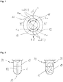
- Fig. 1 shows the measuring scheme used to define the angles.
- An axis c is shown that extends from a top end t to a bottom end b of a powder chamber (not shown).
- a first wall section 11 and a second wall section 12 extend along the axis c.
- the wall sections are only used by way of example to explain a measuring direction md.
- First angles ⁇ 11 are measured from the axis c to the wall section 11, so that the acute angle is obtained.
- second angles ⁇ 12 that are formed between the second wall section 12 and the axis c. If the measuring direction is directed from the top end t to the bottom end b, the angles are counted positive. If the measuring direction md is directed from the bottom end b to the top end t, the angles are counted negative. Positive angles reach from 0 ° to ⁇ 90 °, negative angles reach from 0 ° to > -90 °.
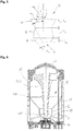
- Fig. 2 shows two working principles of air-polishing devices, in particular of powder chambers 10.
- the powder chambers 10 are filled, for example, with powder 1, such as sodium bicarbonate powder, which is steered up by pressurized air.
- the pressurized air gets into the powder chambers 10 via air inlets 20.
- An air/powder-mixture is transported via outlets 30, for example through a tube to a nozzle where water is added.
- a venturi tube 83 is located within the powder chamber 10.
- the air/powder-mixture is created by swirling only.
- Fig. 3 shows a powder chamber 10 that extends along an axis c from a top end t to a bottom end b.
- the powder chamber 10 comprises a first wall section 11 and a second wall section 12.
- the first wall section 11 forms a first angle ⁇ 11 with the axis c.
- the second wall section 12 forms a second angle ⁇ 12 with the axis c.
- the first angle is, according to one embodiment, at least 20 °, preferably at least about 27 °.
- the second angle is smaller, as can be seen from Figure 3 . This provides more space for the powder that is located within the powder chamber.
- the first wall section 11 has a length l 11 and the second wall section 12 has a length l 12 which form appropriate volumes.
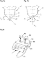
- Fig. 4 shows a powder chamber 10 similarly to that known from Figure 3 .
- the powder chamber 10 comprises also a third wall section 13.
- a second wall section 12 is basically parallel orientated with respect to an axis c forming a pit.
- a second angle ⁇ 12 is basically 0° and thus smaller as a first angle ⁇ 11 of the first wall section 11.
- a third angle ⁇ 13 of the third wall section 13 is bigger than the second angle ⁇ 12 of the second wall section 12.
- the wall sections 11, 12 and 13 extend along the axis c from a top end t to a bottom end b and have a length l 11 , l 12 or l 13 , forming/defining appropriate volumes.
- Figure 4 shows a "double cone"-design.
- the first and the third angles ⁇ 11 , ⁇ 13 are at least about 20 °, preferably at least about 25 ° or at least about 27 °. This means that an angulation of the cones is at least about 50 °, preferably at least about 55 °.
- Fig. 5 shows a further embodiment of a powder chamber 10 comprising three wall sections 11, 12, 13 extending along an axis c from a top end t to a bottom end b.
- the first wall section 11 forms a first angle ⁇ 11 with respect to the axis c.
- the first angle ⁇ 11 is bigger than 0 ° thus forming a first cone.
- a second angle ⁇ 12 of the second wall section 12 is smaller than the first angle ⁇ 11 .
- the second angle ⁇ 12 is negative whereby self-blockade can be prevented very effectively.
- a third angle ⁇ 13 formed by the third wall section 13 is bigger than the second angle ⁇ 12 .
- the third angle ⁇ 13 is again positive (forming a second cone), similar to the first angle ⁇ 11 whereby a very small third volume is formed which optimizes the emptying-behaviour and which reduces the residual powder left within the powder chamber 10.
- Fig. 6 shows a container 80 as it is used in air-polishing devices.
- the powder chamber 10 comprises a first wall section 11, a second wall section 12 and a third wall section 13.
- the powder chamber 10 extends along an axis c from a top end t to a bottom end b.
- the top end t of the powder chamber 10 comprises a sealing portion 40 which seals in particular the first wall section 11 with respect to the container 80.
- the bottom end b of the powder chamber 10 comprises an air inlet 20.
- the top end t of the powder chamber 10 is adapted to arrange an insert 82.
- the insert 82 comprises a venturi tube 83.
- An outlet 30 is adapted to bring/conduct an air/powder-mixture to an air polishing device (not shown).
- the walls of the third wall section 13 do not converge into an apex. Instead, a flat bottom plate 14 is formed which is adapted to avoid blocking of the air inlet 20 due to the powder which is in the powder chamber 10.
- Figures 7a and 7b deal with this aspect in a more detailed way.
- Fig. 7a shows a powder chamber 10, in particular a bottom end b and a third wall section 13.
- An air inlet 20 extends into the powder chamber 10, in particular into the volume formed by the third wall section 13.
- a distance l 22 which extends between the bottom end b and a nozzle 22 of the air inlet 20 lies preferably within a range of about 1 to 5 mm. This prevents the air inlet 20 or the nozzle 22, respectively, from plugging/blocking with powder.
- Fig. 7b shows a powder chamber 10, similar to the one shown in Fig. 7b .
- a diameter d 14 lies according to some embodiments within a range of about 3 to 25 mm, preferably within a range of about 4 to 20 mm, in particular within a range of about 10 mm.
- the bottom plate 14 avoids blocking/plugging of the air inlet 20 or the nozzle 22, respectively.
- the nozzle 22 extends also a little bit into the volume formed by a third wall section 13. This increases the effect of the bottom plate 14.
- FIG. 8 shows by way of example an air polishing device 90 comprising two containers 80 that are arranged at a basic device of the air polishing device 90.
- a flexible tube 92 is arranged at the basic device.
- the flexible tube 92 ends in a hand sample 94 that includes a nozzle 96.
- the container 80 can be easily removed if a (inserted) powder chamber is empty. Alternatively, only the powder chamber that is arranged within the container may be removed to insert a new (full) one.
Claims (12)
- Chambre de poudre (10) pour un dispositif de polissage par air (80), s'étendant depuis une extrémité supérieure (t) jusqu'à une extrémité inférieure (b) le long d'un axe (c),
ladite chambre de poudre (10) comprenant au moins deux sections de paroi (11 ; 12),
dans laquelle une première section de paroi (11) forme un premier angle (α11) par rapport à l'axe (c), et
dans laquelle une deuxième section de paroi (12) forme un deuxième angle (α12) par rapport à l'axe (c),
dans laquelle les angles (α11, α12) sont mesurés dans une direction de mesurage (md) depuis l'axe (c) jusqu'à la section de paroi appropriée (11 ; 12) de manière à obtenir des angles aigus,
dans laquelle la direction de mesurage (md) depuis l'extrémité supérieure (t) jusqu'à l'extrémité inférieure (b) est comptée de manière positive, et
dans laquelle la direction de mesurage (md) depuis l'extrémité inférieure (b) jusqu'à l'extrémité supérieure (t) est comptée de manière négative,
dans laquelle la deuxième section de paroi (12) est agencée en dessous de la première section de paroi (11), et
dans laquelle le deuxième angle (α12) est inférieur au premier angle (α11), et
dans laquelle la chambre de poudre (10) comprend une troisième section de paroi (13) qui forme un troisième angle (α13) par rapport à l'axe (c), et
dans laquelle le troisième angle (α13) est supérieur au deuxième angle (α12), et
dans laquelle la troisième section de paroi (13) est agencée en dessous de la deuxième section de paroi (12),
dans laquelle l'extrémité inférieure (b) comprend une entrée d'air (20),
dans laquelle une plaque de fond (14) est agencée au niveau de l'extrémité inférieure de la chambre de poudre (10) et/ou l'entrée d'air (20) s'étend jusque dans la chambre de poudre (10). - Chambre de poudre (10) selon la revendication 1,
dans laquelle la première section de paroi (11) est inclinée en direction de l'axe (c) formant un premier angle (α11) > 0. - Chambre de poudre (10) selon la revendication 1 ou 2,
dans laquelle le premier angle (α11) et/ou le troisième angle (α13) est au moins 15°, de préférence au moins 25°. - Chambre de poudre (10) selon l'une quelconque des revendications précédentes,
dans laquelle le deuxième angle (α12) est fondamentalement 0°. - Chambre de poudre (10) selon l'une quelconque des revendications 2 à 4,
dans laquelle un volume (v13) de la chambre de poudre (10), limité par la troisième section de paroi (13), est inférieur à 25 % d'un volume complet de la chambre de poudre (10). - Chambre de poudre (10) selon l'une quelconque des revendications précédentes,
dans laquelle une longueur (l12) de la deuxième section de paroi (12) est au moins d'environ 5 mm. - Chambre de poudre (10) selon la revendication 6,
dans laquelle un rapport entre la longueur (l12) de la deuxième section de paroi (12) et une longueur (l13) de la troisième section de paroi (13) est inférieur à 1. - Chambre de poudre (10) selon l'une quelconque des revendications 6 à 7,
dans laquelle un rapport entre une longueur (l11) de la première section de paroi (11) et la longueur (l12) de la deuxième section de paroi (12) est supérieur à 1. - Chambre de poudre (10) selon l'une quelconque des revendications précédentes,
dans laquelle la chambre de poudre (10) est à symétrie de révolution. - Chambre de poudre (10) selon l'une quelconque des revendications précédentes,
dans laquelle l'extrémité supérieure (t) comprend une portion d'étanchéité (40). - Chambre de poudre (10) selon l'une quelconque des revendications précédentes,
dans laquelle un tube de Venturi (83) est agencé à l'intérieur ou au niveau de la chambre de poudre (10). - Dispositif de polissage par air (90) comprenant une chambre de poudre (10) selon l'une quelconque des revendications 1 à 11.
Priority Applications (7)
| Application Number | Priority Date | Filing Date | Title |
|---|---|---|---|
| EP15186315.6A EP3146933B1 (fr) | 2015-09-22 | 2015-09-22 | Chambre de poudre pour un dispositif de polissage par air et dispositif de polissage par air |
| CN202111267746.5A CN114012611A (zh) | 2015-09-22 | 2016-07-04 | 用于空气抛光装置的粉末室和空气抛光装置 |
| JP2018513582A JP2018527105A (ja) | 2015-09-22 | 2016-07-04 | 空気研磨装置用粉末室及び空気研磨装置 |
| CN201680049651.7A CN107920867A (zh) | 2015-09-22 | 2016-07-04 | 用于空气抛光装置的粉末室和空气抛光装置 |
| US15/761,682 US20180360559A1 (en) | 2015-09-22 | 2016-07-04 | Powder chamber for an air-polishing device and air-polishing device |
| PCT/EP2016/065658 WO2017050451A1 (fr) | 2015-09-22 | 2016-07-04 | Chambre à poudre pour dispositif de polissage à l'air, et dispositif de polissage à l'air |
| JP2022109511A JP2022133419A (ja) | 2015-09-22 | 2022-07-07 | 空気研磨装置用粉末室及び空気研磨装置 |
Applications Claiming Priority (1)
| Application Number | Priority Date | Filing Date | Title |
|---|---|---|---|
| EP15186315.6A EP3146933B1 (fr) | 2015-09-22 | 2015-09-22 | Chambre de poudre pour un dispositif de polissage par air et dispositif de polissage par air |
Publications (2)
| Publication Number | Publication Date |
|---|---|
| EP3146933A1 EP3146933A1 (fr) | 2017-03-29 |
| EP3146933B1 true EP3146933B1 (fr) | 2019-11-20 |
Family
ID=54249305
Family Applications (1)
| Application Number | Title | Priority Date | Filing Date |
|---|---|---|---|
| EP15186315.6A Active EP3146933B1 (fr) | 2015-09-22 | 2015-09-22 | Chambre de poudre pour un dispositif de polissage par air et dispositif de polissage par air |
Country Status (5)
| Country | Link |
|---|---|
| US (1) | US20180360559A1 (fr) |
| EP (1) | EP3146933B1 (fr) |
| JP (2) | JP2018527105A (fr) |
| CN (2) | CN107920867A (fr) |
| WO (1) | WO2017050451A1 (fr) |
Families Citing this family (4)
| Publication number | Priority date | Publication date | Assignee | Title |
|---|---|---|---|---|
| USD825741S1 (en) | 2016-12-15 | 2018-08-14 | Water Pik, Inc. | Oral irrigator handle |
| AU2018236429B2 (en) | 2017-03-16 | 2023-02-02 | Water Pik, Inc. | Oral irrigator handle for use with oral agent |
| USD868243S1 (en) | 2018-03-16 | 2019-11-26 | Water Pik, Inc. | Oral irrigator tip |
| KR102565615B1 (ko) * | 2023-04-13 | 2023-08-10 | 최상진 | 임플란트 샌딩기 |
Family Cites Families (14)
| Publication number | Priority date | Publication date | Assignee | Title |
|---|---|---|---|---|
| SE359766B (fr) * | 1972-01-26 | 1973-09-10 | Atlas Copco Ab | |
| US3798841A (en) * | 1972-06-13 | 1974-03-26 | A Eppler | Pressure feed for sand blast abrasive |
| DE3212207A1 (de) * | 1982-04-01 | 1983-10-06 | Siemens Ag | Geraet zur oberflaechenbehandlung von zaehnen, insebondere zum entfernen von zahnbelag |
| US4494932A (en) * | 1983-02-18 | 1985-01-22 | Cooper Lasersonics, Inc. | Dental cleaning apparatus and method |
| US4487582A (en) | 1983-02-18 | 1984-12-11 | Cooper Lasersonics, Inc. | Dental cleaning system |
| DE4332226A1 (de) * | 1993-09-22 | 1995-03-23 | Wassermann Dental Maschinen Gm | Dentaltechnisches Sandstrahlgerät |
| US6074135A (en) * | 1996-09-25 | 2000-06-13 | Innovative Technologies, Inc. | Coating or ablation applicator with debris recovery attachment |
| JP4171539B2 (ja) * | 1998-06-09 | 2008-10-22 | 株式会社不二製作所 | 直圧式連続研磨材供給・噴射方法及び装置 |
| GB9825110D0 (en) | 1998-11-16 | 1999-01-13 | Medivance Instr Limited | Pneumatic device |
| SE0400282D0 (sv) * | 2004-02-09 | 2004-02-09 | Microdrug Ag | Machine for volumetric filing of powders |
| EP2742899B1 (fr) * | 2004-10-14 | 2022-08-10 | DENTSPLY SIRONA Inc. | Systeme prophylactique de polissage pneumatique |
| EP1972295B9 (fr) | 2007-03-19 | 2021-07-14 | Ferton Holding S.A. | Conteneur de poudre pour un pulvérisateur de poudre |
| DE102010020691B4 (de) * | 2010-05-17 | 2014-09-04 | Pieper Innovationsgesellschaft Mbh | Verfahren und Vorrichtung zum Fördern und Dosieren von Schüttgut beim Vakuumsaugstrahlen |
| CN104416470A (zh) * | 2013-09-05 | 2015-03-18 | 陈均 | 一种喷砂机 |
-
2015
- 2015-09-22 EP EP15186315.6A patent/EP3146933B1/fr active Active
-
2016
- 2016-07-04 CN CN201680049651.7A patent/CN107920867A/zh active Pending
- 2016-07-04 WO PCT/EP2016/065658 patent/WO2017050451A1/fr active Application Filing
- 2016-07-04 CN CN202111267746.5A patent/CN114012611A/zh active Pending
- 2016-07-04 JP JP2018513582A patent/JP2018527105A/ja active Pending
- 2016-07-04 US US15/761,682 patent/US20180360559A1/en active Pending
-
2022
- 2022-07-07 JP JP2022109511A patent/JP2022133419A/ja active Pending
Non-Patent Citations (1)
| Title |
|---|
| None * |
Also Published As
| Publication number | Publication date |
|---|---|
| CN114012611A (zh) | 2022-02-08 |
| WO2017050451A1 (fr) | 2017-03-30 |
| JP2022133419A (ja) | 2022-09-13 |
| CN107920867A (zh) | 2018-04-17 |
| EP3146933A1 (fr) | 2017-03-29 |
| US20180360559A1 (en) | 2018-12-20 |
| JP2018527105A (ja) | 2018-09-20 |
Similar Documents
| Publication | Publication Date | Title |
|---|---|---|
| EP3146933B1 (fr) | Chambre de poudre pour un dispositif de polissage par air et dispositif de polissage par air | |
| JP5039042B2 (ja) | 所要量の粉体状またはペースト状の材料物質を供給するためのディスペンサ・デバイス | |
| US7401973B1 (en) | Dust-free low pressure mixing system | |
| US20030224704A1 (en) | Rotary media valve | |
| KR19980701240A (ko) | 주입형 입상 재료, 특히 블라스팅 연마제의 투입용 장치(Device for the Dosing of Granular, Pourable Material, in Particular Blasting Shots) | |
| DE19652860C2 (de) | Vorrichtung zum Fördern von Tonermaterial aus einem Vorratsbehälter | |
| KR100886581B1 (ko) | 미분된 미립 물질의 밀도를 증가시키기 위한 장치 및 방법 | |
| JP2008529904A (ja) | 少なくとも1種の粒状材料を容器内へ分配する装置、充填装置、およびそのような装置を用いた充填方法 | |
| US7618182B1 (en) | Dust-free low pressure mixing system with jet ring adapter | |
| JP7462608B2 (ja) | 粉体供給方法及び熱可塑性樹脂組成物の製造方法 | |
| CN109311062B (zh) | 用于将塑料颗粒和液体共同地输入到净化装置中的设备和方法 | |
| JP2009247999A (ja) | 混合装置 | |
| US8727182B2 (en) | Feeder for particle delivery | |
| US20140233343A1 (en) | Tools for precisely, consistently, and reliably propelling a wide range of particulate media | |
| US20170029218A1 (en) | Dosing method and dosing device for particles of bulk material | |
| US8297541B2 (en) | Dust reduction in delivery of particulate commodities | |
| JP5665080B2 (ja) | 粉粒体充填装置 | |
| US8172645B2 (en) | Dosing device | |
| CN106241100B (zh) | 一种流化防堵卸料阀 | |
| CN210285390U (zh) | 料仓总成及粉料输送系统 | |
| RU2083459C1 (ru) | Пневмотранспортная установка для вакуумной перегрузки порошкообразного материала из тары в емкости с малой загрузочной горловиной | |
| CN108529142A (zh) | 一种用于输送微细粉体的送粉器 | |
| RU2309884C1 (ru) | Пневмотранспортная установка для раздачи сыпучих материалов | |
| CN116438039A (zh) | 用于从co2雪制备co2颗粒的设备和方法以及清洁器具 | |
| JP5118857B2 (ja) | 粉粒体供給装置 |
Legal Events
| Date | Code | Title | Description |
|---|---|---|---|
| PUAI | Public reference made under article 153(3) epc to a published international application that has entered the european phase |
Free format text: ORIGINAL CODE: 0009012 |
|
| STAA | Information on the status of an ep patent application or granted ep patent |
Free format text: STATUS: THE APPLICATION HAS BEEN PUBLISHED |
|
| AK | Designated contracting states |
Kind code of ref document: A1 Designated state(s): AL AT BE BG CH CY CZ DE DK EE ES FI FR GB GR HR HU IE IS IT LI LT LU LV MC MK MT NL NO PL PT RO RS SE SI SK SM TR |
|
| AX | Request for extension of the european patent |
Extension state: BA ME |
|
| STAA | Information on the status of an ep patent application or granted ep patent |
Free format text: STATUS: REQUEST FOR EXAMINATION WAS MADE |
|
| 17P | Request for examination filed |
Effective date: 20170509 |
|
| RBV | Designated contracting states (corrected) |
Designated state(s): AL AT BE BG CH CY CZ DE DK EE ES FI FR GB GR HR HU IE IS IT LI LT LU LV MC MK MT NL NO PL PT RO RS SE SI SK SM TR |
|
| STAA | Information on the status of an ep patent application or granted ep patent |
Free format text: STATUS: EXAMINATION IS IN PROGRESS |
|
| 17Q | First examination report despatched |
Effective date: 20190204 |
|
| GRAP | Despatch of communication of intention to grant a patent |
Free format text: ORIGINAL CODE: EPIDOSNIGR1 |
|
| STAA | Information on the status of an ep patent application or granted ep patent |
Free format text: STATUS: GRANT OF PATENT IS INTENDED |
|
| INTG | Intention to grant announced |
Effective date: 20190716 |
|
| GRAS | Grant fee paid |
Free format text: ORIGINAL CODE: EPIDOSNIGR3 |
|
| GRAA | (expected) grant |
Free format text: ORIGINAL CODE: 0009210 |
|
| STAA | Information on the status of an ep patent application or granted ep patent |
Free format text: STATUS: THE PATENT HAS BEEN GRANTED |
|
| AK | Designated contracting states |
Kind code of ref document: B1 Designated state(s): AL AT BE BG CH CY CZ DE DK EE ES FI FR GB GR HR HU IE IS IT LI LT LU LV MC MK MT NL NO PL PT RO RS SE SI SK SM TR |
|
| REG | Reference to a national code |
Ref country code: GB Ref legal event code: FG4D |
|
| REG | Reference to a national code |
Ref country code: CH Ref legal event code: EP |
|
| REG | Reference to a national code |
Ref country code: IE Ref legal event code: FG4D |
|
| REG | Reference to a national code |
Ref country code: DE Ref legal event code: R096 Ref document number: 602015041955 Country of ref document: DE |
|
| REG | Reference to a national code |
Ref country code: AT Ref legal event code: REF Ref document number: 1203301 Country of ref document: AT Kind code of ref document: T Effective date: 20191215 |
|
| REG | Reference to a national code |
Ref country code: CH Ref legal event code: NV Representative=s name: HEPP WENGER RYFFEL AG, CH |
|
| REG | Reference to a national code |
Ref country code: NL Ref legal event code: FP |
|
| REG | Reference to a national code |
Ref country code: LT Ref legal event code: MG4D |
|
| PG25 | Lapsed in a contracting state [announced via postgrant information from national office to epo] |
Ref country code: NO Free format text: LAPSE BECAUSE OF FAILURE TO SUBMIT A TRANSLATION OF THE DESCRIPTION OR TO PAY THE FEE WITHIN THE PRESCRIBED TIME-LIMIT Effective date: 20200220 Ref country code: LT Free format text: LAPSE BECAUSE OF FAILURE TO SUBMIT A TRANSLATION OF THE DESCRIPTION OR TO PAY THE FEE WITHIN THE PRESCRIBED TIME-LIMIT Effective date: 20191120 Ref country code: GR Free format text: LAPSE BECAUSE OF FAILURE TO SUBMIT A TRANSLATION OF THE DESCRIPTION OR TO PAY THE FEE WITHIN THE PRESCRIBED TIME-LIMIT Effective date: 20200221 Ref country code: LV Free format text: LAPSE BECAUSE OF FAILURE TO SUBMIT A TRANSLATION OF THE DESCRIPTION OR TO PAY THE FEE WITHIN THE PRESCRIBED TIME-LIMIT Effective date: 20191120 Ref country code: FI Free format text: LAPSE BECAUSE OF FAILURE TO SUBMIT A TRANSLATION OF THE DESCRIPTION OR TO PAY THE FEE WITHIN THE PRESCRIBED TIME-LIMIT Effective date: 20191120 Ref country code: BG Free format text: LAPSE BECAUSE OF FAILURE TO SUBMIT A TRANSLATION OF THE DESCRIPTION OR TO PAY THE FEE WITHIN THE PRESCRIBED TIME-LIMIT Effective date: 20200220 Ref country code: SE Free format text: LAPSE BECAUSE OF FAILURE TO SUBMIT A TRANSLATION OF THE DESCRIPTION OR TO PAY THE FEE WITHIN THE PRESCRIBED TIME-LIMIT Effective date: 20191120 |
|
| PG25 | Lapsed in a contracting state [announced via postgrant information from national office to epo] |
Ref country code: RS Free format text: LAPSE BECAUSE OF FAILURE TO SUBMIT A TRANSLATION OF THE DESCRIPTION OR TO PAY THE FEE WITHIN THE PRESCRIBED TIME-LIMIT Effective date: 20191120 Ref country code: IS Free format text: LAPSE BECAUSE OF FAILURE TO SUBMIT A TRANSLATION OF THE DESCRIPTION OR TO PAY THE FEE WITHIN THE PRESCRIBED TIME-LIMIT Effective date: 20200320 Ref country code: HR Free format text: LAPSE BECAUSE OF FAILURE TO SUBMIT A TRANSLATION OF THE DESCRIPTION OR TO PAY THE FEE WITHIN THE PRESCRIBED TIME-LIMIT Effective date: 20191120 |
|
| PG25 | Lapsed in a contracting state [announced via postgrant information from national office to epo] |
Ref country code: AL Free format text: LAPSE BECAUSE OF FAILURE TO SUBMIT A TRANSLATION OF THE DESCRIPTION OR TO PAY THE FEE WITHIN THE PRESCRIBED TIME-LIMIT Effective date: 20191120 |
|
| PG25 | Lapsed in a contracting state [announced via postgrant information from national office to epo] |
Ref country code: PT Free format text: LAPSE BECAUSE OF FAILURE TO SUBMIT A TRANSLATION OF THE DESCRIPTION OR TO PAY THE FEE WITHIN THE PRESCRIBED TIME-LIMIT Effective date: 20200412 Ref country code: ES Free format text: LAPSE BECAUSE OF FAILURE TO SUBMIT A TRANSLATION OF THE DESCRIPTION OR TO PAY THE FEE WITHIN THE PRESCRIBED TIME-LIMIT Effective date: 20191120 Ref country code: CZ Free format text: LAPSE BECAUSE OF FAILURE TO SUBMIT A TRANSLATION OF THE DESCRIPTION OR TO PAY THE FEE WITHIN THE PRESCRIBED TIME-LIMIT Effective date: 20191120 Ref country code: DK Free format text: LAPSE BECAUSE OF FAILURE TO SUBMIT A TRANSLATION OF THE DESCRIPTION OR TO PAY THE FEE WITHIN THE PRESCRIBED TIME-LIMIT Effective date: 20191120 Ref country code: RO Free format text: LAPSE BECAUSE OF FAILURE TO SUBMIT A TRANSLATION OF THE DESCRIPTION OR TO PAY THE FEE WITHIN THE PRESCRIBED TIME-LIMIT Effective date: 20191120 Ref country code: EE Free format text: LAPSE BECAUSE OF FAILURE TO SUBMIT A TRANSLATION OF THE DESCRIPTION OR TO PAY THE FEE WITHIN THE PRESCRIBED TIME-LIMIT Effective date: 20191120 |
|
| REG | Reference to a national code |
Ref country code: DE Ref legal event code: R097 Ref document number: 602015041955 Country of ref document: DE |
|
| PG25 | Lapsed in a contracting state [announced via postgrant information from national office to epo] |
Ref country code: SM Free format text: LAPSE BECAUSE OF FAILURE TO SUBMIT A TRANSLATION OF THE DESCRIPTION OR TO PAY THE FEE WITHIN THE PRESCRIBED TIME-LIMIT Effective date: 20191120 Ref country code: SK Free format text: LAPSE BECAUSE OF FAILURE TO SUBMIT A TRANSLATION OF THE DESCRIPTION OR TO PAY THE FEE WITHIN THE PRESCRIBED TIME-LIMIT Effective date: 20191120 |
|
| PLBE | No opposition filed within time limit |
Free format text: ORIGINAL CODE: 0009261 |
|
| STAA | Information on the status of an ep patent application or granted ep patent |
Free format text: STATUS: NO OPPOSITION FILED WITHIN TIME LIMIT |
|
| 26N | No opposition filed |
Effective date: 20200821 |
|
| PG25 | Lapsed in a contracting state [announced via postgrant information from national office to epo] |
Ref country code: PL Free format text: LAPSE BECAUSE OF FAILURE TO SUBMIT A TRANSLATION OF THE DESCRIPTION OR TO PAY THE FEE WITHIN THE PRESCRIBED TIME-LIMIT Effective date: 20191120 Ref country code: SI Free format text: LAPSE BECAUSE OF FAILURE TO SUBMIT A TRANSLATION OF THE DESCRIPTION OR TO PAY THE FEE WITHIN THE PRESCRIBED TIME-LIMIT Effective date: 20191120 |
|
| PG25 | Lapsed in a contracting state [announced via postgrant information from national office to epo] |
Ref country code: MC Free format text: LAPSE BECAUSE OF FAILURE TO SUBMIT A TRANSLATION OF THE DESCRIPTION OR TO PAY THE FEE WITHIN THE PRESCRIBED TIME-LIMIT Effective date: 20191120 |
|
| PG25 | Lapsed in a contracting state [announced via postgrant information from national office to epo] |
Ref country code: LU Free format text: LAPSE BECAUSE OF NON-PAYMENT OF DUE FEES Effective date: 20200922 |
|
| PG25 | Lapsed in a contracting state [announced via postgrant information from national office to epo] |
Ref country code: TR Free format text: LAPSE BECAUSE OF FAILURE TO SUBMIT A TRANSLATION OF THE DESCRIPTION OR TO PAY THE FEE WITHIN THE PRESCRIBED TIME-LIMIT Effective date: 20191120 Ref country code: MT Free format text: LAPSE BECAUSE OF FAILURE TO SUBMIT A TRANSLATION OF THE DESCRIPTION OR TO PAY THE FEE WITHIN THE PRESCRIBED TIME-LIMIT Effective date: 20191120 Ref country code: CY Free format text: LAPSE BECAUSE OF FAILURE TO SUBMIT A TRANSLATION OF THE DESCRIPTION OR TO PAY THE FEE WITHIN THE PRESCRIBED TIME-LIMIT Effective date: 20191120 |
|
| PG25 | Lapsed in a contracting state [announced via postgrant information from national office to epo] |
Ref country code: MK Free format text: LAPSE BECAUSE OF FAILURE TO SUBMIT A TRANSLATION OF THE DESCRIPTION OR TO PAY THE FEE WITHIN THE PRESCRIBED TIME-LIMIT Effective date: 20191120 |
|
| P01 | Opt-out of the competence of the unified patent court (upc) registered |
Effective date: 20230530 |
|
| PGFP | Annual fee paid to national office [announced via postgrant information from national office to epo] |
Ref country code: NL Payment date: 20230920 Year of fee payment: 9 Ref country code: IE Payment date: 20230918 Year of fee payment: 9 Ref country code: GB Payment date: 20230921 Year of fee payment: 9 Ref country code: AT Payment date: 20230915 Year of fee payment: 9 |
|
| PGFP | Annual fee paid to national office [announced via postgrant information from national office to epo] |
Ref country code: FR Payment date: 20230919 Year of fee payment: 9 Ref country code: DE Payment date: 20230724 Year of fee payment: 9 Ref country code: BE Payment date: 20230918 Year of fee payment: 9 |
|
| PGFP | Annual fee paid to national office [announced via postgrant information from national office to epo] |
Ref country code: IT Payment date: 20230929 Year of fee payment: 9 Ref country code: CH Payment date: 20231001 Year of fee payment: 9 |