EP3146933B1 - Powder chamber for an air-polishing device and air-polishing device - Google Patents
Powder chamber for an air-polishing device and air-polishing device Download PDFInfo
- Publication number
- EP3146933B1 EP3146933B1 EP15186315.6A EP15186315A EP3146933B1 EP 3146933 B1 EP3146933 B1 EP 3146933B1 EP 15186315 A EP15186315 A EP 15186315A EP 3146933 B1 EP3146933 B1 EP 3146933B1
- Authority
- EP
- European Patent Office
- Prior art keywords
- powder chamber
- wall section
- powder
- angle
- air
- Prior art date
- Legal status (The legal status is an assumption and is not a legal conclusion. Google has not performed a legal analysis and makes no representation as to the accuracy of the status listed.)
- Active
Links
- 239000000843 powder Substances 0.000 title claims description 173
- 238000005498 polishing Methods 0.000 title claims description 27
- 238000007789 sealing Methods 0.000 claims description 7
- 230000001154 acute effect Effects 0.000 claims description 3
- 238000000034 method Methods 0.000 description 8
- 239000000203 mixture Substances 0.000 description 8
- 239000002245 particle Substances 0.000 description 7
- 230000000903 blocking effect Effects 0.000 description 6
- VTYYLEPIZMXCLO-UHFFFAOYSA-L Calcium carbonate Chemical compound [Ca+2].[O-]C([O-])=O VTYYLEPIZMXCLO-UHFFFAOYSA-L 0.000 description 4
- DHMQDGOQFOQNFH-UHFFFAOYSA-N Glycine Chemical compound NCC(O)=O DHMQDGOQFOQNFH-UHFFFAOYSA-N 0.000 description 4
- 230000000694 effects Effects 0.000 description 4
- 238000012856 packing Methods 0.000 description 4
- 230000008569 process Effects 0.000 description 4
- 230000008901 benefit Effects 0.000 description 3
- 238000005422 blasting Methods 0.000 description 3
- 239000000463 material Substances 0.000 description 3
- XLYOFNOQVPJJNP-UHFFFAOYSA-N water Substances O XLYOFNOQVPJJNP-UHFFFAOYSA-N 0.000 description 3
- UNXHWFMMPAWVPI-UHFFFAOYSA-N Erythritol Natural products OCC(O)C(O)CO UNXHWFMMPAWVPI-UHFFFAOYSA-N 0.000 description 2
- 239000004386 Erythritol Substances 0.000 description 2
- 239000004471 Glycine Substances 0.000 description 2
- UIIMBOGNXHQVGW-UHFFFAOYSA-M Sodium bicarbonate Chemical compound [Na+].OC([O-])=O UIIMBOGNXHQVGW-UHFFFAOYSA-M 0.000 description 2
- UIIMBOGNXHQVGW-DEQYMQKBSA-M Sodium bicarbonate-14C Chemical compound [Na+].O[14C]([O-])=O UIIMBOGNXHQVGW-DEQYMQKBSA-M 0.000 description 2
- 229910000019 calcium carbonate Inorganic materials 0.000 description 2
- 230000008859 change Effects 0.000 description 2
- 239000011248 coating agent Substances 0.000 description 2
- 238000005516 engineering process Methods 0.000 description 2
- UNXHWFMMPAWVPI-ZXZARUISSA-N erythritol Chemical compound OC[C@H](O)[C@H](O)CO UNXHWFMMPAWVPI-ZXZARUISSA-N 0.000 description 2
- 229940009714 erythritol Drugs 0.000 description 2
- 235000019414 erythritol Nutrition 0.000 description 2
- 239000000758 substrate Substances 0.000 description 2
- -1 welding flux Substances 0.000 description 2
- 239000013590 bulk material Substances 0.000 description 1
- 239000003795 chemical substances by application Substances 0.000 description 1
- 238000000576 coating method Methods 0.000 description 1
- 230000001419 dependent effect Effects 0.000 description 1
- 230000004907 flux Effects 0.000 description 1
- 230000001788 irregular Effects 0.000 description 1
- 229920001223 polyethylene glycol Polymers 0.000 description 1
- 238000011321 prophylaxis Methods 0.000 description 1
- 239000004576 sand Substances 0.000 description 1
- 238000005488 sandblasting Methods 0.000 description 1
- 238000007873 sieving Methods 0.000 description 1
- 229910000030 sodium bicarbonate Inorganic materials 0.000 description 1
- 235000017557 sodium bicarbonate Nutrition 0.000 description 1
- 150000005846 sugar alcohols Chemical class 0.000 description 1
- 230000032258 transport Effects 0.000 description 1
- 238000011282 treatment Methods 0.000 description 1
- 238000009827 uniform distribution Methods 0.000 description 1
- 238000003466 welding Methods 0.000 description 1
Images

Classifications
-
- A—HUMAN NECESSITIES
- A61—MEDICAL OR VETERINARY SCIENCE; HYGIENE
- A61C—DENTISTRY; APPARATUS OR METHODS FOR ORAL OR DENTAL HYGIENE
- A61C3/00—Dental tools or instruments
- A61C3/02—Tooth drilling or cutting instruments; Instruments acting like a sandblast machine
- A61C3/025—Instruments acting like a sandblast machine, e.g. for cleaning, polishing or cutting teeth
-
- B—PERFORMING OPERATIONS; TRANSPORTING
- B24—GRINDING; POLISHING
- B24C—ABRASIVE OR RELATED BLASTING WITH PARTICULATE MATERIAL
- B24C11/00—Selection of abrasive materials or additives for abrasive blasts
- B24C11/005—Selection of abrasive materials or additives for abrasive blasts of additives, e.g. anti-corrosive or disinfecting agents in solid, liquid or gaseous form
-
- B—PERFORMING OPERATIONS; TRANSPORTING
- B24—GRINDING; POLISHING
- B24C—ABRASIVE OR RELATED BLASTING WITH PARTICULATE MATERIAL
- B24C7/00—Equipment for feeding abrasive material; Controlling the flowability, constitution, or other physical characteristics of abrasive blasts
- B24C7/0046—Equipment for feeding abrasive material; Controlling the flowability, constitution, or other physical characteristics of abrasive blasts the abrasive material being fed in a gaseous carrier
- B24C7/0053—Equipment for feeding abrasive material; Controlling the flowability, constitution, or other physical characteristics of abrasive blasts the abrasive material being fed in a gaseous carrier with control of feed parameters, e.g. feed rate of abrasive material or carrier
-
- B—PERFORMING OPERATIONS; TRANSPORTING
- B24—GRINDING; POLISHING
- B24C—ABRASIVE OR RELATED BLASTING WITH PARTICULATE MATERIAL
- B24C7/00—Equipment for feeding abrasive material; Controlling the flowability, constitution, or other physical characteristics of abrasive blasts
- B24C7/0046—Equipment for feeding abrasive material; Controlling the flowability, constitution, or other physical characteristics of abrasive blasts the abrasive material being fed in a gaseous carrier
- B24C7/0069—Equipment for feeding abrasive material; Controlling the flowability, constitution, or other physical characteristics of abrasive blasts the abrasive material being fed in a gaseous carrier with means for preventing clogging of the equipment or for preventing abrasive entering the airway
Description
- This invention relates to a powder chamber for an air-polishing device and to an air-polishing device.
- Air-polishing devices, in particular air-polishing devices that comprise powder chambers, are used in the sand blasting technology, e. g. in the dental field. In this technology a powder is used for the dental prophylaxis, wherein the powder is a low abrasive powder, as for example sodium bicarbonate, calcium carbonate, glycine or erythritol. To avoid damaging of the teeth, the powder has a small grain size ranging from about 100 µm down to about 13 µm on average. There are mainly two ways to take out the powder from the powder chamber: one is by injecting air from the top of the powder chamber and the other is by injecting the air from the bottom of the powder chamber.
- The second method delivers the most accurate powder flow rate and enables the best treatment. Nevertheless, the system presents different issues: the powder needs to flow up to a suction nozzle, but it is well known that the flow of small powders (< 100 µm) is difficult to control. Additionally, the complete emptying of the powder chamber is not achieved all the time and the powder flow shows irregularities during emptying of the powder chamber.
-
EP 2 193 758 B1 uses a powder chamber that has two inclined planes. Such system may have a varying flow rate and a relatively high residue inside the powder chamber because the powder may get stuck in the chamber due to self-blockade.EP 0 119 021 B2 uses a simple cone with two inclinations. However, to make the system work properly, a powder has to be chosen which consists of relatively large particles, approximately 100 µm. Another solution to overcome the problem is to change completely the powder delivery process by using some vibrating system like described inGB 2 347 372 A -
GB 1,394,483 -
US 3,798,841 refers to an arrangement which permits accurate regulation of grit of varying sizes in a continuous sand blast operation which replaces the batch feed systems. -
US 6,074,135 refers to an environmentally compliant triboelectric applicator and process for coating or ablating a substrate and for retrieving excess or ejected material from the substrate. -
WO 2012/019576 A1 refers to a method for conveying and metering bulk material, for example blasting agent, welding flux, coating agent, or the like, during the processing. - Therefore, it is an object of the present invention to provide a powder chamber for an air-polishing device and an air-polishing device that enables a very constant flow rate, good flow control and which provides an improved emptying-behaviour with no or a low residue of powder within the powder chamber.
- This object is achieved by means of a powder chamber for an air-polishing device according to
claim 1 and by an air-polishing device according toclaim 12. Additional advantages and features of preferred embodiments of the current invention are defined in the dependent claims. - According to the invention, a powder chamber for an air-polishing device extends from a top end to a bottom end along an axis, said powder chamber comprising at least two wall sections that extend along the axis, wherein the first wall section forms a first angle with respect to the axis, and wherein a second wall section forms a second angle with respect to the axis, wherein the angles are measured in a measuring direction from the axis to the appropriate wall section in such a manner so that the acute angles are obtained, wherein the measuring direction from the top end to the bottom end is counted positive, and wherein the measuring direction from the bottom end to the top end is counted negative, wherein the second wall section is arranged below/adjacent to the first wall section, and wherein the second angle is smaller than the first angle.
- According to one embodiment, the powder chamber extends from the top end to the bottom end along the axis, said powder chamber comprising the at least two wall sections, wherein the second wall section is arranged below the first wall section, wherein the first wall section is tapered with respect to the axis, and wherein the second wall section comprises a maximum cross section area that is at least as big as a minimum cross section of the first wall section.
- The powder chamber may for example be filled with low abrasive powder, such as sodium bicarbonate, calcium carbonate, glycine or an alditol like erythritol, which is steered up by pressurized air to form an air/powder-mixture. For this purpose, the powder chamber comprises for example an air inlet. According to one embodiment, the air/powder-mixture is transported via an outlet to an air polishing device that is adapted to process the air/powder-mixture, possibly added to a jet of water etc.
- According to one embodiment, air and powder is mixed by a combination of carburetor technique and swirling. In this case, a venturi tube is arranged/located within the powder chamber. An opening/inlet of the venturi tube is located near to the inlet of the powder chamber. An (pressurized) air stream that is directed from the inlet of the powder chamber to the opening/inlet of the venturi tube carries or transports powder that is located between or around the aforementioned inlets. In other words, powder is sucked into the venturi tube. A grain size of the powder is preferably smaller than about 100 µm on average, for example within a range of about 5-50 µm, expediently about 10-40 µm.
- Typically, the powder is ground and sieved to achieve a desired grain or particle size. The sieving process allows for example to choose particles that are smaller or bigger than a desired value (after graining). This means that "on average" does not inevitably mean a uniform distribution of the grain size. Instead, it is possible to sort out particles that are for example smaller than 5 µm or bigger than 70 µm or that are smaller than 10 µm and bigger than 40 µm. According to one embodiment, for example particles are sorted out (after graining) that are bigger than about 35 µm. This does not inevitably mean that most of the particles have a grain size of 35 µm.
- As already mentioned, such fine powders do not fall well. Thus, emptying of powder chambers, as known from the prior art, is not good and the powder flow shows irregularities during emptying. This is because, due to the suction, the powder level falls down from the middle of the powder chamber until creating some air ways resulting in powder flow rate change. In order to minimize this effect, one solution is to create a cone towards a bottom end of the powder chamber. However, there is the issue that this cone leads to powder packing during the powder flow towards the bottom of the powder chamber, blocking the functioning of the chamber (so called self-blockade). This packing is due to the small size of the powder and the geometry of the (single) cone.
- Preferably, the powder chamber according to the invention breaks down the tendency of the powder to be packed during falling down along a direction of gravitation which means from the top end to the bottom end of the powder chamber. This is achieved by the design of the second wall section that is arranged below the first wall section and which has an angle that is smaller than that of the first wall section (hence, the second wall section is more "in parallel" to the vertical than the first wall section). Thus, more space is provided for the powder which prevents or minimizes the packing-effect.
- To define the angles, the measuring direction has to be considered. If the measuring direction is directed from the top end to the bottom end, the angles are counted positive and vice versa. Positive angles reach from 0 ° to < 90 °, negative angles reach from 0 ° to > -90 °. An angle of +/- 90 ° would mean that the appropriate wall section does no longer "extend" along the axis. Therefore, the angles are smaller/bigger than +/- 90 °. An angle of +/- 0 ° means that the appropriate wall section is orientated parallel with respect to the axis. Thus, by way of example and to explain the measuring scheme, a first angle may be for example 12 °, wherein a second angle is 0° or -14°. "0" is "smaller" than "12". "-14" is "smaller" than "12", just as well.
- According to present invention the powder chamber comprises a third wall section that forms a third angle with respect to the axis, wherein the third angle is bigger than the second angle and wherein the third wall section is arranged below the second wall section. Thus, the third wall section of the powder chamber, respectively, is (again) - like the first wall section - tapered with respect to the axis.
- In other words, the first wall section or the "first volume" of the powder chamber is characterized by a cross-section area diminution up to 60 %, preferably 75 %, with respect to an inlet cross-section area which forms the opening of the powder chamber, wherein the diminution is at least as big as in the case of a cone/funnel-shaped chamber with a wall angle of 20 °, maximum 70 °.
- The second wall section or the "second volume" of the powder chamber has a cross-section area which can increase or diminish, wherein an increase lies within a range up to 50 %, preferably up to 30 %, and wherein a diminution lies within a range up to 10 %, wherein an average cross-section diminution is at least as big as in the case of a cone/funnel-shaped chamber with a wall angle of 20 °. The cross-section increase may be arbitrary. However, according to a preferred embodiment, the cross-section area of the second wall section stays basically constant.
- The bottom end of the third wall section or the bottom end of the powder chamber ("third volume"), respectively, is characterized by a cross-section diminution up to 7 %, preferably up to 5 % or even less, compared to the inlet cross-section area (cf. to the bottom plate, described hereinafter), wherein an average cross-section diminution is at least as big as in the case of a cone/funnel-shaped chamber with a wall angle of 20 °, maximum 70 °.
- The design of the third wall section leads to a very small volume of the powder chamber at its bottom end. If a venturi tube is located within the powder chamber, the small volume of the powder chamber around the venturi suction system leads to a constant environment of the venturi system during the complete emptying of the powder chamber which enables very constant flow rates.
- A further advantage is that, since the bottom volume of the powder chamber, in other words the suction volume or the third volume (formed by the third wall section) is very small, the residual powder left within the powder chamber becomes very low.
- It has to be mentioned that the powder chamber cannot only be used with venturi systems that are located in the middle of the powder chamber, as for example known from centro-symetric powder chambers. The powder chamber may be also used for a sided powder chamber where the venturi tube stays at a side of the powder chamber. The principle stays the same.
- According to one embodiment, the first wall section may be orientated basically parallel with respect to the axis.
- According to a preferred embodiment, the first wall section is inclined towards the axis forming a first angle that is bigger than 0. Thus, the first wall section forms a first cone or pit that is tapered with the respect to the axis. Cones or pits are known from the prior art, as already mentioned. However, along the direction of gravitation, the powder chamber comprises the second wall section, wherein the second wall section forms a second angle with respect to the axis that is smaller than the first angle formed by the first wall section. This avoids packing of the powder and enables a very constant flow rate.
- According to another embodiment, the first angle and/or the third angle is at least about 20°, preferably at least about 27°. The second angle is basically 0°. This means, that the second wall section is basically orientated parallel with respect to the axis, forming a kind of pit. Thus, the powder chamber is designed as "double cone", wherein the two cones are connected by the second wall section that is designed as pit. The first cone, formed by the first wall section, is tapered from the top end to the bottom end and has, according to one embodiment, an angulation that is bigger than about 50 °, preferably bigger than about 55 °. The same applies to the second cone which is formed by the third wall section. The angulation of the second cone helps to reduce the amount of residual powder.
- As the powder chamber comprises different wall sections, these different wall sections define different volumes. According to one embodiment, a volume of the powder chamber, limited by the third wall section, is less than 25 % of a complete volume of the powder chamber. As already mentioned before, the residual powder left within the powder chamber becomes very small.
- According to another embodiment, the powder chamber comprises a bottom plate, which is basically flat, according to a preferred embodiment. The bottom plate avoids blocking/plugging of an air inlet or a nozzle, respectively, which is arranged at the bottom end of the powder chamber according to the present invention. A diameter of the bottom plate lies, according to some embodiments, within a range of about 3 to 25 mm, preferably within a range of about 4 to 20 mm, in particular within a range of about 10 mm. Of course, if the powder chamber is not rotation-symmetric, the aforementioned values are transferable also to a, for example, rectangular or quadratic bottom plate.
- According to the present invention, the air inlet or nozzle extends into the powder chamber, in particular into the volume formed by the third wall section. This design enables a similar effect as the aforementioned bottom plate. A distance which extends between the bottom end of the powder chamber and the nozzle lies preferably within a range of about 1 to 5 mm. According to a specific embodiment, a bottom plate can be combined with an air inlet or nozzle that extends into the powder chamber. Alternatively, the air inlet or nozzle does not extend into the powder chamber, thus the aforementioned distance may be also 0.
- According to another embodiment, a length of the second wall section is at least about 5 mm. A ratio between a length of the first wall section and the length of the second wall section lies for example within a range of about 10-0,1, preferably within a range of about 5-0,5.
- According to another embodiment, a ratio between the length of the second wall section and a length of the third wall section is less than 1.
- In another embodiment, the ratio lies within a range of about 10-0,1, for example within a range of about 5-0,5. This design provides a small third volume, wherein enough space is provided by the second volume to prevent the powder from packing.
- According to another embodiment, a ratio between the length of the first wall section and the length of the second wall section is bigger than 1 which enables a high filling volume in combination with the anti-blocking/plugging effect.
- Typical design-parameters (in particular lengths and angles of the wall sections) which enable constant flow rate, good flow control and which provide an improved emptying-behaviour with no or a low residue of powder within the powder chamber are as follows: length of the first wall section within a range of about 20-50 mm, preferably within a range of about 25 mm; length of the second wall section within a range of about 5-20 mm, preferably within a range of about 10 mm; length of the third wall section within a range of about 10-20 mm, preferably within a range of about 12 mm; first angle within a range of about 20-70°, preferably within a range of about 25-50°, in particular preferred within a range of about 30°; second angle within a range of about -70 to 20°, preferably within a range of about -20 to 5°, in particular preferred within a range of about 0°; third angle within a range of about 20-70°, preferably within a range of about 25-50°, in particular preferred within a range of about 30°.
- According to another embodiment a cross section of the powder chamber which extends perpendicular with respect the axis is polygonal, for example rectangular, quadrangular, square, etc. It can also be round, oval, etc. According to a preferred embodiment, the powder chamber is rotation symmetric. Thus, the axis may be understood as center axis.
- According to one embodiment, the wall sections are straight in a side view (of the powder chamber). Alternatively, they can also be bent or curved or irregular, in particular concave or convex. In this case, the angles are in particular average angles, wherein the angles are determined via the appropriate tangents. Of course, the powder chamber may also comprise straight and curved/bent wall sections. If a wall section is curved or bent, the angle of a wall section is not constant. However, every infinitesimal small "subsection" of the wall section fulfils the angle-requirements. This means that a wall section can be infinitesimal small. As already mentioned, the powder chamber does not have to be rotation symmetric. Thus, from a top view, the powder chamber does not have to be round, in particular circular, but can also be for example polygonal, star-shaped etc. This means that one wall section may form different angles with the centre axis. Nevertheless, there is at least one region of the wall section that fulfils the angle-requirements so that blocking of powder can effectively be avoided.
- According to another embodiment, the top end of the powder chamber comprises a sealing portion. The sealing portion comprises for example a sealing element formed as a ring, e. g. made of plastic. The sealing portion is adapted to seal the powder chamber with respect to a container. Generally, the powder chamber is designed/adapted to be positioned and arranged within a container that can be arranged at an air-polishing device. Preferably, the top end of the powder chamber is also adapted to arrange and position an insert, wherein the insert comprises, for example, the venturi tube.
- According to the present invention, the bottom end comprises an air inlet. The air inlet is for example designed as an opening that is adapted to arrange a nozzle or that is designed/formed as a nozzle. The nozzle is adapted to bring or conduct the (pressurized) air into the powder chamber.
- According to the invention, an air-polishing device comprises a powder chamber according to the invention. Preferably, the air-polishing device comprises a container, wherein the container is adapted to arrange the powder chamber into it. Thus, according to one embodiment, the powder chamber and/or the container can be easily removed from the air-polishing device.
- The air polishing device comprises for example a basic device including one or more connection areas. The connection area(s) is/are adapted to arrange and connect the container to the basic device. The basic device is adapted to provide air to the powder chamber and it is adapted to extract the air/powder-mixture out of the powder chamber. According to one embodiment, e. g. a flexible tube is arranged at the basic device. The flexible tube comprises for example a hand sample that includes a nozzle. According to one embodiment, a jet of water can be added to the air/powder-mixture in the basic device or in the nozzle.
- According to another embodiment, the powder chamber is adapted to be directly mounted to the basic device. Thus, the powder chamber comprises the features of a container or vice versa.
- Additional advantages and features of the current invention are shown in the following description of preferred embodiments of the current invention, with reference to the attached drawings. Features and characteristics of respective embodiments are explicitly allowed to be combined within the scope of the current invention.
- Figure 1:
- shows the measuring scheme that is used to define the angles;
- Figure 2:
- shows two working principles of air-polishing devices;
- Figure 3:
- shows a powder chamber comprising a first and a second wall section;
- Figure 4:
- shows a powder chamber comprising three wall sections;
- Figure 5:
- shows a further embodiment of a powder chamber comprising three wall sections;
- Figure 6:
- shows a container comprising a powder chamber with three wall sections;
- Figure 7a:
- shows a powder chamber, in particular a bottom end;
- Figure 7b:
- shows a powder chamber comprising a bottom plate;
- Figure 8:
- shows a perspective view of an air-polishing device.
-
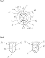
Fig. 1 shows the measuring scheme used to define the angles. An axis c is shown that extends from a top end t to a bottom end b of a powder chamber (not shown). Afirst wall section 11 and asecond wall section 12 extend along the axis c. The wall sections are only used by way of example to explain a measuring direction md. First angles α11 are measured from the axis c to thewall section 11, so that the acute angle is obtained. The same applies to second angles α12 that are formed between thesecond wall section 12 and the axis c. If the measuring direction is directed from the top end t to the bottom end b, the angles are counted positive. If the measuring direction md is directed from the bottom end b to the top end t, the angles are counted negative. Positive angles reach from 0 ° to < 90 °, negative angles reach from 0 ° to > -90 °. -
Fig. 2 shows two working principles of air-polishing devices, in particular ofpowder chambers 10. Thepowder chambers 10 are filled, for example, withpowder 1, such as sodium bicarbonate powder, which is steered up by pressurized air. The pressurized air gets into thepowder chambers 10 viaair inlets 20. An air/powder-mixture is transported viaoutlets 30, for example through a tube to a nozzle where water is added. In the left design ofFigure 2 , air and powder are mixed by combination of carburetor technique and swirling. Therefore, aventuri tube 83 is located within thepowder chamber 10. In the other type (shown right) the air/powder-mixture is created by swirling only. -
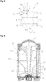
Fig. 3 shows apowder chamber 10 that extends along an axis c from a top end t to a bottom end b. Thepowder chamber 10 comprises afirst wall section 11 and asecond wall section 12. Thefirst wall section 11 forms a first angle α11 with the axis c. Thesecond wall section 12 forms a second angle α12 with the axis c. The first angle is, according to one embodiment, at least 20 °, preferably at least about 27 °. The second angle is smaller, as can be seen fromFigure 3 . This provides more space for the powder that is located within the powder chamber. Along the axis c, thefirst wall section 11 has a length l11 and thesecond wall section 12 has a length l12 which form appropriate volumes. -
Fig. 4 shows apowder chamber 10 similarly to that known fromFigure 3 . However, thepowder chamber 10 comprises also athird wall section 13. Asecond wall section 12 is basically parallel orientated with respect to an axis c forming a pit. In other words, a second angle α12 is basically 0° and thus smaller as a first angle α11 of thefirst wall section 11. A third angle α13 of thethird wall section 13 is bigger than the second angle α12 of thesecond wall section 12. Thewall sections Figure 4 shows a "double cone"-design. The first and the third angles α11, α13 are at least about 20 °, preferably at least about 25 ° or at least about 27 °. This means that an angulation of the cones is at least about 50 °, preferably at least about 55 °. -
Fig. 5 shows a further embodiment of apowder chamber 10 comprising threewall sections first wall section 11 forms a first angle α11 with respect to the axis c. The first angle α11 is bigger than 0 ° thus forming a first cone. A second angle α12 of thesecond wall section 12 is smaller than the first angle α11. In particular, the second angle α12 is negative whereby self-blockade can be prevented very effectively. A third angle α13 formed by thethird wall section 13 is bigger than the second angle α12. Actually, the third angle α13 is again positive (forming a second cone), similar to the first angle α11 whereby a very small third volume is formed which optimizes the emptying-behaviour and which reduces the residual powder left within thepowder chamber 10. -
Fig. 6 shows acontainer 80 as it is used in air-polishing devices. Within the container 80 apowder chamber 10 is arranged. Thepowder chamber 10 comprises afirst wall section 11, asecond wall section 12 and athird wall section 13. Thepowder chamber 10 extends along an axis c from a top end t to a bottom end b. The top end t of thepowder chamber 10 comprises a sealingportion 40 which seals in particular thefirst wall section 11 with respect to thecontainer 80. The bottom end b of thepowder chamber 10 comprises anair inlet 20. In the embodiment shown inFigure 6 , the top end t of thepowder chamber 10 is adapted to arrange an insert 82. The insert 82 comprises aventuri tube 83. Anoutlet 30 is adapted to bring/conduct an air/powder-mixture to an air polishing device (not shown). Expediently, the walls of thethird wall section 13 do not converge into an apex. Instead, aflat bottom plate 14 is formed which is adapted to avoid blocking of theair inlet 20 due to the powder which is in thepowder chamber 10.Figures 7a and 7b deal with this aspect in a more detailed way. -
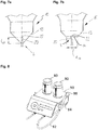
Fig. 7a shows apowder chamber 10, in particular a bottom end b and athird wall section 13. Anair inlet 20 extends into thepowder chamber 10, in particular into the volume formed by thethird wall section 13. A distance l22 which extends between the bottom end b and anozzle 22 of theair inlet 20 lies preferably within a range of about 1 to 5 mm. This prevents theair inlet 20 or thenozzle 22, respectively, from plugging/blocking with powder. -
Fig. 7b shows apowder chamber 10, similar to the one shown inFig. 7b . However, at a bottom endb a bottom plate 14 is formed. A diameter d14 lies according to some embodiments within a range of about 3 to 25 mm, preferably within a range of about 4 to 20 mm, in particular within a range of about 10 mm. Thebottom plate 14 avoids blocking/plugging of theair inlet 20 or thenozzle 22, respectively. As can be seen fromFig. 7b , thenozzle 22 extends also a little bit into the volume formed by athird wall section 13. This increases the effect of thebottom plate 14.Fig. 8 shows by way of example anair polishing device 90 comprising twocontainers 80 that are arranged at a basic device of theair polishing device 90. Aflexible tube 92 is arranged at the basic device. Theflexible tube 92 ends in ahand sample 94 that includes anozzle 96. Preferably, thecontainer 80 can be easily removed if a (inserted) powder chamber is empty. Alternatively, only the powder chamber that is arranged within the container may be removed to insert a new (full) one. -
- 1
- powder
- 10
- powder chamber
- 11
- first wall section
- 12
- second wall section
- 13
- third wall section
- 14
- bottom plate
- d14
- diameter (bottom plate)
- α11
- angle (first wall section)
- α12
- angle (second wall section)
- α13
- angle (third wall section)
- l11
- length of the first wall section
- l12
- length of the second wall section
- l13
- length of the third wall section
- 20
- (air) inlet
- 22
- nozzle
- l22
- distance (nozzle - bottom end)
- 30
- outlet
- 40
- sealing portion
- 80
- container
- 82
- insert
- 83
- venturi tube
- 84
- thread
- 90
- air polishing device
- 92
- flexible tube
- 94
- hand sample
- 96
- nozzle
- c
- axis
- t
- top end
- b
- bottom end
- md
- measuring direction
Claims (12)
- Powder chamber (10) for an air polishing device (80),
extending from a top end (t) to a bottom end (b) along an axis (c), said powder chamber (10) comprising at least two wall sections (11; 12), wherein a first wall section (11) forms a first angle (α11) with respect to the axis (c), and
wherein a second wall section (12) forms a second angle (α12) with respect to the axis (c),
wherein the angles (α11, α12) are measured in a measuring direction (md) from the axis (c) to the appropriate wall section (11; 12) in such a manner so that the acute angles are obtained,
wherein the measuring direction (md) from the top end (t) to the bottom end (b) is counted positive, and
wherein the measuring direction (md) from the bottom end (b) to the top end (t) is counted negative,
wherein the second wall section (12) is arranged below the first wall section (11), and
wherein the second angle (α12) is smaller than the first angle (α11), and wherein the powder chamber (10) comprises a third wall section (13) that forms a third angle (α13) with respect to the axis (c), and
wherein the third angle is bigger (α13) than the second angle (α12), and wherein the third wall section (13) is arranged below the second wall section (12), wherein the bottom end (b) comprises an air inlet (20), wherein a bottom plate (14) is arranged at the bottom end of the powder chamber (10) and/or the air inlet (20) extends into the powder chamber (10). - Powder chamber (10) according to claim 1,
wherein the first wall section (11) is inclined towards the axis (c) forming a first angle (α11) > 0. - Powder chamber (10) according to claim 1 or 2,
wherein the first angle (α11) and/or the third angle (α13) is at least 15 °, preferably at least 25 °. - Powder chamber (10) according to any of the preceding claims,
wherein the second angle (α12) is basically 0 °. - Powder chamber (10) according to any of claims 2-4,
wherein a volume (v13) of the powder chamber (10), limited by the third wall section (13), is less than 25 % of a complete volume of the powder chamber (10). - Powder chamber (10) according to any of the preceding claims,
wherein a length (l12) of the second wall section (12) is at least about 5 mm. - Powder chamber (10) according to claim 6,
wherein a ratio between the length (l12) of the second wall section (12) and a length (l13) of the third wall section (13) is less than 1. - Powder chamber (10) according to any of claims 6-7,
wherein a ratio between a length (l11) of the first wall section (11) and the length (l12) of the second wall section (12) is bigger than 1. - Powder chamber (10) according to any of the preceding claims,
wherein the powder chamber (10) is rotation symmetric. - Powder chamber (10) according to any of the preceding claims,
wherein the top end (t) comprises a sealing portion (40). - Powder chamber (10) according to any of the preceding claims,
wherein a venturi tube (83) is arranged in or at the powder chamber (10). - Air polishing device (90) comprising a powder chamber (10) according to any of claims 1-11.
Priority Applications (7)
| Application Number | Priority Date | Filing Date | Title |
|---|---|---|---|
| EP15186315.6A EP3146933B1 (en) | 2015-09-22 | 2015-09-22 | Powder chamber for an air-polishing device and air-polishing device |
| JP2018513582A JP2018527105A (en) | 2015-09-22 | 2016-07-04 | Powder chamber for air polishing apparatus and air polishing apparatus |
| CN201680049651.7A CN107920867A (en) | 2015-09-22 | 2016-07-04 | Powder chamber and air burnishing device for air burnishing device |
| PCT/EP2016/065658 WO2017050451A1 (en) | 2015-09-22 | 2016-07-04 | Powder chamber for an air-polishing device and air-polishing device |
| US15/761,682 US20180360559A1 (en) | 2015-09-22 | 2016-07-04 | Powder chamber for an air-polishing device and air-polishing device |
| CN202111267746.5A CN114012611A (en) | 2015-09-22 | 2016-07-04 | Powder chamber for air polishing device and air polishing device |
| JP2022109511A JP2022133419A (en) | 2015-09-22 | 2022-07-07 | Powder chamber for air-polishing device and air-polishing device |
Applications Claiming Priority (1)
| Application Number | Priority Date | Filing Date | Title |
|---|---|---|---|
| EP15186315.6A EP3146933B1 (en) | 2015-09-22 | 2015-09-22 | Powder chamber for an air-polishing device and air-polishing device |
Publications (2)
| Publication Number | Publication Date |
|---|---|
| EP3146933A1 EP3146933A1 (en) | 2017-03-29 |
| EP3146933B1 true EP3146933B1 (en) | 2019-11-20 |
Family
ID=54249305
Family Applications (1)
| Application Number | Title | Priority Date | Filing Date |
|---|---|---|---|
| EP15186315.6A Active EP3146933B1 (en) | 2015-09-22 | 2015-09-22 | Powder chamber for an air-polishing device and air-polishing device |
Country Status (5)
| Country | Link |
|---|---|
| US (1) | US20180360559A1 (en) |
| EP (1) | EP3146933B1 (en) |
| JP (2) | JP2018527105A (en) |
| CN (2) | CN114012611A (en) |
| WO (1) | WO2017050451A1 (en) |
Families Citing this family (4)
| Publication number | Priority date | Publication date | Assignee | Title |
|---|---|---|---|---|
| USD825741S1 (en) | 2016-12-15 | 2018-08-14 | Water Pik, Inc. | Oral irrigator handle |
| CN110730641B (en) | 2017-03-16 | 2022-03-25 | 洁碧有限公司 | Oral irrigator handle for use with oral agents |
| USD868243S1 (en) | 2018-03-16 | 2019-11-26 | Water Pik, Inc. | Oral irrigator tip |
| KR102565615B1 (en) * | 2023-04-13 | 2023-08-10 | 최상진 | Implant sand blast machine |
Family Cites Families (12)
| Publication number | Priority date | Publication date | Assignee | Title |
|---|---|---|---|---|
| SE359766B (en) * | 1972-01-26 | 1973-09-10 | Atlas Copco Ab | |
| US3798841A (en) * | 1972-06-13 | 1974-03-26 | A Eppler | Pressure feed for sand blast abrasive |
| DE3212207A1 (en) * | 1982-04-01 | 1983-10-06 | Siemens Ag | DEVICE FOR THE SURFACE TREATMENT OF TEETH, INSULATION FOR THE REMOVAL OF DENTAL COATING |
| US4487582A (en) | 1983-02-18 | 1984-12-11 | Cooper Lasersonics, Inc. | Dental cleaning system |
| US6074135A (en) * | 1996-09-25 | 2000-06-13 | Innovative Technologies, Inc. | Coating or ablation applicator with debris recovery attachment |
| JP4171539B2 (en) * | 1998-06-09 | 2008-10-22 | 株式会社不二製作所 | Direct pressure continuous abrasive supply and injection method and apparatus |
| GB9825110D0 (en) | 1998-11-16 | 1999-01-13 | Medivance Instr Limited | Pneumatic device |
| SE0400282D0 (en) * | 2004-02-09 | 2004-02-09 | Microdrug Ag | Machine for volumetric filing of powders |
| WO2006044303A2 (en) * | 2004-10-14 | 2006-04-27 | Dentsply International Inc. | Air polishing dental prophylaxis system |
| EP2193758B1 (en) | 2007-03-19 | 2013-08-07 | Ferton Holding S.A. | Powder container with insert |
| DE102010020691B4 (en) * | 2010-05-17 | 2014-09-04 | Pieper Innovationsgesellschaft Mbh | Method and device for conveying and metering bulk material during vacuum suction blasting |
| CN104416470A (en) * | 2013-09-05 | 2015-03-18 | 陈均 | Sand blasting machine |
-
2015
- 2015-09-22 EP EP15186315.6A patent/EP3146933B1/en active Active
-
2016
- 2016-07-04 CN CN202111267746.5A patent/CN114012611A/en active Pending
- 2016-07-04 JP JP2018513582A patent/JP2018527105A/en active Pending
- 2016-07-04 CN CN201680049651.7A patent/CN107920867A/en active Pending
- 2016-07-04 US US15/761,682 patent/US20180360559A1/en active Pending
- 2016-07-04 WO PCT/EP2016/065658 patent/WO2017050451A1/en active Application Filing
-
2022
- 2022-07-07 JP JP2022109511A patent/JP2022133419A/en active Pending
Non-Patent Citations (1)
| Title |
|---|
| None * |
Also Published As
| Publication number | Publication date |
|---|---|
| JP2018527105A (en) | 2018-09-20 |
| WO2017050451A1 (en) | 2017-03-30 |
| CN114012611A (en) | 2022-02-08 |
| US20180360559A1 (en) | 2018-12-20 |
| EP3146933A1 (en) | 2017-03-29 |
| CN107920867A (en) | 2018-04-17 |
| JP2022133419A (en) | 2022-09-13 |
Similar Documents
| Publication | Publication Date | Title |
|---|---|---|
| EP3146933B1 (en) | Powder chamber for an air-polishing device and air-polishing device | |
| JP5039042B2 (en) | Dispenser device for supplying the required amount of powder or paste material | |
| US7401973B1 (en) | Dust-free low pressure mixing system | |
| US20030224704A1 (en) | Rotary media valve | |
| JP2000118501A (en) | Power processor | |
| KR19980701240A (en) | Device for the Dosing of Granular, Pourable Material, in Particular Blasting Shots | |
| DE19652860C2 (en) | Device for conveying toner material from a storage container | |
| EP2604552A1 (en) | Apparatus for wetting particulate material | |
| KR100886581B1 (en) | Apparatus and method for increasing density of finely divided particulate matter | |
| JP2008529904A (en) | Apparatus for dispensing at least one particulate material into a container, filling apparatus, and filling method using such apparatus | |
| US7618182B1 (en) | Dust-free low pressure mixing system with jet ring adapter | |
| JP7462608B2 (en) | Powder supply method and method for producing thermoplastic resin composition | |
| CN109311062B (en) | Device and method for feeding plastic particles and liquid jointly into a purification device | |
| JP2009247999A (en) | Mixer | |
| US6315011B1 (en) | Air-relief filter nozzle assemblies | |
| US8727182B2 (en) | Feeder for particle delivery | |
| US20140233343A1 (en) | Tools for precisely, consistently, and reliably propelling a wide range of particulate media | |
| US20170029218A1 (en) | Dosing method and dosing device for particles of bulk material | |
| US8297541B2 (en) | Dust reduction in delivery of particulate commodities | |
| JP5665080B2 (en) | Powder filling device | |
| US8172645B2 (en) | Dosing device | |
| RU2083459C1 (en) | Pneumatic transport installation for vacuum reloading of powder material from container into package with small-size filling neck | |
| CN108529142A (en) | A kind of powder feeder for conveying fine powder | |
| RU2309884C1 (en) | Pneumotransport loose material dispensing plant | |
| CN116438039A (en) | For CO from 2 Preparation of CO from snow 2 Apparatus and method for particles and cleaning appliance |
Legal Events
| Date | Code | Title | Description |
|---|---|---|---|
| PUAI | Public reference made under article 153(3) epc to a published international application that has entered the european phase |
Free format text: ORIGINAL CODE: 0009012 |
|
| STAA | Information on the status of an ep patent application or granted ep patent |
Free format text: STATUS: THE APPLICATION HAS BEEN PUBLISHED |
|
| AK | Designated contracting states |
Kind code of ref document: A1 Designated state(s): AL AT BE BG CH CY CZ DE DK EE ES FI FR GB GR HR HU IE IS IT LI LT LU LV MC MK MT NL NO PL PT RO RS SE SI SK SM TR |
|
| AX | Request for extension of the european patent |
Extension state: BA ME |
|
| STAA | Information on the status of an ep patent application or granted ep patent |
Free format text: STATUS: REQUEST FOR EXAMINATION WAS MADE |
|
| 17P | Request for examination filed |
Effective date: 20170509 |
|
| RBV | Designated contracting states (corrected) |
Designated state(s): AL AT BE BG CH CY CZ DE DK EE ES FI FR GB GR HR HU IE IS IT LI LT LU LV MC MK MT NL NO PL PT RO RS SE SI SK SM TR |
|
| STAA | Information on the status of an ep patent application or granted ep patent |
Free format text: STATUS: EXAMINATION IS IN PROGRESS |
|
| 17Q | First examination report despatched |
Effective date: 20190204 |
|
| GRAP | Despatch of communication of intention to grant a patent |
Free format text: ORIGINAL CODE: EPIDOSNIGR1 |
|
| STAA | Information on the status of an ep patent application or granted ep patent |
Free format text: STATUS: GRANT OF PATENT IS INTENDED |
|
| INTG | Intention to grant announced |
Effective date: 20190716 |
|
| GRAS | Grant fee paid |
Free format text: ORIGINAL CODE: EPIDOSNIGR3 |
|
| GRAA | (expected) grant |
Free format text: ORIGINAL CODE: 0009210 |
|
| STAA | Information on the status of an ep patent application or granted ep patent |
Free format text: STATUS: THE PATENT HAS BEEN GRANTED |
|
| AK | Designated contracting states |
Kind code of ref document: B1 Designated state(s): AL AT BE BG CH CY CZ DE DK EE ES FI FR GB GR HR HU IE IS IT LI LT LU LV MC MK MT NL NO PL PT RO RS SE SI SK SM TR |
|
| REG | Reference to a national code |
Ref country code: GB Ref legal event code: FG4D |
|
| REG | Reference to a national code |
Ref country code: CH Ref legal event code: EP |
|
| REG | Reference to a national code |
Ref country code: IE Ref legal event code: FG4D |
|
| REG | Reference to a national code |
Ref country code: DE Ref legal event code: R096 Ref document number: 602015041955 Country of ref document: DE |
|
| REG | Reference to a national code |
Ref country code: AT Ref legal event code: REF Ref document number: 1203301 Country of ref document: AT Kind code of ref document: T Effective date: 20191215 |
|
| REG | Reference to a national code |
Ref country code: CH Ref legal event code: NV Representative=s name: HEPP WENGER RYFFEL AG, CH |
|
| REG | Reference to a national code |
Ref country code: NL Ref legal event code: FP |
|
| REG | Reference to a national code |
Ref country code: LT Ref legal event code: MG4D |
|
| PG25 | Lapsed in a contracting state [announced via postgrant information from national office to epo] |
Ref country code: NO Free format text: LAPSE BECAUSE OF FAILURE TO SUBMIT A TRANSLATION OF THE DESCRIPTION OR TO PAY THE FEE WITHIN THE PRESCRIBED TIME-LIMIT Effective date: 20200220 Ref country code: LT Free format text: LAPSE BECAUSE OF FAILURE TO SUBMIT A TRANSLATION OF THE DESCRIPTION OR TO PAY THE FEE WITHIN THE PRESCRIBED TIME-LIMIT Effective date: 20191120 Ref country code: GR Free format text: LAPSE BECAUSE OF FAILURE TO SUBMIT A TRANSLATION OF THE DESCRIPTION OR TO PAY THE FEE WITHIN THE PRESCRIBED TIME-LIMIT Effective date: 20200221 Ref country code: LV Free format text: LAPSE BECAUSE OF FAILURE TO SUBMIT A TRANSLATION OF THE DESCRIPTION OR TO PAY THE FEE WITHIN THE PRESCRIBED TIME-LIMIT Effective date: 20191120 Ref country code: FI Free format text: LAPSE BECAUSE OF FAILURE TO SUBMIT A TRANSLATION OF THE DESCRIPTION OR TO PAY THE FEE WITHIN THE PRESCRIBED TIME-LIMIT Effective date: 20191120 Ref country code: BG Free format text: LAPSE BECAUSE OF FAILURE TO SUBMIT A TRANSLATION OF THE DESCRIPTION OR TO PAY THE FEE WITHIN THE PRESCRIBED TIME-LIMIT Effective date: 20200220 Ref country code: SE Free format text: LAPSE BECAUSE OF FAILURE TO SUBMIT A TRANSLATION OF THE DESCRIPTION OR TO PAY THE FEE WITHIN THE PRESCRIBED TIME-LIMIT Effective date: 20191120 |
|
| PG25 | Lapsed in a contracting state [announced via postgrant information from national office to epo] |
Ref country code: RS Free format text: LAPSE BECAUSE OF FAILURE TO SUBMIT A TRANSLATION OF THE DESCRIPTION OR TO PAY THE FEE WITHIN THE PRESCRIBED TIME-LIMIT Effective date: 20191120 Ref country code: IS Free format text: LAPSE BECAUSE OF FAILURE TO SUBMIT A TRANSLATION OF THE DESCRIPTION OR TO PAY THE FEE WITHIN THE PRESCRIBED TIME-LIMIT Effective date: 20200320 Ref country code: HR Free format text: LAPSE BECAUSE OF FAILURE TO SUBMIT A TRANSLATION OF THE DESCRIPTION OR TO PAY THE FEE WITHIN THE PRESCRIBED TIME-LIMIT Effective date: 20191120 |
|
| PG25 | Lapsed in a contracting state [announced via postgrant information from national office to epo] |
Ref country code: AL Free format text: LAPSE BECAUSE OF FAILURE TO SUBMIT A TRANSLATION OF THE DESCRIPTION OR TO PAY THE FEE WITHIN THE PRESCRIBED TIME-LIMIT Effective date: 20191120 |
|
| PG25 | Lapsed in a contracting state [announced via postgrant information from national office to epo] |
Ref country code: PT Free format text: LAPSE BECAUSE OF FAILURE TO SUBMIT A TRANSLATION OF THE DESCRIPTION OR TO PAY THE FEE WITHIN THE PRESCRIBED TIME-LIMIT Effective date: 20200412 Ref country code: ES Free format text: LAPSE BECAUSE OF FAILURE TO SUBMIT A TRANSLATION OF THE DESCRIPTION OR TO PAY THE FEE WITHIN THE PRESCRIBED TIME-LIMIT Effective date: 20191120 Ref country code: CZ Free format text: LAPSE BECAUSE OF FAILURE TO SUBMIT A TRANSLATION OF THE DESCRIPTION OR TO PAY THE FEE WITHIN THE PRESCRIBED TIME-LIMIT Effective date: 20191120 Ref country code: DK Free format text: LAPSE BECAUSE OF FAILURE TO SUBMIT A TRANSLATION OF THE DESCRIPTION OR TO PAY THE FEE WITHIN THE PRESCRIBED TIME-LIMIT Effective date: 20191120 Ref country code: RO Free format text: LAPSE BECAUSE OF FAILURE TO SUBMIT A TRANSLATION OF THE DESCRIPTION OR TO PAY THE FEE WITHIN THE PRESCRIBED TIME-LIMIT Effective date: 20191120 Ref country code: EE Free format text: LAPSE BECAUSE OF FAILURE TO SUBMIT A TRANSLATION OF THE DESCRIPTION OR TO PAY THE FEE WITHIN THE PRESCRIBED TIME-LIMIT Effective date: 20191120 |
|
| REG | Reference to a national code |
Ref country code: DE Ref legal event code: R097 Ref document number: 602015041955 Country of ref document: DE |
|
| PG25 | Lapsed in a contracting state [announced via postgrant information from national office to epo] |
Ref country code: SM Free format text: LAPSE BECAUSE OF FAILURE TO SUBMIT A TRANSLATION OF THE DESCRIPTION OR TO PAY THE FEE WITHIN THE PRESCRIBED TIME-LIMIT Effective date: 20191120 Ref country code: SK Free format text: LAPSE BECAUSE OF FAILURE TO SUBMIT A TRANSLATION OF THE DESCRIPTION OR TO PAY THE FEE WITHIN THE PRESCRIBED TIME-LIMIT Effective date: 20191120 |
|
| PLBE | No opposition filed within time limit |
Free format text: ORIGINAL CODE: 0009261 |
|
| STAA | Information on the status of an ep patent application or granted ep patent |
Free format text: STATUS: NO OPPOSITION FILED WITHIN TIME LIMIT |
|
| 26N | No opposition filed |
Effective date: 20200821 |
|
| PG25 | Lapsed in a contracting state [announced via postgrant information from national office to epo] |
Ref country code: PL Free format text: LAPSE BECAUSE OF FAILURE TO SUBMIT A TRANSLATION OF THE DESCRIPTION OR TO PAY THE FEE WITHIN THE PRESCRIBED TIME-LIMIT Effective date: 20191120 Ref country code: SI Free format text: LAPSE BECAUSE OF FAILURE TO SUBMIT A TRANSLATION OF THE DESCRIPTION OR TO PAY THE FEE WITHIN THE PRESCRIBED TIME-LIMIT Effective date: 20191120 |
|
| PG25 | Lapsed in a contracting state [announced via postgrant information from national office to epo] |
Ref country code: MC Free format text: LAPSE BECAUSE OF FAILURE TO SUBMIT A TRANSLATION OF THE DESCRIPTION OR TO PAY THE FEE WITHIN THE PRESCRIBED TIME-LIMIT Effective date: 20191120 |
|
| PG25 | Lapsed in a contracting state [announced via postgrant information from national office to epo] |
Ref country code: LU Free format text: LAPSE BECAUSE OF NON-PAYMENT OF DUE FEES Effective date: 20200922 |
|
| PG25 | Lapsed in a contracting state [announced via postgrant information from national office to epo] |
Ref country code: TR Free format text: LAPSE BECAUSE OF FAILURE TO SUBMIT A TRANSLATION OF THE DESCRIPTION OR TO PAY THE FEE WITHIN THE PRESCRIBED TIME-LIMIT Effective date: 20191120 Ref country code: MT Free format text: LAPSE BECAUSE OF FAILURE TO SUBMIT A TRANSLATION OF THE DESCRIPTION OR TO PAY THE FEE WITHIN THE PRESCRIBED TIME-LIMIT Effective date: 20191120 Ref country code: CY Free format text: LAPSE BECAUSE OF FAILURE TO SUBMIT A TRANSLATION OF THE DESCRIPTION OR TO PAY THE FEE WITHIN THE PRESCRIBED TIME-LIMIT Effective date: 20191120 |
|
| PG25 | Lapsed in a contracting state [announced via postgrant information from national office to epo] |
Ref country code: MK Free format text: LAPSE BECAUSE OF FAILURE TO SUBMIT A TRANSLATION OF THE DESCRIPTION OR TO PAY THE FEE WITHIN THE PRESCRIBED TIME-LIMIT Effective date: 20191120 |
|
| P01 | Opt-out of the competence of the unified patent court (upc) registered |
Effective date: 20230530 |
|
| PGFP | Annual fee paid to national office [announced via postgrant information from national office to epo] |
Ref country code: NL Payment date: 20230920 Year of fee payment: 9 Ref country code: IE Payment date: 20230918 Year of fee payment: 9 Ref country code: GB Payment date: 20230921 Year of fee payment: 9 Ref country code: AT Payment date: 20230915 Year of fee payment: 9 |
|
| PGFP | Annual fee paid to national office [announced via postgrant information from national office to epo] |
Ref country code: FR Payment date: 20230919 Year of fee payment: 9 Ref country code: DE Payment date: 20230724 Year of fee payment: 9 Ref country code: BE Payment date: 20230918 Year of fee payment: 9 |
|
| PGFP | Annual fee paid to national office [announced via postgrant information from national office to epo] |
Ref country code: IT Payment date: 20230929 Year of fee payment: 9 Ref country code: CH Payment date: 20231001 Year of fee payment: 9 |