EP3146877B1 - Cabine de douche - Google Patents
Cabine de douche Download PDFInfo
- Publication number
- EP3146877B1 EP3146877B1 EP16189503.2A EP16189503A EP3146877B1 EP 3146877 B1 EP3146877 B1 EP 3146877B1 EP 16189503 A EP16189503 A EP 16189503A EP 3146877 B1 EP3146877 B1 EP 3146877B1
- Authority
- EP
- European Patent Office
- Prior art keywords
- wall
- wall element
- fitting
- rail
- screw
- Prior art date
- Legal status (The legal status is an assumption and is not a legal conclusion. Google has not performed a legal analysis and makes no representation as to the accuracy of the status listed.)
- Active
Links
Images


Classifications
-
- A—HUMAN NECESSITIES
- A47—FURNITURE; DOMESTIC ARTICLES OR APPLIANCES; COFFEE MILLS; SPICE MILLS; SUCTION CLEANERS IN GENERAL
- A47K—SANITARY EQUIPMENT NOT OTHERWISE PROVIDED FOR; TOILET ACCESSORIES
- A47K3/00—Baths; Douches; Appurtenances therefor
- A47K3/28—Showers or bathing douches
- A47K3/30—Screens or collapsible cabinets for showers or baths
- A47K3/36—Articulated screens
-
- A—HUMAN NECESSITIES
- A47—FURNITURE; DOMESTIC ARTICLES OR APPLIANCES; COFFEE MILLS; SPICE MILLS; SUCTION CLEANERS IN GENERAL
- A47K—SANITARY EQUIPMENT NOT OTHERWISE PROVIDED FOR; TOILET ACCESSORIES
- A47K3/00—Baths; Douches; Appurtenances therefor
- A47K3/28—Showers or bathing douches
- A47K3/30—Screens or collapsible cabinets for showers or baths
- A47K2003/307—Adjustable connections to the wall
Definitions
- the invention relates to a shower cubicle with at least one cubicle wall.
- shower cubicles generally have one or two cubicle walls arranged at an angle to one another, which close off the interior of the shower cubicle.
- the cabin wall consists of a fixed wall element and a door element pivotally connected to the wall element for opening and closing the shower cabin. It is known to fix the fixed wall element to a room wall, for example the wall of a bathroom, in such a way that the wall element is clamped with a vertical longitudinal edge in a U-profile of a wall rail fastened to the room wall.
- US 2003/019030 A1 discloses a shower cubicle with at least one cubicle wall, which has a fixed wall element and a door element pivotably connected to the wall element by means of fittings, the wall element being attachable to a room wall with a vertical longitudinal edge in a wall rail having a U-profile.
- the invention has for its object to provide a shower cubicle, the cubicle wall has an elegant appearance and is suitable in a largely uniform design for all installation situations.
- the cubicle wall has a fixed wall element and a door element pivotably connected to this wall element.
- the fixed wall element is attached to the respective room wall in such a way that this wall element is inserted with its one vertical longitudinal edge into the U-profile of a wall rail attached to the room wall and is clamped in this U-profile.
- the door element is pivotally connected to the wall element by means of an upper fitting and a lower fitting. These fittings are arranged so that the upper fitting is flush with the upper transverse edge of the door element and the wall element and, accordingly, the lower fitting is flush with the lower transverse edge of the door element and the wall element. This results in an elegant appearance of the fittings and thus the cabin wall.
- the fittings are fixed to the wall element with a fitting part which has two fastening means arranged next to one another parallel to the respective transverse edge.
- the arrangement of the fasteners next to each other enables a low vertical height of the respective fitting part, which is advantageous for the elegant appearance, without reducing the stability of the fastening.
- the fitting part has two cheek parts, between which the wall element is recorded.
- One fastening means passes through the first cheek part and the wall element and can be screwed into the opposite second cheek part, by tightening the screw the cheek parts are pulled towards each other around the wall element to pinch.
- the other fastening means is designed as a screw which is screwed into a threaded hole in the first cheek part and thereby presses the wall element against the second cheek part by clamping.
- the screw of the fastening means penetrating the wall element can preferably reach through a notch in the wall element which is formed in the transverse edge of the wall element.
- the notch can be placed close to the corner of the wall element, i.e. close to the vertical longitudinal edge. This enables the fitting part to be fastened close to the vertical edge without the risk of breaking the glass pane of the wall element.
- the wall rail has a recess in the U-profile at its upper and lower end for receiving the fixed wall element.
- the recess is formed in such a way that the bottom of the profile of the U-profile is missing in the end region and, if necessary, the inner surfaces of the legs of the U-profile are also removed, so that the wall thickness of the legs is reduced and the clear width between the legs is increased.
- This version is particularly suitable for installation situations in which the pivotable door element is to be attached directly to the wall of the room.
- the wall element is designed as a vertical bar, the horizontal transverse dimension of which can be very small and only has to be wide enough to accommodate the fitting part fastened to the wall element.
- the wall element can be inserted almost completely into the U-profile of the wall rail, the fitting parts of the upper and lower fitting fixed on the wall element into the respective upper and penetrate the lower recesses of the wall rail.
- the fixed wall part is therefore almost invisible when the cabin wall is installed and does not impair the appearance of the cabin wall.
- the wall element in this embodiment is preferably made of metal and can be designed, for example, as an aluminum profile rail.
- a major advantage of the invention is that the same fittings can be used with different designs of the fixed wall element.
- the wall element can be a pane of glass or plastic if the pivot axis of the door element is spaced from the room wall. If the door element is to be pivotally mounted directly on the wall of the room, a wall element is used which is inserted into the wall rail as a narrow strip or rail. In both cases, the cabin wall and fittings look attractive.
- the cabin wall can be assembled in the factory complete with wall element, door element and fittings.
- all you have to do is attach the wall rail to the wall of the room and insert the wall unit with its wall element into the U-profile of the wall rail and fix it in this wall rail.
- a fine alignment of the cabin wall with respect to the room wall is possible in that the wall element can be inserted and fixed at different depths in the U-profile of the wall rail.
- the installation of the pre-assembled cabin wall can be carried out easily and easily by a single person.
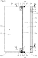
- Figure 1 shows a top view of a shower cubicle 10 with a first cubicle wall 20 and a second cubicle wall 20 '.
- the cabin walls 20, 20 ' are arranged at an angle to one another and delimit with two space walls 15, 16, z. B. building walls, the interior of the shower cabin 10.
- a rectangular interior is formed.
- the cabin wall 20 (cf. Figures 2a to 4 ) has a door element 30 and a wall element 40, which over at least one Fitting are pivotally connected to one another about a pivot axis S.
- a first fitting 60 is arranged in the lower region with the cabin wall 20, while a second fitting 70 is arranged in the upper region of the cabin wall 20.
- the door element 30 is essentially rectangular and has two parallel longitudinal edges 30a, 30b and two parallel transverse edges 30c, 30d. In the assembled state, the longitudinal edges 30a, 30b run essentially vertically, while the transverse edges 30c, 30d run essentially horizontally.
- the wall element 40 is also essentially rectangular with two longitudinal edges 40a, 40b arranged parallel to one another and two transverse edges 40c, 40d arranged parallel to one another.
- the longitudinal edges 40a, 40b run essentially vertically, while the transverse edges 40c, 40d run essentially horizontally.
- the longitudinal edge 40a in particular faces the door element 30, while the longitudinal edge 40b faces the corresponding room wall 15 on the side facing away from the door element 30.
- the wall element 40 engages in a wall rail 50 with its longitudinal edge 40b facing away from the door element 30.
- the wall rail 50 is designed as a U-shaped profile and has two legs 51 and 52 which are oriented essentially parallel to one another and which are connected to one another by a profile base 53.
- the U-profile has a depth t, which is measured from the free end of the legs 51, 52 to the profile base 53.
- the screws 56 can fix the wall element 40 in a clamping manner between the respective screw 56 and the second leg 52.
- the depth t of the U-profile of the wall rail 50 is dimensioned such that the wall element 40 can be clamped in the wall rail 50 in differently inserted positions.
- the bore 54 is sufficiently far from the profile base 53, for example by a distance a, which is at least 10 mm, advantageously at least 20 or even 30 mm.
- a fixation of the wall element 40 in the wall rail 50 is possible both when the wall element 40 is pushed into the U-profile up to the abutment against the profile base 53, but also when the wall element 40 from the U approximately by the distance a from this position Profile of the wall rail 50 is pulled out.
- the wall element 40 can also be fixed in the wall rail 50 in all intermediate positions. This enables a variation of the distance between the profile base 53 and the longitudinal edge 40a of the wall element 40 facing the door element 30 and thus a variation and adjustment of the width of the cabin wall 20, in particular approximately by a maximum of the distance a.
- the wall rail 50 is fixed to the room wall 15 in a manner described later in such a way that the profile base 53 bears against the room wall 15, while the essentially vertical legs 51, 52 protrude at right angles from the room wall 15.
- a sealing element 57 for example in the form of a sealing cord, is arranged between at least one of the legs 51, 52 and the wall element 40, advantageously between the two legs 51 and 52 and the wall element 40, in order to enable sealing against splash water.
- the sealing element 57 is preferably inserted in an inner groove 57 'of the respective leg 51 or 52 which runs in the longitudinal direction of the leg 51 or 52.
- the wall element 40 After assembly in the wall rail 50, the wall element 40 is fixed and rigidly fixed to the room wall 15.
- the door element 30 can be pivoted about the pivot axis S against the wall element 40 by means of the fittings 60, 70.
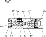
- the lower fitting 60 has a first fitting part 61 and a second fitting part 62.
- the first fitting part 61 is fastened to the door element 30, while the second fitting part 62 is fastened to the wall element 40.
- the first fitting part 61 has two cheek parts 61a and 61b which rest on the two sides of the door element 30.
- a clamping screw 61c passes through one cheek part 61b and a hole in the door element 30 and can be screwed into a threaded hole in the opposite cheek part 61a.
- the cheek parts 61a and 61b can thus be pulled against one another by means of the clamping screw 61c in order to hold the door element 30 lying between the cheek parts 61a and 61b in a clamping manner.
- the second fitting part 62 has two cheek parts 62a and 62b, which bear against the two sides of the wall element 40 and are fixed thereon.
- the second fitting part 62 has first fastening means 63 and second fastening means 65.
- the two fastening means 62 and 65 are arranged next to one another in the direction parallel to the transverse edge 40c, 40d.
- the first fastening means 63 has a screw 64c which is screwed into a bore 64a with an internal thread 64b arranged in the first cheek part 62a.
- the wall element 40 arranged between the two cheek parts 62a, 62b is pressed by the screw 64c against the other cheek part 62b and is clampingly fixed between the screw 64c and the second cheek part 62b.
- the second fastening means 65 has a screw 66d which extends through a bore 66a provided in the first cheek part 62a and a recess arranged in the wall element 40 and is screwed into a bore 66b arranged in the opposite cheek part 62b with an internal thread 66c.
- the screw 66d braces the two cheek parts 62a and 62b against one another in order to fix the wall element 40 arranged between the cheek parts 62a, 62b in a clamping manner.
- the recess arranged in the wall element 40 is advantageously designed as a notch 46, which starts from the corresponding transverse edge 40c or 40d and, for example, leads approximately parallel to the respective longitudinal edge 40a into the wall element 40 (cf.
- the design of the recess as a notch 46 has the advantage over the design as a bore that, in the case of a wall element 40 made of glass, the notch 46 can be arranged close to the longitudinal edge 40a without the risk of glass breakage.
- the second fitting part 62 can thereby be designed to be particularly compact, since in the direction parallel to the longitudinal edge 40a of the wall element 40, only a height of the fitting part 62 is required which is sufficient to provide sufficient contact surface for the heads of the screws 64c and 66d.
- the two fastening means 63 and 65 arranged side by side enable the wall element 40 to be securely fixed in the fitting part 62 in the smallest space.
- the fitting parts 62 and 61 lie flush with the edges on the transverse edges 40d and 30d of the wall element 40 and the door element 30, respectively. This advantageously combines a stable fastening of the fitting with elegant minimal dimensions.
- the lower fitting 60 can have a lifting / lowering mechanism 67, which is basically known from the prior art and serves to raise the door element 30 in the vertical direction when pivoting from a closed position, so that the door element 30 during the pivoting movement does not touch the floor, but in the closed position it is lowered to seal the floor.
- a lifting / lowering mechanism 67 which is basically known from the prior art and serves to raise the door element 30 in the vertical direction when pivoting from a closed position, so that the door element 30 during the pivoting movement does not touch the floor, but in the closed position it is lowered to seal the floor.
- the upper fitting 70 is designed essentially in accordance with the lower fitting 60 and differs from the fitting 60 in that instead of the lifting-lowering mechanism 67, a bearing pin 77 is provided, around which the pivoting movement of the door element 30 takes place.
- the fitting parts of the upper fitting 70 also lie flush with the edges on the upper transverse edges 30c or 40c of the door element 30 or the wall element 40.
- the Figures 5 . 6 and 7 show the Figures 2 . 3 and 4 corresponding views of the second cabin wall 20 '.
- the same reference numerals designate the same parts.
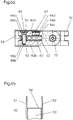
- the wall rail 50 ' has recesses 58' at its upper and lower ends which are for receiving a section of the second fitting part 62 (cf. Figure 6b ).
- the recesses 58 ′ are formed in that only the legs 51 and 52 of the U-profile remain with a reduced wall thickness, while the profile base 53 is removed and the clear width between the legs 51 and 52 by reducing the material on the inside of these legs 51 and 52 is expanded.
- the second fitting parts 62 of the upper fitting 60 or of the lower fitting 70 can be inserted into the corresponding upper and lower recesses 58 'to such an extent that essentially only the sections of these fitting parts 62 with the pivot axis S outside the legs 51 and 52 of the wall rail 50 'are located like this in Figure 6a you can see.
- the wall element 40 ', which is clamped in the lower and upper second fitting parts 62, is designed in this embodiment as a narrow rail, which is almost completely accommodated in the profile depth t of the wall rail 50'.
- the door element 30 with the pivot axis S can be mounted so close to the wall rail 50 'that there is no difference in distance from a shower cubicle in which the door element is mounted directly on the room wall by means of fittings.
- the design of the fittings 60 and 70 and the fastening of the wall rail 50 ' is identical, regardless of whether a wall element 40 of greater width or a narrow wall element 40 'is used.
- the wall element 40' advantageously has a vertically continuous groove 42 in its end edge facing the door element 30, into which a seal 44 ( Figure 9 ) is used.
- the seal 44 has a web adapted to the groove 42, which for example can have ribs for better fixation in the groove 42, and a rounded mushroom-shaped head adjoining the web, which covers the end face of the wall element 40 ′ facing the door element 30.
- the mushroom-shaped head is advantageously flexible, e.g. B. hollow to take into account the changing distance between the door element 30 facing longitudinal edge 40a of the wall element 40 'and the wall element 40' facing longitudinal edge 30b of the door element 30 when pivoting the door element 30 relative to the wall element 40 '.
- the door element 30 is preferably made of glass or plastic and is advantageously transparent.
- the wall element 40 is preferably made in accordance with the door element 30 from glass or a transparent plastic. If a wall element 40 'of small width is provided, which is almost completely accommodated in the wall rail 50', the wall element 40 'can preferably also be made of metal in view of the higher stability.
- the wall element 40 ' is expediently an aluminum profile with internal cavities, as is the case with Figures 6a and 7 demonstrate. This design combines high stability with low weight and material requirements.
- the wall rail 50 has a U-profile with two legs 51 and 52 and a profile base 53 connecting these legs. In one of the legs 52, the bores 54 are formed, into which the screws 56 for screwing in the wall element 40/40 'are screwed.
- the profile base 53 of the wall rail 50 has at least two openings 80 spaced apart in the longitudinal direction. The openings 80 are arranged centrally in the profile base 53. In the interior of the U-profile of the wall rail 50, the clear inner width between the legs 51 and 52 is widened in the form of a cylinder 81 coaxial with the opening 80 after the opening 80.
- the opening 80 has a diameter which is larger than the diameter of the cylinder 81 and consequently also larger than the clear inner width between the legs 51 and 52.
- the opening 80 forms a circular-shaped receiving space 82 which is open towards the outside of the profile base 53 and is limited towards the inside by the legs 51 and 52, as in FIGS Figures 11 and 12 can be seen.
- the receiving space 82 is formed with an internal thread.
- an adjusting disk 83 is inserted, which as an individual part in Figure 15 is shown in axial section.
- the adjusting disk 83 has the shape of an annular disk, the outside diameter of which is smaller than the inside diameter of the receiving space 82, but larger than the inside diameter of the cylinder 81.
- the inside diameter of the adjusting disk 83 corresponds to the diameter of the screws 84 with which the wall rail 50 is fastened to the respective room wall 15 is attached.
- the thickness of the adjusting disk 83 is smaller than the thickness of the profile base 53.
- a cover screw 85 which has the shape of a circular washer, the external thread of which corresponds to the internal thread of the receiving space 82.
- the inside diameter of the cover screw 85 is larger than the inside diameter of the adjustment disk 83, but smaller than the outside diameter of the adjustment disk 83.
- the thickness of the cover screw 85 is less than the thickness of the profile base 53.
- the adjusting disk 83 is held in the receiving space 82, but is radially displaceable in this due to its smaller outside diameter than the inside diameter of the receiving space 82.
- the assembly of the wall rail 50, 50 ' can be carried out in a simple manner by a single person in the following manner.
- the position of the wall rails 50, 50 ' is determined using a template representing the floor plan dimensions of the shower cabin 10.
- the wall rails 50, 50 ′ are attached to the respective room wall 15, 16 in a vertically aligned manner, which is preferably done by using adhesive pads attached to the outside of the profile base 53, which are adjacent to the room wall 15, 16.
- guide bushings 86 are inserted into the respective expanded cylinders 81.
- the guide bushings 86 which can be made of plastic, for example, have a cylindrical shape, the outer diameter of which corresponds to the inner diameter of the cylinder 81, so that the guide bushings 86 can be inserted into the expanded cylinders 81 without play.
- the guide bushing 86 is preferably held in the cylinder 81 in a rotationally secure manner.
- the inside diameter of the guide bushings 86 corresponds to the diameter of a drill 87, which in Figure 15 is partially shown.
- the drill 87 can now be guided through the guide bushing 86 in an axially precise manner through the opening 80, the adjusting disk 83 and the cover screw 85 into the room wall 15 or 16 in order to predrill a suitable borehole there.
- the provisionally fixed wall rail 50, 50 ' is removed again from the room wall 15, 16.
- the pre-drilled boreholes can now be expanded using a drill with a larger diameter in order to insert dowels in these boreholes.
- the guide bushings 86 are now removed from the wall rails 50, 50 'and the wall rails 50, 50' are positioned again on the respective room wall 15, 16. Now the screws 84 are inserted and screwed through the adjusting disk 83 into the respective dowel.
- the diameter of the screws 84 corresponds to the inside diameter of the adjusting disk 83, while the diameter of the screw head corresponds to the inside diameter of the expanded cylinder 81.
- the screw 84 can thus be inserted through the cylinder 81, inserts with its screw head into the conical inner diameter of the adjusting disk 83, so that when the screw 84 is screwed into the dowel, the adjusting disk 83 against the wall rail 50, 50 'against the cover screw 85 the room wall 15, 16 braced and fixed. Before the screw 84 is tightened, it is still possible to readjust the exact position of the wall rail 50, 50 ', since the adjusting disk 83 can be displaced with radial screw in the receiving space 82 with the screw 84, so that the wall rail 50, 50' relative to the screw 84 is slightly displaceable.
- the assembly of the wall rail 50, 50 ' has the advantage that this assembly can be carried out by an individual without additional aids can be carried out easily and precisely.
- the arrangement of the screws 84 in the profile base 53 of the wall rails 50, 50 ' is invisible after the wall rail 50, 50' has been installed, so that the wall rail has an attractive appearance with high stability, without widening of the wall rail being necessary.
- the inserted and screwed-in screws 84 are covered by the wall elements 40, 40 'subsequently inserted into the wall rails 50, 50'.
Landscapes
- Health & Medical Sciences (AREA)
- Public Health (AREA)
- Epidemiology (AREA)
- General Health & Medical Sciences (AREA)
- Hinges (AREA)
- Body Structure For Vehicles (AREA)
- Support Devices For Sliding Doors (AREA)
Claims (6)
- Cabine de douche ayant au moins une paroi de cabine (20, 20') qui comporte un élément de paroi fixe (40, 40') et un élément de porte (30) articulé sur l'élément de paroi (40, 40') au moyen de ferrures (60, 70), l'élément de paroi (40, 40') pouvant être bloqué par un bord longitudinal vertical (40b) dans un rail de paroi (50, 50') ayant un profil en U pouvant être fixé sur une paroi d'un espace (15, 16),
une ferrure supérieure (70) s'appliquant sur l'élément de porte (30) et sur l'élément de paroi (40, 40') en étant au même niveau que leur bord transversal supérieur (30c ou 40c),
une ferrure inférieure (60) s'appliquent sur l'élément de porte (30) et l'élément de paroi (40, 40') en étant au même niveau que leur bord transversal inférieur (30d ou 40d),
la ferrure supérieure (70) et la ferrure intérieure (60) étant respectivement bloquées sur l'élément de paroi (40, 40') avec une partie de ferrure (62) par l'intermédiaire de deux moyens de fixation (63, 65) installés côte à côte parallèlement au bord transversal (40c, 40d) respectif,
la partie de ferrure (62) comprenant deux parties de flasque parallèles (62a, 62b) entre lesquelles est logé l'élément de paroi (40, 40'),
un premier moyen de fixation (63) étant réalisé sous la forme d'une vis (64c) qui est vissée dans un perçage (64a) ayant un filetage interne (64b) de la première partie de flasque (62a) et applique à force l'élément de paroi (40, 40') contre la seconde partie de flasque (62b), et
un second moyen de fixation (65) étant réalisé sous la forme d'une vis (66d) qui traverse la première partie de flasque (62a) et l'élément de paroi (40, 40') et peut être vissée dans un filetage interne (66c) d'un perçage (66b) de la seconde partie de flasque (62b). - Cabine de douche conforme à la revendication 1,
caractérisée en ce que
l'élément de paroi (40, 40') est une vitre en verre ou en matériau synthétique. - Cabine de douche conforme à la revendication 2,
caractérisée en ce que
l'élément de paroi (40, 40') comporte dans les bords transversaux horizontaux (30c, 40c) respectifs à proximité du bord longitudinal vertical (40a) une entaille (46) qui est traversée par la vis (66d) du second moyen de fixation (65). - Cabine de douche conforme à la revendication 1,
caractérisée en ce que
l'élément de paroi (40, 40') est réalisé sous la forme d'une étroite baguette métallique qui est en grande partie logée dans le profil en U du rail de paroi (50, 50'). - Cabine de douche conforme à l'une des revendications précédentes,
caractérisée en ce que
le profil en U du rail de paroi (50, 50') comporte à son extrémité supérieure et à son extrémité intérieure des évidements (58') dans la base de profil (53) et le cas échéant dans les surfaces internes des branches (51, 52) de celui-ci. - Cabine de douche conforme à la revendication 5,
caractérisée en ce que
la partie de ferrure (62) montée sur l'élément de paroi (40, 40') de la ferrure supérieure (70) et de la ferrure inférieure (60) peut être introduite dans l'évidement (58) respectif.
Applications Claiming Priority (1)
| Application Number | Priority Date | Filing Date | Title |
|---|---|---|---|
| DE102015116200.8A DE102015116200A1 (de) | 2015-09-24 | 2015-09-24 | Duschkabine |
Publications (3)
| Publication Number | Publication Date |
|---|---|
| EP3146877A1 EP3146877A1 (fr) | 2017-03-29 |
| EP3146877B1 true EP3146877B1 (fr) | 2020-02-26 |
| EP3146877B8 EP3146877B8 (fr) | 2020-05-06 |
Family
ID=56943437
Family Applications (1)
| Application Number | Title | Priority Date | Filing Date |
|---|---|---|---|
| EP16189503.2A Active EP3146877B8 (fr) | 2015-09-24 | 2016-09-19 | Cabine de douche |
Country Status (2)
| Country | Link |
|---|---|
| EP (1) | EP3146877B8 (fr) |
| DE (1) | DE102015116200A1 (fr) |
Families Citing this family (1)
| Publication number | Priority date | Publication date | Assignee | Title |
|---|---|---|---|---|
| US10349784B2 (en) * | 2017-06-01 | 2019-07-16 | Bath Authority Llc | Hinged wall profile door |
Family Cites Families (7)
| Publication number | Priority date | Publication date | Assignee | Title |
|---|---|---|---|---|
| DE9012039U1 (fr) * | 1990-08-21 | 1991-01-17 | Dorma-Glas Gesellschaft Fuer Glastuerbeschlaege Und -Konstruktionen Mbh, 4902 Bad Salzuflen, De | |
| DE29701915U1 (de) * | 1997-02-04 | 1997-05-22 | Lido Duschabtrennungen | Wandbefestigung für eine feststehende Glaswand |
| DE10119987C2 (de) * | 2001-04-23 | 2003-10-02 | Dorma Gmbh & Co Kg | Befestigungsvorrichtung zur Befestigung von flächenförmigen Materialien an einem stabartigen Bauteil |
| US6618871B2 (en) * | 2001-07-24 | 2003-09-16 | Kohler Co. | Shower door assembly |
| US6643898B1 (en) * | 2002-05-18 | 2003-11-11 | Southeastern Aluminum Products, Inc. | Self-centering pivot door hinge system |
| AT9075U1 (de) * | 2005-10-10 | 2007-04-15 | Neher Bad & Wellness Systems G | Vorrichtung zum befestigen |
| DE102011012354B3 (de) | 2011-02-24 | 2012-01-26 | Aberle GmbH & Co KG, Präzisionsdrehteile | Beschlag für eine Scheibe, insbesondere eine Glasscheibe |
-
2015
- 2015-09-24 DE DE102015116200.8A patent/DE102015116200A1/de not_active Withdrawn
-
2016
- 2016-09-19 EP EP16189503.2A patent/EP3146877B8/fr active Active
Non-Patent Citations (1)
| Title |
|---|
| None * |
Also Published As
| Publication number | Publication date |
|---|---|
| EP3146877A1 (fr) | 2017-03-29 |
| DE102015116200A1 (de) | 2017-03-30 |
| EP3146877B8 (fr) | 2020-05-06 |
Similar Documents
| Publication | Publication Date | Title |
|---|---|---|
| EP2715021B1 (fr) | Scharnière | |
| DE10219232C1 (de) | Anordnung mit Türblatt und Scharnieren sowie Duschkabine | |
| EP1500767B1 (fr) | Dispositif de support et de fixation d'encadrements pour portes ou fenêtres à la périphérie d'une ouverture de paroi | |
| DE212015000118U1 (de) | Duschtüranordnung und Duschtür | |
| WO2009036881A1 (fr) | Vis de montage et dispositif de fixation comportant un profilé à chambre creuse | |
| EP3472415B1 (fr) | Système de charnière | |
| EP3146877B1 (fr) | Cabine de douche | |
| EP1439269A1 (fr) | Etrier d'ancrage pour profilés pour installations sanitaires et chassis avec un tel étrier | |
| DE202009018557U1 (de) | Klemmsystem zur Befestigung eines Scharniers und anderen Beschlags an Profilen für Fenster und Türen | |
| EP3146876B1 (fr) | Rail mural pour cabines de douche | |
| EP3029227B2 (fr) | Ferrure dotée d'une plage de serrage réglable | |
| AT511004A2 (de) | Einstellbarer rollenhalter für schiebetüren | |
| AT519915B1 (de) | Dübel zum Befestigen von Beschlagteilen | |
| EP2108774B1 (fr) | Charnière | |
| EP3674507B1 (fr) | Élément d'insertion, installation de porte pourvue d'élément d'insertion et procédé de montage d'un élément d'insertion | |
| EP2504512B1 (fr) | Partie de penture | |
| DE10301320A1 (de) | Abdichtvorrichtung | |
| DE102011008765A1 (de) | Profilanordnung, Rahmen und Rahmenanordnung | |
| DE19755953A1 (de) | Schraube zur Abstandsbefestigung von Abdeckplatten oder Schienen an einem Unterbau | |
| DE102020121334B3 (de) | Türband zur schwenkbaren Lagerung eines Türflügels in einem Rahmen | |
| EP2131047A2 (fr) | Elément de raccordement destiné à l'application d'une pièce d'armature sur une aile ou un dormant de fenêtre, de porte ou analogue | |
| DE102014203819A1 (de) | Fassadenhaltevorrichtung | |
| DE102018133596A1 (de) | Einbauelement, Türanlage mit Einbauelement und Verfahren zur Montage eines Einbauelements | |
| DE102009060405A1 (de) | Zweiteiliger Verbindungsbeschlag | |
| DE202009008228U1 (de) | Zargeneinzelteil sowie dieses Zargeneinzelteil umfassende Zarge und Türeinheit |
Legal Events
| Date | Code | Title | Description |
|---|---|---|---|
| PUAI | Public reference made under article 153(3) epc to a published international application that has entered the european phase |
Free format text: ORIGINAL CODE: 0009012 |
|
| STAA | Information on the status of an ep patent application or granted ep patent |
Free format text: STATUS: THE APPLICATION HAS BEEN PUBLISHED |
|
| AK | Designated contracting states |
Kind code of ref document: A1 Designated state(s): AL AT BE BG CH CY CZ DE DK EE ES FI FR GB GR HR HU IE IS IT LI LT LU LV MC MK MT NL NO PL PT RO RS SE SI SK SM TR |
|
| AX | Request for extension of the european patent |
Extension state: BA ME |
|
| STAA | Information on the status of an ep patent application or granted ep patent |
Free format text: STATUS: REQUEST FOR EXAMINATION WAS MADE |
|
| 17P | Request for examination filed |
Effective date: 20170928 |
|
| RBV | Designated contracting states (corrected) |
Designated state(s): AL AT BE BG CH CY CZ DE DK EE ES FI FR GB GR HR HU IE IS IT LI LT LU LV MC MK MT NL NO PL PT RO RS SE SI SK SM TR |
|
| GRAP | Despatch of communication of intention to grant a patent |
Free format text: ORIGINAL CODE: EPIDOSNIGR1 |
|
| STAA | Information on the status of an ep patent application or granted ep patent |
Free format text: STATUS: GRANT OF PATENT IS INTENDED |
|
| INTG | Intention to grant announced |
Effective date: 20190329 |
|
| GRAJ | Information related to disapproval of communication of intention to grant by the applicant or resumption of examination proceedings by the epo deleted |
Free format text: ORIGINAL CODE: EPIDOSDIGR1 |
|
| STAA | Information on the status of an ep patent application or granted ep patent |
Free format text: STATUS: REQUEST FOR EXAMINATION WAS MADE |
|
| GRAP | Despatch of communication of intention to grant a patent |
Free format text: ORIGINAL CODE: EPIDOSNIGR1 |
|
| STAA | Information on the status of an ep patent application or granted ep patent |
Free format text: STATUS: GRANT OF PATENT IS INTENDED |
|
| INTC | Intention to grant announced (deleted) | ||
| INTG | Intention to grant announced |
Effective date: 20190816 |
|
| GRAS | Grant fee paid |
Free format text: ORIGINAL CODE: EPIDOSNIGR3 |
|
| GRAA | (expected) grant |
Free format text: ORIGINAL CODE: 0009210 |
|
| STAA | Information on the status of an ep patent application or granted ep patent |
Free format text: STATUS: THE PATENT HAS BEEN GRANTED |
|
| AK | Designated contracting states |
Kind code of ref document: B1 Designated state(s): AL AT BE BG CH CY CZ DE DK EE ES FI FR GB GR HR HU IE IS IT LI LT LU LV MC MK MT NL NO PL PT RO RS SE SI SK SM TR |
|
| REG | Reference to a national code |
Ref country code: GB Ref legal event code: FG4D Free format text: NOT ENGLISH |
|
| REG | Reference to a national code |
Ref country code: CH Ref legal event code: EP |
|
| REG | Reference to a national code |
Ref country code: DE Ref legal event code: R096 Ref document number: 502016008900 Country of ref document: DE |
|
| REG | Reference to a national code |
Ref country code: AT Ref legal event code: REF Ref document number: 1236620 Country of ref document: AT Kind code of ref document: T Effective date: 20200315 |
|
| REG | Reference to a national code |
Ref country code: IE Ref legal event code: FG4D Free format text: LANGUAGE OF EP DOCUMENT: GERMAN |
|
| REG | Reference to a national code |
Ref country code: CH Ref legal event code: PK Free format text: BERICHTIGUNG B8 |
|
| REG | Reference to a national code |
Ref country code: DE Ref legal event code: R082 Ref document number: 502016008900 Country of ref document: DE |
|
| RAP2 | Party data changed (patent owner data changed or rights of a patent transferred) |
Owner name: KRISTAEHL GMBH |
|
| REG | Reference to a national code |
Ref country code: CH Ref legal event code: NV Representative=s name: R.A. EGLI AND CO, PATENTANWAELTE, CH |
|
| PG25 | Lapsed in a contracting state [announced via postgrant information from national office to epo] |
Ref country code: RS Free format text: LAPSE BECAUSE OF FAILURE TO SUBMIT A TRANSLATION OF THE DESCRIPTION OR TO PAY THE FEE WITHIN THE PRESCRIBED TIME-LIMIT Effective date: 20200226 Ref country code: NO Free format text: LAPSE BECAUSE OF FAILURE TO SUBMIT A TRANSLATION OF THE DESCRIPTION OR TO PAY THE FEE WITHIN THE PRESCRIBED TIME-LIMIT Effective date: 20200526 Ref country code: FI Free format text: LAPSE BECAUSE OF FAILURE TO SUBMIT A TRANSLATION OF THE DESCRIPTION OR TO PAY THE FEE WITHIN THE PRESCRIBED TIME-LIMIT Effective date: 20200226 |
|
| REG | Reference to a national code |
Ref country code: NL Ref legal event code: MP Effective date: 20200226 |
|
| REG | Reference to a national code |
Ref country code: LT Ref legal event code: MG4D |
|
| PG25 | Lapsed in a contracting state [announced via postgrant information from national office to epo] |
Ref country code: LV Free format text: LAPSE BECAUSE OF FAILURE TO SUBMIT A TRANSLATION OF THE DESCRIPTION OR TO PAY THE FEE WITHIN THE PRESCRIBED TIME-LIMIT Effective date: 20200226 Ref country code: SE Free format text: LAPSE BECAUSE OF FAILURE TO SUBMIT A TRANSLATION OF THE DESCRIPTION OR TO PAY THE FEE WITHIN THE PRESCRIBED TIME-LIMIT Effective date: 20200226 Ref country code: HR Free format text: LAPSE BECAUSE OF FAILURE TO SUBMIT A TRANSLATION OF THE DESCRIPTION OR TO PAY THE FEE WITHIN THE PRESCRIBED TIME-LIMIT Effective date: 20200226 Ref country code: BG Free format text: LAPSE BECAUSE OF FAILURE TO SUBMIT A TRANSLATION OF THE DESCRIPTION OR TO PAY THE FEE WITHIN THE PRESCRIBED TIME-LIMIT Effective date: 20200526 Ref country code: IS Free format text: LAPSE BECAUSE OF FAILURE TO SUBMIT A TRANSLATION OF THE DESCRIPTION OR TO PAY THE FEE WITHIN THE PRESCRIBED TIME-LIMIT Effective date: 20200626 |
|
| PG25 | Lapsed in a contracting state [announced via postgrant information from national office to epo] |
Ref country code: NL Free format text: LAPSE BECAUSE OF FAILURE TO SUBMIT A TRANSLATION OF THE DESCRIPTION OR TO PAY THE FEE WITHIN THE PRESCRIBED TIME-LIMIT Effective date: 20200226 |
|
| PG25 | Lapsed in a contracting state [announced via postgrant information from national office to epo] |
Ref country code: SK Free format text: LAPSE BECAUSE OF FAILURE TO SUBMIT A TRANSLATION OF THE DESCRIPTION OR TO PAY THE FEE WITHIN THE PRESCRIBED TIME-LIMIT Effective date: 20200226 Ref country code: SM Free format text: LAPSE BECAUSE OF FAILURE TO SUBMIT A TRANSLATION OF THE DESCRIPTION OR TO PAY THE FEE WITHIN THE PRESCRIBED TIME-LIMIT Effective date: 20200226 Ref country code: EE Free format text: LAPSE BECAUSE OF FAILURE TO SUBMIT A TRANSLATION OF THE DESCRIPTION OR TO PAY THE FEE WITHIN THE PRESCRIBED TIME-LIMIT Effective date: 20200226 Ref country code: CZ Free format text: LAPSE BECAUSE OF FAILURE TO SUBMIT A TRANSLATION OF THE DESCRIPTION OR TO PAY THE FEE WITHIN THE PRESCRIBED TIME-LIMIT Effective date: 20200226 Ref country code: RO Free format text: LAPSE BECAUSE OF FAILURE TO SUBMIT A TRANSLATION OF THE DESCRIPTION OR TO PAY THE FEE WITHIN THE PRESCRIBED TIME-LIMIT Effective date: 20200226 Ref country code: PT Free format text: LAPSE BECAUSE OF FAILURE TO SUBMIT A TRANSLATION OF THE DESCRIPTION OR TO PAY THE FEE WITHIN THE PRESCRIBED TIME-LIMIT Effective date: 20200719 Ref country code: LT Free format text: LAPSE BECAUSE OF FAILURE TO SUBMIT A TRANSLATION OF THE DESCRIPTION OR TO PAY THE FEE WITHIN THE PRESCRIBED TIME-LIMIT Effective date: 20200226 Ref country code: ES Free format text: LAPSE BECAUSE OF FAILURE TO SUBMIT A TRANSLATION OF THE DESCRIPTION OR TO PAY THE FEE WITHIN THE PRESCRIBED TIME-LIMIT Effective date: 20200226 Ref country code: DK Free format text: LAPSE BECAUSE OF FAILURE TO SUBMIT A TRANSLATION OF THE DESCRIPTION OR TO PAY THE FEE WITHIN THE PRESCRIBED TIME-LIMIT Effective date: 20200226 |
|
| REG | Reference to a national code |
Ref country code: DE Ref legal event code: R097 Ref document number: 502016008900 Country of ref document: DE |
|
| PLBE | No opposition filed within time limit |
Free format text: ORIGINAL CODE: 0009261 |
|
| STAA | Information on the status of an ep patent application or granted ep patent |
Free format text: STATUS: NO OPPOSITION FILED WITHIN TIME LIMIT |
|
| PG25 | Lapsed in a contracting state [announced via postgrant information from national office to epo] |
Ref country code: IT Free format text: LAPSE BECAUSE OF FAILURE TO SUBMIT A TRANSLATION OF THE DESCRIPTION OR TO PAY THE FEE WITHIN THE PRESCRIBED TIME-LIMIT Effective date: 20200226 |
|
| PGFP | Annual fee paid to national office [announced via postgrant information from national office to epo] |
Ref country code: CH Payment date: 20201022 Year of fee payment: 5 Ref country code: DE Payment date: 20201026 Year of fee payment: 5 |
|
| 26N | No opposition filed |
Effective date: 20201127 |
|
| PG25 | Lapsed in a contracting state [announced via postgrant information from national office to epo] |
Ref country code: SI Free format text: LAPSE BECAUSE OF FAILURE TO SUBMIT A TRANSLATION OF THE DESCRIPTION OR TO PAY THE FEE WITHIN THE PRESCRIBED TIME-LIMIT Effective date: 20200226 Ref country code: PL Free format text: LAPSE BECAUSE OF FAILURE TO SUBMIT A TRANSLATION OF THE DESCRIPTION OR TO PAY THE FEE WITHIN THE PRESCRIBED TIME-LIMIT Effective date: 20200226 |
|
| PG25 | Lapsed in a contracting state [announced via postgrant information from national office to epo] |
Ref country code: MC Free format text: LAPSE BECAUSE OF FAILURE TO SUBMIT A TRANSLATION OF THE DESCRIPTION OR TO PAY THE FEE WITHIN THE PRESCRIBED TIME-LIMIT Effective date: 20200226 |
|
| GBPC | Gb: european patent ceased through non-payment of renewal fee |
Effective date: 20200919 |
|
| REG | Reference to a national code |
Ref country code: BE Ref legal event code: MM Effective date: 20200930 |
|
| PG25 | Lapsed in a contracting state [announced via postgrant information from national office to epo] |
Ref country code: LU Free format text: LAPSE BECAUSE OF NON-PAYMENT OF DUE FEES Effective date: 20200919 |
|
| PG25 | Lapsed in a contracting state [announced via postgrant information from national office to epo] |
Ref country code: FR Free format text: LAPSE BECAUSE OF NON-PAYMENT OF DUE FEES Effective date: 20200930 |
|
| PG25 | Lapsed in a contracting state [announced via postgrant information from national office to epo] |
Ref country code: BE Free format text: LAPSE BECAUSE OF NON-PAYMENT OF DUE FEES Effective date: 20200930 Ref country code: GB Free format text: LAPSE BECAUSE OF NON-PAYMENT OF DUE FEES Effective date: 20200919 Ref country code: IE Free format text: LAPSE BECAUSE OF NON-PAYMENT OF DUE FEES Effective date: 20200919 |
|
| REG | Reference to a national code |
Ref country code: DE Ref legal event code: R119 Ref document number: 502016008900 Country of ref document: DE |
|
| REG | Reference to a national code |
Ref country code: CH Ref legal event code: PL |
|
| PG25 | Lapsed in a contracting state [announced via postgrant information from national office to epo] |
Ref country code: TR Free format text: LAPSE BECAUSE OF FAILURE TO SUBMIT A TRANSLATION OF THE DESCRIPTION OR TO PAY THE FEE WITHIN THE PRESCRIBED TIME-LIMIT Effective date: 20200226 Ref country code: MT Free format text: LAPSE BECAUSE OF FAILURE TO SUBMIT A TRANSLATION OF THE DESCRIPTION OR TO PAY THE FEE WITHIN THE PRESCRIBED TIME-LIMIT Effective date: 20200226 Ref country code: CY Free format text: LAPSE BECAUSE OF FAILURE TO SUBMIT A TRANSLATION OF THE DESCRIPTION OR TO PAY THE FEE WITHIN THE PRESCRIBED TIME-LIMIT Effective date: 20200226 |
|
| PG25 | Lapsed in a contracting state [announced via postgrant information from national office to epo] |
Ref country code: MK Free format text: LAPSE BECAUSE OF FAILURE TO SUBMIT A TRANSLATION OF THE DESCRIPTION OR TO PAY THE FEE WITHIN THE PRESCRIBED TIME-LIMIT Effective date: 20200226 Ref country code: AL Free format text: LAPSE BECAUSE OF FAILURE TO SUBMIT A TRANSLATION OF THE DESCRIPTION OR TO PAY THE FEE WITHIN THE PRESCRIBED TIME-LIMIT Effective date: 20200226 |
|
| PG25 | Lapsed in a contracting state [announced via postgrant information from national office to epo] |
Ref country code: GR Free format text: LAPSE BECAUSE OF FAILURE TO SUBMIT A TRANSLATION OF THE DESCRIPTION OR TO PAY THE FEE WITHIN THE PRESCRIBED TIME-LIMIT Effective date: 20200226 Ref country code: DE Free format text: LAPSE BECAUSE OF NON-PAYMENT OF DUE FEES Effective date: 20220401 |
|
| PG25 | Lapsed in a contracting state [announced via postgrant information from national office to epo] |
Ref country code: LI Free format text: LAPSE BECAUSE OF NON-PAYMENT OF DUE FEES Effective date: 20210930 Ref country code: CH Free format text: LAPSE BECAUSE OF NON-PAYMENT OF DUE FEES Effective date: 20210930 |
|
| REG | Reference to a national code |
Ref country code: AT Ref legal event code: MM01 Ref document number: 1236620 Country of ref document: AT Kind code of ref document: T Effective date: 20210919 |
|
| PG25 | Lapsed in a contracting state [announced via postgrant information from national office to epo] |
Ref country code: AT Free format text: LAPSE BECAUSE OF NON-PAYMENT OF DUE FEES Effective date: 20210919 |