EP3146554B1 - Leistungsrelais für ein fahrzeug - Google Patents
Leistungsrelais für ein fahrzeug Download PDFInfo
- Publication number
- EP3146554B1 EP3146554B1 EP15727875.5A EP15727875A EP3146554B1 EP 3146554 B1 EP3146554 B1 EP 3146554B1 EP 15727875 A EP15727875 A EP 15727875A EP 3146554 B1 EP3146554 B1 EP 3146554B1
- Authority
- EP
- European Patent Office
- Prior art keywords
- connection
- power relay
- contact
- conductor
- socket
- Prior art date
- Legal status (The legal status is an assumption and is not a legal conclusion. Google has not performed a legal analysis and makes no representation as to the accuracy of the status listed.)
- Active
Links
Images


Classifications
-
- B—PERFORMING OPERATIONS; TRANSPORTING
- B66—HOISTING; LIFTING; HAULING
- B66B—ELEVATORS; ESCALATORS OR MOVING WALKWAYS
- B66B11/00—Main component parts of lifts in, or associated with, buildings or other structures
-
- H—ELECTRICITY
- H01—ELECTRIC ELEMENTS
- H01H—ELECTRIC SWITCHES; RELAYS; SELECTORS; EMERGENCY PROTECTIVE DEVICES
- H01H1/00—Contacts
- H01H1/58—Electric connections to or between contacts; Terminals
- H01H1/5855—Electric connections to or between contacts; Terminals characterised by the use of a wire clamping screw or nut
-
- H—ELECTRICITY
- H01—ELECTRIC ELEMENTS
- H01H—ELECTRIC SWITCHES; RELAYS; SELECTORS; EMERGENCY PROTECTIVE DEVICES
- H01H50/00—Details of electromagnetic relays
- H01H50/14—Terminal arrangements
-
- B—PERFORMING OPERATIONS; TRANSPORTING
- B66—HOISTING; LIFTING; HAULING
- B66B—ELEVATORS; ESCALATORS OR MOVING WALKWAYS
- B66B19/00—Mining-hoist operation
- B66B19/007—Mining-hoist operation method for modernisation of elevators
-
- H—ELECTRICITY
- H01—ELECTRIC ELEMENTS
- H01H—ELECTRIC SWITCHES; RELAYS; SELECTORS; EMERGENCY PROTECTIVE DEVICES
- H01H50/00—Details of electromagnetic relays
- H01H50/02—Bases; Casings; Covers
- H01H50/04—Mounting complete relay or separate parts of relay on a base or inside a case
- H01H50/041—Details concerning assembly of relays
- H01H50/045—Details particular to contactors
-
- H—ELECTRICITY
- H01—ELECTRIC ELEMENTS
- H01H—ELECTRIC SWITCHES; RELAYS; SELECTORS; EMERGENCY PROTECTIVE DEVICES
- H01H50/00—Details of electromagnetic relays
- H01H50/54—Contact arrangements
-
- H—ELECTRICITY
- H01—ELECTRIC ELEMENTS
- H01R—ELECTRICALLY-CONDUCTIVE CONNECTIONS; STRUCTURAL ASSOCIATIONS OF A PLURALITY OF MUTUALLY-INSULATED ELECTRICAL CONNECTING ELEMENTS; COUPLING DEVICES; CURRENT COLLECTORS
- H01R4/00—Electrically-conductive connections between two or more conductive members in direct contact, i.e. touching one another; Means for effecting or maintaining such contact; Electrically-conductive connections having two or more spaced connecting locations for conductors and using contact members penetrating insulation
- H01R4/28—Clamped connections, spring connections
- H01R4/30—Clamped connections, spring connections utilising a screw or nut clamping member
- H01R4/301—Clamped connections, spring connections utilising a screw or nut clamping member having means for preventing complete unscrewing of screw or nut
-
- H—ELECTRICITY
- H01—ELECTRIC ELEMENTS
- H01H—ELECTRIC SWITCHES; RELAYS; SELECTORS; EMERGENCY PROTECTIVE DEVICES
- H01H1/00—Contacts
- H01H1/58—Electric connections to or between contacts; Terminals
- H01H2001/5894—Electric connections to or between contacts; Terminals the extension of the contact being welded to a wire or a bus
-
- H—ELECTRICITY
- H01—ELECTRIC ELEMENTS
- H01H—ELECTRIC SWITCHES; RELAYS; SELECTORS; EMERGENCY PROTECTIVE DEVICES
- H01H2231/00—Applications
- H01H2231/026—Car
-
- H—ELECTRICITY
- H01—ELECTRIC ELEMENTS
- H01H—ELECTRIC SWITCHES; RELAYS; SELECTORS; EMERGENCY PROTECTIVE DEVICES
- H01H50/00—Details of electromagnetic relays
- H01H50/02—Bases; Casings; Covers
- H01H50/021—Bases; Casings; Covers structurally combining a relay and an electronic component, e.g. varistor, RC circuit
-
- H—ELECTRICITY
- H01—ELECTRIC ELEMENTS
- H01H—ELECTRIC SWITCHES; RELAYS; SELECTORS; EMERGENCY PROTECTIVE DEVICES
- H01H50/00—Details of electromagnetic relays
- H01H50/02—Bases; Casings; Covers
- H01H50/04—Mounting complete relay or separate parts of relay on a base or inside a case
- H01H50/041—Details concerning assembly of relays
- H01H50/042—Different parts are assembled by insertion without extra mounting facilities like screws, in an isolated mounting part, e.g. stack mounting on a coil-support
-
- H—ELECTRICITY
- H01—ELECTRIC ELEMENTS
- H01H—ELECTRIC SWITCHES; RELAYS; SELECTORS; EMERGENCY PROTECTIVE DEVICES
- H01H50/00—Details of electromagnetic relays
- H01H50/44—Magnetic coils or windings
- H01H50/443—Connections to coils
-
- H—ELECTRICITY
- H01—ELECTRIC ELEMENTS
- H01R—ELECTRICALLY-CONDUCTIVE CONNECTIONS; STRUCTURAL ASSOCIATIONS OF A PLURALITY OF MUTUALLY-INSULATED ELECTRICAL CONNECTING ELEMENTS; COUPLING DEVICES; CURRENT COLLECTORS
- H01R2201/00—Connectors or connections adapted for particular applications
- H01R2201/26—Connectors or connections adapted for particular applications for vehicles
Definitions
- the invention relates to a power relay for a vehicle, in particular a commercial vehicle.
- Generic power relays are used in vehicle technology, especially in commercial vehicles.
- the power relays are here used on the one hand to electrically disconnect the vehicle battery from the electrical system.
- Such relays are used to switch electric motors of adjusting devices (e.g., hydraulic pump or lifting platform).
- Such a power relay must be able to switch currents up to a current of about 300 amperes at low voltage, typically 12 to 24 volts, and must be solidly built accordingly.
- Conventional relays used for this purpose typically consist of a cup-shaped body of metal (e.g., iron or steel) in which a magnetic coil, a magnetic yoke, and a magnet armature connected to a contact bridge (double contact) are housed.
- the power relay To connect the power relay to a load circuit to be switched in the vehicle, the power relay typically includes solid metal studs (threaded bolts) typically 0.5 to 1 cm in diameter. These terminal pins, where intended terminals of the connection lines of the load circuit to be switched by means of nuts (contact nuts) are determined contacting, are usually formed by special turned parts, the production of which is relatively complex, and correspondingly expensive.
- Power relays of the type described above are in particular made DE 10 2010 018 755 A1 .
- connection bolts are each formed by a hexagon head screw.
- the screws are inserted from the housing interior into through holes of a housing base, so that each of the screws protrudes with its threaded shaft through the housing base to the outside, while the hexagonal head rests in a corresponding receptacle of the housing base.
- the invention has for its object to provide a particularly rationally manufacturable power relay for a vehicle, in particular a commercial vehicle.
- the power relay according to the invention comprises a housing which is formed from a connection socket and a housing pot mounted thereon. Two connection bolts are inserted in the connection socket, via which the power relay can be contacted with connecting cables of an external load circuit to be connected.
- the connecting bolts are formed by screws, in particular standard screws according to ISO 4014 (or DIN 931-1) or ISO 4017 (or DIN 933).
- each connecting bolt comprises a threaded shaft provided with a metal thread and a screw head which is widespread.
- screws in particular standard screws, as connection bolts, a substantial reduction of the manufacturing cost and the manufacturing cost of the power relay is made possible.
- standard screws are mass-produced, commercially available.
- the respective screw head of the connecting bolt preferably has a non-circular outer contour.
- the screw head is designed here as a hexagon head. With the non-round screw head, the respective connecting bolt is held against rotation by positive locking with the connection socket.
- the connecting bolts with the respective screw head are loosely inserted in a respectively corresponding receptacle of the connection socket.
- loose here is to be understood that the connecting bolts are not directly connected to the material of the terminal socket.
- the connecting pins are thereby slightly movable, in particular with respect to the connection socket.
- Each of the connecting bolts is held in an expedient embodiment by a connecting conductor, which is preferably formed by a bent sheet metal stamping.
- Each of the connection conductors is in this case fixed in the connection socket and surrounds the screw head on the outside, so that the respective connection bolt is held captive on the connection socket.
- the connecting conductors simultaneously serve to guide the load current into the housing interior.
- each of the connection conductors has, in an expedient design in a central section, a bore through which the associated connection bolt is guided with the threaded shaft.
- each of the connecting conductors expediently has a respective fixing leg, which is angled in particular with respect to the central portion by 90 °.
- the connecting conductor is in this case fixed with the fixing legs in the connection socket. In the sense of a particularly simple production of the power relay, each of the connection conductors with the fixing legs is pressed in particular into the connection socket.
- each connection conductor also forms a fixed contact of the (main) switching device formed inside the power relay for switching the load circuit.
- a contact end is formed on at least one of the fixing legs of each connecting conductor, with which the respective connecting conductor protrudes into the housing interior.
- the contact end carries a contact element of the switching device.
- both fixing legs of the connecting conductor with in the Enclosed housing interior projecting contact ends, each carrying a contact element.
- each fixed contact is redundantly formed by two parallel partial contacts.
- each of the two contact ends of each connecting conductor is angled away from the adjacent fixing leg such that the contact elements respectively arranged on the contact elements are aligned obliquely on a housing axis.
- the opposing contact elements of the fixed contacts are thereby in particular obliquely facing each other.
- the obliquely employed contact ends of the connection conductors correspond in this case with a contact bridge which is V-shaped angled or at least has obliquely angled bridge ends. The inclination of the contact ends ensures that contact the contact elements of all four contact ends with corresponding mating contact elements of the contact bridge.
- each connecting conductor is each bent towards one another.
- each connecting conductor thus has, in simplified form, the shape of a frame slotted on one side, which surrounds a volume of space of four sides.
- each connection conductor is assigned a filling element which is designed as a separate part from the connection socket, and which fills the volume encompassed by the connection conductor or at least encloses it at the edge.
- the filling element is used in particular for stabilizing the associated connection conductor.
- the filling element is preferably inserted into the respective connecting conductor. The assembly formed from the connection conductor and the filling element is then - after insertion of the associated connecting bolt - pressed into the connection socket.
- connection socket is preferably a plastic injection molding component.
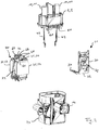
- Power relay 1 shown as a whole comprises a housing 2, which is formed from two parts, namely a terminal socket 3 and a housing pot 4. Both the terminal base 3 and the housing pot 4 are in this case formed as injection-molded plastic parts.
- the terminal base 3 limits the housing 2 to a terminal side, at which the power relay 1 can be contacted with an external load circuit.
- This connection side is hereinafter - regardless of the actual orientation of the power relay 1 in the enclosed space - also referred to as the top 5.
- the housing pot 4 encloses with four side walls 6 and a housing bottom 7, the remaining sides of an approximately cuboid housing interior 8 (FIGS. Fig. 10 ).
- the housing bottom 7 in this case closes off the housing 2 from an underside 9 facing away from the upper side 5 (wherein the term "lower side" is also used independently of the actual orientation of the power relay 1 in the enclosed space).
- a partition wall 12 is formed on the outside of the terminal base 3, which projects into the intermediate space formed between the terminal pin 10.
- the power relay 1 - turned on by making a housing-internal electrically conductive connection between the terminal pins 10 or - by disconnecting this electrically conductive connection - is turned off, are on the housing pot 4 more signal connections 13 formed, can be clamped against the corresponding external signal lines to the power relay 1.
- the signal lines serve to supply at least one electrical control signal to the power relay 1 and / or to output at least one electrical state signal by the power relay 1.
- the signal terminals 13 are in this case formed as contacts of a connector 14 which is integrally formed on the wall of the housing pot 4.
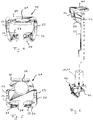
- Fig. 2 shows the power relay 1 in partially dismounted state. It can be seen from this representation that the power relay 1 is formed from four subassemblies which are in each case connected in one another. In addition to the housing parts already described, namely the terminal base 3 with the attached connecting bolt 10 and next to the housing pot 4 with the molded connector 14, the power relay 1 accordingly comprises a coil assembly 20 and a hereinafter referred to as board 21 line carrier.
- the coil assembly 20 comprises a contact bridge 22, which via a coupling rod 23 with a - hidden inside the coil assembly 20 and only in Fig. 10 visible - magnet armature 24 of a magnetic circuit is mechanically coupled.
- the magnetic circuit comprises a magnetic yoke 25, said magnetic yoke 25 by a central, the coupling rod 23 concentrically surrounding hollow cylindrical core 26, a U-shaped bent bracket 27 and two of the leg ends of the bracket converging pole pieces 28 (FIGS. Fig. 10 ) is formed.
- the pole pieces 28 in this case include the magnet armature 24 between them.
- the armature 24 and the components of the magnetic yoke 15 are formed of ferromagnetic material.
- the power relay 1 can be designed in particular as a bistable relay.
- the pole shoes 28 and the leg ends of the bracket 27 each one or more permanent magnets interposed.
- the permanent magnets are replaced by ferromagnetic material.
- the coil assembly 20 further includes a magnetic coil 29, which rests in the framed by the magnetic yoke 25 volume.
- the magnetic coil 29 in this case surrounds the core 26 of the magnetic yoke 25 concentrically and in turn is framed by the yoke 27 and the pole shoes 28.
- the board 21 is formed of two sections 30 and 31 which are hingedly connected to each other via a film hinge 32 and therefore from a plain initial state in the in Fig. 2 shown L-shaped arrangement are bendable.
- the portion 30 carries a control electronics 33.
- the section 31 includes mainly contact points for electrical contacting of the magnetic coil 29 and for contacting optionally existing electrical functional elements for coil extinction, switching position display, overtemperature shutdown, etc.
- the board 21 is preferably also present. However, it carries in this case, no control electronics 33, but only traces for contacting the solenoid 29 and the possibly existing electrical functional elements with the signal terminals 13. Alternatively, the board 21 is replaced with purely electromechanical designs of the power relay 1 by wire conductor.
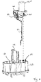
- Fig. 3 shows in an exploded view of the terminal base 3 with the connecting bolt 10 and other components of the power relay 1, which are fixed in the intended mounting state of the power relay 1 in the terminal socket 3.
- each of the two connecting bolts 10 is formed in each case by a standard screw with a hexagonal head 40.
- the connecting bolts 10 are here in particular standard screws in accordance with ISO 4017, in which the threaded shaft 11 is provided in each case with a metric thread reaching to the hexagonal head 40 (in particular M6, M8, M10 or M12).
- Each connection bolt 10 is assigned in each case a connection conductor 41, a filler 42 and an auxiliary conductor 43.
- the auxiliary conductors 41 serve in this case for electrical contacting of the associated connecting bolt 10 with the housing interior 8.
- each of the leads 41 is formed by a bent sheet metal stamping.
- Each of the connecting conductors 41 in this case comprises a tab-like shaped central portion 50, which is provided with a central bore 51 for receiving the threaded shaft 11 of the associated connecting bolt 10.
- At two opposite side edges of the central portion 50 each passes into a fixing leg 52.
- the two fixing legs 52 serve to fix the respective connection conductor 41 in the connection base 3.
- the fixing legs 52 are each bent approximately at right angles from the central section 50 and provided at their side edges, each with a sawtooth contour 53.
- each connecting conductor 41 has approximately the shape of a one-sided slotted frame or ring.
- the bent ends of the Fixierschenkel 52 are hereinafter referred to as contact ends 54.
- Each contact end 54 carries a pressed-contact element 55th
- the filler pieces 42 are injection molded components. Each filler 42 is formed on an outer side 56 such that it can be used with this outside 56 fit exactly in the encompassed by the associated terminal conductor 41 volume. On one of the outer side 56 opposite the inner side 57 a receptacle 58 is formed in each of the two filling pieces 42, in which the hexagon head 40 of the associated connecting bolt 10 with the formation of a positive fit or with little play with about half of its circumference can be used.
- the auxiliary conductors 43 are elongated, curved sheet-metal stamped parts.
- the mounting of the terminal bolts 10, the terminal conductor 41, the filler pieces 42 and the auxiliary conductor 43 in the terminal socket 3 is in the Fig. 6 and 7 shown schematically.
- one of the auxiliary conductors 43 is first welded or riveted on the inside opposite the contact element 55 on one of the contact ends 54 of an associated connecting conductor 41.
- one of the connecting bolts 10 with the hexagonal head 40 is inserted into the receptacle 48 of the associated one Filler 42.
- the terminal conductor 41 with the soldered auxiliary conductor 43 according to Fig.
- the Fig. 8 and 9 show the terminal socket 3 in the fully populated state.
- the connecting bolts 10 are each received with their hexagonal head 40 in a form-fitting and torsion-proof manner in the connection socket 3, so that the threaded shank 11 of the connection bolt 10 protrudes outwards towards the connection socket 3 in each case towards the upper side 5.
- the connection bolts 10 are hereby added loosely in the connection socket 3 and thus unconnected to the material of the connection socket 3.
- the connection bolts 10 are also slightly movable relative to the connection base 3. against loss, the connecting bolts 10 are secured in this case only by the respective associated connection conductor 41, which engages around the hexagon head 40 with the central portion 50 on the outside.
- connection conductors 41 protrude with their respective contact ends 54 into an underside of the housing base 3 into the housing interior 8.
- the corresponding moving contact of this main switching device forms the contact bridge 22 of the coil assembly 20, which for this purpose to each contact element 55 of the connecting conductor 41 a corresponding mating contact element 60th ( Fig. 2 ) having.
- connection socket 3 is on its underside with molded snap hooks 61 (FIG. Fig. 2 ), which engage on both sides under the bracket 27 of the magnetic yoke 25.
- the board 21 is mounted.
- the auxiliary conductors 43 and the coil terminals (not explicitly shown) of the magnet coil 29 are soldered to corresponding contact points on the section 31 of the board 21.
- the housing pot 4 is slipped over the coil assembly 20 and the board 21 and bolted to the terminal base 3, whereby the housing 2 is closed.
- a potting compound 65 (FIG. Fig. 1 and 10 ) shed.
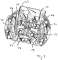
- Fig. 10 how out Fig. 10 it can be seen are in the assembled state of the power relay 1, the contact elements 55 of the connecting conductors 41 each in juxtaposition to a mating contact element 60 of the contact bridge 22.
- the mating contact elements 60 are electrically short inside the contact bridge 22.
- the contact ends 54 of the connection conductors 41 are angled away from the adjoining fixing legs 52 in such a way that they are inclined relative to the respectively associated central section 50, and thus also obliquely to a housing axis 66 of the power relay 1.
- the contact ends 54 thus together form a pitched roof-like structure.
- the attached to the housing interior 8 side facing the contact ends 54 mounted contact elements 55 are thereby inclined to each other.
- the contact bridge 22 has a V-shaped or roof-like structure with obliquely angled ends, so that the mating contact elements 60 are aligned parallel to the corresponding contact elements 55. Due to the inclination of the contact elements 55 and the corresponding mating contact elements 60 in this case a good contact closure of all four contact elements 55 is favored with the corresponding mating contact elements 60.
- Fig. 10 shows the power relay 1 in an open position in which the mating contact elements 60 of the contact elements 55 are lifted (deuttoniert), so that there is no electrically conductive connection between the terminal bolt 10.
- the solenoid 29 is energized.
- a magnetic flux is generated in the magnetic yoke 25, through which the magnet armature 24 is attracted against the core 26 of the magnetic yoke 25.
- the contact bridge 22 is deflected upwards, so that the mating contact elements 60 abut against the corresponding contact elements 55.
- the solenoid 29 is energized with reverse polarity. Under the effect of the magnetic flux generated in this case in the magnetic yoke 25, the holding force generated by the permanent magnets 29 is compensated, whereby the magnet armature 24 by a return spring 67 (FIG. Fig. 10 ) withdrawn from the core 26 and thus in the open position according to Fig. 10 is pressed.
- the magnet armature 24 in this case takes over the coupling rod 23, in turn, the contact bridge 22, whereby the counter contact elements 60 - are disconnected from the corresponding contact elements 55 - with separation of the electrical connection between the connecting pins 10.
- each of the two switching positions of the power relay 1 is stable even in the de-energized state of the solenoid 29.
- the solenoid 29 must be energized only temporarily.
- the board 21 is supplied with a supply voltage for the control electronics 33. Furthermore, the control electronics 33 determined in the on state of the power relay 1 based on tapped via the auxiliary conductor 43 potentials between the terminal pin 10 falling voltage as a measure of the current intensity of the current flowing through the power relay 1 load current to the power relay 1 in case of overload or short circuit automatically off.
Landscapes
- Physics & Mathematics (AREA)
- Electromagnetism (AREA)
- Engineering & Computer Science (AREA)
- Civil Engineering (AREA)
- Mechanical Engineering (AREA)
- Structural Engineering (AREA)
- Switch Cases, Indication, And Locking (AREA)
- Connection Or Junction Boxes (AREA)
Priority Applications (1)
| Application Number | Priority Date | Filing Date | Title |
|---|---|---|---|
| PL15727875T PL3146554T3 (pl) | 2014-05-21 | 2015-05-21 | Przekaźnik mocy dla pojazdu |
Applications Claiming Priority (2)
| Application Number | Priority Date | Filing Date | Title |
|---|---|---|---|
| DE102014007457.9A DE102014007457B3 (de) | 2014-05-21 | 2014-05-21 | Leistungsrelais für ein Fahrzeug |
| PCT/EP2015/001031 WO2015176817A1 (de) | 2014-05-21 | 2015-05-21 | Leistungsrelais für ein fahrzeug |
Publications (2)
| Publication Number | Publication Date |
|---|---|
| EP3146554A1 EP3146554A1 (de) | 2017-03-29 |
| EP3146554B1 true EP3146554B1 (de) | 2018-03-14 |
Family
ID=53373384
Family Applications (1)
| Application Number | Title | Priority Date | Filing Date |
|---|---|---|---|
| EP15727875.5A Active EP3146554B1 (de) | 2014-05-21 | 2015-05-21 | Leistungsrelais für ein fahrzeug |
Country Status (8)
| Country | Link |
|---|---|
| US (1) | US10249462B2 (pl) |
| EP (1) | EP3146554B1 (pl) |
| KR (1) | KR101912701B1 (pl) |
| CN (1) | CN106463282B (pl) |
| DE (2) | DE202014010575U1 (pl) |
| ES (1) | ES2670823T3 (pl) |
| PL (1) | PL3146554T3 (pl) |
| WO (1) | WO2015176817A1 (pl) |
Families Citing this family (3)
| Publication number | Priority date | Publication date | Assignee | Title |
|---|---|---|---|---|
| CN113782356B (zh) * | 2021-07-23 | 2023-06-16 | 宁波金宸科技有限公司 | 一种基于液压传动的继电器 |
| KR102592289B1 (ko) * | 2021-09-16 | 2023-10-19 | 엘에스일렉트릭(주) | 케이블 커넥터 |
| KR102640507B1 (ko) * | 2021-11-18 | 2024-02-23 | 엘에스일렉트릭(주) | 아크 경로 형성부 및 이를 포함하는 직류 릴레이 |
Family Cites Families (16)
| Publication number | Priority date | Publication date | Assignee | Title |
|---|---|---|---|---|
| US2496145A (en) * | 1948-02-05 | 1950-01-31 | Arrow Hart & Hegeman Electric | Wire terminal mounting |
| US3271702A (en) * | 1960-10-17 | 1966-09-06 | Andrew Corp | Coaxial transfer switch |
| FR2554988B1 (fr) | 1983-11-16 | 1988-05-06 | Telemecanique Electrique | Moteur pas a pas du type hybride polyphase et son dispositif de commande |
| US4595811A (en) * | 1985-08-29 | 1986-06-17 | Cooper Industries, Inc. | Switch contact element retaining means and method of assembly |
| US4969844A (en) * | 1988-10-06 | 1990-11-13 | Mitsubishi Denki Kabushiki Kaisha | Electromagnetic contector |
| IT216993Z2 (it) * | 1989-03-22 | 1991-10-21 | Magneti Marelli Spa | Dispositivo elettromagnetico di controllo dell alimentazione di corrente al motore elettrico di avviamen to di un motore a combustione interna |
| US5521566A (en) * | 1994-08-25 | 1996-05-28 | Clum Manufacturing Company, Inc. | High amperage solenoid structure |
| JP3210217B2 (ja) * | 1995-08-30 | 2001-09-17 | 株式会社ミツバ | 電磁スイッチにおけるターミナルハウジングの組付け構造 |
| JP3310208B2 (ja) * | 1998-01-23 | 2002-08-05 | 株式会社日立製作所 | ターミナルボルトの固定構造 |
| CZ296277B6 (cs) * | 2003-05-20 | 2006-02-15 | Magneton A.S. | Usporádání pohyblivého jádra elektromagnetu spínace spoustece spalovacích motoru s pripojením kontaktu svorkovnice a elektromotoru |
| JP4661721B2 (ja) * | 2006-07-26 | 2011-03-30 | 株式会社デンソー | スタータ |
| JP4631845B2 (ja) * | 2006-12-06 | 2011-02-16 | 株式会社デンソー | スタータ用電磁スイッチ |
| DE102008002098A1 (de) * | 2008-05-30 | 2009-12-03 | Robert Bosch Gmbh | Einrückrelais für Starter von Brennkraftmaschinen |
| DE102010018755A1 (de) * | 2010-04-29 | 2011-11-03 | Kissling Elektrotechnik Gmbh | Relais mit integrierter Sicherheitsbeschaltung |
| DE102010018738A1 (de) * | 2010-04-29 | 2011-11-03 | Kissling Elektrotechnik Gmbh | Bistabiles Relais |
| CN202150414U (zh) * | 2011-08-11 | 2012-02-22 | 慈溪奥博汽车电器有限公司 | 一种电磁开关 |
-
2014
- 2014-05-21 DE DE202014010575.8U patent/DE202014010575U1/de not_active Expired - Lifetime
- 2014-05-21 DE DE102014007457.9A patent/DE102014007457B3/de not_active Expired - Fee Related
-
2015
- 2015-05-21 CN CN201580025835.5A patent/CN106463282B/zh active Active
- 2015-05-21 WO PCT/EP2015/001031 patent/WO2015176817A1/de not_active Ceased
- 2015-05-21 PL PL15727875T patent/PL3146554T3/pl unknown
- 2015-05-21 ES ES15727875.5T patent/ES2670823T3/es active Active
- 2015-05-21 KR KR1020167035853A patent/KR101912701B1/ko not_active Expired - Fee Related
- 2015-05-21 EP EP15727875.5A patent/EP3146554B1/de active Active
-
2016
- 2016-11-21 US US15/357,181 patent/US10249462B2/en active Active
Also Published As
| Publication number | Publication date |
|---|---|
| CN106463282A (zh) | 2017-02-22 |
| DE102014007457B3 (de) | 2015-11-19 |
| US10249462B2 (en) | 2019-04-02 |
| CN106463282B (zh) | 2018-11-13 |
| KR101912701B1 (ko) | 2018-12-28 |
| PL3146554T3 (pl) | 2018-08-31 |
| EP3146554A1 (de) | 2017-03-29 |
| DE202014010575U1 (de) | 2016-01-07 |
| ES2670823T3 (es) | 2018-06-01 |
| US20170069451A1 (en) | 2017-03-09 |
| KR20170005869A (ko) | 2017-01-16 |
| WO2015176817A1 (de) | 2015-11-26 |
Similar Documents
| Publication | Publication Date | Title |
|---|---|---|
| EP3146553B1 (de) | Leistungsrelais für ein fahrzeug | |
| EP3086351B1 (de) | Leistungsrelais für ein fahrzeug | |
| DE3912873C2 (pl) | ||
| EP3146554B1 (de) | Leistungsrelais für ein fahrzeug | |
| EP3613110A1 (de) | Baugruppe für ein steckverbinderteil mit einem kontakteinsatz und einem erdungselement | |
| EP2720325B1 (de) | Schaltbare Steckdose | |
| WO2005083733A1 (de) | Schaltschütz mit anschlussmodul zum ansteuern des magnetantriebes | |
| AT505732B1 (de) | Netzspannungsversorgungsgerät | |
| DE1807319A1 (de) | Relais | |
| WO2007087788A2 (de) | Vorrichtung zum anschliessen wenigstens einer stromführenden leitung an einen batteriepol | |
| EP1548907A1 (de) | Anordnung zum Befestigen von elektrischen und/oder elektronischen Leistungsbauteilen an einer Platine und Gehäuse hiermit | |
| DE1901074B2 (de) | Elektrisches Schaltgerät oder Relais | |
| DE102013210193B4 (de) | Anordnung für ein elektrisches Schaltelement, insbesondere Schütz oder Relais, und elektrisches Schaltelement mit einem Steuerungsmodul zwischen Jochschenkel und Spule | |
| DE202015009124U1 (de) | Leistungsrelais für ein Fahrzeug | |
| DE102016110104A1 (de) | Steckdoseneinsatz | |
| DE202008012786U1 (de) | Steckverbinder | |
| EP1463393B1 (de) | Halbleiterrelais | |
| EP2846407A1 (de) | Kontaktbaugruppe für elektrische/elektronische Installationsgeräte | |
| EP0326118B1 (de) | Relais-Baugruppe mit Steckeranschlüssen | |
| DE1807319C (de) | Elektromagnetisches Relais | |
| DE2438084A1 (de) | Elektromagnetisches relais | |
| DE4439177A1 (de) | Elektromagnetischer Schalter, insbesondere Einrückrelais für Andrehvorrichtung von Brennkraftmaschinen | |
| EP1975962A1 (de) | Schaltgerät, insbesondere elektromagnetisches Schaltgerät | |
| DE19903636A1 (de) | Spannungsgesteuerte Schaltvorrichtung zum Einsatz im Kfz. | |
| EP0928512A1 (de) | Elektromotor, insbesondere wischermotor für kraftfahrzeuge |
Legal Events
| Date | Code | Title | Description |
|---|---|---|---|
| PUAI | Public reference made under article 153(3) epc to a published international application that has entered the european phase |
Free format text: ORIGINAL CODE: 0009012 |
|
| 17P | Request for examination filed |
Effective date: 20161202 |
|
| AK | Designated contracting states |
Kind code of ref document: A1 Designated state(s): AL AT BE BG CH CY CZ DE DK EE ES FI FR GB GR HR HU IE IS IT LI LT LU LV MC MK MT NL NO PL PT RO RS SE SI SK SM TR |
|
| AX | Request for extension of the european patent |
Extension state: BA ME |
|
| DAV | Request for validation of the european patent (deleted) | ||
| DAX | Request for extension of the european patent (deleted) | ||
| GRAP | Despatch of communication of intention to grant a patent |
Free format text: ORIGINAL CODE: EPIDOSNIGR1 |
|
| INTG | Intention to grant announced |
Effective date: 20171009 |
|
| GRAS | Grant fee paid |
Free format text: ORIGINAL CODE: EPIDOSNIGR3 |
|
| GRAA | (expected) grant |
Free format text: ORIGINAL CODE: 0009210 |
|
| AK | Designated contracting states |
Kind code of ref document: B1 Designated state(s): AL AT BE BG CH CY CZ DE DK EE ES FI FR GB GR HR HU IE IS IT LI LT LU LV MC MK MT NL NO PL PT RO RS SE SI SK SM TR |
|
| REG | Reference to a national code |
Ref country code: GB Ref legal event code: FG4D Free format text: NOT ENGLISH |
|
| REG | Reference to a national code |
Ref country code: CH Ref legal event code: EP Ref country code: AT Ref legal event code: REF Ref document number: 979622 Country of ref document: AT Kind code of ref document: T Effective date: 20180315 |
|
| REG | Reference to a national code |
Ref country code: IE Ref legal event code: FG4D Free format text: LANGUAGE OF EP DOCUMENT: GERMAN |
|
| REG | Reference to a national code |
Ref country code: DE Ref legal event code: R096 Ref document number: 502015003450 Country of ref document: DE |
|
| REG | Reference to a national code |
Ref country code: FR Ref legal event code: PLFP Year of fee payment: 4 |
|
| REG | Reference to a national code |
Ref country code: ES Ref legal event code: FG2A Ref document number: 2670823 Country of ref document: ES Kind code of ref document: T3 Effective date: 20180601 |
|
| REG | Reference to a national code |
Ref country code: SE Ref legal event code: TRGR |
|
| REG | Reference to a national code |
Ref country code: NL Ref legal event code: FP |
|
| REG | Reference to a national code |
Ref country code: LT Ref legal event code: MG4D |
|
| PG25 | Lapsed in a contracting state [announced via postgrant information from national office to epo] |
Ref country code: LT Free format text: LAPSE BECAUSE OF FAILURE TO SUBMIT A TRANSLATION OF THE DESCRIPTION OR TO PAY THE FEE WITHIN THE PRESCRIBED TIME-LIMIT Effective date: 20180314 Ref country code: CY Free format text: LAPSE BECAUSE OF FAILURE TO SUBMIT A TRANSLATION OF THE DESCRIPTION OR TO PAY THE FEE WITHIN THE PRESCRIBED TIME-LIMIT Effective date: 20180314 Ref country code: HR Free format text: LAPSE BECAUSE OF FAILURE TO SUBMIT A TRANSLATION OF THE DESCRIPTION OR TO PAY THE FEE WITHIN THE PRESCRIBED TIME-LIMIT Effective date: 20180314 Ref country code: NO Free format text: LAPSE BECAUSE OF FAILURE TO SUBMIT A TRANSLATION OF THE DESCRIPTION OR TO PAY THE FEE WITHIN THE PRESCRIBED TIME-LIMIT Effective date: 20180614 Ref country code: FI Free format text: LAPSE BECAUSE OF FAILURE TO SUBMIT A TRANSLATION OF THE DESCRIPTION OR TO PAY THE FEE WITHIN THE PRESCRIBED TIME-LIMIT Effective date: 20180314 |
|
| PG25 | Lapsed in a contracting state [announced via postgrant information from national office to epo] |
Ref country code: RS Free format text: LAPSE BECAUSE OF FAILURE TO SUBMIT A TRANSLATION OF THE DESCRIPTION OR TO PAY THE FEE WITHIN THE PRESCRIBED TIME-LIMIT Effective date: 20180314 Ref country code: LV Free format text: LAPSE BECAUSE OF FAILURE TO SUBMIT A TRANSLATION OF THE DESCRIPTION OR TO PAY THE FEE WITHIN THE PRESCRIBED TIME-LIMIT Effective date: 20180314 Ref country code: BG Free format text: LAPSE BECAUSE OF FAILURE TO SUBMIT A TRANSLATION OF THE DESCRIPTION OR TO PAY THE FEE WITHIN THE PRESCRIBED TIME-LIMIT Effective date: 20180614 Ref country code: GR Free format text: LAPSE BECAUSE OF FAILURE TO SUBMIT A TRANSLATION OF THE DESCRIPTION OR TO PAY THE FEE WITHIN THE PRESCRIBED TIME-LIMIT Effective date: 20180615 |
|
| PG25 | Lapsed in a contracting state [announced via postgrant information from national office to epo] |
Ref country code: MT Free format text: LAPSE BECAUSE OF FAILURE TO SUBMIT A TRANSLATION OF THE DESCRIPTION OR TO PAY THE FEE WITHIN THE PRESCRIBED TIME-LIMIT Effective date: 20180314 |
|
| PG25 | Lapsed in a contracting state [announced via postgrant information from national office to epo] |
Ref country code: EE Free format text: LAPSE BECAUSE OF FAILURE TO SUBMIT A TRANSLATION OF THE DESCRIPTION OR TO PAY THE FEE WITHIN THE PRESCRIBED TIME-LIMIT Effective date: 20180314 Ref country code: RO Free format text: LAPSE BECAUSE OF FAILURE TO SUBMIT A TRANSLATION OF THE DESCRIPTION OR TO PAY THE FEE WITHIN THE PRESCRIBED TIME-LIMIT Effective date: 20180314 Ref country code: IT Free format text: LAPSE BECAUSE OF FAILURE TO SUBMIT A TRANSLATION OF THE DESCRIPTION OR TO PAY THE FEE WITHIN THE PRESCRIBED TIME-LIMIT Effective date: 20180314 Ref country code: AL Free format text: LAPSE BECAUSE OF FAILURE TO SUBMIT A TRANSLATION OF THE DESCRIPTION OR TO PAY THE FEE WITHIN THE PRESCRIBED TIME-LIMIT Effective date: 20180314 |
|
| PG25 | Lapsed in a contracting state [announced via postgrant information from national office to epo] |
Ref country code: SK Free format text: LAPSE BECAUSE OF FAILURE TO SUBMIT A TRANSLATION OF THE DESCRIPTION OR TO PAY THE FEE WITHIN THE PRESCRIBED TIME-LIMIT Effective date: 20180314 Ref country code: SM Free format text: LAPSE BECAUSE OF FAILURE TO SUBMIT A TRANSLATION OF THE DESCRIPTION OR TO PAY THE FEE WITHIN THE PRESCRIBED TIME-LIMIT Effective date: 20180314 Ref country code: CZ Free format text: LAPSE BECAUSE OF FAILURE TO SUBMIT A TRANSLATION OF THE DESCRIPTION OR TO PAY THE FEE WITHIN THE PRESCRIBED TIME-LIMIT Effective date: 20180314 |
|
| REG | Reference to a national code |
Ref country code: CH Ref legal event code: PL |
|
| REG | Reference to a national code |
Ref country code: DE Ref legal event code: R097 Ref document number: 502015003450 Country of ref document: DE |
|
| PG25 | Lapsed in a contracting state [announced via postgrant information from national office to epo] |
Ref country code: PT Free format text: LAPSE BECAUSE OF FAILURE TO SUBMIT A TRANSLATION OF THE DESCRIPTION OR TO PAY THE FEE WITHIN THE PRESCRIBED TIME-LIMIT Effective date: 20180716 |
|
| PLBE | No opposition filed within time limit |
Free format text: ORIGINAL CODE: 0009261 |
|
| STAA | Information on the status of an ep patent application or granted ep patent |
Free format text: STATUS: NO OPPOSITION FILED WITHIN TIME LIMIT |
|
| REG | Reference to a national code |
Ref country code: BE Ref legal event code: MM Effective date: 20180531 |
|
| PG25 | Lapsed in a contracting state [announced via postgrant information from national office to epo] |
Ref country code: MC Free format text: LAPSE BECAUSE OF FAILURE TO SUBMIT A TRANSLATION OF THE DESCRIPTION OR TO PAY THE FEE WITHIN THE PRESCRIBED TIME-LIMIT Effective date: 20180314 Ref country code: DK Free format text: LAPSE BECAUSE OF FAILURE TO SUBMIT A TRANSLATION OF THE DESCRIPTION OR TO PAY THE FEE WITHIN THE PRESCRIBED TIME-LIMIT Effective date: 20180314 |
|
| 26N | No opposition filed |
Effective date: 20181217 |
|
| REG | Reference to a national code |
Ref country code: IE Ref legal event code: MM4A |
|
| PG25 | Lapsed in a contracting state [announced via postgrant information from national office to epo] |
Ref country code: CH Free format text: LAPSE BECAUSE OF NON-PAYMENT OF DUE FEES Effective date: 20180531 Ref country code: SI Free format text: LAPSE BECAUSE OF FAILURE TO SUBMIT A TRANSLATION OF THE DESCRIPTION OR TO PAY THE FEE WITHIN THE PRESCRIBED TIME-LIMIT Effective date: 20180314 Ref country code: LI Free format text: LAPSE BECAUSE OF NON-PAYMENT OF DUE FEES Effective date: 20180531 |
|
| PG25 | Lapsed in a contracting state [announced via postgrant information from national office to epo] |
Ref country code: LU Free format text: LAPSE BECAUSE OF NON-PAYMENT OF DUE FEES Effective date: 20180521 |
|
| PG25 | Lapsed in a contracting state [announced via postgrant information from national office to epo] |
Ref country code: IE Free format text: LAPSE BECAUSE OF NON-PAYMENT OF DUE FEES Effective date: 20180521 |
|
| PG25 | Lapsed in a contracting state [announced via postgrant information from national office to epo] |
Ref country code: BE Free format text: LAPSE BECAUSE OF NON-PAYMENT OF DUE FEES Effective date: 20180531 |
|
| PG25 | Lapsed in a contracting state [announced via postgrant information from national office to epo] |
Ref country code: TR Free format text: LAPSE BECAUSE OF FAILURE TO SUBMIT A TRANSLATION OF THE DESCRIPTION OR TO PAY THE FEE WITHIN THE PRESCRIBED TIME-LIMIT Effective date: 20180314 |
|
| PG25 | Lapsed in a contracting state [announced via postgrant information from national office to epo] |
Ref country code: MK Free format text: LAPSE BECAUSE OF NON-PAYMENT OF DUE FEES Effective date: 20180314 Ref country code: HU Free format text: LAPSE BECAUSE OF FAILURE TO SUBMIT A TRANSLATION OF THE DESCRIPTION OR TO PAY THE FEE WITHIN THE PRESCRIBED TIME-LIMIT; INVALID AB INITIO Effective date: 20150521 |
|
| PG25 | Lapsed in a contracting state [announced via postgrant information from national office to epo] |
Ref country code: IS Free format text: LAPSE BECAUSE OF FAILURE TO SUBMIT A TRANSLATION OF THE DESCRIPTION OR TO PAY THE FEE WITHIN THE PRESCRIBED TIME-LIMIT Effective date: 20180714 |
|
| PGFP | Annual fee paid to national office [announced via postgrant information from national office to epo] |
Ref country code: AT Payment date: 20200515 Year of fee payment: 6 |
|
| REG | Reference to a national code |
Ref country code: AT Ref legal event code: MM01 Ref document number: 979622 Country of ref document: AT Kind code of ref document: T Effective date: 20210521 |
|
| PG25 | Lapsed in a contracting state [announced via postgrant information from national office to epo] |
Ref country code: AT Free format text: LAPSE BECAUSE OF NON-PAYMENT OF DUE FEES Effective date: 20210521 |
|
| PGFP | Annual fee paid to national office [announced via postgrant information from national office to epo] |
Ref country code: PL Payment date: 20230511 Year of fee payment: 9 |
|
| P01 | Opt-out of the competence of the unified patent court (upc) registered |
Effective date: 20231120 |
|
| PGFP | Annual fee paid to national office [announced via postgrant information from national office to epo] |
Ref country code: NL Payment date: 20250522 Year of fee payment: 11 |
|
| PG25 | Lapsed in a contracting state [announced via postgrant information from national office to epo] |
Ref country code: PL Free format text: LAPSE BECAUSE OF NON-PAYMENT OF DUE FEES Effective date: 20240521 |
|
| PGFP | Annual fee paid to national office [announced via postgrant information from national office to epo] |
Ref country code: DE Payment date: 20250528 Year of fee payment: 11 |
|
| PGFP | Annual fee paid to national office [announced via postgrant information from national office to epo] |
Ref country code: ES Payment date: 20250616 Year of fee payment: 11 Ref country code: GB Payment date: 20250522 Year of fee payment: 11 |
|
| PGFP | Annual fee paid to national office [announced via postgrant information from national office to epo] |
Ref country code: FR Payment date: 20250521 Year of fee payment: 11 |
|
| PGFP | Annual fee paid to national office [announced via postgrant information from national office to epo] |
Ref country code: SE Payment date: 20250522 Year of fee payment: 11 |