EP3146270B1 - Vorrichtung und verfahren zum wiederholten erzeugen von explosionen zum antrieb eines luftfahrzeuges - Google Patents
Vorrichtung und verfahren zum wiederholten erzeugen von explosionen zum antrieb eines luftfahrzeuges Download PDFInfo
- Publication number
- EP3146270B1 EP3146270B1 EP15724927.7A EP15724927A EP3146270B1 EP 3146270 B1 EP3146270 B1 EP 3146270B1 EP 15724927 A EP15724927 A EP 15724927A EP 3146270 B1 EP3146270 B1 EP 3146270B1
- Authority
- EP
- European Patent Office
- Prior art keywords
- control valve
- nozzle
- explosion
- discharge opening
- area
- Prior art date
- Legal status (The legal status is an assumption and is not a legal conclusion. Google has not performed a legal analysis and makes no representation as to the accuracy of the status listed.)
- Active
Links
Images

Classifications
-
- F—MECHANICAL ENGINEERING; LIGHTING; HEATING; WEAPONS; BLASTING
- F02—COMBUSTION ENGINES; HOT-GAS OR COMBUSTION-PRODUCT ENGINE PLANTS
- F02K—JET-PROPULSION PLANTS
- F02K7/00—Plants in which the working fluid is used in a jet only, i.e. the plants not having a turbine or other engine driving a compressor or a ducted fan; Control thereof
- F02K7/02—Plants in which the working fluid is used in a jet only, i.e. the plants not having a turbine or other engine driving a compressor or a ducted fan; Control thereof the jet being intermittent, i.e. pulse-jet
- F02K7/06—Plants in which the working fluid is used in a jet only, i.e. the plants not having a turbine or other engine driving a compressor or a ducted fan; Control thereof the jet being intermittent, i.e. pulse-jet with combustion chambers having valves
-
- F—MECHANICAL ENGINEERING; LIGHTING; HEATING; WEAPONS; BLASTING
- F02—COMBUSTION ENGINES; HOT-GAS OR COMBUSTION-PRODUCT ENGINE PLANTS
- F02K—JET-PROPULSION PLANTS
- F02K1/00—Plants characterised by the form or arrangement of the jet pipe or nozzle; Jet pipes or nozzles peculiar thereto
- F02K1/06—Varying effective area of jet pipe or nozzle
- F02K1/08—Varying effective area of jet pipe or nozzle by axially moving or transversely deforming an internal member, e.g. the exhaust cone
-
- F—MECHANICAL ENGINEERING; LIGHTING; HEATING; WEAPONS; BLASTING
- F02—COMBUSTION ENGINES; HOT-GAS OR COMBUSTION-PRODUCT ENGINE PLANTS
- F02K—JET-PROPULSION PLANTS
- F02K1/00—Plants characterised by the form or arrangement of the jet pipe or nozzle; Jet pipes or nozzles peculiar thereto
- F02K1/06—Varying effective area of jet pipe or nozzle
- F02K1/15—Control or regulation
-
- F—MECHANICAL ENGINEERING; LIGHTING; HEATING; WEAPONS; BLASTING
- F02—COMBUSTION ENGINES; HOT-GAS OR COMBUSTION-PRODUCT ENGINE PLANTS
- F02K—JET-PROPULSION PLANTS
- F02K7/00—Plants in which the working fluid is used in a jet only, i.e. the plants not having a turbine or other engine driving a compressor or a ducted fan; Control thereof
- F02K7/02—Plants in which the working fluid is used in a jet only, i.e. the plants not having a turbine or other engine driving a compressor or a ducted fan; Control thereof the jet being intermittent, i.e. pulse-jet
-
- F—MECHANICAL ENGINEERING; LIGHTING; HEATING; WEAPONS; BLASTING
- F02—COMBUSTION ENGINES; HOT-GAS OR COMBUSTION-PRODUCT ENGINE PLANTS
- F02K—JET-PROPULSION PLANTS
- F02K9/00—Rocket-engine plants, i.e. plants carrying both fuel and oxidant therefor; Control thereof
- F02K9/42—Rocket-engine plants, i.e. plants carrying both fuel and oxidant therefor; Control thereof using liquid or gaseous propellants
- F02K9/44—Feeding propellants
-
- F—MECHANICAL ENGINEERING; LIGHTING; HEATING; WEAPONS; BLASTING
- F02—COMBUSTION ENGINES; HOT-GAS OR COMBUSTION-PRODUCT ENGINE PLANTS
- F02K—JET-PROPULSION PLANTS
- F02K9/00—Rocket-engine plants, i.e. plants carrying both fuel and oxidant therefor; Control thereof
- F02K9/42—Rocket-engine plants, i.e. plants carrying both fuel and oxidant therefor; Control thereof using liquid or gaseous propellants
- F02K9/44—Feeding propellants
- F02K9/52—Injectors
-
- F—MECHANICAL ENGINEERING; LIGHTING; HEATING; WEAPONS; BLASTING
- F02—COMBUSTION ENGINES; HOT-GAS OR COMBUSTION-PRODUCT ENGINE PLANTS
- F02K—JET-PROPULSION PLANTS
- F02K9/00—Rocket-engine plants, i.e. plants carrying both fuel and oxidant therefor; Control thereof
- F02K9/42—Rocket-engine plants, i.e. plants carrying both fuel and oxidant therefor; Control thereof using liquid or gaseous propellants
- F02K9/44—Feeding propellants
- F02K9/56—Control
- F02K9/58—Propellant feed valves
-
- F—MECHANICAL ENGINEERING; LIGHTING; HEATING; WEAPONS; BLASTING
- F02—COMBUSTION ENGINES; HOT-GAS OR COMBUSTION-PRODUCT ENGINE PLANTS
- F02K—JET-PROPULSION PLANTS
- F02K9/00—Rocket-engine plants, i.e. plants carrying both fuel and oxidant therefor; Control thereof
- F02K9/80—Rocket-engine plants, i.e. plants carrying both fuel and oxidant therefor; Control thereof characterised by thrust or thrust vector control
- F02K9/86—Rocket-engine plants, i.e. plants carrying both fuel and oxidant therefor; Control thereof characterised by thrust or thrust vector control using nozzle throats of adjustable cross- section
-
- F—MECHANICAL ENGINEERING; LIGHTING; HEATING; WEAPONS; BLASTING
- F02—COMBUSTION ENGINES; HOT-GAS OR COMBUSTION-PRODUCT ENGINE PLANTS
- F02K—JET-PROPULSION PLANTS
- F02K9/00—Rocket-engine plants, i.e. plants carrying both fuel and oxidant therefor; Control thereof
- F02K9/97—Rocket nozzles
-
- F—MECHANICAL ENGINEERING; LIGHTING; HEATING; WEAPONS; BLASTING
- F23—COMBUSTION APPARATUS; COMBUSTION PROCESSES
- F23R—GENERATING COMBUSTION PRODUCTS OF HIGH PRESSURE OR HIGH VELOCITY, e.g. GAS-TURBINE COMBUSTION CHAMBERS
- F23R7/00—Intermittent or explosive combustion chambers
-
- F—MECHANICAL ENGINEERING; LIGHTING; HEATING; WEAPONS; BLASTING
- F02—COMBUSTION ENGINES; HOT-GAS OR COMBUSTION-PRODUCT ENGINE PLANTS
- F02B—INTERNAL-COMBUSTION PISTON ENGINES; COMBUSTION ENGINES IN GENERAL
- F02B71/00—Free-piston engines; Engines without rotary main shaft
- F02B71/04—Adaptations of such engines for special use; Combinations of such engines with apparatus driven thereby
- F02B71/06—Free-piston combustion gas generators per se
-
- F—MECHANICAL ENGINEERING; LIGHTING; HEATING; WEAPONS; BLASTING
- F05—INDEXING SCHEMES RELATING TO ENGINES OR PUMPS IN VARIOUS SUBCLASSES OF CLASSES F01-F04
- F05D—INDEXING SCHEME FOR ASPECTS RELATING TO NON-POSITIVE-DISPLACEMENT MACHINES OR ENGINES, GAS-TURBINES OR JET-PROPULSION PLANTS
- F05D2220/00—Application
- F05D2220/30—Application in turbines
- F05D2220/32—Application in turbines in gas turbines
- F05D2220/323—Application in turbines in gas turbines for aircraft propulsion, e.g. jet engines
-
- F—MECHANICAL ENGINEERING; LIGHTING; HEATING; WEAPONS; BLASTING
- F05—INDEXING SCHEMES RELATING TO ENGINES OR PUMPS IN VARIOUS SUBCLASSES OF CLASSES F01-F04
- F05D—INDEXING SCHEME FOR ASPECTS RELATING TO NON-POSITIVE-DISPLACEMENT MACHINES OR ENGINES, GAS-TURBINES OR JET-PROPULSION PLANTS
- F05D2220/00—Application
- F05D2220/80—Application in supersonic vehicles excluding hypersonic vehicles or ram, scram or rocket propulsion
-
- F—MECHANICAL ENGINEERING; LIGHTING; HEATING; WEAPONS; BLASTING
- F05—INDEXING SCHEMES RELATING TO ENGINES OR PUMPS IN VARIOUS SUBCLASSES OF CLASSES F01-F04
- F05D—INDEXING SCHEME FOR ASPECTS RELATING TO NON-POSITIVE-DISPLACEMENT MACHINES OR ENGINES, GAS-TURBINES OR JET-PROPULSION PLANTS
- F05D2240/00—Components
- F05D2240/35—Combustors or associated equipment
-
- F—MECHANICAL ENGINEERING; LIGHTING; HEATING; WEAPONS; BLASTING
- F05—INDEXING SCHEMES RELATING TO ENGINES OR PUMPS IN VARIOUS SUBCLASSES OF CLASSES F01-F04
- F05D—INDEXING SCHEME FOR ASPECTS RELATING TO NON-POSITIVE-DISPLACEMENT MACHINES OR ENGINES, GAS-TURBINES OR JET-PROPULSION PLANTS
- F05D2250/00—Geometry
- F05D2250/40—Movement of components
- F05D2250/41—Movement of components with one degree of freedom
Definitions
- the invention relates to a device and a method for repeatedly generating explosions for generating thrust, in particular in aircraft.
- Pulse Detonation Engines in which, instead of continuous combustion under constant pressure, the increase in temperature and pressure of isochoric combustion under constant volume, ie by explosions, is used.
- the explosion engine in which the pressure generated directly drives the piston, the kinetic energy of the exhausted combustion gases is maximized strived for.
- the smoke gases generated during the explosion should therefore be accelerated to maximum speed in order to generate maximum thrust and used for propulsion purposes.
- the Holzwarth turbine and pulse jet engines which generated thrust at high frequency by means of explosions became known.
- US 7,062,901 shows according to one embodiment ( Fig. 4 ) a single detonation chamber, and a nozzle with a flexible side wall.
- An exit area and / or an entry area of the nozzle should be variable by means of a control cam.
- the aim is to ensure optimal expansion.
- an explosion chamber is filled with an explosive gas under atmospheric pressure and this is ignited. So there is no pressure increase before ignition.
- EP 2 319 036 A2 (And also US 2011/180020 A1 ) describes a method for generating pressure pulses by means of explosions.
- a mixture of oxidizing agent and fuel is ignited in a container closed by a valve and an explosion is generated.
- the valve is opened shortly before ignition and the pressure wave of the explosion can be directed to its destination via the outlet opening.
- the device also known as an explosion generator (EG), is used today for cleaning dirty steam boilers.
- U.S. 5,797,260 and the one derived from it U.S. 5,941,062 describe a pulsating drive with a moving piston.
- the pressure of a supplied fuel moves the piston in the direction of a nozzle, thereby opening a feed to an injection chamber, which is separated from a combustion chamber by the piston.
- the fuel is catalytically converted through injection channels in the piston and a catalytic bed and then reaches the Combustion chamber and ignites.
- the resulting explosion moves the piston back away from the nozzle.
- fuel is increasingly driven through the injection channels, in particular after the feed has been closed again, as a result of which the pressure in the combustion chamber rises sharply.
- the cycle can repeat itself.
- a projection of the piston can close the nozzle neck to a greater or lesser extent. This means that the operation of the drive can be optimized, but no further information is given on this.
- US 2008/098711 A1 shows a rocket motor with a constant volume combustion process in pulse mode operation. An exhaust valve of the combustion chamber is opened when the combustion chamber pressure is maximum.
- One object of the invention is to create a device and a method of the type mentioned at the beginning which bring about an improved conversion of the energy released during the explosion into kinetic energy of the flue gas.
- the device is used to repeatedly generate explosions. It has: an explosion chamber, a supply line for supplying a flowable explosive material, a discharge opening for the directional discharge of a gas pressure generated by ignition of the explosive material in the explosion chamber, and a movable closure element for partially or completely closing the discharge opening.
- the device has an outlet nozzle with a nozzle inlet surface and a nozzle outlet surface, as well as an actuating device.
- the setting device is designed to set an area ratio between the nozzle inlet area and the nozzle outlet area after the discharge opening has opened and explosion gases flow out through the outlet nozzle, which area ratio follows at least approximately an ideal area ratio for generating a maximum exit speed of the explosion gases depending on the pressure in the explosion space.
- a pressure in the explosion chamber can be increased before ignition.
- the pressure generated during the explosion is proportional to the pressure before ignition.
- the invention realizes a nozzle, in particular a convergent-divergent one, which ensures that the optimal, ideal area ratio between the nozzle end (nozzle exit area) and nozzle neck (nozzle entry area) is always at least approximately set during the entire outflow time.
- a flowable, explosive substance or a flowable, explosive mixture which is formed by mixing preferably non-explosive components, is introduced into the explosion chamber.
- the flowable substances and / or mixtures of substances are, for example, gaseous, liquid, powdery, dusty or powdery or a mixture of such component substances.
- one component is a fuel and another component is an oxidizer.
- a mixture consists of two gases under pressure.
- a convergent-divergent nozzle (Laval nozzle) can be used.
- the flow speed is accelerated from subsonic in the explosion chamber to the speed of sound in the narrowest cross-section (the nozzle throat) and to supersonic speed in the divergent part of the nozzle along a stream filament.
- the nozzle cross-section is continuously expanded.
- the pressure also drops continuously to the end of the nozzle.
- p c is the combustion chamber pressure in the explosion chamber or nozzle inlet pressure
- p e the pressure at the nozzle end or nozzle outlet pressure
- a e the nozzle outlet area
- a t the nozzle inlet area
- isentropic exponent the isentropic exponent
- the area ratio E should also decrease.
- the explosion of a stoichiometric mixture of air and hydrogen under, for example, 20 bar pre-pressure at 300 ° K results in a maximum combustion temperature of approx. 2400 ° C and an explosion pressure of approx. 150 bar.
- the pressure in the explosion space drops until the pressure is equalized with the surroundings.
- the ideal area ratio ⁇ should therefore ideally be reduced continuously from a maximum of 15 to approx. 2 according to the above formula, i.e. the nozzle area ratio should ideally be able to be varied by a factor of 7.5.
- the nozzle for example a convergent-divergent nozzle, should therefore ensure that at least approximately the optimal, ideal area ratio between nozzle end and nozzle neck is set during the entire outflow time.
- the outflow from the explosion volume of a pulse or explosion generator takes a few milliseconds at the most, i.e. the nozzle geometry must be able to be adjusted very quickly according to the outflow speed and explosion frequency.
- the aim is to achieve high specific generator outputs and to achieve this, high explosion frequencies are required, i.e. frequencies of up to 50 Hz are aimed for.
- a nozzle that is too short with an area ratio ⁇ that is too small gives up energy because the maximum exit speed is not reached. Too long a nozzle with too large an area ratio ⁇ leads to over-expansion and the thrust is slowed down by the counter pressure. In principle, there is exactly one optimal area ratio E for the given combustion chamber and ambient pressures.
- this object is achieved by an annular nozzle with a tubular outer part and a concentric, essentially conical inner part, which can be adjusted relative to one another in the axial direction. Its contour forms at least approximately an ideal Laval nozzle at any time during the outflow.
- An outer geometry of the nozzle with the neck and outlet diameter is preferably determined beforehand and designed for the maximum achievable thrust.
- the concentric inner part of the nozzle is movable and changes the nozzle throat area or nozzle inlet area at least approximately in accordance with the ideal area ratio.
- convergent-divergent nozzle shapes There are different convergent-divergent nozzle shapes. For example, a conical nozzle and a bell nozzle are common.
- a control valve is arranged to vary the nozzle inlet area
- the adjusting device is a control valve drive which controls a movement of the control valve to adjust the nozzle inlet area at least approximately in accordance with the ideal area ratio mentioned.
- the desired area ratio is thus achieved by varying the nozzle inlet area.
- the control valve can be moved along a longitudinal axis of the outlet nozzle by means of an axial movement.
- the outlet nozzle can be shaped essentially rotationally symmetrically; an axis of symmetry of this rotational symmetry is equal to the longitudinal axis.
- control valve has a control valve needle, and the nozzle inlet area is determined by the position of the control valve needle with respect to the outlet opening.
- control valve needle has an outer contour that tapers towards a valve tip, in particular an at least approximately conical outer contour.
- control valve and a valve seat form a convergent-divergent part of the outlet nozzle.
- the actuating device has a drive means for driving an opening movement of the control valve, in particular in that the drive means is implemented by an auxiliary explosion device in which an auxiliary explosion generates a force which supports the opening movement.
- Another force or force component that supports the opening movement can arise from the recoil of the escaping explosion gases against the control valve.
- the actuating device has a braking means for delaying an opening movement of the control valve, in particular in that the braking means is implemented by a gas pressure spring or by a camshaft or by a gas pressure spring in combination with a camshaft.
- Drive means and braking means can also be implemented by a single device, for example by a crank drive.
- a flywheel can be present to compensate for a rotary movement of the camshaft or the crank drive.
- the closure element is set up to temporarily completely close the drain opening. This makes it possible to increase the pressure in the explosion space above the ambient pressure before ignition.
- control valve acts as a closure element for partially or completely closing the drain opening. This enables a simple construction with few moving parts.
- a closing valve which acts in addition to the control valve and which acts as a closing element for partially or completely closing the drain opening. In this way, the control valve can be protected from wear.
- a closing valve drive for driving and / or braking the closing valve can be designed in the same way as one of the described embodiments for the control valve drive.
- the closing valve can be moved along the longitudinal axis of the outlet nozzle by means of an axial movement.
- control valve and the closing valve are arranged concentrically to one another.
- the closing valve can, for example, enclose the control valve and form a ring valve in the area of the discharge opening. This creates a strong thermal and mechanical stress absorbed by the closing valve and not by the control valve.
- the area ratio is achieved by varying the nozzle exit area. This can be done by varying the shape or the contour of the nozzle over time, synchronously with the repeated explosions.
- this is done by moving the outlet nozzle or a part of the outlet nozzle relative to the control valve, in particular relative to the tapering part of the control valve, that is to say the control valve needle.
- a device according to at least one of the preceding embodiments, wherein an adjustable nozzle part is arranged to vary the nozzle outlet area, and a nozzle adjustment device is set up to move the adjustable nozzle part to adjust the nozzle outlet area at least approximately in accordance with the aforementioned ideal area ratio steer.
- the adjustable nozzle part can be displaced in the axial direction relative to the control valve.
- the nozzle adjustment device can be implemented in the same way as one of the embodiments of control valve drives or shut-off valve drives described here.
- the change in the nozzle entry area is coordinated with that of the nozzle exit area.
- the step of opening the vent takes place before the step of igniting.
- a delayed ignition reduces thermal stress on the valve seat.
- the opening takes place, depending on the embodiment, by opening the control valve or the closing valve.
- the delay between the opening of the discharge opening (for example due to an auxiliary explosion to drive the corresponding valve) and the ignition in the explosion chamber is typically in the range of fractions of milliseconds to a few milliseconds, for example between 0.1 and 10 milliseconds, e.g. between 0.5 and 1 millisecond.
- the explosive material is ignited in the explosion space by conducting an explosion from an auxiliary explosion device through a line to the explosion room.
- an explosion from an auxiliary explosion device through a line to the explosion room.
- DDT deflagration-Detonation-Time
- a transition from deflagration to detonation can take a long time and is dependent on the ignition energy. If the main explosion is ignited directly with a spark plug, it could happen that no detonation at all with a sharp rise in pressure can be generated in the explosion chamber, or that the DDT takes too long and a large part of the compressed gases have already left the explosion chamber before the main explosion developed .
- auxiliary explosion device with, for example, a pre-explosion chamber
- the explosion or ignition is transmitted to the explosion chamber with a line (pipe) of the ignition
- the energy introduced in the explosion chamber is many times higher than with the spark plug and a detonation takes place reliably.
- the auxiliary explosion device can only be used in the manner described for ignition in the explosion chamber, or it can also serve as a drive or part of the drive of the control valve or the closing valve.
- Figure 1 shows a device for repeatedly generating explosions: an explosion space 11 can be filled with a flowable explosive material, for example an explosive gas mixture, via a feed line 16 with a filling valve 18.
- the material can be ignited with an ignition device 19, for example a spark plug, and made to explode.
- the material in the explosion chamber 11 is ignited via a line or delay line 232 also filled with explosive material by an explosion emanating from an auxiliary explosion chamber of an auxiliary explosion device 231 and guided through the delay line 232.
- the outlet nozzle 15 is a Laval nozzle, with a convergent nozzle section 151, an adjustable divergent nozzle section 152 and a fixed divergent nozzle section 153.
- the adjustability of the adjustable divergent nozzle section 152 is realized by an axially (that is, along a longitudinal axis of the outlet nozzle 15) adjustable control valve 21 with a control valve needle 22.
- the control valve needle 22 is arranged in the area of the adjustable divergent nozzle section 152 and is tapered, for example conical.
- the nozzle area in the area of the control valve needle 22 increases in the direction of the nozzle outlet area 14, corresponding to the decrease in a cross section of the control valve needle 22.
- the control valve 21 closes on a valve seat 12 the discharge opening 17 completely or at least approximately completely.
- the control valve 21 can thus also serve as a closing valve.
- the cross section of the nozzle increases over time at every location of the adjustable divergent nozzle section 152 and in the area of the discharge opening 17.
- a nozzle throat area or nozzle inlet area 13 in the area of the outlet opening 17 increases over time.
- the control valve 21 While the explosion space 11 is being filled with an explosive mixture of oxidizer and fuel, the control valve 21 seals off the explosion space 11 from the outlet nozzle 15. As a result, an overpressure can be generated, with which a high explosion pressure can in turn be generated.
- FIG Figure 2 shows an embodiment with a separate closing valve 31 and control valve 21.
- the other elements are the same as in FIG Figure 1 .
- This variant is useful if the closing valve 31 is to be moved very quickly independently of the Laval valve or control valve 21. This is particularly the case when the control valve 21 is driven with the aid of an auxiliary explosive device 231, for example as in FIG EP 2 319 036 A2 described.
- the closing valve 31 can be moved separately from the control valve 21.
- a closing valve drive 33 of the closing valve 31 can be designed analogously to one of the possible control valve drives 23.
- the two drives 23, 33 are synchronized with one another and with a timing of the explosions in the explosion chamber 11.
- the closing valve 31 closes the drain opening 17 on a closing valve ring surface 32.
- the closing valve 31 can be used to ensure that, by opening quickly before the main explosion is ignited, only a small amount of gas passes through the outlet nozzle 15 escapes. This solves a problem that occurs with a combined closing and control valve: with such a valve, according to a variant of the operating method, the valve should first be completely and tightly closed, then it should open very quickly until the optimal nozzle inlet area 13 is reached during the explosion is present, and then relatively slowly follow the ideal area ratio by enlarging the nozzle inlet area 13, and finally close again quickly.
- the control valve 21 By separating the closing function from the control function by means of the separate closing valve 31 and the separate movability of the two valves, the control valve 21, for example, can already be slightly open during ignition and does not have to be moved particularly quickly beforehand and to the slower movement to follow the area ratio be braked.
- the closing valve 31, in turn, can be opened very quickly, in particular by being driven by means of an auxiliary explosion.
- the control valve drive 23 and / or the closing valve drive 33 can be driven by any force, for example pneumatically, hydraulically, by a crank drive or a cam drive, or with an (auxiliary) explosion drive as in FIG EP 2 319 036 A2 described.
- an (auxiliary) explosion drive 231 with an auxiliary ignition device 235, for example a spark plug and an auxiliary explosion chamber 236 can be used for the first acceleration of the control valve 21 when opening (the explosion is guided to the explosion chamber 11 with the delay line 232) .
- a cam drive or a camshaft 234 or a crank drive can then be used for braking and / or for controlling the speed of the regulating valve 21.
- the movement of the camshaft can be controlled with a separate drive, for example electrically or pneumatically or hydraulically, etc. and / or stabilized with a flywheel. Furthermore, a gas pressure spring 233 can be used to brake the movement of the control valve 21.
- the cam drive 234 or the crank drive can be arranged mechanically in parallel (as shown in the figure) or in series with the gas pressure spring 233.
Landscapes
- Engineering & Computer Science (AREA)
- Chemical & Material Sciences (AREA)
- Combustion & Propulsion (AREA)
- Mechanical Engineering (AREA)
- General Engineering & Computer Science (AREA)
- Fluidized-Bed Combustion And Resonant Combustion (AREA)
- Portable Nailing Machines And Staplers (AREA)
- Nozzles (AREA)
- Incineration Of Waste (AREA)
Description
- Die Erfindung bezieht sich auf eine Vorrichtung und ein Verfahren zum wiederholten Erzeugen von Explosionen zur Schuberzeugung, insbesondere in Luftfahrzeugen.
- Es sind Antriebsmaschinen bekannt, sog. Pulse Detonation Engines (PDE), bei denen anstelle einer kontinuierlichen Verbrennung unter konstantem Druck die Temperatur- und Drucksteigerung der isochoren Verbrennung unter konstantem Volumen, d.h. durch Explosionen, verwendet wird. Im Gegensatz zum Explosionsmotor, in welchem der erzeugte Druck direkt den Kolben antreibt, wird eine Maximierung der kinetischen Energie der ausströmenden Verbrennungsgase angestrebt. Es sollen also die bei der Explosion erzeugten Rauchgase zur Erzeugung von maximalem Schub auf Maximalgeschwindigkeit beschleunigt werden und für Antriebszwecke eingesetzt werden. Bekannt wurden die Holzwarth-Turbine sowie Pulsstrahltriebwerke welche mit hoher Frequenz mittels Explosionen Schub erzeugten.
- US 7'062'901 zeigt gemäss einer Ausführungsform (
Fig. 4 ) eine einzelne Detonationskammer, und eine Düse mit einer flexiblen Seitenwand. Eine Austrittsfläche und/oder eine Eintrittsfläche der Düse sollen mittels einer Steuernocke variierbar sein. Ziel ist, optimale Expansion zu gewährleisten. Brauchbare Angaben zur Konstruktion einer solchen flexiblen Seitenwand liegen aber keine vor. Im Betrieb wird eine Explosionskammer unter atmosphärischem Druck mit einem explosiven Gas gefüllt und dieses gezündet. Es findet also keine Druckerhöhung vor der Zündung statt. - In der
Europäischen Patentanmeldung EP 2 319 036 A2 (und ebenfallsUS 2011/180020 A1 ) wird ein Verfahren zur Erzeugung von Druckimpulsen mittels Explosionen beschrieben. Dabei wird in einem durch ein Ventil verschlossenen Behälter eine Mischung aus Oxydationsmittel und Brennstoff gezündet und eine Explosion erzeugt. Das Ventil wird kurz vor der Zündung geöffnet und die Druckwelle der Explosion kann über die Austrittsöffnung an ihren Bestimmungsort geleitet werden. Das Gerät, auch Explosionsgenerator (EG) genannt, wird heute für die Reinigung von verschmutzten Dampfkesseln eingesetzt. -
US 5,797,260 und die davon abgeleiteteUS 5,941,062 beschreiben einen pulsierenden Antrieb mit einem beweglichen Kolben. Durch den Druck eines zugeführten Brennstoffes wird der Kolben in Richtung einer Düse bewegt, es öffnet sich dadurch eine Zuführung zu einer Injektionskammer, die durch den Kolben von einer Brennkammer abgetrennt ist. Durch Injektionskanäle im Kolben und ein katalytisches Bett wird der Brennstoff katalytisch umgeformt, gelangt in die Brennkammer und entzündet sich. Durch die entstehende Explosion wird der Kolben von der Düse weg zurück bewegt. Dadurch wird verstärkt Brennstoff durch die Injektionskanäle getrieben, insbesondere nachdem die Zuführung wieder verschlossen ist, wodurch der Druck in der Brennkammer stark ansteigt. Nach dem Absinken des Drucks in der Brennkammer kann sich der Zyklus wiederholen. Gemäss einer Ausführungsform (Fig. 7) kann ein Vorsprung des Kolbens den Düsenhals mehr oder weniger stark verschliessen. Dadurch könne der Betrieb des Antriebs optimiert werden, wozu aber keine weiteren Angaben gemacht werden. -
US 2008/098711 A1 zeigt einen Raketenmotor mit einem Verbrennungsprozess mit konstantem Volumen im Pulsmodusbetrieb. Ein Auslassventil der Brennkammer wird geöffnet, wenn der Brennkammerdruck maximal ist. - Eine Aufgabe der Erfindung ist, eine Vorrichtung und ein Verfahren der eingangs genannten Art zu schaffen, welche eine verbesserte Umsetzung der bei der Explosion freigesetzten Energie in kinetische Energie des Rauchgases bewirken.
- Diese Aufgabe lösen eine Vorrichtung und ein Verfahren mit den Merkmalen der entsprechenden unabhängigen Patentansprüche 1 und 10.
- Die Vorrichtung dient zum wiederholten Erzeugen von Explosionen. Sie weist auf: einen Explosionsraum, eine Zufuhrleitung zum Zuführen eines fliessfähigen explosionsfähigen Materials, eine Ablassöffnung zum gerichteten Ablassen eines durch Zündung des explosionsfähigen Materials im Explosionsraum erzeugten Gasdrucks, und ein bewegliches Verschlusselement zum teilweisen oder gänzlichen Verschliessen der Ablassöffnung. Dabei weist die Vorrichtung eine Austrittsdüse mit einer Düseneintrittsfläche und einer Düsenaustrittsfläche auf, sowie eine Stelleinrichtung. Die Stelleinrichtung ist dazu ausgebildet, nach einem Öffnen der Ablassöffnung und einem Ausströmen von Explosionsgasen durch die Austrittsdüse ein Flächenverhältnis zwischen der Düseneintrittsfläche und der Düsenaustrittsfläche einzustellen, welches mindestens annähernd einem idealen Flächenverhältnis zur Erzeugung einer maximalen Austrittsgeschwindigkeit der Explosionsgase in Abhängigkeit des Drucks im Explosionsraum folgt.
- Im Gegensatz zu bekannten pulsierenden Antrieben kann dank des mindestens teilweise verschliessbaren Explosionsraums ein Druck im Explosionsraum vor der Zündung erhöht werden. Der bei der Explosion entstehende Druck ist proportional zum Druck vor der Zündung. Somit entsteht durch den erhöhten Druck vor der Explosion en entsprechend höhere Druck nach der Explosion, und die Austrittsgeschwindigkeit der austretenden Explosionsgase kann um ein Vielfaches erhöht werden.
- Die Erfindung realisiert eine Düse, insbesondere eine konvergent-divergente, welche gewährleistet, dass während der gesamten Ausströmzeit immer das optimale, ideale Flächenverhältnis zwischen Düsenende (Düsenaustrittsfläche) und Düsenhals (Düseneintrittsfläche) zumindest annähernd eingestellt wird.
- Im Gegensatz zum bekannten Explosionsgenerator der
Europäischen Patentanmeldung EP 2 319 036 A2 wird die Umsetzung der bei der Explosion frei werdenden Energie in kinetische Energie zumindest annähernd optimiert. - In die Explosionskammer wird ein fliessfähiger, explosionsfähiger Stoff oder ein fliessfähiges, explosionsfähiges Gemisch, welches durch Vermischung von vorzugsweise an sich nicht explosionsfähigen Komponenten gebildet wird, eingeführt. Die fliessfähigen Stoffe und/oder Stoffgemische sind beispielsweise gasförmig, flüssig, puderförmig, staubförmig oder pulverförmig oder eine Mischung von solchen Komponentenstoffen. Typischerweise ist eine Komponente ein Brennstroff und eine andere Komponente ein Oxydator. Beispielsweise besteht ein Gemisch aus zwei unter Druck stehenden Gasen. Es werden hier und im Folgenden sämtliche Varianten und mögliche Kombinationen von Stoffen und Gemischen vereinfacht fliessfähiges explosionsfähiges Material genannt, ohne dass dies als Einschränkung auf einen einzelnen Stoff oder auf ein bestimmtes Gemisch zu verstehen ist.
- Bei isochorer Verbrennung unter konstantem Volumen werden höhere Verbrennungstemperaturen erreicht als bei der Verbrennung unter konstantem Druck. Bei explosiver Verbrennung wird zusätzlich eine enorme Drucksteigerung erzielt. Z.Bsp wird bei einer stöchiometrischen Verbrennung von Luft und Erdgas unter konstantem Volumen ein Druckanstieg um den Faktor 7.5 erzielt, d.h. bei einem Vordruck von 10 bar der Mischung beträgt der Spitzendruck im Explosionsraum ca. 75 bar. Bei solchen Anwendungen mit isochorer Verbrennung ist das Ziel, einen Gasstrahl zu erzeugen, der mit maximaler Geschwindigkeit den Explosionsraum verlässt.
- Dies ist aber bei überkritischen Überschalldüsen mit einer fixen Düsengeometrie nur für einen ganz bestimmten Druck möglich: Durch das Ausströmen der Explosionsgase aus dem Explosionsraum sinkt jedoch der Druck im Explosionsraum infolge adiabatischer Entspannung und sinkender Dichte. An der engsten Stelle wird dabei höchstens die kritische Schallgeschwindigkeit erreicht.
- Soll eine geordnete Umsetzung der Wärmeenergie in Strömungsenergie erreicht werden, so kann eine konvergent-divergente Düse (Lavaldüse) verwendet werden. Dabei wird entlang eines Stromfadens die Strömungsgeschwindigkeit von Unterschall im Explosionsraum auf Schallgeschwindigkeit im engsten Querschnitt (dem Düsenhals) und auf Überschallgeschwindigkeit im divergenten Düsenteil beschleunigt. Im divergenten Düsenteil wird der Düsenquerschnitt kontinuierlich erweitert. Der Druck sinkt dabei ebenfalls kontinuierlich bis zum Düsenende. Die maximale Austrittsgeschwindigkeit erreicht die Strömung, wenn der Austrittsdruck = Umgebungsdruck ist. Das ideale Flächenverhältnis ε = Ae/At zwischen Düsenende und Düsenhals berechnet sich gemäss der Formel

- Dabei ist pc der Brennkammerdruck im Explosionsraum oder Düseneintrittsdruck, pe der Druck am Düsenende oder Düsenaustrittsdruck, Ae die Düsenaustrittsfläche, At die Düseneintrittsfläche, undder Isentropenexponent.

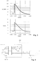
- Da der Brennkammerdruck als Folge des Ausströmens der Verbrennungsgase sinkt, müsste auch das Flächenverhältnis E sinken. Durch die Explosion eines stöchiometrischen Gemisches von Luft und Wasserstoff unter beispielsweise 20 bar Vordruck bei 300 °K wird eine maximale Verbrennungstemperatur von ca 2400 °C und ein Explosionsdruck von ca 150 bar erreicht. Beim Ausströmen sinkt der Druck im Explosionsraum bis zum Druckausgleich mit der Umgebung. Um jederzeit während des Ausströmens immer die maximale Gasgeschwindigkeit am Düsenende zu erreichen, sollte das ideale Flächenverhältnis ε deshalb idealerweise gemäss obiger Formel kontinuierlich von max. 15 auf ca 2 reduziert werden, dh das Düsenflächenverhältnis sollte idealerweise um den Faktor 7.5 variiert werden können.
-
Figur 3 zeigt einen entsprechenden Zeitverlauf eines Drucks pc in einer Explosionskammer und eines daraus resultierenden idealen Flächenverhältnisses ε = Ae/At. - Es soll also die Düse, beispielsweise eine konvergent-divergente Düse, gewährleisten, dass während der gesamten Ausströmzeit zumindest annähernd das optimale, ideale Flächenverhältnis zwischen Düsenende und Düsenhals eingestellt wird.
- Düsen üblicher Bauart, welche an Raketentriebwerken eingesetzt werden, haben eine fixe Geometrie. Da während des Betriebs die Leistung nicht verändert wird, ist es nicht notwendig, dass ihre Geometrie verstellt werden kann. Flugzeugtriebwerke mit Nachbrenner benötigen eine verstellbare Düse, da der engste Düsenquerschnitt bei Nachbrennerbetrieb vergrößert werden muss. Auch bei Gasturbinen sind verstellbare Düsen bekannt. Bei diesen Anwendungen werden die Düsen jeweils der Leistungsabgabe entsprechend verstellt aber dies immer relativ langsam, d.h. im Sekunden- bis Minutenbereich.
- Im Gegensatz dazu benötigt das Ausströmen aus dem Explosionsvolumen eines Impuls- oder Explosionsgenerators höchstens ein paar Millisekunden, d.h. die Düsengeometrie muss der Ausströmgeschwindigkeit und Explosionsfrequenz entsprechend sehr schnell verstellt werden können. Angestrebt werden hohe spezifische Leistungen des Generators und um dies zu erreichen sind hohe Explosionsfrequenzen notwendig, d.h. es werden Frequenzen von bis zu 50 Hz angestrebt.
- Der Schub F eines Triebwerks berechnet sich zu:

- ṁ = Massenstrom im Düsenhals
- we= Düsenaustrittsgeschwindigkeit
- pa= Umgebungsdruck
- Eine zu kurze Düse mit zu kleinem Flächenverhältnis ε vergibt Energie, da nicht die maximale Austrittsgeschwindigkeit erreicht wird. Eine zu lange Düse mit zu grossem Flächenverhältnis ε führt zu Überexpansion und der Schub wird durch den Gegendruck gebremst. Prinzipiell gibt es bei gegebenen Brennkammer- und Umgebungsdrücken jeweils genau ein optimales Flächenverhältnis E.
- In einer Ausführungsform wird diese Aufgabe gelöst durch eine ringförmige Düse mit einem rohrförmigen Aussenteil und einem konzentrischen, im wesentlichen kegelförmigen Innenteil, welche zueinander in axialer Richtung verstellbar sind. Ihre Kontur bildet jederzeit während des Ausströmens zumindest annähernd eine ideale Lavaldüse. Eine Aussengeometrie der Düse mit Hals- und Austrittsdurchmesser wird dabei vorzugsweise vorgängig festgelegt und für den maximal erreichbaren Schub ausgelegt. Der konzentrische Innenteil der Düse ist beweglich und verändert die Düsenhalsfläche oder Düseneintrittsfläche zumindest annähernd entsprechend dem idealen Flächenverhältnis.
- Es gibt verschiedene konvergent-divergente Düsenformen. Gebräuchlich sind beispielsweise eine konische Düse und eine Glockendüse.
- In einer Ausführungsform ist ein Regelventil zur Variation der Düseneintrittsfläche angeordnet, und ist die Stelleinrichtung ein Regelventilantrieb, welcher eine Bewegung des Regelventils zum Einstellen der Düseneintrittsfläche mindestens annähernd entsprechend dem genannten idealen Flächenverhältnis steuert.
- Es wird dabei also das gewünschte Flächenverhältnis durch Variation der Düseneintrittsfläche erreicht.
- Das Regelventil kann dabei mittels einer axialen Bewegung entlang einer Längsachse der Austrittsdüse bewegt werden. Die Austrittsdüse kann im wesentlichen rotationssymmetrisch geformt sein; eine Symmetrieachse dieser Rotationssymmetrie ist dabei gleich der Längsachse.
- In einer Ausführungsform weist das Regelventil eine Regelventilnadel auf, und ist die Düseneintrittsfläche durch die Position der Regelventilnadel bezüglich der Ablassöffnung bestimmt.
- In einer Ausführungsform weist die Regelventilnadel eine sich zu einer Ventilspitze hin verjüngende Aussenkontur auf, insbesondere eine zumindest annähernd kegelförmige Aussenkontur.
- In einer Ausführungsform bilden das Regelventil und ein Ventilsitz einen konvergent-divergenten Teil der Austrittsdüse.
- In einer Ausführungsform weist die Stelleinrichtung ein Antriebsmittel zum Antrieb einer Öffnungsbewegung des Regelventils auf, insbesondere indem das Antriebsmittel durch eine Hilfsexplosionsvorrichtung realisiert ist, in welcher eine Hilfsexplosion eine Kraft, welche die Öffnungsbewegung unterstützt, erzeugt.
- Details zum Antrieb mit einer solchen Hilfsexplosionsvorrichtung sind in der eingangs erwähnten
EP 2 319 036 A2 beschrieben. Insbesondere ist gemäss einer Ausführungsform möglich, die Explosion in der Hilfsexplosionsvorrichtung mit jener in der Explosionsraum mittels einer Leitung, auch Verzögerungsleitung genannt, zu synchronisieren. - Eine weitere Kraft oder Kraftkomponente, welche die Öffnungsbewegung unterstützt, kann durch den Rückstoss der ausströmenden Explosionsgase gegen das Regelventil entstehen.
- In einer Ausführungsform weist die Stelleinrichtung ein Bremsmittel zum Verzögern einer Öffnungsbewegung des Regelventils auf, insbesondere indem das Bremsmittel durch eine Gasdruckfeder oder durch eine Nockenwelle oder durch eine Gasdruckfeder in Kombination mit einer Nockenwelle realisiert ist.
- Antriebsmittel und Bremsmittel können auch durch eine einzige Vorrichtung realisiert sein, beispielsweise durch einen Kurbelantrieb.
- Beim Einsatz einer Nockenwelle oder eines Kurbelantriebs kann ein Schwungrad zum Ausgleich einer Drehbewegung der Nockenwelle respektive des Kurbelantriebs vorliegen.
- In einer Ausführungsform ist das Verschlusselement, dazu eingerichtet, die Ablassöffnung zeitweise gänzlich zu verschliessen. Damit ist es möglich, den Druck im Explosionsraum vor der Zündung über den Umgebungsdruck zu erhöhen.
- In einer Ausführungsform wirkt das Regelventil als Verschlusselement zum teilweisen oder gänzlichen Verschliessen der Ablassöffnung. Damit ist eine einfache Konstruktion mit wenigen bewegten Teilen möglich.
- In einer Ausführungsform liegt ein zusätzlich zum Regelventil wirkendes Schliessventil vor, welches als Verschlusselement zum teilweisen oder gänzlichen Verschliessen der Ablassöffnung wirkt. Damit kann das Regelventil vor Verschleiss geschützt werden.
- Ein Schliessventilantrieb zum Antreiben und/oder Abbremsen des Schliessventils kann in gleicher Weise wie eine der beschriebenen Ausführungsformen für den Regelventilantrieb gestaltet sein.
- Das Schliessventil kann dabei mittels einer axialen Bewegung entlang der Längsachse der Austrittsdüse bewegt werden.
- In einer Ausführungsform sind das Regelventil und das Schliessventil konzentrisch zueinander angeordnet.
- Das Schliessventil kann beispielsweise das Regelventil umschliessen und im Bereich der Ablassöffnung ein Ringventil bilden. Damit wird eine starke thermische und mechanische Beanspruchung durch das Schliessventil aufgenommen und nicht durch das Regelventil.
- In anderen Ausführungsformen wird das Flächenverhältnis durch Variation der Düsenaustrittsfläche erreicht. Dies kann durch Variation der Form respektive der Kontur der Düse über die Zeit geschehen, synchron mit den wiederholten Explosionen.
- In einer Ausführungsform geschieht dies durch Verschieben der Austrittsdüse oder eines Teiles der Austrittsdüse relativ zum Regelventil, insbesondere relativ zum sich verjüngenden Teil des Regelventils, also der Regelventilnadel. Es liegt dabei also vor: eine Vorrichtung gemäss mindestens einer der vorangehenden Ausführungsformen, wobei ein verstellbarer Düsenteil zur Variation der Düsenaustrittsfläche angeordnet ist, und eine Düsenverstelleinrichtung dazu eingerichtet ist, eine Bewegung des verstellbaren Düsenteils zum Einstellen der Düsenaustrittsfläche mindestens annähernd entsprechend dem genannten idealen Flächenverhältnis zu steuern. Insbesondere kann dabei der verstellbare Düsenteil in axialer Richtung relativ zum Regelventil verschoben werden.
- Die Düsenverstelleinrichtung kann dabei in gleicher Weise wie eine der hier beschriebenen Ausführungsformen von Regelventilantrieben oder Schliessventilantrieben realisiert werden.
- Falls auch die Düseneintrittsfläche variiert wird, ist die Änderung der Düseneintrittsfläche mit jener der Düsenaustrittsfläche koordiniert.
- Das Verfahren zum wiederholten Erzeugen von Explosionen weist die wiederholte Ausführung der folgenden Schritte auf, insbesondere in der angegebenen Reihenfolge:
- Zuführen eines fliessfähigen explosionsfähigen Materials in einen Explosionsraum, wobei eine Ablassöffnung des Explosionsraums mittels eines beweglichen Verschlusselements zumindest teilweise verschlossen ist, und Erzeugen eines Überdrucks im Explosionsraum bezüglich eines Umgebungsdrucks;
- Öffnen der Ablassöffnung;
- Zünden des explosionsfähigen Materials im Explosionsraum;
- Abführen von Explosionsgasen durch die Ablassöffnung und eine Austrittsdüse;
- Einstellen eines Flächenverhältnisses zwischen der Düseneintrittsfläche und der Düsenaustrittsfläche der Austrittsdüse, welches mindestens annähernd einem idealen Flächenverhältnis zur Erzeugung einer maximalen Austrittsgeschwindigkeit der Explosionsgase in Abhängigkeit des sinkenden Drucks im Explosionsraum folgt;
- zumindest teilweises Verschliessen der Ablassöffnung mittels des beweglichen Verschlusselements.
- In einer Ausführungsform findet der Schritt des Öffnens der Ablassöffnung vor dem Schritt des Zündens statt. Durch eine derart verzögerte Zündung wird eine thermische Beanspruchung des Ventilsitzes reduziert. Das Öffnen geschieht, je nach Ausführungsform, durch Öffnen des Regelventils oder des Schliessventils.
- Die Verzögerung zwischen dem Öffnen der Ablassöffnung (beispielsweise durch eine Hilfsexplosion zum Antrieb des entsprechenden Ventils) und der Zündung im Explosionsraum liegt typischerweise im Bereich von Bruchteilen von Millisekunden bis wenigen Millisekunden, beispielsweise zwischen 0.1 und 10 Millisekunden, z.B. zwischen 0.5 und 1 Millisekunde.
- In einer Ausführungsform geschieht das Zünden des explosionsfähigen Materials im Explosionsraum durch Leiten einer Explosion aus einer Hilfsexplosionvorrichtung durch eine Leitung zum Explosionsraum. Damit kann das folgende Problem vermieden werden: Bei Verwendung von Luft als Oxydator kann ein Übergang von einer Deflagration zur Detonation ("Deflagration-Detonation-Time", DDT) ziemlich lange dauern und ist abhängig von der Zündenergie. Bei einer direkten Zündung der Hauptexplosion mit einer Zündkerze könnte es dabei geschehen, dass in der Explosionskammer überhaupt keine Detonation mit starkem Druckanstieg erzeugt werden kann, oder dass die DDT zu lange dauert und ein Grossteil der Druckgase schon vor der Ausbildung der Hauptexplosion den Explosionsraum verlassen haben. Wird eine Hilfsexplosionvorrichtung mit beispielsweise einer Vorexplosionskammer verwendet, und die Explosion respektive Zündung mit einer Leitung (einem Rohr) der Zündung zum Explosionsraum übertragen, so ist die im Explosionsraum eingebrachte Energie um ein Vielfaches höher als bei der Zündkerze und es erfolgt zuverlässig eine Detonation. Die Hilfsexplosionsvorrichtung kann in der beschriebenen Weise nur zur Zündung im Explosionsraum eingesetzt werden, oder sie kann auch als Antrieb oder Teil des Antriebs des Regelventils oder des Schliessventils dienen.
- Weitere bevorzugte Ausführungsformen gehen aus den abhängigen Patentansprüchen hervor. Dabei sind Merkmale der Verfahrensansprüche sinngemäss mit den Vorrichtungsansprüchen kombinierbar und umgekehrt.
- Im folgenden wird der Erfindungsgegenstand anhand von bevorzugten Ausführungsbeispielen, welche in den beiliegenden Zeichnungen dargestellt sind, näher erläutert. Es zeigen jeweils schematisch:
- Figur 1
- eine Ausführungsform mit einem kombinierten Schliessventil und Regelventil;
- Figur 2
- eine Ausführungsform mit einem separaten Schliessventil und Regelventil;
- Figur 3
- Zeitverlauf eines Drucks in einer Explosionskammer und eines daraus resultierenden idealen Flächenverhältnisses; und
- Figur 4
- beispielhaft einen inneren Aufbau eines Regelventilantriebs oder Schliessventilantriebs.
- Grundsätzlich sind in den Figuren gleiche oder gleich wirkende Teile mit gleichen Bezugszeichen versehen.
-
Figur 1 zeigt eine Vorrichtung zum wiederholten Erzeugen von Explosionen: Ein Explosionsraum 11 ist über eine Zuführleitung 16 mit einem Füllventil 18 mit einem fliessfähigen explosionsfähigen Material befüllbar, beispielsweise einem explosiven Gasgemisch. Das Material kann mit einer Zündvorrichtung 19, beispielsweise einer Zündkerze, gezündet und zur Explosion gebracht werden. In einer anderen Ausführungsform wird das Material im Explosionsraum 11 über eine ebenfalls mit explosionsfähigem Material gefüllte Leitung oder Verzögerungsleitung 232 durch eine von einer Hilfsexplosionskammer einer Hilfsexplosionsvorrichtung 231 ausgehende und durch die Verzögerungsleitung 232 geführte Explosion gezündet. - Ein Austritt des Explosionsraums 11 führt durch eine Ablassöffnung 17 und eine Austrittsdüse 15. Die Austrittsdüse 15 ist eine Lavaldüse, mit einem konvergenten Düsenabschnitt 151, einem verstellbaren divergenten Düsenabschnitt 152 und einem fixen divergenten Düsenabschnitt 153. Die Verstellbarkeit des verstellbaren divergenten Düsenabschnitts 152 ist realisiert durch ein axial (also entlang einer Längsachse der Austrittsdüse 15) verstellbares Regelventil 21 mit einer Regelventilnadel 22. Die Regelventilnadel 22 ist im Bereich des verstellbaren divergenten Düsenabschnitts 152 angeordnet und ist sich verjüngend geformt, beispielsweise konisch. Dadurch nimmt die Düsenfläche im Bereich der Regelventilnadel 22 in Richtung der Düsenaustrittsfläche 14 hin zu, entsprechend der Abnahme eines Querschnittes der Regelventilnadel 22. In einem geschlossenen Zustand des Regelventils 21 verschliesst das Regelventil 21 an einem Ventilsitz 12 die Ablassöffnung 17 vollständig oder zumindest annähernd vollständig. Das Regelventil 21 kann somit auch als Schliessventil dienen.
- Bei einer Bewegung der Regelventilnadel 22 von der Düsenaustrittsfläche 14 weg nimmt an jedem Ort des verstellbaren divergenten Düsenabschnitts 152 und im Bereich der Ablassöffnung 17 der Querschnitt der Düse über die Zeit zu. Insbesondere nimmt eine Düsenhalsfläche oder Düseneintrittsfläche 13 im Bereich der Ablassöffnung 17 über die Zeit zu.
- Während des Füllens des Explosionsraums 11 mit einer explosionsfähigen Mischung aus Oxydator und Brennstoff dichtet das Regelventil 21 den Explosionsraum 11 gegen die Austrittsdüse 15 ab. Dadurch kann ein Überdruck erzeugt werden, mit dem wiederum ein hoher Explosionsdruck erzeugbar ist.
-
Figur 2 zeigt eine Ausführungsform mit einem separaten Schliessventil 31 und Regelventil 21. Die übrigen Elemente sind dieselben wie bei derFigur 1 . Diese Variante ist sinnvoll, wenn das Schliessventil 31 unabhängig vom Lavalventil oder Regelventil 21 sehr schnell bewegt werden soll. Dies ist insbesondere dann der Fall, wenn das Regelventil 21 mit Hilfe einer 231 Hilfsexplosionsvorrichtung angetrieben ist, beispielsweise wie inEP 2 319 036 A2 beschrieben. Das Schliessventil 31 kann separat vom Regelventil 21 bewegt werden. Ein Schliessventilantrieb 33 des Schliessventils 31 kann analog zu einem der möglichen Regelventilantriebe 23 ausgebildet sein. Die beiden Antriebe 23, 33 sind miteinander und mit einer Taktung der Explosionen im Explosionsraum 11 synchronisiert. - Das Schliessventil 31 verschliesst die Ablassöffnung 17 an einer Schliessventilringfläche 32.
- Es kann mit dem Schliessventil 31 sichergestellt werden, dass durch ein schnelles Öffnen vor der Zündung der Hauptexplosion nur wenig Gas durch die Austrittsdüse 15 entweicht. Damit wird eine Schwierigkeit gelöst, die bei einem kombinierten Schliess.- und Regelventil auftritt: bei einem solchen sollte gemäss einer Variante des Betriebsverfahrens das Ventil zunächst ganz und dicht geschlossen sein, dann sollte es sehr schnell öffnen, bis die optimale Düseneintrittsfläche 13 bei der Explosion vorliegt, und dann durch Vergrössern der Düseneintrittsfläche 13 relativ langsam dem idealen Flächenverhältnis folgen, und zuletzt wieder schnell schliessen.
- Durch die Trennung der Schliessfunktion von der Regelfunktion mittels des separaten Schliessventils 31 und die getrennnte Bewegbarkeit der beiden Ventile kann beispielsweise das Regelventil 21 bei der Zündung schon etwas geöffnet sein, und muss nicht vorher besonders schnell bewegt werden und auf die langsamere Bewegung zum Folgen des Flächenverhältnisses abgebremst werden. Das Schliessventil 31 wiederum kann sehr schnell geöffnet werden, insbesondere durch Antrieb mittels einer Hilfsexplosion.
- Der Antrieb des Regelventilantriebs 23 und oder des Schliessventilantriebs 33 kann durch irgendeine Kraft erfolgen, also beispielsweise pneumatisch, hydraulisch, durch einen Kurbelantrieb oder einen Nockenantrieb, oder mit einem (Hilfs-)Explosionsantrieb wie in
EP 2 319 036 A2 beschrieben. Es können auch mehrere Antriebsprinzipien miteinander kombiniert werden, wie beispielhaft inFigur 4 gezeigt: so kann ein (Hilfs-)Explosionsantrieb 231 mit einer Hilfs-Zündvorrichtung 235, beispielsweise einer Zündkerze, und einer Hilfsexplosionskammer 236 zum ersten Beschleunigen des Regelventils 21 bei der Öffnung eingesetzt werden (Mit der Verzögerungsleitung 232 wird die Explosion zum Explosionsraum 11 geführt). Dann kann ein Nockenantrieb oder eine Nockenwelle 234 oder ein Kurbelantrieb zum Bremsen und/oder zur Kontrolle der Geschwindigkeit des Regelventils 21 eingesetzt werden. Die Bewegung der Nockenwelle kann mit einem separaten Antrieb, beispielsweise elektrisch oder pneumatisch oder hydraulisch etc. gesteuert und/oder mit einem Schwungrad stabilisiert sein. Ferner kann eine Gasdruckfeder 233 zum Abbremsen der Bewegung des Regelventils 21 eingesetzt werden. Dabei können der Nockenantrieb 234 respektive der Kurbelantrieb mechanisch parallel (wie in der Figur gezeichnet) oder in Serie zur Gasdruckfeder 233 angeordnet sein. - Die Vorrichtung gemäss den
Figuren 1 oder 2 kann folgendermassen betrieben werden: - 1. Füllen des Explosionsraums 11 mit dem explosionsfähigen Material, beispielsweise einer Mischung aus einem Oxydator und einem Brennstoff. Das Regelventil 21 respektive das Schliessventil 31, falls vorhanden, ist in dieser Position geschlossen, eines oder mehrere Füllventile 18 sind geöffnet. Wird Luft als Oxydator verwendet, so kann diese aus dem Kompressor einer Gasturbine, einem Speicher oder einem sonstigen druckerzeugenden Aggregat stammen. Es ist auch denkbar, dass der Staudruck eines Flugzeugs die Luft verdichtet. Bei Verwendung von reinem Sauerstoff kann dieser aus einem Drucktank stammen.
- 2. Kurz vor Zündung der Explosion im Explosionsraum 11 werden das oder die Füllventile 18 geschlossen und kann das Regelventil 21 soweit geöffnet werden, dass das Flächenverhältnis ε zwischen Düsenende und Düsenhals einem idealen Flächenverhältnis beim Druck vor der Zündung entspricht.
- 3. Zündung des explosionsfähigen Materials. Das Schliessventil 31, falls vorhanden, wird geöffnet, ansonsten wird das Regelventil 21 geöffnet. Die hohe Explosionstemperatur kann es erforderlich machen, dass das entsprechende Ventil schon vor Zünden der Explosion etwas geöffnet ist. Das Ausströmen der Verbrennungsgase beginnt, und der Druck im Explosionsraum 11 sinkt. Nach dem Zünden wird durch einen Ventilweg, also durch Verschieben des Regelventils 21 in axialer Richtung bezüglich der Austrittsdüse 15, entsprechend einer Querschnittskontur respektive einer Kontur der Regelventilnadel 22 der Düsenhalsquerschnitt respektive die Düseneintrittsfläche 13 über die Zeit und mit dem abnehmenden Druck in der Explosionsraum 11 zumindest annähernd gemäss dem idealen Flächenverhältnis ε eingestellt. Die Verbrennungsgase werden im Düsenhals bis Schallgeschwindigkeit beschleunigt und anschliessend im divergenten Düsenteil weiter bis zur maximal erreichbaren Überschallgeschwindigkeit beschleunigt. Das Regelventil 21 wird kontinuierlich weiter geöffnet, bis die Düseneintrittsfläche 13 komplett frei gegeben ist und das minimale Flächenverhältnis ε erreicht ist und sich der Explosionsraum 11 weitgehend entleert hat.
- 4. Ist das Druck-Verhältnis von Umgebungsdruck und Brennkammerdruck im Gerät unter das kritische Druckverhältnis gesunken, wird das Regelventil 21 respektive das Schliessventil 31 geschlossen und die Vorrichtung ist bereit für den nächsten Takt.
Claims (12)
- Vorrichtung zum wiederholten Erzeugen von Explosionen, aufweisend einen Explosionsraum (11), eine Zufuhrleitung zum Zuführen eines fliessfähigen explosionsfähigen Materials, eine Ablassöffnung zum gerichteten Ablassen eines durch Zündung des explosionsfähigen Materials im Explosionsraum (11) erzeugten Gasdrucks, und ein bewegliches Verschlusselement (21, 31) zum teilweisen oder gänzlichen Verschliessen der Ablassöffnung (17), wobei die Vorrichtung eine Austrittsdüse (15) mit einer Düseneintrittsfläche (13) und einer Düsenaustrittsfläche (14) aufweist,sowie eine Stelleinrichtung (23), welche dazu ausgebildet ist, nach einem Öffnen der Ablassöffnung (17) und einem Ausströmen von Explosionsgasen durch die Austrittsdüse (15) ein Flächenverhältnis zwischen der Düseneintrittsfläche (13) und der Düsenaustrittsfläche (14) einzustellen, welches mindestens annähernd einem idealen Flächenverhältnis zur Erzeugung einer maximalen Austrittsgeschwindigkeit der Explosionsgase in Abhängigkeit des Drucks im Explosionsraum (11) folgt,dadurch gekennzeichnet, dass ein Regelventil (21) zur Variation der Düseneintrittsfläche (13) angeordnet ist, und die Stelleinrichtung (23) ein Regelventilantrieb ist, welcher eine Bewegung des Regelventils (21) zum Einstellen der Düseneintrittsfläche (13) entsprechend dem genannten idealen Flächenverhältnis steuert,wobei das Regelventil (21) eine Regelventilnadel (22) aufweist, und die Düseneintrittsfläche (13) durch die Position der Regelventilnadel (22) bezüglich der Ablassöffnung (17) bestimmt ist.
- Vorrichtung gemäss Anspruch 1, wobei die Regelventilnadel (22) eine sich zu einer Ventilspitze hin verjüngende Aussenkontur aufweist, insbesondere eine zumindest annähernd kegelförmige Aussenkontur.
- Vorrichtung gemäss Anspruch 1 oder 2, wobei das Regelventil (21) und ein Ventilsitz (12) einen konvergent-divergenten Teil der Austrittsdüse (15) bilden.
- Vorrichtung gemäss einem der Ansprüche 1 bis 3, wobei die Stelleinrichtung (23) ein Antriebsmittel zum Antrieb einer Öffnungsbewegung des Regelventils (21) aufweist, insbesondere indem das Antriebsmittel durch eine Hilfsexplosionsvorrichtung (231) realisiert ist, in welcher eine Hilfsexplosion eine Kraft, welche die Öffnungsbewegung unterstützt, erzeugt.
- Vorrichtung gemäss einem der Ansprüche 1 bis 4, wobei die Stelleinrichtung (23) ein Bremsmittel zum Verzögern einer Öffnungsbewegung des Regelventils (21) aufweist, insbesondere indem das Bremsmittel durch eine Gasdruckfeder (232) oder durch eine Nockenwelle (233) oder durch eine Gasdruckfeder (232) in Kombination mit einer Nockenwelle (233) realisiert ist.
- Vorrichtung gemäss einem der vorangehenden Ansprüche, in welcher das Verschlusselement (21, 31) dazu eingerichtet ist, die Ablassöffnung (17) zeitweise gänzlich zu verschliessen.
- Vorrichtung gemäss einem der Ansprüche 1 bis 6, in welcher das Regelventil (21) als Verschlusselement zum teilweisen oder gänzlichen Verschliessen der Ablassöffnung (17) wirkt.
- Vorrichtung gemäss einem der Ansprüche 1 bis 6, aufweisend ein zusätzlich zum Regelventil (21) wirkendes Schliessventil (31), welches als Verschlusselement zum teilweisen oder gänzlichen Verschliessen der Ablassöffnung (17) wirkt.
- Vorrichtung gemäss Anspruch 8, wobei das Regelventil (21) und das Schliessventil (31) konzentrisch zueinander angeordnet sind.
- Verfahren zum wiederholten Erzeugen von Explosionen, mit der wiederholten Ausführung der folgenden Schritte:• Zuführen eines fliessfähigen explosionsfähigen Materials in einen Explosionsraum (11), wobei eine Ablassöffnung (17) des Explosionsraums (11) mittels eines beweglichen Verschlusselements (21, 31) zumindest teilweise verschlossen ist, und Erzeugen eines Überdrucks im Explosionsraum (11) bezüglich eines Umgebungsdrucks;• Öffnen der Ablassöffnung (17);• Zünden des explosionsfähigen Materials im Explosionsraum (11);• Abführen von Explosionsgasen durch die Ablassöffnung (17) und eine Austrittsdüse (15);• Einstellen eines Flächenverhältnisses zwischen der Düseneintrittsfläche (13) und der Düsenaustrittsfläche (14) der Austrittsdüse (15), welches mindestens annähernd einem idealen Flächenverhältnis zur Erzeugung einer maximalen Austrittsgeschwindigkeit der Explosionsgase in Abhängigkeit des sinkenden Drucks im Explosionsraum (11) folgt; und• zumindest teilweises Verschliessen der Ablassöffnung (17) mittels des beweglichen Verschlusselements (21, 31);dadurch gekennzeichnet, dass der Schritt des Einstellens des Flächenverhältnisses mittels eines Regelventils (21) erfolgt, welches eine Düseneintrittsfläche (13) der Austrittsdüse (15) variiert,
wobei ein Regelventilantrieb eine Bewegung des Regelventils (21) zum Einstellen der Düseneintrittsfläche (13) entsprechend dem genannten idealen Flächenverhältnis steuert,
wobei das Regelventil (21) eine Regelventilnadel (22) aufweist, und die Düseneintrittsfläche (13) durch die Position der Regelventilnadel (22) bezüglich der Ablassöffnung (17) bestimmt ist. - Verfahren gemäss Anspruch 10, wobei der Schritt des Öffnens der Ablassöffnung (17) vor dem Schritt des Zündens stattfindet.
- Verfahren gemäss Anspruch 10 oder 11, wobei das Zünden des explosionsfähigen Materials im Explosionsraum (11) durch Leiten einer Explosion aus einer Hilfsexplosionsvorrichtung (235) durch eine Leitung (232) zum Explosionsraum (11) geschieht.
Applications Claiming Priority (2)
| Application Number | Priority Date | Filing Date | Title |
|---|---|---|---|
| CH00776/14A CH709681A1 (de) | 2014-05-21 | 2014-05-21 | Pulsdetonationsantrieb. |
| PCT/CH2015/000077 WO2015176190A1 (de) | 2014-05-21 | 2015-05-18 | Pulsdetonationsantrieb |
Publications (3)
| Publication Number | Publication Date |
|---|---|
| EP3146270A1 EP3146270A1 (de) | 2017-03-29 |
| EP3146270B1 true EP3146270B1 (de) | 2021-09-01 |
| EP3146270B8 EP3146270B8 (de) | 2021-11-24 |
Family
ID=51224636
Family Applications (1)
| Application Number | Title | Priority Date | Filing Date |
|---|---|---|---|
| EP15724927.7A Active EP3146270B8 (de) | 2014-05-21 | 2015-05-18 | Vorrichtung und verfahren zum wiederholten erzeugen von explosionen zum antrieb eines luftfahrzeuges |
Country Status (4)
| Country | Link |
|---|---|
| US (1) | US10359004B2 (de) |
| EP (1) | EP3146270B8 (de) |
| CH (1) | CH709681A1 (de) |
| WO (1) | WO2015176190A1 (de) |
Families Citing this family (4)
| Publication number | Priority date | Publication date | Assignee | Title |
|---|---|---|---|---|
| US10174718B2 (en) * | 2016-09-10 | 2019-01-08 | James Peter Strasser | Combustion operated impulse drive unit |
| CN107013943A (zh) * | 2017-03-10 | 2017-08-04 | 中国人民解放军装备学院 | 采用射流对撞燃烧方式的在线可调式燃气发生器 |
| CH714304A1 (de) * | 2017-11-06 | 2019-05-15 | Explotechnik AG | Pulsantrieb. |
| CN111927650B (zh) * | 2020-07-13 | 2022-08-16 | 西安航天动力研究所 | 液体火箭发动机高频燃烧不稳定试验用反压雾化仓结构 |
Citations (1)
| Publication number | Priority date | Publication date | Assignee | Title |
|---|---|---|---|---|
| US20080098711A1 (en) * | 2006-10-27 | 2008-05-01 | Cfd Research Corporation | Constant Volume Rocket Motor |
Family Cites Families (14)
| Publication number | Priority date | Publication date | Assignee | Title |
|---|---|---|---|---|
| US2390161A (en) * | 1941-11-07 | 1945-12-04 | Mercier Pierre Ernest | Airplane power plant |
| US2515644A (en) * | 1947-03-11 | 1950-07-18 | Daniel And Florence Guggenheim | Rotating valve for multiple resonance combustion chambers |
| US4726184A (en) * | 1985-09-09 | 1988-02-23 | Rockwell International Corporation | Rocket engine assembly |
| US5345758A (en) * | 1993-04-14 | 1994-09-13 | Adroit Systems, Inc. | Rotary valve multiple combustor pulse detonation engine |
| US5394690A (en) * | 1993-09-20 | 1995-03-07 | The United States Of America As Represented By The Secretary Of The Army | Constant pressure, variable thrust bipropellant engine |
| FR2734025B1 (fr) * | 1995-05-11 | 1997-08-01 | Europ Propulsion | Moteur fusee a propergol liquide, a impulsions |
| US5941062A (en) * | 1995-05-11 | 1999-08-24 | Societe Europeenne De Propulsion | Pulse rocket engine |
| CA2438661C (en) | 2001-02-15 | 2011-05-31 | University Of Chicago | Yeast screens for agents affecting protein folding |
| US7849695B1 (en) * | 2001-09-17 | 2010-12-14 | Alliant Techsystems Inc. | Rocket thruster comprising load-balanced pintle valve |
| US6981365B1 (en) | 2001-12-28 | 2006-01-03 | Sierra Engineering Incorporated | Supersonic revolving nozzle |
| US6964154B1 (en) * | 2003-03-11 | 2005-11-15 | The United States Of America As Represented By The Administrator Of The National Aeronautics And Space Administration | Axisymmetric, throttleable non-gimballed rocket engine |
| FR2855556B1 (fr) * | 2003-05-28 | 2007-04-13 | Mbda France | Moteur a detonations pulsees |
| CH699486A2 (de) | 2008-09-04 | 2010-03-15 | Explo Engineering Gmbh | Vorrichtung und verfahren zum erzeugen von explosionen. |
| US20130298523A1 (en) * | 2009-02-12 | 2013-11-14 | Joseph D. Sims | Constant pressure aerospike thruster |
-
2014
- 2014-05-21 CH CH00776/14A patent/CH709681A1/de not_active Application Discontinuation
-
2015
- 2015-05-18 WO PCT/CH2015/000077 patent/WO2015176190A1/de not_active Ceased
- 2015-05-18 EP EP15724927.7A patent/EP3146270B8/de active Active
- 2015-05-18 US US15/311,870 patent/US10359004B2/en not_active Expired - Fee Related
Patent Citations (1)
| Publication number | Priority date | Publication date | Assignee | Title |
|---|---|---|---|---|
| US20080098711A1 (en) * | 2006-10-27 | 2008-05-01 | Cfd Research Corporation | Constant Volume Rocket Motor |
Also Published As
| Publication number | Publication date |
|---|---|
| US10359004B2 (en) | 2019-07-23 |
| EP3146270B8 (de) | 2021-11-24 |
| EP3146270A1 (de) | 2017-03-29 |
| US20170082069A1 (en) | 2017-03-23 |
| CH709681A1 (de) | 2015-11-30 |
| WO2015176190A1 (de) | 2015-11-26 |
Similar Documents
| Publication | Publication Date | Title |
|---|---|---|
| DE970090C (de) | Rueckstossduese fuer Rueckstosstriebwerke | |
| EP3098426B1 (de) | Adaptives flugzeugtriebwerk | |
| EP3776529B1 (de) | Vorrichtung zur erzeugung von druckwellen hoher amplitude | |
| DE602004000988T2 (de) | Pulsiertes Detonationssystem für Gasturbinen | |
| EP3146270A1 (de) | Pulsdetonationsantrieb | |
| DE1526817A1 (de) | Konvergente-divergente Strahltriebswerksaustrittsduese | |
| EP3707364B1 (de) | Pulsantrieb | |
| DE10259567A1 (de) | Brennkraftbetriebenes Setzgerät | |
| EP1922568B1 (de) | Verfahren und vorrichtung zum erzeugen von druckwellen | |
| DE1069952C2 (de) | Vorrichtung zur Schubregelung von Heißstrahltriebwerken | |
| CH250563A (de) | Rückstossantrieb für Fahrzeuge, insbesondere Flugzeuge. | |
| DE1079897B (de) | Staustrahltriebwerk | |
| EP3475553B1 (de) | Zündgerät sowie zündverfahren | |
| DE102007023966B4 (de) | Leichtgaskanone und Verfahren zum Beschleunigen eines festen Gegenstandes mittels einer solchen Leichtgaskanone | |
| DE768042C (de) | Heissstrahltriebwerk mit doppelter Kraftstoffeinspritzung zum Vortrieb von Luftfahrzeugen | |
| DE1014794B (de) | Intermittierend arbeitender Gaserzeuger, insbesondere fuer Triebwerke | |
| DE232234C (de) | ||
| DE10302041B4 (de) | Injektor-Zentrifugen-Turbinen-Triebwerk und Injektor-Zentrifugen-Luftstrahl-Triebwerk | |
| DE949700C (de) | Rueckstroemdrossel | |
| DE945967C (de) | Zweikreis-Turbinenstrahltriebwerk | |
| DE138707C (de) | ||
| DE102007057275A1 (de) | Pulsationstriebwerk mit innenliegender Treibstoff-Einspritzung | |
| DE1007118B (de) | Gasturbinenanlage | |
| AT137237B (de) | Erzeuger von gespannten Verbrennungsgasen. | |
| CH283880A (de) | Strahltriebwerk mit intermittierender Verbrennung. |
Legal Events
| Date | Code | Title | Description |
|---|---|---|---|
| STAA | Information on the status of an ep patent application or granted ep patent |
Free format text: STATUS: THE INTERNATIONAL PUBLICATION HAS BEEN MADE |
|
| PUAI | Public reference made under article 153(3) epc to a published international application that has entered the european phase |
Free format text: ORIGINAL CODE: 0009012 |
|
| STAA | Information on the status of an ep patent application or granted ep patent |
Free format text: STATUS: REQUEST FOR EXAMINATION WAS MADE |
|
| 17P | Request for examination filed |
Effective date: 20161121 |
|
| AK | Designated contracting states |
Kind code of ref document: A1 Designated state(s): AL AT BE BG CH CY CZ DE DK EE ES FI FR GB GR HR HU IE IS IT LI LT LU LV MC MK MT NL NO PL PT RO RS SE SI SK SM TR |
|
| AX | Request for extension of the european patent |
Extension state: BA ME |
|
| DAV | Request for validation of the european patent (deleted) | ||
| DAX | Request for extension of the european patent (deleted) | ||
| STAA | Information on the status of an ep patent application or granted ep patent |
Free format text: STATUS: EXAMINATION IS IN PROGRESS |
|
| 17Q | First examination report despatched |
Effective date: 20200415 |
|
| GRAP | Despatch of communication of intention to grant a patent |
Free format text: ORIGINAL CODE: EPIDOSNIGR1 |
|
| STAA | Information on the status of an ep patent application or granted ep patent |
Free format text: STATUS: GRANT OF PATENT IS INTENDED |
|
| INTG | Intention to grant announced |
Effective date: 20200929 |
|
| GRAJ | Information related to disapproval of communication of intention to grant by the applicant or resumption of examination proceedings by the epo deleted |
Free format text: ORIGINAL CODE: EPIDOSDIGR1 |
|
| STAA | Information on the status of an ep patent application or granted ep patent |
Free format text: STATUS: EXAMINATION IS IN PROGRESS |
|
| INTC | Intention to grant announced (deleted) | ||
| GRAP | Despatch of communication of intention to grant a patent |
Free format text: ORIGINAL CODE: EPIDOSNIGR1 |
|
| STAA | Information on the status of an ep patent application or granted ep patent |
Free format text: STATUS: GRANT OF PATENT IS INTENDED |
|
| INTG | Intention to grant announced |
Effective date: 20210330 |
|
| GRAS | Grant fee paid |
Free format text: ORIGINAL CODE: EPIDOSNIGR3 |
|
| GRAA | (expected) grant |
Free format text: ORIGINAL CODE: 0009210 |
|
| STAA | Information on the status of an ep patent application or granted ep patent |
Free format text: STATUS: THE PATENT HAS BEEN GRANTED |
|
| AK | Designated contracting states |
Kind code of ref document: B1 Designated state(s): AL AT BE BG CH CY CZ DE DK EE ES FI FR GB GR HR HU IE IS IT LI LT LU LV MC MK MT NL NO PL PT RO RS SE SI SK SM TR |
|
| REG | Reference to a national code |
Ref country code: GB Ref legal event code: FG4D Free format text: NOT ENGLISH |
|
| REG | Reference to a national code |
Ref country code: CH Ref legal event code: EP Ref country code: AT Ref legal event code: REF Ref document number: 1426616 Country of ref document: AT Kind code of ref document: T Effective date: 20210915 |
|
| REG | Reference to a national code |
Ref country code: DE Ref legal event code: R096 Ref document number: 502015015137 Country of ref document: DE |
|
| REG | Reference to a national code |
Ref country code: IE Ref legal event code: FG4D Free format text: LANGUAGE OF EP DOCUMENT: GERMAN |
|
| REG | Reference to a national code |
Ref country code: CH Ref legal event code: PK Free format text: BERICHTIGUNG B8 |
|
| RAP4 | Party data changed (patent owner data changed or rights of a patent transferred) |
Owner name: EXPLOTECHNIK AG |
|
| REG | Reference to a national code |
Ref country code: DE Ref legal event code: R081 Ref document number: 502015015137 Country of ref document: DE Owner name: P-WAVE AG, CH Free format text: FORMER OWNER: EXPLOTECHNIK AG, WALTENSCHWIEL, CH Ref country code: DE Ref legal event code: R081 Ref document number: 502015015137 Country of ref document: DE Owner name: P-WAVE AG, CH Free format text: FORMER OWNER: EXPLO ENGINEERING AG, WALTENSCHWIL, CH Ref country code: DE Ref legal event code: R081 Ref document number: 502015015137 Country of ref document: DE Owner name: EXPLOTECHNIK AG, CH Free format text: FORMER OWNER: EXPLOTECHNIK AG, WALTENSCHWIEL, CH Ref country code: DE Ref legal event code: R081 Ref document number: 502015015137 Country of ref document: DE Owner name: EXPLOTECHNIK AG, CH Free format text: FORMER OWNER: EXPLO ENGINEERING AG, WALTENSCHWIL, CH |
|
| REG | Reference to a national code |
Ref country code: LT Ref legal event code: MG9D |
|
| REG | Reference to a national code |
Ref country code: NL Ref legal event code: MP Effective date: 20210901 |
|
| PG25 | Lapsed in a contracting state [announced via postgrant information from national office to epo] |
Ref country code: NO Free format text: LAPSE BECAUSE OF FAILURE TO SUBMIT A TRANSLATION OF THE DESCRIPTION OR TO PAY THE FEE WITHIN THE PRESCRIBED TIME-LIMIT Effective date: 20211201 Ref country code: ES Free format text: LAPSE BECAUSE OF FAILURE TO SUBMIT A TRANSLATION OF THE DESCRIPTION OR TO PAY THE FEE WITHIN THE PRESCRIBED TIME-LIMIT Effective date: 20210901 Ref country code: FI Free format text: LAPSE BECAUSE OF FAILURE TO SUBMIT A TRANSLATION OF THE DESCRIPTION OR TO PAY THE FEE WITHIN THE PRESCRIBED TIME-LIMIT Effective date: 20210901 Ref country code: BG Free format text: LAPSE BECAUSE OF FAILURE TO SUBMIT A TRANSLATION OF THE DESCRIPTION OR TO PAY THE FEE WITHIN THE PRESCRIBED TIME-LIMIT Effective date: 20211201 Ref country code: LT Free format text: LAPSE BECAUSE OF FAILURE TO SUBMIT A TRANSLATION OF THE DESCRIPTION OR TO PAY THE FEE WITHIN THE PRESCRIBED TIME-LIMIT Effective date: 20210901 Ref country code: RS Free format text: LAPSE BECAUSE OF FAILURE TO SUBMIT A TRANSLATION OF THE DESCRIPTION OR TO PAY THE FEE WITHIN THE PRESCRIBED TIME-LIMIT Effective date: 20210901 Ref country code: SE Free format text: LAPSE BECAUSE OF FAILURE TO SUBMIT A TRANSLATION OF THE DESCRIPTION OR TO PAY THE FEE WITHIN THE PRESCRIBED TIME-LIMIT Effective date: 20210901 Ref country code: HR Free format text: LAPSE BECAUSE OF FAILURE TO SUBMIT A TRANSLATION OF THE DESCRIPTION OR TO PAY THE FEE WITHIN THE PRESCRIBED TIME-LIMIT Effective date: 20210901 |
|
| PG25 | Lapsed in a contracting state [announced via postgrant information from national office to epo] |
Ref country code: PL Free format text: LAPSE BECAUSE OF FAILURE TO SUBMIT A TRANSLATION OF THE DESCRIPTION OR TO PAY THE FEE WITHIN THE PRESCRIBED TIME-LIMIT Effective date: 20210901 Ref country code: LV Free format text: LAPSE BECAUSE OF FAILURE TO SUBMIT A TRANSLATION OF THE DESCRIPTION OR TO PAY THE FEE WITHIN THE PRESCRIBED TIME-LIMIT Effective date: 20210901 Ref country code: GR Free format text: LAPSE BECAUSE OF FAILURE TO SUBMIT A TRANSLATION OF THE DESCRIPTION OR TO PAY THE FEE WITHIN THE PRESCRIBED TIME-LIMIT Effective date: 20211202 |
|
| PG25 | Lapsed in a contracting state [announced via postgrant information from national office to epo] |
Ref country code: IS Free format text: LAPSE BECAUSE OF FAILURE TO SUBMIT A TRANSLATION OF THE DESCRIPTION OR TO PAY THE FEE WITHIN THE PRESCRIBED TIME-LIMIT Effective date: 20220101 Ref country code: SM Free format text: LAPSE BECAUSE OF FAILURE TO SUBMIT A TRANSLATION OF THE DESCRIPTION OR TO PAY THE FEE WITHIN THE PRESCRIBED TIME-LIMIT Effective date: 20210901 Ref country code: SK Free format text: LAPSE BECAUSE OF FAILURE TO SUBMIT A TRANSLATION OF THE DESCRIPTION OR TO PAY THE FEE WITHIN THE PRESCRIBED TIME-LIMIT Effective date: 20210901 Ref country code: RO Free format text: LAPSE BECAUSE OF FAILURE TO SUBMIT A TRANSLATION OF THE DESCRIPTION OR TO PAY THE FEE WITHIN THE PRESCRIBED TIME-LIMIT Effective date: 20210901 Ref country code: PT Free format text: LAPSE BECAUSE OF FAILURE TO SUBMIT A TRANSLATION OF THE DESCRIPTION OR TO PAY THE FEE WITHIN THE PRESCRIBED TIME-LIMIT Effective date: 20220103 Ref country code: NL Free format text: LAPSE BECAUSE OF FAILURE TO SUBMIT A TRANSLATION OF THE DESCRIPTION OR TO PAY THE FEE WITHIN THE PRESCRIBED TIME-LIMIT Effective date: 20210901 Ref country code: EE Free format text: LAPSE BECAUSE OF FAILURE TO SUBMIT A TRANSLATION OF THE DESCRIPTION OR TO PAY THE FEE WITHIN THE PRESCRIBED TIME-LIMIT Effective date: 20210901 Ref country code: CZ Free format text: LAPSE BECAUSE OF FAILURE TO SUBMIT A TRANSLATION OF THE DESCRIPTION OR TO PAY THE FEE WITHIN THE PRESCRIBED TIME-LIMIT Effective date: 20210901 Ref country code: AL Free format text: LAPSE BECAUSE OF FAILURE TO SUBMIT A TRANSLATION OF THE DESCRIPTION OR TO PAY THE FEE WITHIN THE PRESCRIBED TIME-LIMIT Effective date: 20210901 |
|
| REG | Reference to a national code |
Ref country code: DE Ref legal event code: R097 Ref document number: 502015015137 Country of ref document: DE |
|
| PLBE | No opposition filed within time limit |
Free format text: ORIGINAL CODE: 0009261 |
|
| STAA | Information on the status of an ep patent application or granted ep patent |
Free format text: STATUS: NO OPPOSITION FILED WITHIN TIME LIMIT |
|
| PG25 | Lapsed in a contracting state [announced via postgrant information from national office to epo] |
Ref country code: IT Free format text: LAPSE BECAUSE OF FAILURE TO SUBMIT A TRANSLATION OF THE DESCRIPTION OR TO PAY THE FEE WITHIN THE PRESCRIBED TIME-LIMIT Effective date: 20210901 Ref country code: DK Free format text: LAPSE BECAUSE OF FAILURE TO SUBMIT A TRANSLATION OF THE DESCRIPTION OR TO PAY THE FEE WITHIN THE PRESCRIBED TIME-LIMIT Effective date: 20210901 |
|
| 26N | No opposition filed |
Effective date: 20220602 |
|
| PG25 | Lapsed in a contracting state [announced via postgrant information from national office to epo] |
Ref country code: SI Free format text: LAPSE BECAUSE OF FAILURE TO SUBMIT A TRANSLATION OF THE DESCRIPTION OR TO PAY THE FEE WITHIN THE PRESCRIBED TIME-LIMIT Effective date: 20210901 |
|
| REG | Reference to a national code |
Ref country code: CH Ref legal event code: PL |
|
| REG | Reference to a national code |
Ref country code: DE Ref legal event code: R081 Ref document number: 502015015137 Country of ref document: DE Owner name: P-WAVE AG, CH Free format text: FORMER OWNER: EXPLOTECHNIK AG, WALTENSCHWIL, CH |
|
| REG | Reference to a national code |
Ref country code: BE Ref legal event code: MM Effective date: 20220531 |
|
| PG25 | Lapsed in a contracting state [announced via postgrant information from national office to epo] |
Ref country code: MC Free format text: LAPSE BECAUSE OF FAILURE TO SUBMIT A TRANSLATION OF THE DESCRIPTION OR TO PAY THE FEE WITHIN THE PRESCRIBED TIME-LIMIT Effective date: 20210901 Ref country code: LU Free format text: LAPSE BECAUSE OF NON-PAYMENT OF DUE FEES Effective date: 20220518 Ref country code: LI Free format text: LAPSE BECAUSE OF NON-PAYMENT OF DUE FEES Effective date: 20220531 Ref country code: CH Free format text: LAPSE BECAUSE OF NON-PAYMENT OF DUE FEES Effective date: 20220531 |
|
| PG25 | Lapsed in a contracting state [announced via postgrant information from national office to epo] |
Ref country code: IE Free format text: LAPSE BECAUSE OF NON-PAYMENT OF DUE FEES Effective date: 20220518 |
|
| PG25 | Lapsed in a contracting state [announced via postgrant information from national office to epo] |
Ref country code: BE Free format text: LAPSE BECAUSE OF NON-PAYMENT OF DUE FEES Effective date: 20220531 |
|
| P01 | Opt-out of the competence of the unified patent court (upc) registered |
Effective date: 20230321 |
|
| REG | Reference to a national code |
Ref country code: AT Ref legal event code: MM01 Ref document number: 1426616 Country of ref document: AT Kind code of ref document: T Effective date: 20220518 |
|
| PG25 | Lapsed in a contracting state [announced via postgrant information from national office to epo] |
Ref country code: AT Free format text: LAPSE BECAUSE OF NON-PAYMENT OF DUE FEES Effective date: 20220518 |
|
| PG25 | Lapsed in a contracting state [announced via postgrant information from national office to epo] |
Ref country code: HU Free format text: LAPSE BECAUSE OF FAILURE TO SUBMIT A TRANSLATION OF THE DESCRIPTION OR TO PAY THE FEE WITHIN THE PRESCRIBED TIME-LIMIT; INVALID AB INITIO Effective date: 20150518 |
|
| PG25 | Lapsed in a contracting state [announced via postgrant information from national office to epo] |
Ref country code: MK Free format text: LAPSE BECAUSE OF FAILURE TO SUBMIT A TRANSLATION OF THE DESCRIPTION OR TO PAY THE FEE WITHIN THE PRESCRIBED TIME-LIMIT Effective date: 20210901 Ref country code: CY Free format text: LAPSE BECAUSE OF FAILURE TO SUBMIT A TRANSLATION OF THE DESCRIPTION OR TO PAY THE FEE WITHIN THE PRESCRIBED TIME-LIMIT Effective date: 20210901 |
|
| PG25 | Lapsed in a contracting state [announced via postgrant information from national office to epo] |
Ref country code: MT Free format text: LAPSE BECAUSE OF FAILURE TO SUBMIT A TRANSLATION OF THE DESCRIPTION OR TO PAY THE FEE WITHIN THE PRESCRIBED TIME-LIMIT Effective date: 20210901 |
|
| PGFP | Annual fee paid to national office [announced via postgrant information from national office to epo] |
Ref country code: DE Payment date: 20250521 Year of fee payment: 11 |
|
| PGFP | Annual fee paid to national office [announced via postgrant information from national office to epo] |
Ref country code: GB Payment date: 20250521 Year of fee payment: 11 |
|
| PGFP | Annual fee paid to national office [announced via postgrant information from national office to epo] |
Ref country code: FR Payment date: 20250528 Year of fee payment: 11 |
|
| PG25 | Lapsed in a contracting state [announced via postgrant information from national office to epo] |
Ref country code: TR Free format text: LAPSE BECAUSE OF FAILURE TO SUBMIT A TRANSLATION OF THE DESCRIPTION OR TO PAY THE FEE WITHIN THE PRESCRIBED TIME-LIMIT Effective date: 20210901 |