EP3146134B1 - Élément de renforcement vertical réglable pour vantail de fenêtre ou porte pouvant être déplacée d'un plan vers un plan parallèle - Google Patents
Élément de renforcement vertical réglable pour vantail de fenêtre ou porte pouvant être déplacée d'un plan vers un plan parallèle Download PDFInfo
- Publication number
- EP3146134B1 EP3146134B1 EP15719215.4A EP15719215A EP3146134B1 EP 3146134 B1 EP3146134 B1 EP 3146134B1 EP 15719215 A EP15719215 A EP 15719215A EP 3146134 B1 EP3146134 B1 EP 3146134B1
- Authority
- EP
- European Patent Office
- Prior art keywords
- vertical reinforcement
- longitudinal axis
- displacement means
- vertical
- reinforcement according
- Prior art date
- Legal status (The legal status is an assumption and is not a legal conclusion. Google has not performed a legal analysis and makes no representation as to the accuracy of the status listed.)
- Active
Links
- 230000002787 reinforcement Effects 0.000 title claims description 20
- 229910000831 Steel Inorganic materials 0.000 claims description 4
- 239000010959 steel Substances 0.000 claims description 4
- 238000006073 displacement reaction Methods 0.000 claims 14
- 241000638935 Senecio crassissimus Species 0.000 claims 1
- 239000003351 stiffener Substances 0.000 description 18
- 230000007935 neutral effect Effects 0.000 description 5
- 230000015572 biosynthetic process Effects 0.000 description 2
- 238000011161 development Methods 0.000 description 2
- 230000018109 developmental process Effects 0.000 description 2
- 238000004519 manufacturing process Methods 0.000 description 2
- 230000003014 reinforcing effect Effects 0.000 description 2
- HCHKCACWOHOZIP-UHFFFAOYSA-N Zinc Chemical compound [Zn] HCHKCACWOHOZIP-UHFFFAOYSA-N 0.000 description 1
- 238000005452 bending Methods 0.000 description 1
- 230000001419 dependent effect Effects 0.000 description 1
- 230000008030 elimination Effects 0.000 description 1
- 238000003379 elimination reaction Methods 0.000 description 1
- 238000003780 insertion Methods 0.000 description 1
- 230000037431 insertion Effects 0.000 description 1
- 239000007787 solid Substances 0.000 description 1
- 239000011701 zinc Substances 0.000 description 1
- 229910052725 zinc Inorganic materials 0.000 description 1
Images
Classifications
-
- E—FIXED CONSTRUCTIONS
- E05—LOCKS; KEYS; WINDOW OR DOOR FITTINGS; SAFES
- E05D—HINGES OR SUSPENSION DEVICES FOR DOORS, WINDOWS OR WINGS
- E05D15/00—Suspension arrangements for wings
- E05D15/06—Suspension arrangements for wings for wings sliding horizontally more or less in their own plane
- E05D15/10—Suspension arrangements for wings for wings sliding horizontally more or less in their own plane movable out of one plane into a second parallel plane
- E05D15/1005—Suspension arrangements for wings for wings sliding horizontally more or less in their own plane movable out of one plane into a second parallel plane the wing being supported on arms movable in horizontal planes
- E05D15/1013—Suspension arrangements for wings for wings sliding horizontally more or less in their own plane movable out of one plane into a second parallel plane the wing being supported on arms movable in horizontal planes specially adapted for windows
-
- E—FIXED CONSTRUCTIONS
- E05—LOCKS; KEYS; WINDOW OR DOOR FITTINGS; SAFES
- E05Y—INDEXING SCHEME ASSOCIATED WITH SUBCLASSES E05D AND E05F, RELATING TO CONSTRUCTION ELEMENTS, ELECTRIC CONTROL, POWER SUPPLY, POWER SIGNAL OR TRANSMISSION, USER INTERFACES, MOUNTING OR COUPLING, DETAILS, ACCESSORIES, AUXILIARY OPERATIONS NOT OTHERWISE PROVIDED FOR, APPLICATION THEREOF
- E05Y2201/00—Constructional elements; Accessories therefor
- E05Y2201/60—Suspension or transmission members; Accessories therefor
- E05Y2201/622—Suspension or transmission members elements
- E05Y2201/638—Cams; Ramps
-
- E—FIXED CONSTRUCTIONS
- E05—LOCKS; KEYS; WINDOW OR DOOR FITTINGS; SAFES
- E05Y—INDEXING SCHEME ASSOCIATED WITH SUBCLASSES E05D AND E05F, RELATING TO CONSTRUCTION ELEMENTS, ELECTRIC CONTROL, POWER SUPPLY, POWER SIGNAL OR TRANSMISSION, USER INTERFACES, MOUNTING OR COUPLING, DETAILS, ACCESSORIES, AUXILIARY OPERATIONS NOT OTHERWISE PROVIDED FOR, APPLICATION THEREOF
- E05Y2600/00—Mounting or coupling arrangements for elements provided for in this subclass
- E05Y2600/10—Adjustable
- E05Y2600/20—Adjustable with specific transmission movement
-
- E—FIXED CONSTRUCTIONS
- E05—LOCKS; KEYS; WINDOW OR DOOR FITTINGS; SAFES
- E05Y—INDEXING SCHEME ASSOCIATED WITH SUBCLASSES E05D AND E05F, RELATING TO CONSTRUCTION ELEMENTS, ELECTRIC CONTROL, POWER SUPPLY, POWER SIGNAL OR TRANSMISSION, USER INTERFACES, MOUNTING OR COUPLING, DETAILS, ACCESSORIES, AUXILIARY OPERATIONS NOT OTHERWISE PROVIDED FOR, APPLICATION THEREOF
- E05Y2600/00—Mounting or coupling arrangements for elements provided for in this subclass
- E05Y2600/10—Adjustable
- E05Y2600/30—Adjustment motion
- E05Y2600/31—Linear motion
- E05Y2600/312—Horizontal motion
-
- E—FIXED CONSTRUCTIONS
- E05—LOCKS; KEYS; WINDOW OR DOOR FITTINGS; SAFES
- E05Y—INDEXING SCHEME ASSOCIATED WITH SUBCLASSES E05D AND E05F, RELATING TO CONSTRUCTION ELEMENTS, ELECTRIC CONTROL, POWER SUPPLY, POWER SIGNAL OR TRANSMISSION, USER INTERFACES, MOUNTING OR COUPLING, DETAILS, ACCESSORIES, AUXILIARY OPERATIONS NOT OTHERWISE PROVIDED FOR, APPLICATION THEREOF
- E05Y2600/00—Mounting or coupling arrangements for elements provided for in this subclass
- E05Y2600/60—Mounting or coupling members; Accessories therefor
- E05Y2600/62—Bolts
-
- E—FIXED CONSTRUCTIONS
- E05—LOCKS; KEYS; WINDOW OR DOOR FITTINGS; SAFES
- E05Y—INDEXING SCHEME ASSOCIATED WITH SUBCLASSES E05D AND E05F, RELATING TO CONSTRUCTION ELEMENTS, ELECTRIC CONTROL, POWER SUPPLY, POWER SIGNAL OR TRANSMISSION, USER INTERFACES, MOUNTING OR COUPLING, DETAILS, ACCESSORIES, AUXILIARY OPERATIONS NOT OTHERWISE PROVIDED FOR, APPLICATION THEREOF
- E05Y2800/00—Details, accessories and auxiliary operations not otherwise provided for
- E05Y2800/15—Applicability
- E05Y2800/17—Universally applicable
- E05Y2800/176—Universally applicable on different wing types, weights or sizes
-
- E—FIXED CONSTRUCTIONS
- E05—LOCKS; KEYS; WINDOW OR DOOR FITTINGS; SAFES
- E05Y—INDEXING SCHEME ASSOCIATED WITH SUBCLASSES E05D AND E05F, RELATING TO CONSTRUCTION ELEMENTS, ELECTRIC CONTROL, POWER SUPPLY, POWER SIGNAL OR TRANSMISSION, USER INTERFACES, MOUNTING OR COUPLING, DETAILS, ACCESSORIES, AUXILIARY OPERATIONS NOT OTHERWISE PROVIDED FOR, APPLICATION THEREOF
- E05Y2800/00—Details, accessories and auxiliary operations not otherwise provided for
- E05Y2800/67—Materials; Strength alteration thereof
- E05Y2800/682—Strength alteration by reinforcing, e.g. by applying ribs
-
- E—FIXED CONSTRUCTIONS
- E05—LOCKS; KEYS; WINDOW OR DOOR FITTINGS; SAFES
- E05Y—INDEXING SCHEME ASSOCIATED WITH SUBCLASSES E05D AND E05F, RELATING TO CONSTRUCTION ELEMENTS, ELECTRIC CONTROL, POWER SUPPLY, POWER SIGNAL OR TRANSMISSION, USER INTERFACES, MOUNTING OR COUPLING, DETAILS, ACCESSORIES, AUXILIARY OPERATIONS NOT OTHERWISE PROVIDED FOR, APPLICATION THEREOF
- E05Y2900/00—Application of doors, windows, wings or fittings thereof
- E05Y2900/10—Application of doors, windows, wings or fittings thereof for buildings or parts thereof
- E05Y2900/13—Type of wing
- E05Y2900/148—Windows
Definitions
- the invention relates to an adjustable vertical stiffening for a movable wing of a window, a door or the like, wherein the vertical stiffening has a trained in the form of a bolt Abstellstoff whose first end is directly or indirectly mounted on a horizontal spar of the wing and the second end, the is opposite to the first end in the direction of the longitudinal axis of the Abstellstoffs, is coupled to a mounting member of the vertical stiffener, wherein the mounting member is mounted on a vertical spar of the wing.
- the fitting part has a projection.
- the projection acts in the form of a "deformation die", which generates a bias in the assembly of the fitting part to the wing, which compensates for a distortion of the wing due to the wing weight.
- the DE 87 09 299 U1 discloses a vertical stiffener for a support member of a deployable wing, wherein the vertical stiffener has a plate which can be screwed onto the wing.
- the DE 88 04 738 U1 discloses a fitting for a parkable via Ausstellarme door leaf.
- the door has a support member which is attached to a lower wing spar.
- the support member is stiffened by an elongated reinforcing member which is loosely arranged in the sash.
- the reinforcing member can be rigidly bolted to the support member.
- a bolted to a sliding wing vertical stiffening is further from the EP 0 443 176 A1 known.
- WO 2012/095806 A1 which describes the features of the preamble of claim 1, discloses a further development of DE 101 10 722 A1 ,
- a vertical stiffening for sliding sash which has a mounting element and a parking means.
- the mounting element is mounted on a vertical wing spar and the parking means is indirectly connected to a horizontal wing spar.
- Abstellstoff and mounting element are connected to each other via a screw whose longitudinal direction is aligned perpendicular to the wing main plane. By means of an actuation of the screw, the distance between the parking means and the mounting element can be adjusted. By changing this distance, the angle between the vertical wing spar and the horizontal wing spar changed.
- Warp compensation can be adjusted by the screw, depending on the amount of twist between the horizontal wing spar and the vertical wing spar. In other words, can be adjusted by the screw, how much of the bending away under the load of the wing horizontal wing spar again "pulled” on the vertical wing spar “pulled” or “pushed away” this.
- the known vertical stiffening is adjustable by a "screwing” or “unscrewing” the screw in the Abstellstoff or the vertical wing spar.
- the strength of the connection between Abstellstoff and mounting element or vertical wing spar varies due to the differently far screwed screw.
- the strength of the connection between Abstellstoff and mounting member or vertical wing spar depends on how far a user has screwed the screw to compensate for the distortion of the wing spars. This is from a comparison of FIGS. 2 to 4 as well as from a comparison of FIGS. 5a and 5b the WO 2012/095806 A1 seen.
- the invention is the object of the invention to provide an adjustable vertical stiffening for a shieldable wing of a window, a door or the like, in which the strength of the vertical stiffening is independent of the setting of the vertical stiffening.
- an adjustable vertical stiffening for a movable wing of a window, a door or the like, wherein the vertical stiffening has a trained in the form of a bolt Abstellstoff whose first end is directly or indirectly mounted on a horizontal spar of the wing and its second end, which is opposite to the first end in the direction of the longitudinal axis of the Abstellstoffs coupled to a mounting member of the vertical stiffener, wherein the mounting member is mounted on a vertical spar of the wing and wherein the vertical stiffening at least partially rotatably mounted on the mounting member arranged rotary member with a slotted guide has, which extends at least partially radially to the longitudinal axis of the rotary member and in the direction of the longitudinal axis of the rotary member rises, wherein the second end of the Abstellstoffs engages within the slotted guide in this.
- the at least partially radially extending to the longitudinal axis and increasing in the direction of the longitudinal axis slotted guide is in other words formed externally threaded portion.
- the slotted guide extends substantially between 160 ° and 200 ° radially to the longitudinal axis of the rotary member.
- the slotted guide is preferably formed only in sections on an outer side of the rotary member.
- the slotted guide extends substantially through 180 ° radially to the longitudinal axis of the rotary member. In this case, the user can turn the rotary element by ⁇ 90 ° for torsion compensation.
- the longitudinal axis of the Abstellstoffs extends parallel to the longitudinal axis of the mounting member, when the second end of the Abstellstoffs engages centrally in the longitudinal direction of the slotted guide in the slide guide.
- the vertical stiffening in this case is formed so that the longitudinal axes of the mounting member and the Abstellstoffs are parallel when the Abstellstoff centered in the slotted guide, wherein the center of the slotted guide "halfway" between the ends of the slotted guide is located.
- a user is thereby by means of rotation of the rotary element in a position to both "take” the Abstellstoff to the mounting element and the Abstellstoff "push away” of the mounting element.
- the slide guide is at least partially formed step-shaped.
- the set by a user position of the rotary member can be kept safe even under heavy load of the vertical stiffening.
- the step-shaped design of the slotted guide allows a discrete and thus better reproducible adjustment of the vertical stiffening.
- the vertical stiffening invention also allows the compensation of a strong twist when the slide guide has a stroke in the direction of the longitudinal axis of the rotary member of 4 mm to 6 mm, in particular of 5 mm.
- a stable, yet structurally simple and inexpensively manufacturable vertical stiffening can be achieved when the rotary member is rotatably riveted to the mounting element.
- a particularly convenient for the user setting the vertical stiffening is made possible when the rotary member has a mark for indicating the rotational position of the rotary member.
- the Marking can be arranged or formed on an end face of the rotary member.
- the marking is particularly preferably arranged or formed on the rotary element such that the marking in plan view of the rotary element is aligned with the parking means when the longitudinal axis of the parking means extends parallel to the longitudinal axis of the mounting element. The user can thus easily read at the mark that the vertical stiffening is in a "neutral position".
- the marking is in the form of a notch.
- the rotating element may have a tool engagement.
- the tool engagement is formed on an end face of the rotary member.
- the tool engagement is particularly preferably in the form of an inner polygon, for example, a hexagon socket (Allen) or a driving profile formed in multi-round shape (Torx).
- the costs for producing the vertical stiffening can be greatly reduced if the rotary element is designed as a cast part, in particular made of zinc.
- the production of the rotary element is further simplified if it is substantially cylindrical, wherein the slotted guide runs at least in sections on the lateral surface of the cylinder.
- the parking means is designed in the form of a steel bolt.
- the parking means preferably has in the region of its second end extending in the direction of the longitudinal axis of the parking means Longitudinal flattening in order to "draw” both the Abstellstoff close to the mounting element and to allow a compact formation of the vertical stiffening.
- the vertical stiffening is furthermore designed to be particularly compact if the mounting element is substantially plate-shaped, in particular in the form of a sheet, preferably in the form of a steel sheet.
- the vertical stiffening is structurally particularly simple in design, when the guide passage recess is formed in the form of a guide passage tab on the mounting member.
- the mounting element may have a first guide web which engages in a transverse to the direction of the longitudinal axis of the Abstellstoffs extending first transverse recess to hold the Abstellstoff rotationally fixed to the mounting member.
- the mounting element has a second guide web, which engages in a transverse to the direction of the longitudinal axis of the Abstellstoffs extending second transverse recess to hold the Abstellstoff rotationally fixed to the mounting member. A tilting of the Vertical stiffening upon actuation of the rotary member can be safely avoided.
- the vertical stiffening is structurally particularly simple and therefore inexpensive to manufacture, if the guide passage tab, the first guide bar and / or the second guide bar are integrally formed with the mounting member.
- the invention further relates to a window, a door or the like with a previously described vertical stiffening.
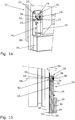
- FIG. 1a shows a first adjustable vertical stiffener 10 which is mounted on a removable wing 12 of a door.
- the first vertical reinforcement 10 has a parking means 14, a mounting element 16 and a rotary element 18.
- the mounting member 16 is by four screws mounted a vertical spar 20 of the wing 12. For reasons of clarity, the screws provided for this purpose, which are insertable into screw holes 22, 24, 26, 27 of the mounting element 16, are not shown.
- the parking means 14 is connected via a first end 28 with a horizontal rail 30 of the wing 12. Since the first end 28 in FIG. 1a is covered by the horizontal spar 30, the reference numeral 28 is shown in dashed lines.
- a second end 32 opposite the first end 28 engages a slotted guide 34 of the rotary member 18.
- FIG. 1b shows a sectional side view of the arrangement FIG. 1a with the first vertical stiffener 10.
- the parking means 14 is formed in the form of a bolt.
- the first end 28 of the parking means 14 is inserted into a recess 36, here in the form of a through-hole, of the horizontal spar 30.
- the second end 32 of the parking means 14 is arranged in the slotted guide 34.
- the rotary member 18 is formed substantially cylindrical. Its lateral surface has in sections the slotted guide 34.
- a first end face 38 of the rotary member 18 has a tool engagement 40 for insertion of a socket portion. At one of the first end face 38 opposite end face 42 of the rotary member 18, this has a substantially cylindrical projection 44.
- the projection 44 is rotatably disposed in a through-hole 46 of the mounting member 16.
- the projection 44 is riveted to the mounting member 16 in the region of the through-hole 46 in order to achieve a fixed connection of the rotary member 18 to the mounting member 16 in the direction of the longitudinal axis 48 of the rotary member 18.
- the first vertical stiffener 10 is in FIG. 1b shown in the neutral position.
- the parking means 14 can be pivoted in the direction of a double arrow 54 relative to the mounting member 16 to compensate for a distortion of the horizontal beam 30 relative to the vertical spar 20. This is especially true of the following FIGS. 2a to 4b clear.
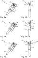
- FIG. 2a shows the first vertical stiffener 10 in a perspective view in the neutral position.
- the slide guide 34 extends substantially at 180 ° radially to the longitudinal axis 48 of the rotary member 18th
- FIG. 2b shows the first vertical stiffener 10 according to FIG. 2a in the side view, being off FIG. 2b it can be seen that the slide guide 34 is formed on a lateral surface 56 of the rotary member 18.
- FIG. 3a shows the first vertical stiffener 10 in a first end position. This can be seen for a user by a mark 58 on the first end face 38 of the rotary member 18. In the neutral position of the first vertical stiffener 10, the marking 58 is aligned with the Abstellstoff 14 (see FIG. 2a ).
- FIG. 3b shows a side view of the first vertical stiffening 10 according to FIG. 3a , Out FIG. 3b It can be seen that the parking means 14 has a longitudinal flat 59 in order to pivot the parking means 14 close to the mounting member 16 can. Out FIG. 3b Furthermore, it can be seen that the slotted guide 34 increases continuously and linearly in the direction of the longitudinal axis 48 of the rotary element 18. The Rotation of the rotary element 18 thus causes a linear pivoting of the parking means 14th
- FIG. 4a shows the first vertical stiffener 10 in a second end position. In this second end position, the parking means 14 is pivoted away from the mounting element 16 at a maximum.
- FIG. 4b shows the first vertical stiffener 10 in this second end position in a side view. From a comparison of FIGS. 3b and 4b It can be seen that the slotted guide 34 in the direction of the longitudinal axis 48 of the rotary member 18 has a stroke H.
- the stroke H in the present example, the first vertical stiffening 10 is about 5 mm.
- the second end 32 of the parking means 14 can be moved by rotation of the rotary member 18 by approximately ⁇ 2.5 mm relative to the mounting member 16.
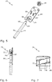
- FIG. 5 shows an itemized perspective view of the first vertical stiffening 10.
- the mounting member 16 is formed substantially plate-shaped.
- the mounting member 16 has a ceremoniess trimgangsausANSung 60, which represents a hinge point by which the Abstellstoff 14 is tilted by rotation of the rotary member 18.
- the ceremoniess trimgangsausANS 60 allows a particularly compact and solid design of the first vertical stiffening 10.
- the ceremoniess trimgangsausANSANS 60 is formed in a guide passage tab 61 on the mounting member 16.
- the mounting element 16 also has a first guide web 62, which engages in a transverse to the longitudinal axis 50 of the Abstellstoffs 14 extending first transverse recess 64.
- first guide web 62 engages in a transverse to the longitudinal axis 50 of the Abstellstoffs 14 extending first transverse recess 64.
- a second guide web 66 of the mounting element 16 engages in a second transverse recess 68, which extends transversely to the longitudinal axis 50 of the parking means 14.
- the guide passage tab 61 and the guide webs 62, 66 are formed integrally or integrally with the mounting member 16.
- FIG. 6 shows a second vertical stiffener 70, which is identical to the previously described first vertical stiffener 10. However, a slotted guide 72 of a rotary member 74 is step-shaped.
- FIG. 7 shows the rotary member 74 according to FIG. 6 in an enlarged view.
- the slide guide 72 has a plurality of steps 76, 78, 80, so that a second end 82 (see FIG. 6 ) of a parking means 84 is gradually pivoted by rotating the rotary member 74.
- a provision of the second vertical stiffening after adjustment by the user is reliably avoided.
- the invention relates to a vertical stiffening for a door or window sash.
- the vertical stiffener allows for twist compensation of a vertical stile relative to a horizontal spar of the door or window sash.
- the vertical stiffener has a bolt-shaped parking means, which is formed at one end for engagement in the horizontal rail and the other end engages in a rotary element of the vertical stiffening.
- the rotary member is rotatable about its longitudinal axis, but fixed in its direction of its longitudinal axis on a, in particular plate-shaped, mounting member arranged, which is attachable to the vertical spar.
- the rotary member has a slotted guide, in which engages one end of the Abstellstoffs.
- the slotted guide can be designed in steps.
- the rotary member preferably has a tool engagement on the front side for its actuation. A rotation of the rotary element causes a pivoting of the Abstellstoffs relative to the mounting element, whereby a twisting of the door or window sash is compensate
Landscapes
- Engineering & Computer Science (AREA)
- Mechanical Engineering (AREA)
- Power-Operated Mechanisms For Wings (AREA)
- Pivots And Pivotal Connections (AREA)
- Body Structure For Vehicles (AREA)
- Hinges (AREA)
- Wing Frames And Configurations (AREA)
- Door And Window Frames Mounted To Openings (AREA)
Claims (15)
- Élément de renforcement vertical réglable (10, 70) pour un vantail écartable (12) d'une fenêtre ou d'une porte, l'élément de renforcement vertical (10, 70) présentant un moyen d'écartement (14, 84) sous la forme d'un axe pour effectuer une compensation de torsion entre le montant horizontal et le montant vertical du vantail, dont la première extrémité (28) peut être montée indirectement ou directement sur un montant horizontal (30) du vantail (12) et dont la deuxième extrémité (32, 82), qui est opposée à la première extrémité (28) dans la direction de l'axe longitudinal (50) du moyen d'écartement (14, 84), est reliée à un élément de montage (16) de l'élément de renforcement vertical (10, 70), l'élément de montage (16) pouvant être monté sur un montant vertical (20) du vantail (12), l'élément de renforcement vertical réglable (10, 70) présentant un élément rotatif (18, 74) qui est disposé au moins partiellement rotatif sur l'élément de montage (16),
caractérisé en ce que l'élément rotatif (18, 74) présente un guide de coulisse (34, 72) qui s'étend au moins sur certaines parties radialement par rapport à l'axe longitudinal (48) de l'élément rotatif (18, 74) et s'élève dans une direction de l'axe longitudinal (48) de l'élément rotatif (18, 74), la deuxième extrémité (32, 82) du moyen d'écartement (14, 84) s'engageant, à l'intérieur du guide de coulisse (34, 72), dans celui-ci. - Élément de renforcement vertical selon la revendication 1, dans lequel le guide de coulisse (34, 72) s'étend sensiblement entre 160° et 200°, en particulier sensiblement sur 180°, radialement par rapport à l'axe longitudinal (48) de l'élément rotatif (18, 74).
- Élément de renforcement vertical selon la revendication 2, dans lequel l'axe longitudinal (50) du moyen d'écartement (14, 84) s'étend parallèlement à l'axe longitudinal (52) de l'élément de montage (16) lorsque la deuxième extrémité (32, 82) du moyen d'écartement (14, 84) s'engage au centre dans le guide de coulisse (34, 72) dans la direction longitudinale du guide de coulisse (34, 72).
- Élément de renforcement vertical selon l'une des revendications précédentes, dans lequel le guide de coulisse (72) est formé de manière étagée au moins sur certaines parties.
- Élément de renforcement vertical selon l'une des revendications précédentes, dans lequel le guide de coulisse (34, 72) présente une course (H) de 4 mm à 6 mm, en particulier de 5 mm, dans la direction de l'axe longitudinal (48) de l'élément rotatif (18, 74).
- Élément de renforcement vertical selon l'une des revendications précédentes, dans lequel l'élément rotatif (18, 74) est riveté rotatif sur l'élément de montage (16).
- Élément de renforcement vertical selon l'une des revendications précédentes, dans lequel le moyen d'écartement (14, 84) est réalisé sous la forme d'un axe en acier.
- Élément de renforcement vertical selon l'une des revendications précédentes, dans lequel le moyen d'écartement (14, 84) présente, dans la zone de sa deuxième extrémité (34, 82), un aplatissement longitudinal (59) qui s'étend dans la direction de l'axe longitudinal (50) du moyen d'écartement (14).
- Élément de renforcement vertical selon l'une des revendications précédentes, dans lequel l'élément de montage (16) est réalisé sensiblement en forme de plaque, en particulier sous la forme d'une tôle, de préférence sous la forme d'une tôle en acier.
- Élément de renforcement vertical selon l'une des revendications précédentes, dans lequel l'élément de montage (16) présente un évidement de passage de guidage (60) à travers lequel le moyen d'écartement (14, 84) est guidé, l'évidement de passage de guidage (60) représentant un point d'articulation autour duquel le moyen d'écartement (14, 84) peut être basculé par une rotation de l'élément rotatif (18, 74).
- Élément de renforcement vertical selon la revendication 10, dans lequel l'évidement de passage de guidage (60) est formé dans une patte de passage de guidage (61) sur l'élément de montage (16).
- Élément de renforcement vertical selon l'une des revendications précédentes, dans lequel l'élément de montage (16) présente une première barrette de guidage (62) qui s'engage dans un premier évidement transversal (64) s'étendant transversalement à la direction de l'axe longitudinal (50) du moyen d'écartement (14, 84) pour maintenir le moyen d'écartement (14, 84) fixe en rotation sur l'élément de montage (16).
- Élément de renforcement vertical selon la revendication 12, dans lequel l'élément de montage (16) présente une deuxième barrette de guidage (66) qui s'engage dans un deuxième évidement transversal (68) s'étendant transversalement à la direction de l'axe longitudinal (50) du moyen d'écartement (14, 84) pour maintenir le moyen d'écartement (14, 84) fixe en rotation sur l'élément de montage (14, 84).
- Élément de renforcement vertical selon la revendication 13 en liaison avec la revendication 11, dans lequel la patte de passage de guidage (61), la première barrette de guidage (62) et/ou la deuxième barrette de guidage (66) sont formées d'une seule pièce avec l'élément de montage (16).
- Fenêtre ou porte munie d'un élément de renforcement vertical (10, 70) selon l'une des revendications précédentes.
Priority Applications (1)
| Application Number | Priority Date | Filing Date | Title |
|---|---|---|---|
| PL15719215T PL3146134T3 (pl) | 2014-05-23 | 2015-04-28 | Nastawne usztywnienie pionowe z jarzmem dla odstawnego skrzydła okna albo drzwi |
Applications Claiming Priority (2)
| Application Number | Priority Date | Filing Date | Title |
|---|---|---|---|
| DE102014209915.3A DE102014209915B3 (de) | 2014-05-23 | 2014-05-23 | Einstellbare Vertikalaussteifung mit Kulisse für einen abstellbaren Flügel eines Fensters oder einer Tür |
| PCT/EP2015/059168 WO2015176924A1 (fr) | 2014-05-23 | 2015-04-28 | Élément de renforcement vertical réglable comprenant une coulisse pour un vantail déplaçable d'une fenêtre ou d'une porte |
Publications (2)
| Publication Number | Publication Date |
|---|---|
| EP3146134A1 EP3146134A1 (fr) | 2017-03-29 |
| EP3146134B1 true EP3146134B1 (fr) | 2019-04-10 |
Family
ID=53015807
Family Applications (1)
| Application Number | Title | Priority Date | Filing Date |
|---|---|---|---|
| EP15719215.4A Active EP3146134B1 (fr) | 2014-05-23 | 2015-04-28 | Élément de renforcement vertical réglable pour vantail de fenêtre ou porte pouvant être déplacée d'un plan vers un plan parallèle |
Country Status (8)
| Country | Link |
|---|---|
| EP (1) | EP3146134B1 (fr) |
| CN (1) | CN106460429B (fr) |
| DE (1) | DE102014209915B3 (fr) |
| ES (1) | ES2730022T3 (fr) |
| PL (1) | PL3146134T3 (fr) |
| RU (1) | RU2671764C2 (fr) |
| TR (1) | TR201909248T4 (fr) |
| WO (1) | WO2015176924A1 (fr) |
Family Cites Families (11)
| Publication number | Priority date | Publication date | Assignee | Title |
|---|---|---|---|---|
| DE8709299U1 (fr) * | 1987-07-06 | 1987-08-27 | W. Hautau Gmbh, 3068 Helpsen, De | |
| DE8804738U1 (fr) * | 1988-04-11 | 1988-05-26 | W. Hautau Gmbh, 3068 Helpsen, De | |
| DE9001921U1 (fr) * | 1990-02-19 | 1990-04-19 | Gretsch-Unitas Gmbh Baubeschlaege, 7257 Ditzingen, De | |
| DE29907975U1 (de) * | 1999-04-30 | 1999-08-05 | Gretsch Unitas Gmbh | Laufschuh für einen Parallelschiebe- und Kippbeschlag eines Gebäudefensters oder einer Gebäudefenstertür sowie Gebäudefenster bzw. Gebäudefenstertür mit einem solchen Parallelschiebe-Kippbeschlag |
| DE10110722B4 (de) * | 2000-03-11 | 2015-09-24 | Hautau Gmbh | Beschlag für einen Schiebeflügel |
| ATE397140T1 (de) * | 2002-06-28 | 2008-06-15 | Hautau Gmbh | Verwindungskompensation von abstellbaren flügeln |
| DE202005012310U1 (de) * | 2005-07-22 | 2006-11-23 | Hettich-Oni Gmbh & Co. Kg | Dämpfungseinrichtung |
| RU59683U1 (ru) * | 2006-07-17 | 2006-12-27 | Закрытое акционерное общество "Прок" | Профильные системы для изготовления оконных и дверных конструкций |
| DE102008004355B4 (de) * | 2008-01-15 | 2015-03-12 | Roto Frank Ag | Einstellbares Ecklager für einen Flügel eines Fensters, einer Tür oder dergleichen |
| EP2663710B1 (fr) * | 2011-01-14 | 2014-12-17 | Hautau GmbH | Élément de renforcement vertical réglable pour un vantail coulissant |
| EP2698492B1 (fr) * | 2012-08-16 | 2018-10-10 | Roto Frank AG | Palier d'angle réglable pour un battant de fenêtre, de porte ou analogue |
-
2014
- 2014-05-23 DE DE102014209915.3A patent/DE102014209915B3/de not_active Expired - Fee Related
-
2015
- 2015-04-28 CN CN201580027320.9A patent/CN106460429B/zh active Active
- 2015-04-28 EP EP15719215.4A patent/EP3146134B1/fr active Active
- 2015-04-28 RU RU2016149659A patent/RU2671764C2/ru active
- 2015-04-28 TR TR2019/09248T patent/TR201909248T4/tr unknown
- 2015-04-28 WO PCT/EP2015/059168 patent/WO2015176924A1/fr active Application Filing
- 2015-04-28 PL PL15719215T patent/PL3146134T3/pl unknown
- 2015-04-28 ES ES15719215T patent/ES2730022T3/es active Active
Non-Patent Citations (1)
| Title |
|---|
| None * |
Also Published As
| Publication number | Publication date |
|---|---|
| RU2016149659A3 (fr) | 2018-09-10 |
| CN106460429A (zh) | 2017-02-22 |
| WO2015176924A1 (fr) | 2015-11-26 |
| DE102014209915B3 (de) | 2015-07-02 |
| RU2671764C2 (ru) | 2018-11-06 |
| CN106460429B (zh) | 2018-03-16 |
| TR201909248T4 (tr) | 2019-07-22 |
| EP3146134A1 (fr) | 2017-03-29 |
| ES2730022T3 (es) | 2019-11-07 |
| PL3146134T3 (pl) | 2019-07-31 |
| RU2016149659A (ru) | 2018-06-25 |
Similar Documents
| Publication | Publication Date | Title |
|---|---|---|
| EP2873792B1 (fr) | Penture | |
| EP3103948B1 (fr) | Penture pour une porte ou une fenêtre | |
| EP3613931B1 (fr) | Module de bande destiné au raccordement mobile par charnière autour d'un axe de charnière d'un battant sur un cadre | |
| EP2158372B1 (fr) | Charnière de porte ou de fenêtre | |
| EP3175068B1 (fr) | Système de ferrure | |
| WO2012095806A1 (fr) | Élément de renforcement vertical réglable pour un vantail coulissant | |
| EP2345786B1 (fr) | Penture de porte pour portes en aluminium | |
| EP3146134B1 (fr) | Élément de renforcement vertical réglable pour vantail de fenêtre ou porte pouvant être déplacée d'un plan vers un plan parallèle | |
| EP2696018B1 (fr) | Compas pivotant, dispositif de logement et système de guidage pour fenêtre basculante parallèle | |
| EP2345787B1 (fr) | Penture de porte pour portes en aluminium | |
| WO2010121588A2 (fr) | Bâti et armoire de commande montée sur ledit bâti | |
| DE202015100200U1 (de) | Bandlappenanordnung eines Bandes | |
| DE102014012029A1 (de) | Laufwagenanordnung für schwer heb- und bewegbare Flügel eines Fensters oder einer Tür | |
| EP2740872B1 (fr) | Palier d'angle prévu pour l'agencement recouvert | |
| EP3028884B1 (fr) | Unité de support | |
| WO2020001841A1 (fr) | Ensemble d'une bande pour une liaison articulée avec charnière autour d'un axe de charnière d'un battant sur un cadre ainsi que bande pourvue de cet ensemble | |
| DE2712957A1 (de) | Verstellbares lager fuer ein insbesondere dreh- und kippbares fenster, eine tuer o.dgl. | |
| EP3428374A1 (fr) | Dispositif articulé à résistance au pivotement dépendante de la direction | |
| DE102013226720B4 (de) | Einstellbare Vertikalaussteifung mit Gleiter für einen abstellbaren Flügel eines Fensters einer Tür oder dergleichen | |
| DE102013226716B4 (de) | Einstellbare Vertikalaussteifung mit Exzenter für einen abstellbaren Flügel eines Fensters, einer Tür oder dergleichen | |
| EP3348773A1 (fr) | Dispositif d'ouverture, de fermeture et de verrouillage des lamelles d'une structure en lamelles | |
| EP2674558B1 (fr) | Agencement d'actionnement de porte | |
| EP2045426B1 (fr) | Dispositif de fixation d'un pivot pour battant de fenêtre | |
| EP3543444B1 (fr) | Palier pour un dispositif de ferrure d'une fenêtre | |
| EP3279417A1 (fr) | Unite d'ailes d'une ferrure et procede de montage d'une telle unite d'ailes |
Legal Events
| Date | Code | Title | Description |
|---|---|---|---|
| STAA | Information on the status of an ep patent application or granted ep patent |
Free format text: STATUS: THE INTERNATIONAL PUBLICATION HAS BEEN MADE |
|
| PUAI | Public reference made under article 153(3) epc to a published international application that has entered the european phase |
Free format text: ORIGINAL CODE: 0009012 |
|
| STAA | Information on the status of an ep patent application or granted ep patent |
Free format text: STATUS: REQUEST FOR EXAMINATION WAS MADE |
|
| 17P | Request for examination filed |
Effective date: 20161019 |
|
| AK | Designated contracting states |
Kind code of ref document: A1 Designated state(s): AL AT BE BG CH CY CZ DE DK EE ES FI FR GB GR HR HU IE IS IT LI LT LU LV MC MK MT NL NO PL PT RO RS SE SI SK SM TR |
|
| AX | Request for extension of the european patent |
Extension state: BA ME |
|
| DAV | Request for validation of the european patent (deleted) | ||
| DAX | Request for extension of the european patent (deleted) | ||
| STAA | Information on the status of an ep patent application or granted ep patent |
Free format text: STATUS: EXAMINATION IS IN PROGRESS |
|
| 17Q | First examination report despatched |
Effective date: 20180323 |
|
| GRAP | Despatch of communication of intention to grant a patent |
Free format text: ORIGINAL CODE: EPIDOSNIGR1 |
|
| STAA | Information on the status of an ep patent application or granted ep patent |
Free format text: STATUS: GRANT OF PATENT IS INTENDED |
|
| INTG | Intention to grant announced |
Effective date: 20181030 |
|
| GRAS | Grant fee paid |
Free format text: ORIGINAL CODE: EPIDOSNIGR3 |
|
| GRAA | (expected) grant |
Free format text: ORIGINAL CODE: 0009210 |
|
| STAA | Information on the status of an ep patent application or granted ep patent |
Free format text: STATUS: THE PATENT HAS BEEN GRANTED |
|
| AK | Designated contracting states |
Kind code of ref document: B1 Designated state(s): AL AT BE BG CH CY CZ DE DK EE ES FI FR GB GR HR HU IE IS IT LI LT LU LV MC MK MT NL NO PL PT RO RS SE SI SK SM TR |
|
| REG | Reference to a national code |
Ref country code: GB Ref legal event code: FG4D Free format text: NOT ENGLISH |
|
| REG | Reference to a national code |
Ref country code: CH Ref legal event code: EP Ref country code: AT Ref legal event code: REF Ref document number: 1118857 Country of ref document: AT Kind code of ref document: T Effective date: 20190415 |
|
| REG | Reference to a national code |
Ref country code: IE Ref legal event code: FG4D Free format text: LANGUAGE OF EP DOCUMENT: GERMAN |
|
| REG | Reference to a national code |
Ref country code: DE Ref legal event code: R096 Ref document number: 502015008647 Country of ref document: DE |
|
| REG | Reference to a national code |
Ref country code: NL Ref legal event code: MP Effective date: 20190410 |
|
| REG | Reference to a national code |
Ref country code: LT Ref legal event code: MG4D |
|
| PG25 | Lapsed in a contracting state [announced via postgrant information from national office to epo] |
Ref country code: NL Free format text: LAPSE BECAUSE OF FAILURE TO SUBMIT A TRANSLATION OF THE DESCRIPTION OR TO PAY THE FEE WITHIN THE PRESCRIBED TIME-LIMIT Effective date: 20190410 |
|
| PG25 | Lapsed in a contracting state [announced via postgrant information from national office to epo] |
Ref country code: AL Free format text: LAPSE BECAUSE OF FAILURE TO SUBMIT A TRANSLATION OF THE DESCRIPTION OR TO PAY THE FEE WITHIN THE PRESCRIBED TIME-LIMIT Effective date: 20190410 Ref country code: NO Free format text: LAPSE BECAUSE OF FAILURE TO SUBMIT A TRANSLATION OF THE DESCRIPTION OR TO PAY THE FEE WITHIN THE PRESCRIBED TIME-LIMIT Effective date: 20190710 Ref country code: FI Free format text: LAPSE BECAUSE OF FAILURE TO SUBMIT A TRANSLATION OF THE DESCRIPTION OR TO PAY THE FEE WITHIN THE PRESCRIBED TIME-LIMIT Effective date: 20190410 Ref country code: LT Free format text: LAPSE BECAUSE OF FAILURE TO SUBMIT A TRANSLATION OF THE DESCRIPTION OR TO PAY THE FEE WITHIN THE PRESCRIBED TIME-LIMIT Effective date: 20190410 Ref country code: HR Free format text: LAPSE BECAUSE OF FAILURE TO SUBMIT A TRANSLATION OF THE DESCRIPTION OR TO PAY THE FEE WITHIN THE PRESCRIBED TIME-LIMIT Effective date: 20190410 Ref country code: PT Free format text: LAPSE BECAUSE OF FAILURE TO SUBMIT A TRANSLATION OF THE DESCRIPTION OR TO PAY THE FEE WITHIN THE PRESCRIBED TIME-LIMIT Effective date: 20190910 Ref country code: SE Free format text: LAPSE BECAUSE OF FAILURE TO SUBMIT A TRANSLATION OF THE DESCRIPTION OR TO PAY THE FEE WITHIN THE PRESCRIBED TIME-LIMIT Effective date: 20190410 |
|
| REG | Reference to a national code |
Ref country code: ES Ref legal event code: FG2A Ref document number: 2730022 Country of ref document: ES Kind code of ref document: T3 Effective date: 20191107 |
|
| PG25 | Lapsed in a contracting state [announced via postgrant information from national office to epo] |
Ref country code: RS Free format text: LAPSE BECAUSE OF FAILURE TO SUBMIT A TRANSLATION OF THE DESCRIPTION OR TO PAY THE FEE WITHIN THE PRESCRIBED TIME-LIMIT Effective date: 20190410 Ref country code: LV Free format text: LAPSE BECAUSE OF FAILURE TO SUBMIT A TRANSLATION OF THE DESCRIPTION OR TO PAY THE FEE WITHIN THE PRESCRIBED TIME-LIMIT Effective date: 20190410 Ref country code: GR Free format text: LAPSE BECAUSE OF FAILURE TO SUBMIT A TRANSLATION OF THE DESCRIPTION OR TO PAY THE FEE WITHIN THE PRESCRIBED TIME-LIMIT Effective date: 20190711 Ref country code: BG Free format text: LAPSE BECAUSE OF FAILURE TO SUBMIT A TRANSLATION OF THE DESCRIPTION OR TO PAY THE FEE WITHIN THE PRESCRIBED TIME-LIMIT Effective date: 20190710 |
|
| REG | Reference to a national code |
Ref country code: CH Ref legal event code: PL |
|
| REG | Reference to a national code |
Ref country code: BE Ref legal event code: MM Effective date: 20190430 |
|
| PG25 | Lapsed in a contracting state [announced via postgrant information from national office to epo] |
Ref country code: LU Free format text: LAPSE BECAUSE OF NON-PAYMENT OF DUE FEES Effective date: 20190428 Ref country code: IS Free format text: LAPSE BECAUSE OF FAILURE TO SUBMIT A TRANSLATION OF THE DESCRIPTION OR TO PAY THE FEE WITHIN THE PRESCRIBED TIME-LIMIT Effective date: 20190810 |
|
| REG | Reference to a national code |
Ref country code: DE Ref legal event code: R097 Ref document number: 502015008647 Country of ref document: DE |
|
| PG25 | Lapsed in a contracting state [announced via postgrant information from national office to epo] |
Ref country code: MC Free format text: LAPSE BECAUSE OF FAILURE TO SUBMIT A TRANSLATION OF THE DESCRIPTION OR TO PAY THE FEE WITHIN THE PRESCRIBED TIME-LIMIT Effective date: 20190410 Ref country code: CH Free format text: LAPSE BECAUSE OF NON-PAYMENT OF DUE FEES Effective date: 20190430 Ref country code: CZ Free format text: LAPSE BECAUSE OF FAILURE TO SUBMIT A TRANSLATION OF THE DESCRIPTION OR TO PAY THE FEE WITHIN THE PRESCRIBED TIME-LIMIT Effective date: 20190410 Ref country code: SK Free format text: LAPSE BECAUSE OF FAILURE TO SUBMIT A TRANSLATION OF THE DESCRIPTION OR TO PAY THE FEE WITHIN THE PRESCRIBED TIME-LIMIT Effective date: 20190410 Ref country code: RO Free format text: LAPSE BECAUSE OF FAILURE TO SUBMIT A TRANSLATION OF THE DESCRIPTION OR TO PAY THE FEE WITHIN THE PRESCRIBED TIME-LIMIT Effective date: 20190410 Ref country code: LI Free format text: LAPSE BECAUSE OF NON-PAYMENT OF DUE FEES Effective date: 20190430 Ref country code: EE Free format text: LAPSE BECAUSE OF FAILURE TO SUBMIT A TRANSLATION OF THE DESCRIPTION OR TO PAY THE FEE WITHIN THE PRESCRIBED TIME-LIMIT Effective date: 20190410 Ref country code: DK Free format text: LAPSE BECAUSE OF FAILURE TO SUBMIT A TRANSLATION OF THE DESCRIPTION OR TO PAY THE FEE WITHIN THE PRESCRIBED TIME-LIMIT Effective date: 20190410 |
|
| PLBE | No opposition filed within time limit |
Free format text: ORIGINAL CODE: 0009261 |
|
| STAA | Information on the status of an ep patent application or granted ep patent |
Free format text: STATUS: NO OPPOSITION FILED WITHIN TIME LIMIT |
|
| PG25 | Lapsed in a contracting state [announced via postgrant information from national office to epo] |
Ref country code: BE Free format text: LAPSE BECAUSE OF NON-PAYMENT OF DUE FEES Effective date: 20190430 Ref country code: SM Free format text: LAPSE BECAUSE OF FAILURE TO SUBMIT A TRANSLATION OF THE DESCRIPTION OR TO PAY THE FEE WITHIN THE PRESCRIBED TIME-LIMIT Effective date: 20190410 |
|
| 26N | No opposition filed |
Effective date: 20200113 |
|
| PG25 | Lapsed in a contracting state [announced via postgrant information from national office to epo] |
Ref country code: IE Free format text: LAPSE BECAUSE OF NON-PAYMENT OF DUE FEES Effective date: 20190428 |
|
| PG25 | Lapsed in a contracting state [announced via postgrant information from national office to epo] |
Ref country code: SI Free format text: LAPSE BECAUSE OF FAILURE TO SUBMIT A TRANSLATION OF THE DESCRIPTION OR TO PAY THE FEE WITHIN THE PRESCRIBED TIME-LIMIT Effective date: 20190410 |
|
| PG25 | Lapsed in a contracting state [announced via postgrant information from national office to epo] |
Ref country code: CY Free format text: LAPSE BECAUSE OF FAILURE TO SUBMIT A TRANSLATION OF THE DESCRIPTION OR TO PAY THE FEE WITHIN THE PRESCRIBED TIME-LIMIT Effective date: 20190410 |
|
| PG25 | Lapsed in a contracting state [announced via postgrant information from national office to epo] |
Ref country code: HU Free format text: LAPSE BECAUSE OF FAILURE TO SUBMIT A TRANSLATION OF THE DESCRIPTION OR TO PAY THE FEE WITHIN THE PRESCRIBED TIME-LIMIT; INVALID AB INITIO Effective date: 20150428 Ref country code: MT Free format text: LAPSE BECAUSE OF FAILURE TO SUBMIT A TRANSLATION OF THE DESCRIPTION OR TO PAY THE FEE WITHIN THE PRESCRIBED TIME-LIMIT Effective date: 20190410 |
|
| PG25 | Lapsed in a contracting state [announced via postgrant information from national office to epo] |
Ref country code: MK Free format text: LAPSE BECAUSE OF FAILURE TO SUBMIT A TRANSLATION OF THE DESCRIPTION OR TO PAY THE FEE WITHIN THE PRESCRIBED TIME-LIMIT Effective date: 20190410 |
|
| PGFP | Annual fee paid to national office [announced via postgrant information from national office to epo] |
Ref country code: IT Payment date: 20230428 Year of fee payment: 9 Ref country code: FR Payment date: 20230417 Year of fee payment: 9 Ref country code: ES Payment date: 20230517 Year of fee payment: 9 Ref country code: DE Payment date: 20230418 Year of fee payment: 9 |
|
| PGFP | Annual fee paid to national office [announced via postgrant information from national office to epo] |
Ref country code: TR Payment date: 20230426 Year of fee payment: 9 Ref country code: PL Payment date: 20230418 Year of fee payment: 9 Ref country code: AT Payment date: 20230414 Year of fee payment: 9 |
|
| PGFP | Annual fee paid to national office [announced via postgrant information from national office to epo] |
Ref country code: GB Payment date: 20230420 Year of fee payment: 9 |