EP3145013A1 - Brennstoffzellensystem - Google Patents
Brennstoffzellensystem Download PDFInfo
- Publication number
- EP3145013A1 EP3145013A1 EP16184893.2A EP16184893A EP3145013A1 EP 3145013 A1 EP3145013 A1 EP 3145013A1 EP 16184893 A EP16184893 A EP 16184893A EP 3145013 A1 EP3145013 A1 EP 3145013A1
- Authority
- EP
- European Patent Office
- Prior art keywords
- unit
- reforming
- fuel cell
- gas
- combustion
- Prior art date
- Legal status (The legal status is an assumption and is not a legal conclusion. Google has not performed a legal analysis and makes no representation as to the accuracy of the status listed.)
- Granted
Links
- 239000000446 fuel Substances 0.000 claims abstract description 147
- 238000002485 combustion reaction Methods 0.000 claims abstract description 137
- 238000002407 reforming Methods 0.000 claims abstract description 136
- XLYOFNOQVPJJNP-UHFFFAOYSA-N water Chemical compound O XLYOFNOQVPJJNP-UHFFFAOYSA-N 0.000 claims abstract description 70
- 238000001704 evaporation Methods 0.000 claims abstract description 48
- 239000002994 raw material Substances 0.000 claims abstract description 19
- 239000007800 oxidant agent Substances 0.000 claims abstract description 12
- 238000001514 detection method Methods 0.000 claims description 17
- 239000007789 gas Substances 0.000 description 145
- 239000003054 catalyst Substances 0.000 description 15
- 238000006243 chemical reaction Methods 0.000 description 12
- VNWKTOKETHGBQD-UHFFFAOYSA-N methane Chemical compound C VNWKTOKETHGBQD-UHFFFAOYSA-N 0.000 description 12
- 238000010248 power generation Methods 0.000 description 9
- 229910000851 Alloy steel Inorganic materials 0.000 description 8
- UGFAIRIUMAVXCW-UHFFFAOYSA-N Carbon monoxide Chemical compound [O+]#[C-] UGFAIRIUMAVXCW-UHFFFAOYSA-N 0.000 description 7
- 229910002091 carbon monoxide Inorganic materials 0.000 description 7
- 238000007664 blowing Methods 0.000 description 6
- 239000000126 substance Substances 0.000 description 6
- CURLTUGMZLYLDI-UHFFFAOYSA-N Carbon dioxide Chemical compound O=C=O CURLTUGMZLYLDI-UHFFFAOYSA-N 0.000 description 5
- 239000000853 adhesive Substances 0.000 description 5
- 230000001070 adhesive effect Effects 0.000 description 5
- 239000000567 combustion gas Substances 0.000 description 5
- 239000004020 conductor Substances 0.000 description 5
- 229910052751 metal Inorganic materials 0.000 description 5
- 239000002184 metal Substances 0.000 description 5
- 229910000975 Carbon steel Inorganic materials 0.000 description 4
- 239000010962 carbon steel Substances 0.000 description 4
- 229910052739 hydrogen Inorganic materials 0.000 description 4
- 239000001257 hydrogen Substances 0.000 description 4
- 238000006057 reforming reaction Methods 0.000 description 4
- 239000003566 sealing material Substances 0.000 description 4
- UFHFLCQGNIYNRP-UHFFFAOYSA-N Hydrogen Chemical compound [H][H] UFHFLCQGNIYNRP-UHFFFAOYSA-N 0.000 description 3
- OKKJLVBELUTLKV-UHFFFAOYSA-N Methanol Chemical compound OC OKKJLVBELUTLKV-UHFFFAOYSA-N 0.000 description 3
- XUIMIQQOPSSXEZ-UHFFFAOYSA-N Silicon Chemical compound [Si] XUIMIQQOPSSXEZ-UHFFFAOYSA-N 0.000 description 3
- 229910002092 carbon dioxide Inorganic materials 0.000 description 3
- 239000000919 ceramic Substances 0.000 description 3
- 238000010586 diagram Methods 0.000 description 3
- 239000003792 electrolyte Substances 0.000 description 3
- 150000002431 hydrogen Chemical class 0.000 description 3
- 230000004048 modification Effects 0.000 description 3
- 238000012986 modification Methods 0.000 description 3
- 239000003345 natural gas Substances 0.000 description 3
- 230000000149 penetrating effect Effects 0.000 description 3
- 229910052710 silicon Inorganic materials 0.000 description 3
- 239000010703 silicon Substances 0.000 description 3
- 239000007787 solid Substances 0.000 description 3
- 239000004593 Epoxy Substances 0.000 description 2
- 229910002060 Fe-Cr-Al alloy Inorganic materials 0.000 description 2
- 229910045601 alloy Inorganic materials 0.000 description 2
- 239000000956 alloy Substances 0.000 description 2
- 239000001569 carbon dioxide Substances 0.000 description 2
- 238000005485 electric heating Methods 0.000 description 2
- 239000011810 insulating material Substances 0.000 description 2
- 238000011084 recovery Methods 0.000 description 2
- 239000010935 stainless steel Substances 0.000 description 2
- 229910001220 stainless steel Inorganic materials 0.000 description 2
- NWUYHJFMYQTDRP-UHFFFAOYSA-N 1,2-bis(ethenyl)benzene;1-ethenyl-2-ethylbenzene;styrene Chemical compound C=CC1=CC=CC=C1.CCC1=CC=CC=C1C=C.C=CC1=CC=CC=C1C=C NWUYHJFMYQTDRP-UHFFFAOYSA-N 0.000 description 1
- FYYHWMGAXLPEAU-UHFFFAOYSA-N Magnesium Chemical compound [Mg] FYYHWMGAXLPEAU-UHFFFAOYSA-N 0.000 description 1
- 230000003213 activating effect Effects 0.000 description 1
- 230000004913 activation Effects 0.000 description 1
- PNEYBMLMFCGWSK-UHFFFAOYSA-N aluminium oxide Inorganic materials [O-2].[O-2].[O-2].[Al+3].[Al+3] PNEYBMLMFCGWSK-UHFFFAOYSA-N 0.000 description 1
- 230000005540 biological transmission Effects 0.000 description 1
- 230000000994 depressogenic effect Effects 0.000 description 1
- 238000009792 diffusion process Methods 0.000 description 1
- 238000002474 experimental method Methods 0.000 description 1
- 238000010304 firing Methods 0.000 description 1
- 239000003502 gasoline Substances 0.000 description 1
- 230000000977 initiatory effect Effects 0.000 description 1
- 239000012212 insulator Substances 0.000 description 1
- 239000003456 ion exchange resin Substances 0.000 description 1
- 229920003303 ion-exchange polymer Polymers 0.000 description 1
- 239000003350 kerosene Substances 0.000 description 1
- 239000007788 liquid Substances 0.000 description 1
- 238000012423 maintenance Methods 0.000 description 1
- 239000000463 material Substances 0.000 description 1
- 229910052759 nickel Inorganic materials 0.000 description 1
- 229910000510 noble metal Inorganic materials 0.000 description 1
- AHKZTVQIVOEVFO-UHFFFAOYSA-N oxide(2-) Chemical compound [O-2] AHKZTVQIVOEVFO-UHFFFAOYSA-N 0.000 description 1
- RVTZCBVAJQQJTK-UHFFFAOYSA-N oxygen(2-);zirconium(4+) Chemical compound [O-2].[O-2].[Zr+4] RVTZCBVAJQQJTK-UHFFFAOYSA-N 0.000 description 1
- 230000002093 peripheral effect Effects 0.000 description 1
- 229910052707 ruthenium Inorganic materials 0.000 description 1
- 230000006641 stabilisation Effects 0.000 description 1
- 238000011105 stabilization Methods 0.000 description 1
- 229910001928 zirconium oxide Inorganic materials 0.000 description 1
Images


Classifications
-
- H—ELECTRICITY
- H01—ELECTRIC ELEMENTS
- H01M—PROCESSES OR MEANS, e.g. BATTERIES, FOR THE DIRECT CONVERSION OF CHEMICAL ENERGY INTO ELECTRICAL ENERGY
- H01M8/00—Fuel cells; Manufacture thereof
- H01M8/06—Combination of fuel cells with means for production of reactants or for treatment of residues
- H01M8/0606—Combination of fuel cells with means for production of reactants or for treatment of residues with means for production of gaseous reactants
- H01M8/0612—Combination of fuel cells with means for production of reactants or for treatment of residues with means for production of gaseous reactants from carbon-containing material
- H01M8/0625—Combination of fuel cells with means for production of reactants or for treatment of residues with means for production of gaseous reactants from carbon-containing material in a modular combined reactor/fuel cell structure
-
- H—ELECTRICITY
- H01—ELECTRIC ELEMENTS
- H01M—PROCESSES OR MEANS, e.g. BATTERIES, FOR THE DIRECT CONVERSION OF CHEMICAL ENERGY INTO ELECTRICAL ENERGY
- H01M8/00—Fuel cells; Manufacture thereof
- H01M8/04—Auxiliary arrangements, e.g. for control of pressure or for circulation of fluids
- H01M8/04298—Processes for controlling fuel cells or fuel cell systems
- H01M8/04694—Processes for controlling fuel cells or fuel cell systems characterised by variables to be controlled
- H01M8/04701—Temperature
- H01M8/04738—Temperature of auxiliary devices, e.g. reformer, compressor, burner
-
- H—ELECTRICITY
- H01—ELECTRIC ELEMENTS
- H01M—PROCESSES OR MEANS, e.g. BATTERIES, FOR THE DIRECT CONVERSION OF CHEMICAL ENERGY INTO ELECTRICAL ENERGY
- H01M8/00—Fuel cells; Manufacture thereof
- H01M8/10—Fuel cells with solid electrolytes
- H01M8/12—Fuel cells with solid electrolytes operating at high temperature, e.g. with stabilised ZrO2 electrolyte
- H01M2008/1293—Fuel cells with solid oxide electrolytes
-
- H—ELECTRICITY
- H01—ELECTRIC ELEMENTS
- H01M—PROCESSES OR MEANS, e.g. BATTERIES, FOR THE DIRECT CONVERSION OF CHEMICAL ENERGY INTO ELECTRICAL ENERGY
- H01M8/00—Fuel cells; Manufacture thereof
- H01M8/04—Auxiliary arrangements, e.g. for control of pressure or for circulation of fluids
- H01M8/04007—Auxiliary arrangements, e.g. for control of pressure or for circulation of fluids related to heat exchange
- H01M8/04014—Heat exchange using gaseous fluids; Heat exchange by combustion of reactants
- H01M8/04022—Heating by combustion
-
- H—ELECTRICITY
- H01—ELECTRIC ELEMENTS
- H01M—PROCESSES OR MEANS, e.g. BATTERIES, FOR THE DIRECT CONVERSION OF CHEMICAL ENERGY INTO ELECTRICAL ENERGY
- H01M8/00—Fuel cells; Manufacture thereof
- H01M8/04—Auxiliary arrangements, e.g. for control of pressure or for circulation of fluids
- H01M8/04007—Auxiliary arrangements, e.g. for control of pressure or for circulation of fluids related to heat exchange
- H01M8/04067—Heat exchange or temperature measuring elements, thermal insulation, e.g. heat pipes, heat pumps, fins
-
- H—ELECTRICITY
- H01—ELECTRIC ELEMENTS
- H01M—PROCESSES OR MEANS, e.g. BATTERIES, FOR THE DIRECT CONVERSION OF CHEMICAL ENERGY INTO ELECTRICAL ENERGY
- H01M8/00—Fuel cells; Manufacture thereof
- H01M8/04—Auxiliary arrangements, e.g. for control of pressure or for circulation of fluids
- H01M8/04223—Auxiliary arrangements, e.g. for control of pressure or for circulation of fluids during start-up or shut-down; Depolarisation or activation, e.g. purging; Means for short-circuiting defective fuel cells
- H01M8/04268—Heating of fuel cells during the start-up of the fuel cells
-
- Y—GENERAL TAGGING OF NEW TECHNOLOGICAL DEVELOPMENTS; GENERAL TAGGING OF CROSS-SECTIONAL TECHNOLOGIES SPANNING OVER SEVERAL SECTIONS OF THE IPC; TECHNICAL SUBJECTS COVERED BY FORMER USPC CROSS-REFERENCE ART COLLECTIONS [XRACs] AND DIGESTS
- Y02—TECHNOLOGIES OR APPLICATIONS FOR MITIGATION OR ADAPTATION AGAINST CLIMATE CHANGE
- Y02E—REDUCTION OF GREENHOUSE GAS [GHG] EMISSIONS, RELATED TO ENERGY GENERATION, TRANSMISSION OR DISTRIBUTION
- Y02E60/00—Enabling technologies; Technologies with a potential or indirect contribution to GHG emissions mitigation
- Y02E60/30—Hydrogen technology
- Y02E60/50—Fuel cells
Definitions
- This disclosure relates to a fuel cell system.
- JP 2013-65506A Reference 1
- JP 2013-171636A Reference 2
- a firing-up apparatus of the fuel cell system performs spark discharge in a discharge unit formed between a pair of electrodes to ignite combustible gas led out from a fuel cell and fire up a combustion unit.
- a fuel cell system includes a fuel cell that generates electric power using reforming gas and oxidizer gas, an evaporating unit that generates water vapor from reforming water, a reforming unit that generates reforming gas from a reforming raw material supplied from a supply source and the water vapor supplied from the evaporating unit, a reforming gas supply pipe that supplies the reforming gas to a fuel flow passage of the fuel cell, a combustion unit that corresponds to a combustion space in which combustible gas led out from the fuel cell is burned between the evaporating unit, the reforming unit, and a plurality of lead-out ports for the combustible gas, and a firing-up apparatus that performs discharge so as to ignite the combustible gas and fire up the combustion unit.
- the firing-up apparatus includes a grounding electrode and a discharge electrode arranged in the combustion unit and performs discharge between the grounding electrode and the discharge electrode using electric power supplied from a power source, and the grounding electrode is formed by a member capable of being installed in the combustion unit.
- the evaporating unit includes a first casing having conductivity
- the reforming unit includes a second casing having conductivity
- the fuel cell system may further includes a temperature sensor that includes a temperature detection unit detecting a temperature of the combustion unit and a third casing having conductivity and accommodating the temperature detection unit
- the grounding electrode may be one of the first casing, the second casing, and the third casing.
- the third casing and the discharge electrode may be formed in a rod-like shape
- the firing-up apparatus may further include a support member that supports the third casing and the discharge electrode to be parallel with each other along a longitudinal direction; and the grounding electrode may correspond to the third casing.
- the firing-up apparatus may ignite the combustible gas led out from a lead-out port, whose distance from the reforming gas supply pipe to the fuel flow passage of the fuel cell is shortest and through which a great amount of the combustible gas is led out, of the plurality of lead-out ports of the combustible gas.
- the firing-up apparatus may ignite the combustible gas led out from a lead-out port, whose distance from the reforming gas supply pipe to the fuel flow passage of the fuel cell is longest and through which a small amount of the combustible gas is led out, of the plurality of lead-out ports of the combustible gas.
- the grounding electrode is formed by a member capable of being installed in the combustion unit and the discharge electrode is arranged in the combustion unit and thus, the firing-up apparatus is able to stably fire up the combustion unit. It is possible to further reduce the number of components of the firing-up apparatus and the fuel cell system compared to a case where the grounding electrode is formed by a rod-like conductor as in the firing-up apparatus of the related art. Therefore, it is possible to achieve cost reduction in the fuel cell system.
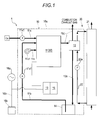
- a fuel cell system 1 includes an electric power generation unit 10 and a hot water storage tank 21.
- the electric power generation unit 10 includes a case 10a, a fuel cell module 11 (30), a heat exchanger 12, a power conversion device 13, a water tank 14, and a control device 15.
- the fuel cell module 11, the heat exchanger 12, the power conversion device 13, the water tank 14, and the control device 15 are accommodated in the case 10a.
- the fuel cell module 11 is configured to include at least a fuel cell device 34 (50) which will be described later. Reforming raw material, reforming water, and cathode air (oxidizer gas) are supplied to the fuel cell module 11. Specifically, the fuel cell module 11 is connected to the other end of a reforming raw material supply pipe 11 a whose one end is connected to a supply source Gs to be supplied with the reforming raw material. The reforming raw material supply pipe 11a is provided with a raw material pump 11a1. Furthermore, the fuel cell module 11 is connected to the other end of a water supply pipe 11 b whose one end is connected to the water tank 14 to be supplied with the reforming water. The water supply pipe 11 b is provided with a reforming water pump 11 b1. The fuel cell module 11 is connected to the other end of a cathode air supply pipe 11c whose one end is connected to a cathode air blower 11 c1 to be supplied with cathode air.
- a fuel cell device 34 50
- the heat exchanger 12 is a heat exchanger to which combustion exhaust gas exhausted from the fuel cell module 11 is supplied and stored hot water from a hot water storage tank 21 are supplied and in which heat exchange is performed between the combustion exhaust gas and the stored hot water.
- the hot water storage tank 21 stores hot water and is connected with a stored hot water circulation line 22 in which the stored hot water is circulated (circulated in a direction denoted by an arrow in Fig. 1 ).
- a stored hot water circulating pump 22a and the heat exchanger 12 are arranged on the stored hot water circulation line 22 in this order from a lower end toward an upper end.
- the heat exchanger 12 is connected with (penetratingly provided with) an exhaust pipe 11 d extending from the fuel cell module 11.
- the heat exchanger 12 is connected with a condensed water supply pipe 12a connected to the water tank 14.
- the combustion exhaust gas from the fuel cell module 11 is introduced into the heat exchanger 12 through the exhaust pipe 11d, subjected to the heat exchange with the stored hot water, cooled down, and the water vapor contained in the combustion exhaust gas is condensed.
- the combustion exhaust gas after being cooled down is discharged to the outside through the exhaust pipe 11 d.
- the condensed water is supplied to the water tank 14 through the condensed water supply pipe 12a.
- the condensed water is purified by ion exchange resin.
- An exhaust heat recovery system 20 is constituted with the heat exchanger 12 described above, the hot water storage tank 21, and the stored hot water circulation line 22.
- the exhaust heat recovery system 20 recovers the exhaust heat of the fuel cell module 11 into the stored hot water so as to be accumulated.
- the power conversion device 13 receives a DC voltage which is output from the fuel cell device 34 as an input, converts the input DC voltage into a predetermined AC voltage, and outputs the predetermined AC voltage to a power source line 16b connected to an AC system power source 16a and an external power load 16c (for example, electrical products).
- the power conversion device 13 receives AC voltage from the system power source 16a through the power source line 16b as an input, converts the AC voltage into a predetermined DC voltage, and outputs the DC voltage to an auxiliary machine (each pump, blower, or the like) or the control device 15. Otherwise, the power conversion device 13 receives a DC voltage of the fuel cell device 34 and outputs the DC voltage to an auxiliary machine (each pump, blower, or the like) or the control device 15.
- the control device 15 drives the auxiliary machine to control the operation of the fuel cell system 1.
- the fuel cell module 11 (30) is a solid oxide fuel cell module.
- the fuel cell module 30 includes a housing 31, an evaporating unit 32, a reforming unit 33, the fuel cell device 34 (50), and a first combustion unit 35 (which corresponds to a combustion unit disclosed here).
- a first combustion unit 35 which corresponds to a combustion unit disclosed here.
- an upper side and a lower side in Fig. 2 are the above and the below of the fuel cell module 30, respectively, and similarly, the left side and the right side in Fig. 2 are the left and the right of the fuel cell module 30, respectively, and the front side and the inner side of a paper surface are the front and the rear of the fuel cell module 30, respectively.
- Respective directions are illustrated by arrows in Fig. 2 to Fig. 6 , Fig. 9 and Fig. 10 .
- the housing 31 is made of conductive metal (for example, alloy steel or carbon steel) in a box shape and is provided with insulating material.
- the evaporating unit 32 and the reforming unit 33 are arranged to be located above the fuel cell device 34.
- the other end of the reforming raw material supply pipe 11a and the other end of the water supply pipe 11 b are connected to the evaporating unit 32 (see Fig. 4 ).
- the evaporating unit 32 is heated by combustion gas to be described later, evaporates the condensed water supplied as reforming water from the water tank 14 through the water supply pipe 11b, and generates water vapor (reforming water vapor), and leads out the water vapor.
- the evaporating unit 32 preheats the reforming raw material supplied through the reforming raw material supply pipe 11a.
- the evaporating unit 32 mixes the water vapor (reforming water vapor) generated by evaporating the reforming water (condensed water) and the preheated reforming raw material to be led out to the reforming unit 33.
- the reforming raw material includes natural gas, a reforming gas fuel such as LPG, and a reforming liquid fuel such as kerosene, gasoline, methanol, or the like, and description will be made on natural gas in the embodiment disclosed
- the reforming unit 33 generates reforming gas from the reforming raw material and the water vapor (reforming water vapor). Specifically, the reforming unit 33 generates reforming gas from the mixed gas (reforming raw material and reforming water vapor) supplied from the evaporating unit 32 and leads out the reforming gas by being supplied with heat required for a reforming reaction of water vapor heated by the combustion gas to be described later.
- the reforming unit 33 is filled with the catalyst (for example, Ru or Ni based catalyst) and mixed gas therein is reacted by the catalyst to be reformed and hydrogen gas and carbon monoxide gas are generated (so-called water vapor reforming reaction).
- the catalyst for example, Ru or Ni based catalyst
- a so-called carbon monoxide shift reaction in which the carbon monoxide gas and the water vapor, that are generated by water vapor reforming reaction, are reacted with each other and respectively converted into hydrogen gas and carbon dioxide gas, occurs.
- the gas (reforming gas) generated as described above is led out to the fuel cell device 34.
- the reforming gas contains hydrogen, carbon monoxide, carbon dioxide, water vapor, unreformed natural gas (methane gas), and the reforming water (water vapor) not used for reforming.
- the water vapor reforming reaction is an endothermic reaction and the carbon monoxide shift reaction is an exothermic reaction.
- the evaporating unit 32 and the reforming unit 33 described above are formed in a casing 40 as illustrated in Fig. 4 .
- the casing 40 is formed in a planar U-shape by a first rectangular parallelepiped 40a and a second rectangular parallelepiped 40b, that are extending along the front-rear direction, and a connecting part 40c that connects rear ends of the rectangular parallelepiped 40a and the rectangular parallelepiped 40b.
- the casing 40 is made of conductive metal (for example, alloy steel or carbon steel).
- the casing 40 is formed in a square section inside of which is a cavity.
- the casing 40 Inside of the casing 40 is partitioned into an evaporating unit casing 41 (which corresponds to a first casing disclosed here) and a reforming unit casing 42 (which corresponds to a second casing disclosed here) by a side wall 40d formed inside of the first rectangular parallelepiped 40a as a boundary therebetween so as to allow gas to pass.
- the evaporating unit 32 is formed in the evaporating unit casing 41 and the reforming unit 33 is formed in the reforming unit casing 42.
- the evaporating unit casing 41 is integrally formed with the reforming unit casing 42.
- the first rectangular parallelepiped 40a is arranged above a first stack 51 a (which will be described later).
- the second rectangular parallelepiped 40b is arranged above a second stack 51 b (which will be described later) (see Fig. 2 to Fig. 4 ).
- the fuel cell device 34 includes, as illustrated in Fig. 2, Fig. 3 , and Fig. 5 , a fuel cell 51, a manifold 52, and an electrode 53.
- the fuel cell device 50 includes two electrodes 53 (see Fig. 5 ).
- the fuel cell 51 generates electric power using the reforming gas and the oxidizer gas.
- the oxidizer gas is, for example, air (cathode air) in the present embodiment.
- the fuel cell according to the present embodiment is a solid oxide fuel cell and uses zirconium oxide which is a kind of solid oxide as an electrolyte. Hydrogen, carbon monoxide, methane gas, or the like are supplied as fuel to a fuel electrode of the fuel cell 51.
- An operating temperature is approximately 400°C to 1000°C.
- the fuel cell 51 as illustrated in Fig. 5 , includes a first stack 51a, a second stack 51b, a stack supporting member 51 c, a current lead-out member 51 d, and a connecting member 51e
- the stacks 51 a and 51 b are configured in such a way that a plurality of cells 51a1 and 51b1 formed with a fuel electrode, an air electrode (oxidizer electrode), and an electrolyte interposed between the electrodes are stacked along the front-rear direction (see Fig. 3 and Fig. 5 ).
- Fuel flow passages 51a2 and 51b2 through which the reforming gas, which is fuel, passes are formed at the fuel electrode sides of the cells 51a1 and 51b1.
- Anode off gas (which will be described later) is led out from the lead-out ports 51a3 and 51b3 of the upper end of the fuel flow passages 51a2 and 51b2 (see Fig. 2 ).
- Air flow passages 51a4 and 51b4 through which air (cathode air) passes are formed at the air electrode sides of the cells 51a1 and 51b1.
- the two stacks 51 a and 51 b are arranged in parallel in the front-rear direction as the direction in which the cells 51a1 and 51 b1 are stacked.
- the stack supporting members 51c are arranged in the front end and the rear end of the stacks 51 a and 51b, respectively, and support the stacks 51 a and 51b, respectively.
- the stack supporting members 51c are made of conductive material to be formed in a planar shape, and are bonded to ends of the stacks 51 a and 51 b by, for example, a conductive adhesive, respectively.
- the current lead-out members 51 d lead out electric current generated by electric power generation of the cells 51a1 and 51b1.
- the current lead-out members 51 d are made of conductive material to be formed in a plate shape extending in the front-rear direction.
- the current lead-out members 51 d are integrally formed with the stack supporting members 51c.
- the connecting member 51e is made of conductive material and connects the current lead-out members 51 d provided in the front ends of the stacks 51 a and 51 b.
- the stacks 51 a and 51 b are arranged on the same end sides of the stacks 51 a and 51 b in a state where polarities become reverse to each other. With this, the connecting member 51e electrically connects the stacks 51 a and 51 b in series.
- the fuel cell 51 is provided on a manifold 52.
- the manifold 52 is formed in a box shape the inside of which is a cavity.
- the reforming gas from the reforming unit 33 is supplied to the manifold 52 through a reforming gas supply pipe 54 as illustrated in Fig. 3 (see an arrow of a broken line).
- the reforming gas supply pipe 54 is made of conductive metal (for example, alloy steel or carbon steel).
- One end (upper end) of the reforming gas supply pipe 54 is connected to the front end part of the reforming unit casing 42 (the second rectangular parallelepiped 40b).
- the other end (lower end) of the reforming gas supply pipe 54 is connected in front of the second stack 51 b in the manifold 52 (see Fig. 5 ).
- the reforming gas from the reforming unit 33 circulates in the inside of the manifold 52 and is led out from the plurality of openings 52a formed on the upper side wall (see an arrow of a solid line).
- the lower ends of the fuel flow passages 51a2 and 51 b2 are connected to the plurality of openings 52a in an airtight manner.
- the reforming gas led out from the plurality of openings 52a is introduced into the fuel flow passages 51a2 and 51b2 from the lower ends thereof and led out from the fuel lead-out ports 51a3 and 51b3 as anode off gas (which will be described later).
- the cathode air (air) is supplied to the air flow passages 51 a4 and 51b4 through the air supply pipe 31a as illustrated by the broken line in Fig. 2 .
- the air supply pipe 31a communicates with the other end of the cathode air supply pipe 11c and leads out the cathode air from the cathode air supply pipe 11c to one end (lower ends) of the air flow passages 51a4 and 51b4.
- the air supply pipe 31 a is made of conductive metal (for example, alloy steel or carbon steel) to be integrally formed with the housing 31.
- the air supply pipe 31 a is formed to be suspended from the inner side of the upper wall of the housing 31 and to be run between the stacks 51 a and 51 b.
- the cathode air is introduced from one end (lower ends) of the air flow passages 51a4 and 51b4 and led out from the other end (upper ends) thereof.
- the other end of the reforming gas supply pipe 54 is connected in the front of the second stack 51 b in the manifold 52 and thus, a distance from the other end of the reforming gas supply pipe 54 to the fuel flow passage 51b2 of the front end part of the second stack 51 b is shortest among the distances from the other end of the reforming gas supply pipe 54 to the respective fuel flow passages 51a2 and 51b2 in the manifold 52.
- Pressure loss inside of the manifold 52 is proportional to the distance and thus, the pressure loss from the other end of the reforming gas supply pipe 54 to the fuel flow passage 51b2 of the front end part of the second stack 51 b is smallest.
- the flow rate of the anode off gas from the lead-out port 51 b3 of the front end part of the second stack 51 b is greater than that of the lead-out port 51a3.
- a distance from the other end of the reforming gas supply pipe 54 to the fuel flow passage 51a2 of the rear end part of the first stack 51 a is longest among the distances from the other end of the reforming gas supply pipe 54 to the respective fuel flow passages 51a2 and 51b2.
- the flow rate of the anode off gas from the lead-out port 51 a3 of the rear end part of the first stack 51 a is smaller than that of the lead-out port 51 b3.
- Electric power generated by the fuel cell 51 is output to the power conversion device 13 through electrodes 53.
- the electrodes 53 are connected to the current lead-out members 51 d each of which is provided on the rear end part of the stacks 51 a and 51 b.
- (chemical formula 1) H 2 + O 2- ⁇ H 2 O + 2e -
- (chemical formula 2) CO + O 2 - ⁇ CO 2 + 2e -
- (chemical formula 3) 1/2O 2 + 2e - ⁇ O 2-
- the first combustion unit 35 burns combustible gas led out from the fuel cell 51 between the evaporating unit 32, the reforming unit 33, and the plurality of lead-out ports 51a3 and 51 b3 for the combustible gas by oxidizer gas as illustrated in Fig. 2 and Fig. 3 .
- the combustible gas is gas which burns, and is reforming gas (anode off gas) led out from the fuel flow passages 51a2 and 51b2 (lead-out ports 51a3 and 51b3) without being used for electric power generation.
- the oxidizer gas is air (cathode air (cathode off gas)) led out from the air flow passage 51a4 and 51 b4 without being used for electric power generation.
- the first combustion unit 35 corresponds to a combustion space in which anode off gas is burned using the oxidizer gas.
- the anode off gas is burned, the combustion gas (flame 36) is generated, and the evaporating unit 32 and the reforming unit 33 are heated by the generated combustion gas.
- the combustion unit 35 includes a left combustion unit 35a and a right combustion unit 35b.
- the left combustion unit 35a as illustrated in Fig. 2 , is arranged between the first rectangular parallelepiped 40a having the evaporating unit 32 therein and the lead-out port 51a3 of the first stack 51 a. With this, the left combustion unit 35a heats a portion of the reforming unit 33 and the evaporating unit 32.
- the right combustion unit 35b is arranged between the second rectangular parallelepiped 40b and the lead-out port 51b3 of the second stack 51 b. With this, the right combustion unit 35b heats a portion of the reforming unit 33.
- the combustion gas heats the inside of the fuel cell module 30 to the operating temperature of the fuel cell 51.
- the anode off gas is burned and combustion exhaust gas is generated.
- the combustion exhaust gas is exhausted from the fuel cell module 30 through the exhaust port 31 b (see Fig. 3 ).
- the first combustion unit temperature sensor 37 is formed in a rod-like shape whose longitudinal direction corresponds to the front-rear direction and detects a temperature of the first combustion unit 35 (right combustion unit 35b).
- the first combustion unit temperature sensor 37 transmits a temperature detection result to the control device 15.
- the first combustion unit temperature sensor 37 as illustrated in Fig. 6 , includes a sensor unit 37a and a sensor unit protection pipe 37b (corresponds to a third casing disclosed here).
- the sensor unit 37a is a sheath thermocouple.
- the sensor unit 37a includes a sheath 37a1, a pair of wires 37a2, and a temperature detection unit 37a3.
- the sheath 37a1 is made of stainless steel having conductivity and is formed in a rod-like shape the inside of which is a cavity.
- the wire 37a2 and the temperature detection unit 37a3 are arranged in the sheath 37a1 and the sheath 37a1 is filled with an insulator such as magnesium powder (not illustrated).
- the temperature detection unit 37a3 is accommodated in one end (rear end) part within the sheath 37a1 and detects a temperature of a portion where the first combustion unit temperature sensor is arranged.
- the temperature detection unit 37a3 is arranged to be located in the front end part of the right combustion unit 35b (see Fig. 5 ) and thus, detects the temperature of the front end part of the right combustion unit 35b.
- the sensor unit protection pipe 37b is made of stainless steel having conductivity and is formed in a rod-like shape the inside of which is a cavity.
- the sensor unit protection pipe 37b accommodates the sensor unit 37a on the inner side thereof. With this, the sensor unit protection pipe 37b protects the sensor unit 37a from the flame 36.
- the sensor unit protection pipe 37b includes a smaller-diameter portion 37b1 located in the tip end part (rear end part) thereof and a larger diameter portion 37b2 located on the front side of the smaller-diameter portion 37b1.
- the inner side surface of the smaller-diameter portion 37b1 is formed to be in contact with the outer surface of the sheath 37a1 of the sensor unit 37a.
- the smaller-diameter portion 37b1 (tip end part (rear end part)) of the sensor unit protection pipe 37b is located in the front end part of the right combustion unit 35b. With this, the temperature of the right combustion unit 35b is reliably transferred to the temperature detection unit 37a3.
- the sensor unit 37a is detachably accommodated in the sensor unit protection pipe 37b. Specifically, the sensor unit 37a is inserted into or drawn out from an opening part 37b3 formed in the rear end of the sensor unit protection pipe 37b. Furthermore, a flange part 37b4 is formed at the peripheral edge of the rear end of the sensor unit protection pipe 37b. A flange part 37a4 formed at the rear end part of the sensor unit 37a is detachably mounted on the flange part 37b4 by a mounting bolt (not illustrated), for example. With this, a maintenance property of the sensor unit 37a is improved.
- the first combustion unit temperature sensor 37 is fixed to the housing 31 through a flange member 37c (corresponds to a support member disclosed here).
- the flange member 37c is formed in a plate shape and is fixed to the housing 31 in an airtight manner by a mounting bolt (not illustrated), for example.
- the sensor unit protection pipe 37b is inserted into a through hole 37c1 of the flange member 37c by penetrating therethrough and is fixed in an airtight manner by a silicon-base adhesive, a ceramic-based adhesive, or the like, for example.
- the firing-up apparatus 38 performs discharge to thereby ignite the combustible gas (anode off gas) and fire up the first combustion unit 35. Ignition is a phenomena of initiating a combustible target (anode off gas) to be caught on fire. Firing up is that a target (first combustion unit 35) is engulfed in flame in a state where the flame is continuous (combustion state).
- the firing-up apparatus 38 includes an electrode support member 38a, a discharge electrode 38b, and a grounding electrode 38c.
- the electrode support member 38a supports the discharge electrode 38b.
- the electrode support member 38a is made of insulating material (for example, alumina) and is formed in a rod-like shape whose longitudinal direction corresponds to the front-rear direction.
- the electrode support member 38a is inserted into a through hole 37c2 of the flange member 37c by penetrating therethrough and is fixed thereto in an airtight manner by a silicon-based adhesive or a ceramic-based adhesive, for example.
- the electrode support member 38a is fixed in parallel with the first combustion unit temperature sensor 37 along the longitudinal direction.
- a through hole 38a1 which penetrates through the electrode support member 38a along the longitudinal direction is formed in the electrode support member 38a.
- the discharge electrode 38b performs discharge between the discharge electrode 38b and the grounding electrode 38c.
- the discharge electrode 38b is made of alloy steel having conductivity and is formed in a rod-like shape.
- the alloy steel is, for example, high-temperature and heat resistant Fe-Cr-Al based alloy for electric-heating (product name: YSS-SYTT).
- the discharge electrode 38b is configured in such a way that one end part thereof is bent and thus one end (rear end) thereof is directed toward the sensor unit protection pipe 37b. With this, a distance to one end of the discharge electrode 38b among the distances to the sensor unit protection pipe 37b is shortest in the discharge electrode 38b.
- the discharge electrode 38b is arranged to penetrate through the through hole 38a1 and is fixed in an airtight manner by silicon-based sealing material or epoxy-based sealing material 38d filled in the inner side of the through hole 38a1, for example. With this, the discharge electrode 38b is fixed in parallel with the first combustion unit temperature sensor 37 along the longitudinal direction.
- the discharge electrode 38b is configured in such a way that one end part (rear end part) thereof is located at the front end part of the right combustion unit 35b (see Fig. 5 ). One end of the discharge electrode 38b is located above the lead-out port 51 b3 of the front end part of the second stack 51 b (see Fig. 5 ).
- the other end part (front end part) of the discharge electrode 38b is electrically connected to a power source apparatus Pw (corresponds to a power source disclosed here).
- the power source apparatus Pw supplies predetermined electrical power to the discharge electrode 38b according to a control command by the control device 15.
- the grounding electrode 38c is formed by a member capable of being installed in the first combustion unit 35.
- the grounding electrode 38c is formed by the sensor unit protection pipe 37b in the embodiment disclosed here.
- the sensor unit protection pipe 37b has conductivity as described above and is grounded through an electric wire (not illustrated), for example.
- discharge is performed between one end of the discharge electrode 38b and the grounding electrode 38c due to the potential difference generated between the discharge electrode 38b and the grounding electrode 38c.
- One end part of the discharge electrode 38b and the tip end part of the grounding electrode 38c are arranged in the front end part of the right combustion unit 35b.
- the sensor unit protection pipe 37b corresponds to a member capable of being installed in the first combustion unit 35 disclosed here in the embodiment disclosed here.
- the flow rate of the anode off gas led out from the lead-out port 51 b3 of the front end part of the second stack 51 b is greater than that of other lead-out ports 51 a3 and 51b3 and thus, a flow rate of the anode off gas led out from the front end part of the right combustion unit 35b is greater among other components of the first combustion unit 35. That is, the firing-up apparatus 38 ignites the anode off gas led out from the lead-out port 51 b3, through which a greater flow rate of the anode off gas is led out, of the plurality of lead-out ports 51 a3 and 51b3. With this, flame 36 is generated, the flame 36 moves, and the first combustion unit 35 is fired up in its entirety.
- the housing 31 includes a second combustion unit 39 in an exhaust port 31b as illustrated in Fig. 3 .
- the combustible gas (hereinafter, referred to as unburned combustible gas) which is unburned by the first combustion unit 35 is introduced, is burned, and is led out.
- the unburned combustible gas is, for example, hydrogen, methane gas, carbon monoxide, or the like.
- the second combustion unit 39 is configured by a combustion catalyst which promotes burning of the unburned combustible gas (for example, ceramic honeycomb catalyst or metal honeycomb noble metal catalyst).
- a combustion catalyst heater 39a and a second combustion unit temperature sensor 39b are provided in the second combustion unit 39.
- the combustion catalyst heater 39a heats the combustion catalyst which promotes burning of the unburned combustible gas.
- the combustion catalyst heater 39a heats the combustion catalyst to a catalyst activating temperature.
- the combustion catalyst heater 39a is an alternating current heater (AC heater: AC auxiliary machine) that heats the combustion catalyst by AC current according to instruction from the control device 15.
- the second combustion unit temperature sensor 39b detects a temperature of the second combustion unit 39. Specifically, the second combustion unit temperature sensor 39b detects the temperature of a location at which the second combustion unit temperature sensor 39b is arranged in the second combustion unit 39. The second combustion unit temperature sensor 39b transmits the temperature detection result to the control device 15.
- the control device 15 controls at least the fuel cell 51.
- the control device 15, as illustrated in Fig. 7 is connected with respective temperature sensors 37 and 39b, respective pumps 11a1, 11 b1, and 22a, the cathode air blower 11 c1, the firing-up apparatus 38, and the combustion catalyst heater 39a.
- the control device 15 starts a startup operation in a case where a start switch (not illustrated) is depressed to start operation or operation is started according to an operation plan.
- the control device 15 activates the auxiliary machine. Specifically, the control device 15 activates the pumps 11a1 and 11b1 and starts supplying of the reforming raw material and the reforming water to the evaporating unit 32. As described above, the mixed gas is generated in the evaporating unit 32 and the mixed gas is supplied to the reforming unit 33. The reforming gas is generated from the supplied mixed gas in the reforming unit 33 and the reforming gas is supplied to the fuel cell 51.
- the control device 15 performs discharge by using the firing-up apparatus 38. Specifically, the control device 15 allows electrical power from the power source apparatus Pw to be supplied to the discharge electrode 38b to thereby perform discharge between the discharge electrode 38b and the grounding electrode 38c.
- the reforming gas which is the combustible gas led out from the lead-out port 51 b3 is ignited and thus the first combustion unit 35 is fired up.
- the detection temperature detected by the first combustion unit temperature sensor 37 becomes greater than or equal to a first detection temperature (for example, 600°C)
- the control device 15 determines that the first combustion unit 35 is fired up. If an internal temperature of the reforming unit 33 becomes greater than or equal to an activation temperature (for example, 400°C), the startup operation is finished, and electric power generation operation is started.
- the control device 15 controls the auxiliary device such that electric power generated by the fuel cell 51 becomes power consumption of an external power load 16c during the electric power generation operation and supplies the reforming raw material and the cathode air (air) to the fuel cell module 30 and the fuel cell 51.
- the shortage of the power capacity is supplemented by receiving electric power from the system power supply 16a.
- the fuel cell system 1 includes the fuel cell 51 that generates electric power using reforming gas and oxidizer gas, the evaporating unit 32 that generates water vapor from reforming water, the reforming unit 33 that generates reforming gas from the reforming raw material supplied from a supply source Gs and the water vapor supplied from the evaporating unit 32 and supplies the reforming gas to the fuel cell 51, the first combustion unit 35 (right combustion unit 35b) that corresponds to a combustion space in which combustible gas (anode off gas) led out from the fuel cell 51 is burned between the evaporating unit 32, the reforming unit 33, and the plurality of lead-out ports 51a3 and 51b3 of the combustible gas, and a firing-up apparatus 38 that performs discharge to ignite the combustible gas and fire up the first combustion unit 35.
- the first combustion unit 35 right combustion unit 35b
- a firing-up apparatus 38 that performs discharge to ignite the combustible gas and fire up the first combustion unit 35.
- the firing-up apparatus 38 includes the grounding electrode 38c and the discharge electrode 38b arranged in the first combustion unit 35 and performs discharge between the grounding electrode 38c and the discharge electrode 38b using the electric power supplied from the power source apparatus Pw, and the grounding electrode 38c is formed by a member capable of being installed in the first combustion unit 35.
- the evaporating unit 32 includes the conductive evaporating unit casing 41 and the reforming unit 33 includes the conductive reforming unit casing 42.
- the fuel cell system 1 further includes the first combustion unit temperature sensor 37 including the temperature detection unit 37a3 that detects the temperature of the first combustion unit 35 and the conductive sensor unit protection pipe 37b in which the temperature detection unit 37a3 is accommodated.
- the grounding electrode 38c is the sensor unit protection pipe 37b.
- the grounding electrode 38c is formed by the sensor unit protection pipe 37b and the discharge electrode 38b is arranged in the first combustion unit 35 and thus, the firing-up apparatus 38 may stably fire up the first combustion unit 35. It is possible to further reduce the number of components of the firing-up apparatus 38 and the fuel cell system 1 compared to a case where the grounding electrode 38c is formed by a rod-like conductor as in the firing-up apparatus of the related art. Therefore, it is possible to achieve cost reduction in the fuel cell system 1.
- the sensor unit protection pipe 37b and the discharge electrode 38b are formed in a rod-like shape
- the firing-up apparatus 38 further includes the flange member 37c that supports the sensor unit protection pipe 37b and the discharge electrode 38b to be parallel with each other along the longitudinal direction
- the grounding electrode 38c is the sensor unit protection pipe 37b.
- the rod-like shaped sensor unit protection pipe 37b that corresponds to the grounding electrode 38c and the rod-like shaped discharge electrode 38b are arranged in parallel with each other in the flange member 37c and thus, it is possible to improve the accuracy of a distance between the electrodes compared to a case where the grounding electrode 38c and the discharge electrode 38b are respectively arranged in separate members.
- a discharge condition may be maintained to be constant and thus, stabilization of ignition of combustible gas may be achieved.
- the firing-up apparatus 38 ignites the combustible gas led out from the lead-out port 51b3, through which a greater amount of the combustible gas (anode off gas) is led out, of the plurality of lead-out ports 51 a3 and 51 b3.
- the firing-up apparatus 38 it is easy for the firing-up apparatus 38 to ignite the combustible gas compared to a case where the combustible gas is led out from the lead-out port 51a3, through which a relatively smaller amount of the combustible gas is led out, of the plurality of lead-out ports 51a3 and 51b3. Accordingly, the relatively simple ignition of combustible gas may be performed.
- control device 15 further includes a blow-off determination unit 15a (see Fig. 8 ) compared to the first embodiment described above.
- the blow-off determination unit 15a determines whether the first combustion unit 35 is blown off up or not. Blowing off of the first combustion unit 35 is that a combustion state of at least a portion of the first combustion unit 35 is ended.
- the first combustion unit 35 is in the combustion state during the startup operation and the electric power generation operation of the fuel cell system 1, in a case where at least a portion of the first combustion unit 35 is blown off, the flow rate of the unburned combustible gas described above to be burned by the second combustion unit 39 is increased and thus, the temperature of the second combustion unit 39 is increased.
- the blow-off determination unit 15a determines that the first combustion unit 35 is blown off.
- the second determination temperature is derived in advance by being measured by experiments or the like.
- the control device 15 causes the firing-up apparatus 38 to perform discharge to thereby reignite the combustible gas (anode off gas) and re-fire up the first combustion unit 35.
- the blow-off determination unit 15a determines that the first combustion unit 35 is not blown off.
- the second embodiment is different from the first embodiment described above in that the firing-up apparatus 38 is arranged in the rear end part of the left combustion unit 35a.
- the firing-up apparatus 38 is arranged in the rear end part of the left combustion unit 35a.
- one end part (front end part) of the discharge electrode 38b and the tip end part (front end part) of the grounding electrode 38c (sensor unit protection pipe 37b) are fixed to be located at the rear end part of the left combustion unit 35a.
- One end of the discharge electrode 38b is located above the lead-out port 51 a3 of the rear end part of the first stack 51 a.
- the flow rate of anode off gas led out from the lead-out port 51 a3 of the rear end part of the first stack 51 a is smaller compared to the other lead-out ports 51 a3 and 51b3 and thus, the flow rate of the anode off gas led out from the rear end part of the left combustion unit 35a of the first combustion unit 35 is smaller. That is, the firing-up apparatus 38 ignites the anode off gas led out from the lead-out port 51a3, through which a smaller amount of the anode off gas is led out, of the plurality of lead-out ports 51a3 and 51b3.
- Blowing off of the first combustion unit 35 occurs relatively easily in a portion above the lead-out ports 51a3 and 51b3, through which a smaller amount of the anode off gas is led out, of the first combustion unit 35. Accordingly, the firing-up apparatus 38 performs a discharge in the portion where blowing off of the first combustion unit 35 occurs relatively easily.
- the firing-up apparatus 38 ignites the combustible gas (anode off gas) led out from the lead-out port 51a3, through which a smaller amount of the combustible gas is led out, of the plurality of lead-out ports 51a3 and 51b3.
- the firing-up apparatus 38 may perform discharge in the portion where blowing off of the first combustion unit 35 relatively easily occur.
- the firing-up apparatus 38 may perform discharge in the portion where blowing off of the first combustion unit 35 relatively easily occur.
- a portion of the first combustion unit 35 is blown off in a space that is formed between the lead-out port 51a3, through which a relatively smaller amount of the combustible gas is allowed to lead out, and the reforming unit casing 42, and that corresponds to the portion where blowing off of the first combustion unit 35 relatively easily occur, it is possible to relatively easily reignite the combustible gas.
- the fuel cell system disclosed here is not limited thereto, and may adopt other configuration.
- the grounding electrode 38c is configured by the sensor unit protection pipe 37b
- the grounding electrode 38c may be configured by one of the evaporating unit casing 41 and the reforming unit casing 42, instead.
- one of the evaporating unit casing 41 and the reforming unit casing 42 is grounded and as illustrated in Fig. 10 , one end part of the discharge electrode 38b is bent toward one of the evaporating unit casing 41 and the reforming unit casing 42.
- one of the evaporating unit casing 41 and the reforming unit casing 42 corresponds to a member capable of being installed in the first combustion unit 35 according to the embodiment disclosed here.
- the grounding electrode 38c may be configured by the housing 31.
- the grounding electrode 38c may be configured by the air supply pipe 31 a illustrated in Fig. 2 .
- the air supply pipe 31a may be formed by being separated from the housing 31 to configure the grounding electrode 38c.
- the reforming gas supply pipe 54 may also be formed to function as the discharge electrode 38b.
- the air supply pipe 31a or the reforming gas supply pipe 54 corresponds to a member capable of being installed in the first combustion unit 35 according to the embodiment disclosed here.
- the grounding electrode 38c and the discharge electrode 38b may be fixed to the same member.
- the grounding electrode 38c and the discharge electrode 38b may be fixed to the cover member. In this case, it is possible to improve the accuracy of the distance between the electrodes.
- the grounding electrode 38c may be formed by the rod material having conductivity like a grounding electrode138c of the firing-up apparatus 138 as illustrated in Fig. 11 , instead of the sensor unit protection pipe 37b, in the embodiments described above.
- a discharge electrode 138b penetrates through a through hole 138a1 and the grounding electrode 138c penetrates through the through hole 138a2.
- the discharge electrode 138b and the grounding electrode 138c are fixed in an air tight manner by silicon-based sealing material 138d or epoxy-based sealing material filled in the inner side of the through holes 138a1 and 138a2, for example.
- the grounding electrode 138c is made of alloy steel having conductivity and is formed in a rod-like shape.
- the alloy steel is, for example, high-temperature and heat resistant Fe-Cr-Al based alloy for electric-heating (product name: YSS-SYTT).
- the firing-up apparatus 138 may be fixed to the housing 31 with a separate flange member (not illustrated) from the flange member 37c that fixes the first combustion unit temperature sensor 37. In this case, the firing-up apparatus 138 and the first combustion unit temperature sensor 37 may not be arranged in parallel with each other.
- the first combustion unit temperature sensor 37 includes the sensor unit protection pipe 37b
- the first combustion unit temperature sensor 37 may not include the sensor unit protection pipe 37b, instead.
- the grounding electrode 38c is configured by the sheath 37a1. That is, in this case, the sheath 37a1 corresponds to a third casing disclosed here. In this case, the sheath 37a1 is fixed to the through hole 37c1 of the flange member 37c.
- a portion where blowing off of the first combustion unit 35 easily occurs is used as a portion where a smaller lead-out amount of the combustible gas (anode off gas) is generated
- a portion where a flow speed of the anode off gas is high may be used, instead.
- the firing-up apparatus 38 ignites the anode off gas led out from the portion where the flow speed of the anode off gas is high.
- the lead-out ports 51a3 and 51b3 are formed on the upper end of the fuel flow passage of the fuel cell 51, the lead-out ports 51a3 and 51b3 may be formed to be separated from the fuel cell 51 instead.
- the fuel cell system 1 may further include a combustible circulation pipe (not illustrated) whose one end is connected to the upper ends of the fuel flow passages 51a2 and 51b2 and the other end thereof forms the lead-out ports 51a3 and 51b3.
- the lead-out ports 51a3 and 51b3 may be formed on a portion other than the upper end of the fuel cell 51 and thus, a degree of freedom for a position of the first combustion unit 35, a shape, and an arrangement position of the evaporating unit 32 and the reforming unit 33 is increased.
- the shape of the casing 40, the positional relationship between the evaporating unit casing 41, the reforming unit casing 42, and the fuel cell 51 (stacks 51 a and 51 b), the arrangement positions of the evaporating unit 32 and the reforming unit 33, the located position of the reforming gas supply pipe 54, and the arrangement position or number of the firing-up apparatus 38 and the first combustion unit temperature sensor 37 may be changed in a range without departing from a gist of the embodiment disclosed here.
- a fuel cell system (1) includes: a fuel cell (51) that generates electric power using reforming gas and oxidizer gas; an evaporating unit (32) that generates water vapor from reforming water; a reforming unit (33) that generates the reforming gas from a reforming raw material supplied from a supply source (Gs) and the water vapor supplied from the evaporating unit; a reforming gas supply pipe (54) that supplies the reforming gas to a fuel flow passage (51 a2, 51 b2) of the fuel cell; a combustion unit (35) that corresponds to a combustion space in which combustible gas led out from the fuel cell is burned between the evaporating unit, the reforming unit, and a plurality of lead-out ports (51a3, 51b3) for the combustible gas; and a firing-up apparatus (38) that performs discharge to ignite the combustible gas and fire up the combustion unit.
Landscapes
- Life Sciences & Earth Sciences (AREA)
- Engineering & Computer Science (AREA)
- Manufacturing & Machinery (AREA)
- Sustainable Development (AREA)
- Sustainable Energy (AREA)
- Chemical & Material Sciences (AREA)
- Chemical Kinetics & Catalysis (AREA)
- Electrochemistry (AREA)
- General Chemical & Material Sciences (AREA)
- Fuel Cell (AREA)
- Hydrogen, Water And Hydrids (AREA)
Applications Claiming Priority (1)
| Application Number | Priority Date | Filing Date | Title |
|---|---|---|---|
| JP2015182205A JP6597100B2 (ja) | 2015-09-15 | 2015-09-15 | 燃料電池システム |
Publications (2)
| Publication Number | Publication Date |
|---|---|
| EP3145013A1 true EP3145013A1 (de) | 2017-03-22 |
| EP3145013B1 EP3145013B1 (de) | 2017-11-08 |
Family
ID=56740154
Family Applications (1)
| Application Number | Title | Priority Date | Filing Date |
|---|---|---|---|
| EP16184893.2A Active EP3145013B1 (de) | 2015-09-15 | 2016-08-19 | Brennstoffzellensystem |
Country Status (2)
| Country | Link |
|---|---|
| EP (1) | EP3145013B1 (de) |
| JP (1) | JP6597100B2 (de) |
Cited By (3)
| Publication number | Priority date | Publication date | Assignee | Title |
|---|---|---|---|---|
| AT520482A1 (de) * | 2017-10-03 | 2019-04-15 | Avl List Gmbh | Verfahren zum schnellen Aufheizen eines Brennstoffzellensystems |
| CN110649295A (zh) * | 2019-09-30 | 2020-01-03 | 西安新衡科测控技术有限责任公司 | 一种基于ht-pem甲醇水燃料电池mimo系统的控制方法 |
| CN111912251A (zh) * | 2020-07-14 | 2020-11-10 | 湖南人文科技学院 | 一种质子交换膜燃料电池余热利用系统 |
Families Citing this family (4)
| Publication number | Priority date | Publication date | Assignee | Title |
|---|---|---|---|---|
| JP6762112B2 (ja) * | 2016-03-10 | 2020-09-30 | 京セラ株式会社 | 燃料電池用改質器、燃料電池モジュールおよびモジュール収容装置 |
| JP6867209B2 (ja) * | 2017-03-29 | 2021-04-28 | 京セラ株式会社 | セルスタック装置、モジュールおよびモジュール収容装置 |
| WO2018199251A1 (ja) * | 2017-04-26 | 2018-11-01 | 京セラ株式会社 | 発電装置、制御装置、および制御プログラム |
| JP7334627B2 (ja) | 2020-01-16 | 2023-08-29 | 株式会社アイシン | 燃料電池システム |
Citations (4)
| Publication number | Priority date | Publication date | Assignee | Title |
|---|---|---|---|---|
| EP1411573A2 (de) * | 2002-10-16 | 2004-04-21 | Matsushita Electric Industrial Co., Ltd. | Brenner, Wasserstoffgenerator und Brennstoffzellenstromerzeugungssystem |
| US20060039854A1 (en) * | 2004-08-19 | 2006-02-23 | Korea Institute Of Science And Technology | Catalyst for partial oxidation reforming of fuel and fuel reforming apparatus and method using the catalyst |
| JP2013065506A (ja) | 2011-09-20 | 2013-04-11 | Toto Ltd | 燃料電池装置 |
| JP2013171636A (ja) | 2012-02-17 | 2013-09-02 | Toto Ltd | 燃料電池装置 |
-
2015
- 2015-09-15 JP JP2015182205A patent/JP6597100B2/ja active Active
-
2016
- 2016-08-19 EP EP16184893.2A patent/EP3145013B1/de active Active
Patent Citations (4)
| Publication number | Priority date | Publication date | Assignee | Title |
|---|---|---|---|---|
| EP1411573A2 (de) * | 2002-10-16 | 2004-04-21 | Matsushita Electric Industrial Co., Ltd. | Brenner, Wasserstoffgenerator und Brennstoffzellenstromerzeugungssystem |
| US20060039854A1 (en) * | 2004-08-19 | 2006-02-23 | Korea Institute Of Science And Technology | Catalyst for partial oxidation reforming of fuel and fuel reforming apparatus and method using the catalyst |
| JP2013065506A (ja) | 2011-09-20 | 2013-04-11 | Toto Ltd | 燃料電池装置 |
| JP2013171636A (ja) | 2012-02-17 | 2013-09-02 | Toto Ltd | 燃料電池装置 |
Cited By (5)
| Publication number | Priority date | Publication date | Assignee | Title |
|---|---|---|---|---|
| AT520482A1 (de) * | 2017-10-03 | 2019-04-15 | Avl List Gmbh | Verfahren zum schnellen Aufheizen eines Brennstoffzellensystems |
| AT520482B1 (de) * | 2017-10-03 | 2019-11-15 | Avl List Gmbh | Verfahren zum schnellen Aufheizen eines Brennstoffzellensystems |
| CN110649295A (zh) * | 2019-09-30 | 2020-01-03 | 西安新衡科测控技术有限责任公司 | 一种基于ht-pem甲醇水燃料电池mimo系统的控制方法 |
| CN110649295B (zh) * | 2019-09-30 | 2022-05-20 | 西安新衡科测控技术有限责任公司 | 一种基于ht-pem甲醇水燃料电池mimo系统的控制方法 |
| CN111912251A (zh) * | 2020-07-14 | 2020-11-10 | 湖南人文科技学院 | 一种质子交换膜燃料电池余热利用系统 |
Also Published As
| Publication number | Publication date |
|---|---|
| EP3145013B1 (de) | 2017-11-08 |
| JP2017059375A (ja) | 2017-03-23 |
| JP6597100B2 (ja) | 2019-10-30 |
Similar Documents
| Publication | Publication Date | Title |
|---|---|---|
| EP3145013B1 (de) | Brennstoffzellensystem | |
| JP5179520B2 (ja) | 燃料電池装置 | |
| JP6247671B2 (ja) | 燃料電池モジュール | |
| JP6510262B2 (ja) | 燃料電池モジュール及びその運転方法 | |
| JP2009283188A (ja) | 固体酸化物形燃料電池およびその起動方法 | |
| JP2008135351A (ja) | 発電装置 | |
| JP2010267394A (ja) | 発電装置 | |
| EP3113269B1 (de) | Brennstoffzellensystem | |
| JP5409166B2 (ja) | 燃料電池モジュールおよび燃料電池装置 | |
| JP6701804B2 (ja) | 燃料電池システム | |
| JP5995183B2 (ja) | 燃料電池装置 | |
| JP5548534B2 (ja) | 発電装置 | |
| EP2624347B1 (de) | Festoxid-brennstoffzelle | |
| EP3104443B1 (de) | Brennstoffzellensystem | |
| JP6215744B2 (ja) | 熱交換器、及び、燃料電池システム | |
| JP6960610B2 (ja) | 燃料電池システムおよび燃料電池システムの運転方法 | |
| JP2020098749A (ja) | 燃料電池モジュール | |
| JP6444197B2 (ja) | 燃料電池モジュール | |
| JP6450202B2 (ja) | 燃料電池モジュール | |
| JP6803547B2 (ja) | 高温動作型燃料電池システムおよび高温動作型燃料電池システムの運転方法 | |
| JP6015907B2 (ja) | 固体酸化物型燃料電池 | |
| JP6172616B2 (ja) | 固体酸化物型燃料電池システム | |
| JP5552380B2 (ja) | 発電装置 | |
| JP2016157571A (ja) | 固体酸化物型燃料電池 | |
| JP2009076275A (ja) | 燃料電池モジュール |
Legal Events
| Date | Code | Title | Description |
|---|---|---|---|
| PUAI | Public reference made under article 153(3) epc to a published international application that has entered the european phase |
Free format text: ORIGINAL CODE: 0009012 |
|
| 17P | Request for examination filed |
Effective date: 20161227 |
|
| AK | Designated contracting states |
Kind code of ref document: A1 Designated state(s): AL AT BE BG CH CY CZ DE DK EE ES FI FR GB GR HR HU IE IS IT LI LT LU LV MC MK MT NL NO PL PT RO RS SE SI SK SM TR |
|
| AX | Request for extension of the european patent |
Extension state: BA ME |
|
| RIC1 | Information provided on ipc code assigned before grant |
Ipc: H01M 8/04223 20160101ALN20170412BHEP Ipc: H01M 8/124 20160101ALN20170412BHEP Ipc: H01M 8/04007 20160101ALN20170412BHEP Ipc: H01M 8/0612 20160101AFI20170412BHEP Ipc: H01M 8/04701 20160101ALI20170412BHEP Ipc: H01M 8/04014 20160101ALN20170412BHEP |
|
| GRAJ | Information related to disapproval of communication of intention to grant by the applicant or resumption of examination proceedings by the epo deleted |
Free format text: ORIGINAL CODE: EPIDOSDIGR1 |
|
| GRAP | Despatch of communication of intention to grant a patent |
Free format text: ORIGINAL CODE: EPIDOSNIGR1 |
|
| INTG | Intention to grant announced |
Effective date: 20170531 |
|
| GRAS | Grant fee paid |
Free format text: ORIGINAL CODE: EPIDOSNIGR3 |
|
| GRAJ | Information related to disapproval of communication of intention to grant by the applicant or resumption of examination proceedings by the epo deleted |
Free format text: ORIGINAL CODE: EPIDOSDIGR1 |
|
| GRAL | Information related to payment of fee for publishing/printing deleted |
Free format text: ORIGINAL CODE: EPIDOSDIGR3 |
|
| GRAR | Information related to intention to grant a patent recorded |
Free format text: ORIGINAL CODE: EPIDOSNIGR71 |
|
| INTC | Intention to grant announced (deleted) | ||
| GRAA | (expected) grant |
Free format text: ORIGINAL CODE: 0009210 |
|
| RIC1 | Information provided on ipc code assigned before grant |
Ipc: H01M 8/0612 20160101AFI20170911BHEP Ipc: H01M 8/04701 20160101ALI20170911BHEP Ipc: H01M 8/04014 20160101ALN20170911BHEP Ipc: H01M 8/04007 20160101ALN20170911BHEP Ipc: H01M 8/124 20160101ALN20170911BHEP Ipc: H01M 8/04223 20160101ALN20170911BHEP |
|
| AK | Designated contracting states |
Kind code of ref document: B1 Designated state(s): AL AT BE BG CH CY CZ DE DK EE ES FI FR GB GR HR HU IE IS IT LI LT LU LV MC MK MT NL NO PL PT RO RS SE SI SK SM TR |
|
| INTG | Intention to grant announced |
Effective date: 20171002 |
|
| REG | Reference to a national code |
Ref country code: GB Ref legal event code: FG4D |
|
| REG | Reference to a national code |
Ref country code: CH Ref legal event code: EP Ref country code: AT Ref legal event code: REF Ref document number: 944974 Country of ref document: AT Kind code of ref document: T Effective date: 20171115 |
|
| REG | Reference to a national code |
Ref country code: IE Ref legal event code: FG4D |
|
| REG | Reference to a national code |
Ref country code: DE Ref legal event code: R096 Ref document number: 602016000749 Country of ref document: DE |
|
| REG | Reference to a national code |
Ref country code: NL Ref legal event code: MP Effective date: 20171108 |
|
| REG | Reference to a national code |
Ref country code: LT Ref legal event code: MG4D |
|
| REG | Reference to a national code |
Ref country code: AT Ref legal event code: MK05 Ref document number: 944974 Country of ref document: AT Kind code of ref document: T Effective date: 20171108 |
|
| PG25 | Lapsed in a contracting state [announced via postgrant information from national office to epo] |
Ref country code: FI Free format text: LAPSE BECAUSE OF FAILURE TO SUBMIT A TRANSLATION OF THE DESCRIPTION OR TO PAY THE FEE WITHIN THE PRESCRIBED TIME-LIMIT Effective date: 20171108 Ref country code: SE Free format text: LAPSE BECAUSE OF FAILURE TO SUBMIT A TRANSLATION OF THE DESCRIPTION OR TO PAY THE FEE WITHIN THE PRESCRIBED TIME-LIMIT Effective date: 20171108 Ref country code: ES Free format text: LAPSE BECAUSE OF FAILURE TO SUBMIT A TRANSLATION OF THE DESCRIPTION OR TO PAY THE FEE WITHIN THE PRESCRIBED TIME-LIMIT Effective date: 20171108 Ref country code: NL Free format text: LAPSE BECAUSE OF FAILURE TO SUBMIT A TRANSLATION OF THE DESCRIPTION OR TO PAY THE FEE WITHIN THE PRESCRIBED TIME-LIMIT Effective date: 20171108 Ref country code: LT Free format text: LAPSE BECAUSE OF FAILURE TO SUBMIT A TRANSLATION OF THE DESCRIPTION OR TO PAY THE FEE WITHIN THE PRESCRIBED TIME-LIMIT Effective date: 20171108 Ref country code: NO Free format text: LAPSE BECAUSE OF FAILURE TO SUBMIT A TRANSLATION OF THE DESCRIPTION OR TO PAY THE FEE WITHIN THE PRESCRIBED TIME-LIMIT Effective date: 20180208 |
|
| PG25 | Lapsed in a contracting state [announced via postgrant information from national office to epo] |
Ref country code: RS Free format text: LAPSE BECAUSE OF FAILURE TO SUBMIT A TRANSLATION OF THE DESCRIPTION OR TO PAY THE FEE WITHIN THE PRESCRIBED TIME-LIMIT Effective date: 20171108 Ref country code: AT Free format text: LAPSE BECAUSE OF FAILURE TO SUBMIT A TRANSLATION OF THE DESCRIPTION OR TO PAY THE FEE WITHIN THE PRESCRIBED TIME-LIMIT Effective date: 20171108 Ref country code: BG Free format text: LAPSE BECAUSE OF FAILURE TO SUBMIT A TRANSLATION OF THE DESCRIPTION OR TO PAY THE FEE WITHIN THE PRESCRIBED TIME-LIMIT Effective date: 20180208 Ref country code: GR Free format text: LAPSE BECAUSE OF FAILURE TO SUBMIT A TRANSLATION OF THE DESCRIPTION OR TO PAY THE FEE WITHIN THE PRESCRIBED TIME-LIMIT Effective date: 20180209 Ref country code: HR Free format text: LAPSE BECAUSE OF FAILURE TO SUBMIT A TRANSLATION OF THE DESCRIPTION OR TO PAY THE FEE WITHIN THE PRESCRIBED TIME-LIMIT Effective date: 20171108 Ref country code: LV Free format text: LAPSE BECAUSE OF FAILURE TO SUBMIT A TRANSLATION OF THE DESCRIPTION OR TO PAY THE FEE WITHIN THE PRESCRIBED TIME-LIMIT Effective date: 20171108 Ref country code: IS Free format text: LAPSE BECAUSE OF FAILURE TO SUBMIT A TRANSLATION OF THE DESCRIPTION OR TO PAY THE FEE WITHIN THE PRESCRIBED TIME-LIMIT Effective date: 20180308 |
|
| PG25 | Lapsed in a contracting state [announced via postgrant information from national office to epo] |
Ref country code: DK Free format text: LAPSE BECAUSE OF FAILURE TO SUBMIT A TRANSLATION OF THE DESCRIPTION OR TO PAY THE FEE WITHIN THE PRESCRIBED TIME-LIMIT Effective date: 20171108 Ref country code: SK Free format text: LAPSE BECAUSE OF FAILURE TO SUBMIT A TRANSLATION OF THE DESCRIPTION OR TO PAY THE FEE WITHIN THE PRESCRIBED TIME-LIMIT Effective date: 20171108 Ref country code: CZ Free format text: LAPSE BECAUSE OF FAILURE TO SUBMIT A TRANSLATION OF THE DESCRIPTION OR TO PAY THE FEE WITHIN THE PRESCRIBED TIME-LIMIT Effective date: 20171108 Ref country code: EE Free format text: LAPSE BECAUSE OF FAILURE TO SUBMIT A TRANSLATION OF THE DESCRIPTION OR TO PAY THE FEE WITHIN THE PRESCRIBED TIME-LIMIT Effective date: 20171108 Ref country code: CY Free format text: LAPSE BECAUSE OF FAILURE TO SUBMIT A TRANSLATION OF THE DESCRIPTION OR TO PAY THE FEE WITHIN THE PRESCRIBED TIME-LIMIT Effective date: 20171108 |
|
| REG | Reference to a national code |
Ref country code: DE Ref legal event code: R097 Ref document number: 602016000749 Country of ref document: DE |
|
| PG25 | Lapsed in a contracting state [announced via postgrant information from national office to epo] |
Ref country code: PL Free format text: LAPSE BECAUSE OF FAILURE TO SUBMIT A TRANSLATION OF THE DESCRIPTION OR TO PAY THE FEE WITHIN THE PRESCRIBED TIME-LIMIT Effective date: 20171108 Ref country code: IT Free format text: LAPSE BECAUSE OF FAILURE TO SUBMIT A TRANSLATION OF THE DESCRIPTION OR TO PAY THE FEE WITHIN THE PRESCRIBED TIME-LIMIT Effective date: 20171108 Ref country code: SM Free format text: LAPSE BECAUSE OF FAILURE TO SUBMIT A TRANSLATION OF THE DESCRIPTION OR TO PAY THE FEE WITHIN THE PRESCRIBED TIME-LIMIT Effective date: 20171108 Ref country code: RO Free format text: LAPSE BECAUSE OF FAILURE TO SUBMIT A TRANSLATION OF THE DESCRIPTION OR TO PAY THE FEE WITHIN THE PRESCRIBED TIME-LIMIT Effective date: 20171108 |
|
| PLBE | No opposition filed within time limit |
Free format text: ORIGINAL CODE: 0009261 |
|
| STAA | Information on the status of an ep patent application or granted ep patent |
Free format text: STATUS: NO OPPOSITION FILED WITHIN TIME LIMIT |
|
| 26N | No opposition filed |
Effective date: 20180809 |
|
| PG25 | Lapsed in a contracting state [announced via postgrant information from national office to epo] |
Ref country code: MC Free format text: LAPSE BECAUSE OF FAILURE TO SUBMIT A TRANSLATION OF THE DESCRIPTION OR TO PAY THE FEE WITHIN THE PRESCRIBED TIME-LIMIT Effective date: 20171108 |
|
| PG25 | Lapsed in a contracting state [announced via postgrant information from national office to epo] |
Ref country code: LU Free format text: LAPSE BECAUSE OF NON-PAYMENT OF DUE FEES Effective date: 20180819 |
|
| REG | Reference to a national code |
Ref country code: BE Ref legal event code: MM Effective date: 20180831 |
|
| REG | Reference to a national code |
Ref country code: IE Ref legal event code: MM4A |
|
| PG25 | Lapsed in a contracting state [announced via postgrant information from national office to epo] |
Ref country code: IE Free format text: LAPSE BECAUSE OF NON-PAYMENT OF DUE FEES Effective date: 20180819 |
|
| PG25 | Lapsed in a contracting state [announced via postgrant information from national office to epo] |
Ref country code: FR Free format text: LAPSE BECAUSE OF NON-PAYMENT OF DUE FEES Effective date: 20180831 Ref country code: BE Free format text: LAPSE BECAUSE OF NON-PAYMENT OF DUE FEES Effective date: 20180831 |
|
| PG25 | Lapsed in a contracting state [announced via postgrant information from national office to epo] |
Ref country code: MT Free format text: LAPSE BECAUSE OF NON-PAYMENT OF DUE FEES Effective date: 20180819 |
|
| PG25 | Lapsed in a contracting state [announced via postgrant information from national office to epo] |
Ref country code: TR Free format text: LAPSE BECAUSE OF FAILURE TO SUBMIT A TRANSLATION OF THE DESCRIPTION OR TO PAY THE FEE WITHIN THE PRESCRIBED TIME-LIMIT Effective date: 20171108 |
|
| PG25 | Lapsed in a contracting state [announced via postgrant information from national office to epo] |
Ref country code: PT Free format text: LAPSE BECAUSE OF FAILURE TO SUBMIT A TRANSLATION OF THE DESCRIPTION OR TO PAY THE FEE WITHIN THE PRESCRIBED TIME-LIMIT Effective date: 20171108 Ref country code: CH Free format text: LAPSE BECAUSE OF NON-PAYMENT OF DUE FEES Effective date: 20190831 Ref country code: LI Free format text: LAPSE BECAUSE OF NON-PAYMENT OF DUE FEES Effective date: 20190831 |
|
| PG25 | Lapsed in a contracting state [announced via postgrant information from national office to epo] |
Ref country code: MK Free format text: LAPSE BECAUSE OF NON-PAYMENT OF DUE FEES Effective date: 20171108 Ref country code: HU Free format text: LAPSE BECAUSE OF FAILURE TO SUBMIT A TRANSLATION OF THE DESCRIPTION OR TO PAY THE FEE WITHIN THE PRESCRIBED TIME-LIMIT; INVALID AB INITIO Effective date: 20160819 |
|
| PG25 | Lapsed in a contracting state [announced via postgrant information from national office to epo] |
Ref country code: AL Free format text: LAPSE BECAUSE OF FAILURE TO SUBMIT A TRANSLATION OF THE DESCRIPTION OR TO PAY THE FEE WITHIN THE PRESCRIBED TIME-LIMIT Effective date: 20171108 |
|
| PG25 | Lapsed in a contracting state [announced via postgrant information from national office to epo] |
Ref country code: SI Free format text: LAPSE BECAUSE OF NON-PAYMENT OF DUE FEES Effective date: 20180819 |
|
| GBPC | Gb: european patent ceased through non-payment of renewal fee |
Effective date: 20200819 |
|
| PG25 | Lapsed in a contracting state [announced via postgrant information from national office to epo] |
Ref country code: GB Free format text: LAPSE BECAUSE OF NON-PAYMENT OF DUE FEES Effective date: 20200819 |
|
| PGFP | Annual fee paid to national office [announced via postgrant information from national office to epo] |
Ref country code: DE Payment date: 20230627 Year of fee payment: 8 |