EP3144532A1 - Exzentrische bewegliche flügelzellenpumpe - Google Patents
Exzentrische bewegliche flügelzellenpumpe Download PDFInfo
- Publication number
- EP3144532A1 EP3144532A1 EP15776220.4A EP15776220A EP3144532A1 EP 3144532 A1 EP3144532 A1 EP 3144532A1 EP 15776220 A EP15776220 A EP 15776220A EP 3144532 A1 EP3144532 A1 EP 3144532A1
- Authority
- EP
- European Patent Office
- Prior art keywords
- rotor
- cylinder body
- pump
- fluid
- eccentric
- Prior art date
- Legal status (The legal status is an assumption and is not a legal conclusion. Google has not performed a legal analysis and makes no representation as to the accuracy of the status listed.)
- Withdrawn
Links
- 239000012530 fluid Substances 0.000 claims abstract description 133
- 238000007906 compression Methods 0.000 claims abstract description 16
- 230000006835 compression Effects 0.000 claims abstract description 15
- 230000007246 mechanism Effects 0.000 claims description 74
- 238000006073 displacement reaction Methods 0.000 claims description 52
- 210000001124 body fluid Anatomy 0.000 claims description 38
- 239000010839 body fluid Substances 0.000 claims description 38
- 230000008859 change Effects 0.000 claims description 24
- 238000000034 method Methods 0.000 claims description 17
- 230000008569 process Effects 0.000 claims description 17
- 238000002485 combustion reaction Methods 0.000 claims description 16
- 239000002131 composite material Substances 0.000 claims description 16
- 239000007788 liquid Substances 0.000 claims description 12
- 230000000737 periodic effect Effects 0.000 claims description 10
- 238000004891 communication Methods 0.000 claims description 7
- 238000006243 chemical reaction Methods 0.000 claims description 5
- 230000007423 decrease Effects 0.000 claims description 5
- 230000005540 biological transmission Effects 0.000 claims description 3
- 239000007789 gas Substances 0.000 description 43
- 238000010586 diagram Methods 0.000 description 39
- 230000006872 improvement Effects 0.000 description 22
- 230000000694 effects Effects 0.000 description 8
- 238000007789 sealing Methods 0.000 description 8
- 238000002955 isolation Methods 0.000 description 7
- 230000009471 action Effects 0.000 description 4
- 238000005516 engineering process Methods 0.000 description 4
- XLYOFNOQVPJJNP-UHFFFAOYSA-N water Substances O XLYOFNOQVPJJNP-UHFFFAOYSA-N 0.000 description 4
- 238000007599 discharging Methods 0.000 description 3
- 239000000203 mixture Substances 0.000 description 3
- 238000013461 design Methods 0.000 description 2
- 239000000463 material Substances 0.000 description 2
- 239000003921 oil Substances 0.000 description 2
- 238000012545 processing Methods 0.000 description 2
- 238000012546 transfer Methods 0.000 description 2
- QVGXLLKOCUKJST-UHFFFAOYSA-N atomic oxygen Chemical compound [O] QVGXLLKOCUKJST-UHFFFAOYSA-N 0.000 description 1
- 239000002826 coolant Substances 0.000 description 1
- 230000003247 decreasing effect Effects 0.000 description 1
- 239000013013 elastic material Substances 0.000 description 1
- 238000001125 extrusion Methods 0.000 description 1
- 239000010687 lubricating oil Substances 0.000 description 1
- 238000004519 manufacturing process Methods 0.000 description 1
- 239000001301 oxygen Substances 0.000 description 1
- 229910052760 oxygen Inorganic materials 0.000 description 1
- 238000000746 purification Methods 0.000 description 1
- 239000007779 soft material Substances 0.000 description 1
Images


Classifications
-
- F—MECHANICAL ENGINEERING; LIGHTING; HEATING; WEAPONS; BLASTING
- F04—POSITIVE - DISPLACEMENT MACHINES FOR LIQUIDS; PUMPS FOR LIQUIDS OR ELASTIC FLUIDS
- F04C—ROTARY-PISTON, OR OSCILLATING-PISTON, POSITIVE-DISPLACEMENT MACHINES FOR LIQUIDS; ROTARY-PISTON, OR OSCILLATING-PISTON, POSITIVE-DISPLACEMENT PUMPS
- F04C14/00—Control of, monitoring of, or safety arrangements for, machines, pumps or pumping installations
- F04C14/24—Control of, monitoring of, or safety arrangements for, machines, pumps or pumping installations characterised by using valves controlling pressure or flow rate, e.g. discharge valves or unloading valves
-
- F—MECHANICAL ENGINEERING; LIGHTING; HEATING; WEAPONS; BLASTING
- F04—POSITIVE - DISPLACEMENT MACHINES FOR LIQUIDS; PUMPS FOR LIQUIDS OR ELASTIC FLUIDS
- F04C—ROTARY-PISTON, OR OSCILLATING-PISTON, POSITIVE-DISPLACEMENT MACHINES FOR LIQUIDS; ROTARY-PISTON, OR OSCILLATING-PISTON, POSITIVE-DISPLACEMENT PUMPS
- F04C2/00—Rotary-piston machines or pumps
- F04C2/30—Rotary-piston machines or pumps having the characteristics covered by two or more groups F04C2/02, F04C2/08, F04C2/22, F04C2/24 or having the characteristics covered by one of these groups together with some other type of movement between co-operating members
- F04C2/40—Rotary-piston machines or pumps having the characteristics covered by two or more groups F04C2/02, F04C2/08, F04C2/22, F04C2/24 or having the characteristics covered by one of these groups together with some other type of movement between co-operating members having the movement defined in group F04C2/08 or F04C2/22 and having a hinged member
-
- F—MECHANICAL ENGINEERING; LIGHTING; HEATING; WEAPONS; BLASTING
- F04—POSITIVE - DISPLACEMENT MACHINES FOR LIQUIDS; PUMPS FOR LIQUIDS OR ELASTIC FLUIDS
- F04C—ROTARY-PISTON, OR OSCILLATING-PISTON, POSITIVE-DISPLACEMENT MACHINES FOR LIQUIDS; ROTARY-PISTON, OR OSCILLATING-PISTON, POSITIVE-DISPLACEMENT PUMPS
- F04C11/00—Combinations of two or more machines or pumps, each being of rotary-piston or oscillating-piston type; Pumping installations
- F04C11/001—Combinations of two or more machines or pumps, each being of rotary-piston or oscillating-piston type; Pumping installations of similar working principle
-
- B—PERFORMING OPERATIONS; TRANSPORTING
- B63—SHIPS OR OTHER WATERBORNE VESSELS; RELATED EQUIPMENT
- B63H—MARINE PROPULSION OR STEERING
- B63H21/00—Use of propulsion power plant or units on vessels
- B63H21/12—Use of propulsion power plant or units on vessels the vessels being motor-driven
-
- B—PERFORMING OPERATIONS; TRANSPORTING
- B64—AIRCRAFT; AVIATION; COSMONAUTICS
- B64D—EQUIPMENT FOR FITTING IN OR TO AIRCRAFT; FLIGHT SUITS; PARACHUTES; ARRANGEMENT OR MOUNTING OF POWER PLANTS OR PROPULSION TRANSMISSIONS IN AIRCRAFT
- B64D27/00—Arrangement or mounting of power plants in aircraft; Aircraft characterised by the type or position of power plants
- B64D27/02—Aircraft characterised by the type or position of power plants
-
- F—MECHANICAL ENGINEERING; LIGHTING; HEATING; WEAPONS; BLASTING
- F01—MACHINES OR ENGINES IN GENERAL; ENGINE PLANTS IN GENERAL; STEAM ENGINES
- F01C—ROTARY-PISTON OR OSCILLATING-PISTON MACHINES OR ENGINES
- F01C21/00—Component parts, details or accessories not provided for in groups F01C1/00 - F01C20/00
- F01C21/08—Rotary pistons
- F01C21/0809—Construction of vanes or vane holders
-
- F—MECHANICAL ENGINEERING; LIGHTING; HEATING; WEAPONS; BLASTING
- F04—POSITIVE - DISPLACEMENT MACHINES FOR LIQUIDS; PUMPS FOR LIQUIDS OR ELASTIC FLUIDS
- F04C—ROTARY-PISTON, OR OSCILLATING-PISTON, POSITIVE-DISPLACEMENT MACHINES FOR LIQUIDS; ROTARY-PISTON, OR OSCILLATING-PISTON, POSITIVE-DISPLACEMENT PUMPS
- F04C11/00—Combinations of two or more machines or pumps, each being of rotary-piston or oscillating-piston type; Pumping installations
- F04C11/005—Combinations of two or more machines or pumps, each being of rotary-piston or oscillating-piston type; Pumping installations of dissimilar working principle
-
- F—MECHANICAL ENGINEERING; LIGHTING; HEATING; WEAPONS; BLASTING
- F04—POSITIVE - DISPLACEMENT MACHINES FOR LIQUIDS; PUMPS FOR LIQUIDS OR ELASTIC FLUIDS
- F04C—ROTARY-PISTON, OR OSCILLATING-PISTON, POSITIVE-DISPLACEMENT MACHINES FOR LIQUIDS; ROTARY-PISTON, OR OSCILLATING-PISTON, POSITIVE-DISPLACEMENT PUMPS
- F04C14/00—Control of, monitoring of, or safety arrangements for, machines, pumps or pumping installations
- F04C14/10—Control of, monitoring of, or safety arrangements for, machines, pumps or pumping installations characterised by changing the positions of the inlet or outlet openings with respect to the working chamber
-
- F—MECHANICAL ENGINEERING; LIGHTING; HEATING; WEAPONS; BLASTING
- F04—POSITIVE - DISPLACEMENT MACHINES FOR LIQUIDS; PUMPS FOR LIQUIDS OR ELASTIC FLUIDS
- F04C—ROTARY-PISTON, OR OSCILLATING-PISTON, POSITIVE-DISPLACEMENT MACHINES FOR LIQUIDS; ROTARY-PISTON, OR OSCILLATING-PISTON, POSITIVE-DISPLACEMENT PUMPS
- F04C15/00—Component parts, details or accessories of machines, pumps or pumping installations, not provided for in groups F04C2/00 - F04C14/00
- F04C15/06—Arrangements for admission or discharge of the working fluid, e.g. constructional features of the inlet or outlet
- F04C15/064—Arrangements for admission or discharge of the working fluid, e.g. constructional features of the inlet or outlet with inlet and outlet valves specially adapted for rotary or oscillating piston machines or pumps
-
- F—MECHANICAL ENGINEERING; LIGHTING; HEATING; WEAPONS; BLASTING
- F04—POSITIVE - DISPLACEMENT MACHINES FOR LIQUIDS; PUMPS FOR LIQUIDS OR ELASTIC FLUIDS
- F04C—ROTARY-PISTON, OR OSCILLATING-PISTON, POSITIVE-DISPLACEMENT MACHINES FOR LIQUIDS; ROTARY-PISTON, OR OSCILLATING-PISTON, POSITIVE-DISPLACEMENT PUMPS
- F04C18/00—Rotary-piston pumps specially adapted for elastic fluids
- F04C18/30—Rotary-piston pumps specially adapted for elastic fluids having the characteristics covered by two or more of groups F04C18/02, F04C18/08, F04C18/22, F04C18/24, F04C18/48, or having the characteristics covered by one of these groups together with some other type of movement between co-operating members
- F04C18/38—Rotary-piston pumps specially adapted for elastic fluids having the characteristics covered by two or more of groups F04C18/02, F04C18/08, F04C18/22, F04C18/24, F04C18/48, or having the characteristics covered by one of these groups together with some other type of movement between co-operating members having the movement defined in group F04C18/02 and having a hinged member
-
- F—MECHANICAL ENGINEERING; LIGHTING; HEATING; WEAPONS; BLASTING
- F04—POSITIVE - DISPLACEMENT MACHINES FOR LIQUIDS; PUMPS FOR LIQUIDS OR ELASTIC FLUIDS
- F04C—ROTARY-PISTON, OR OSCILLATING-PISTON, POSITIVE-DISPLACEMENT MACHINES FOR LIQUIDS; ROTARY-PISTON, OR OSCILLATING-PISTON, POSITIVE-DISPLACEMENT PUMPS
- F04C2/00—Rotary-piston machines or pumps
- F04C2/02—Rotary-piston machines or pumps of arcuate-engagement type, i.e. with circular translatory movement of co-operating members, each member having the same number of teeth or tooth-equivalents
- F04C2/063—Rotary-piston machines or pumps of arcuate-engagement type, i.e. with circular translatory movement of co-operating members, each member having the same number of teeth or tooth-equivalents with coaxially-mounted members having continuously-changing circumferential spacing between them
-
- F—MECHANICAL ENGINEERING; LIGHTING; HEATING; WEAPONS; BLASTING
- F04—POSITIVE - DISPLACEMENT MACHINES FOR LIQUIDS; PUMPS FOR LIQUIDS OR ELASTIC FLUIDS
- F04C—ROTARY-PISTON, OR OSCILLATING-PISTON, POSITIVE-DISPLACEMENT MACHINES FOR LIQUIDS; ROTARY-PISTON, OR OSCILLATING-PISTON, POSITIVE-DISPLACEMENT PUMPS
- F04C2/00—Rotary-piston machines or pumps
- F04C2/30—Rotary-piston machines or pumps having the characteristics covered by two or more groups F04C2/02, F04C2/08, F04C2/22, F04C2/24 or having the characteristics covered by one of these groups together with some other type of movement between co-operating members
- F04C2/38—Rotary-piston machines or pumps having the characteristics covered by two or more groups F04C2/02, F04C2/08, F04C2/22, F04C2/24 or having the characteristics covered by one of these groups together with some other type of movement between co-operating members having the movement defined in group F04C2/02 and having a hinged member
- F04C2/39—Rotary-piston machines or pumps having the characteristics covered by two or more groups F04C2/02, F04C2/08, F04C2/22, F04C2/24 or having the characteristics covered by one of these groups together with some other type of movement between co-operating members having the movement defined in group F04C2/02 and having a hinged member with vanes hinged to the inner as well as to the outer member
-
- F—MECHANICAL ENGINEERING; LIGHTING; HEATING; WEAPONS; BLASTING
- F04—POSITIVE - DISPLACEMENT MACHINES FOR LIQUIDS; PUMPS FOR LIQUIDS OR ELASTIC FLUIDS
- F04C—ROTARY-PISTON, OR OSCILLATING-PISTON, POSITIVE-DISPLACEMENT MACHINES FOR LIQUIDS; ROTARY-PISTON, OR OSCILLATING-PISTON, POSITIVE-DISPLACEMENT PUMPS
- F04C23/00—Combinations of two or more pumps, each being of rotary-piston or oscillating-piston type, specially adapted for elastic fluids; Pumping installations specially adapted for elastic fluids; Multi-stage pumps specially adapted for elastic fluids
- F04C23/001—Combinations of two or more pumps, each being of rotary-piston or oscillating-piston type, specially adapted for elastic fluids; Pumping installations specially adapted for elastic fluids; Multi-stage pumps specially adapted for elastic fluids of similar working principle
-
- F—MECHANICAL ENGINEERING; LIGHTING; HEATING; WEAPONS; BLASTING
- F04—POSITIVE - DISPLACEMENT MACHINES FOR LIQUIDS; PUMPS FOR LIQUIDS OR ELASTIC FLUIDS
- F04C—ROTARY-PISTON, OR OSCILLATING-PISTON, POSITIVE-DISPLACEMENT MACHINES FOR LIQUIDS; ROTARY-PISTON, OR OSCILLATING-PISTON, POSITIVE-DISPLACEMENT PUMPS
- F04C28/00—Control of, monitoring of, or safety arrangements for, pumps or pumping installations specially adapted for elastic fluids
- F04C28/24—Control of, monitoring of, or safety arrangements for, pumps or pumping installations specially adapted for elastic fluids characterised by using valves controlling pressure or flow rate, e.g. discharge valves or unloading valves
-
- F—MECHANICAL ENGINEERING; LIGHTING; HEATING; WEAPONS; BLASTING
- F04—POSITIVE - DISPLACEMENT MACHINES FOR LIQUIDS; PUMPS FOR LIQUIDS OR ELASTIC FLUIDS
- F04C—ROTARY-PISTON, OR OSCILLATING-PISTON, POSITIVE-DISPLACEMENT MACHINES FOR LIQUIDS; ROTARY-PISTON, OR OSCILLATING-PISTON, POSITIVE-DISPLACEMENT PUMPS
- F04C29/00—Component parts, details or accessories of pumps or pumping installations, not provided for in groups F04C18/00 - F04C28/00
- F04C29/12—Arrangements for admission or discharge of the working fluid, e.g. constructional features of the inlet or outlet
- F04C29/124—Arrangements for admission or discharge of the working fluid, e.g. constructional features of the inlet or outlet with inlet and outlet valves specially adapted for rotary or oscillating piston pumps
-
- F—MECHANICAL ENGINEERING; LIGHTING; HEATING; WEAPONS; BLASTING
- F02—COMBUSTION ENGINES; HOT-GAS OR COMBUSTION-PRODUCT ENGINE PLANTS
- F02B—INTERNAL-COMBUSTION PISTON ENGINES; COMBUSTION ENGINES IN GENERAL
- F02B33/00—Engines characterised by provision of pumps for charging or scavenging
- F02B33/32—Engines with pumps other than of reciprocating-piston type
- F02B33/34—Engines with pumps other than of reciprocating-piston type with rotary pumps
- F02B33/36—Engines with pumps other than of reciprocating-piston type with rotary pumps of positive-displacement type
-
- F—MECHANICAL ENGINEERING; LIGHTING; HEATING; WEAPONS; BLASTING
- F02—COMBUSTION ENGINES; HOT-GAS OR COMBUSTION-PRODUCT ENGINE PLANTS
- F02B—INTERNAL-COMBUSTION PISTON ENGINES; COMBUSTION ENGINES IN GENERAL
- F02B55/00—Internal-combustion aspects of rotary pistons; Outer members for co-operation with rotary pistons
- F02B55/14—Shapes or constructions of combustion chambers
-
- F—MECHANICAL ENGINEERING; LIGHTING; HEATING; WEAPONS; BLASTING
- F04—POSITIVE - DISPLACEMENT MACHINES FOR LIQUIDS; PUMPS FOR LIQUIDS OR ELASTIC FLUIDS
- F04C—ROTARY-PISTON, OR OSCILLATING-PISTON, POSITIVE-DISPLACEMENT MACHINES FOR LIQUIDS; ROTARY-PISTON, OR OSCILLATING-PISTON, POSITIVE-DISPLACEMENT PUMPS
- F04C2240/00—Components
- F04C2240/20—Rotors
-
- F—MECHANICAL ENGINEERING; LIGHTING; HEATING; WEAPONS; BLASTING
- F16—ENGINEERING ELEMENTS AND UNITS; GENERAL MEASURES FOR PRODUCING AND MAINTAINING EFFECTIVE FUNCTIONING OF MACHINES OR INSTALLATIONS; THERMAL INSULATION IN GENERAL
- F16H—GEARING
- F16H41/00—Rotary fluid gearing of the hydrokinetic type
- F16H41/24—Details
Definitions
- the present invention relates to an eccentric movable vane pump; in particular, to a variable-displacement eccentric movable vane pump, which is applicable to fields of vacuum pumps, compressor pumps, water pumps, automobile turbochargers, internal combustion engines of gas turbines, wind turbines, hydraulic engines, steam turbine pumps, propellers, stepless hydraulic couplers, and the like.
- variable-displacement pumps mainly include a piston pump and a sliding vane pump. Both of the piston pump and the sliding vane pump use a principle of friction sealing, resulting in rapid wearing of a friction plate, a poor sealing effect, a short service life, and low efficiency, but a high requirement on processing precision.
- a friction plate operates at a high speed, due to impacts of operation conditions such as an elastic force of a spring, a frequency, a pressure of a working fluid, and a pressure difference, production efficiency of a device is substantially fluctuated. Therefore, the friction plate has a narrow operating range, and cannot be used in high-requirement operation conditions such as high speed, high pressure, and large flow. Meanwhile, such a variable-displacement pump has a low effective displacement rate.
- a centrifugal pump drives high-speed rotation of a liquid working medium by means of an impeller, so as to transfer mechanical energy to the delivered liquid working medium.
- a displacement pump sucks and discharges a liquid by means of periodic increases and decreases in displacement caused by movements of working parts, and directly increases pressure energy of the liquid by means of extrusion of the working parts.
- a jet pump uses a high-speed jet flow produced by a working fluid to eject a liquid, and subsequently increases energy of the ejected liquid through momentum exchange.
- Both of the centrifugal pump and the jet pump involve velocity-type open energy exchange, and the displacement pump involves displacement-type closed energy exchange. With the same power density ratio, due to different operation modes, these three types of machines have energy utilization descending from the displacement pump, to the centrifugal pump, and to the jet pump.
- a conventional displacement pump changes a piston-type displacement by means of a crank connecting rod mechanism.
- the displacement pump can effectively solve a problem of leakage of a working liquid by means of a size of a gap between mechanical parts and addition of a seal member.
- the optimized efficiency of the displacement pump can reach at least 90%.
- the costs for the displacement pump to achieve operation efficiency in a wide range of head and a wide range of flow are the same as the costs for the centrifugal pump to achieve high efficiency, which are expensive materials, an extremely complex mechanical structure, and a huge machine size.
- an eccentric movable vane pump of the present invention With an eccentric movable vane pump of the present invention, leakage of a working medium can be easily controlled, and operation efficiency in a wide range of head and a wide range of flow can be achieved like the centrifugal pump.
- the pump has a high mechanical power density ratio, a simple structure, high efficiency, low cost, multiple operation conditions, high stability, and a long service life, can operate in a high-speed range and an ultra-high speed range without being sealed by an elastic device, and has a small radial impact in operation.
- the eccentric movable vane pump of the present invention is applicable to fields of vacuum pumps, compressor pumps, water pumps, automobile turbochargers, internal combustion engines of gas turbines, wind turbines, hydraulic engines, steam turbine pumps, propellers, stepless hydraulic couplers, and the like.
- the technical solution of the present invention is to: provide an eccentric movable vane pump, including: a cylinder body, a first rotor, second rotors, and movable vanes, where the first rotor is eccentrically disposed with the second rotors; one end of each of the movable vanes is rotatably connected to the first rotor; the second rotors correspond one-to-one to the movable vanes, and the number of the second rotors and the number of the movable vanes are greater than or equal to two; the other ends of the movable vanes are rotatably connected to the second rotors; the first rotor is disposed on a main shaft; and the cylinder body is provided with a fluid inlet and a fluid outlet respectively corresponding to an expansion area and a compression area of a space between adjacent movable vanes.
- the second rotors are respectively provided with fixed vanes, and a volume of a space between adjacent fixed vanes is periodically compressed and expanded, such that the fixed vanes and components of the cylinder body form a displacement pump.
- each fixed vane and the corresponding connected second rotor are connected by means of a fixed-transmission-ratio mechanism, so as to change from a state that a rotation speed of the fixed vane undergoes one change of quick-slow conversion during one revolution of the fixed vane to a state that the fixed vane undergoes a plurality of periodic changes of quick-slow conversion during one revolution of the fixed vane, such that the fixed vane undergoes a plurality of compression and expansion processes during one revolution of the fixed vane in the cylinder body, and the fixed vane completes a power cycle of a gas with four strokes during one revolution of the fixed vane.
- a composite gas passage is disposed on the cylinder body corresponding to the space, and the composite gas passage is formed by the fluid outlet and the fluid inlet, which is applicable to a two-stroke engine.
- a composite gas passage is disposed on the cylinder body corresponding to the space, and the composite gas passage is formed by the fluid outlet and the fluid inlet, which is applicable to a two-stroke engine.
- a valve mechanism is disposed on the cylinder body corresponding to a volume expansion area and a volume compression area of the space, and the valve mechanism is closed when a gas in the space is compressed and expanded and is opened when the space sucks a gas and discharges a gas, which is applicable to a four-stroke engine.
- two side surfaces of each of the movable vanes are curved surfaces, where one side surface overlaps a wall surface of the first rotor, and the other side surface overlaps a wall surface of a second rotor.
- a rotatable connection manner between the movable vanes and the first rotor and between the movable vanes and the second rotors is a shaft hole-type connection manner or a flexible connection manner.
- the second rotors are further provided with arc-shaped skirts, and the arc-shaped skirts on the second rotors rotatably connected to adjacent movable vanes are nested with each other, and a displacement space between the adjacent movable vanes is separated from a gap between the adjacent second rotors by means of the nested arc-shaped skirts.
- the first rotor is provided with a rotor fluid inlet and a rotor fluid outlet respectively corresponding to an upper portion and a lower portion of an annular wall surface between adjacent movable vanes; the cylinder body fluid inlet and the cylinder body fluid outlet are disposed at an upper portion and a lower portion of the cylinder body corresponding to the rotor fluid inlet and the rotor fluid outlet; and when the rotor fluid inlet and the cylinder body fluid inlet are in communication with each other or the rotor fluid outlet and the cylinder body fluid outlet are in communication with each other, a fluid enters or is discharged from the displacement space between the adjacent movable vanes.
- the rotor fluid inlet and the rotor fluid outlet are provided with controlled valves, and the controlled valves are controlled by one of a fluid pressure difference, a centrifugal force, a power, a magnetic force, and an elastic force, or a resultant force of at least two of the forgoing forces.
- a low-pressure fluid enters the displacement space through the cylinder body fluid inlet, and the low-pressure fluid is pressurized in the displacement space and is subsequently discharged through the cylinder body fluid outlet, such that a pressurization pump is formed;
- a high-pressure fluid enters the displacement space through the cylinder body fluid inlet, and the high-pressure fluid releases the pressure in the displacement space and is subsequently discharged through the cylinder body fluid outlet, such that a depressurization pump is formed;
- a low-pressure fluid enters the displacement space through the rotor fluid inlet, and the low-pressure fluid is pressurized in the displacement space and is subsequently discharged through the rotor fluid outlet, such that a pressurization pump is formed; and a high-pressure fluid enters the displacement space through the rotor fluid inlet, and the high-pressure fluid releases the pressure in the displacement space and is subsequently discharged through the rotor fluid outlet, such that a depressurization pump is formed.
- the cylinder body is further provided with a control mechanism, and the control mechanism changes a positional relationship between the cylinder body fluid inlet and the cylinder body fluid outlet and thus adjusts shapes and sizes of the cylinder body fluid inlet and the cylinder body fluid outlet; or the control mechanism may change opening and closing conditions of each of the controlled valves, for example, starting positions for opening and closing the controlled valve, so as to change a volume of a fluid entering the displacement space or discharged from the displacement space during one revolution of the eccentric movable vane pump.
- the structure can be used as a hydraulic torque converter or a continuously variable transmission; and when the fluid is a gas, one pressurization pump, one depressurization pump, and a heat exchange chamber are provided, the pressurization pump and the depressurization pump are coaxially and fixedly connected, the fluid sequentially flows through the pressurization pump, the heat exchange chamber, and the depressurization pump, and therefore, the structure can be used as a turbocharger, an internal combustion engine, a gas turbine, or
- the first rotor is provided with a rotor fluid passage corresponding to an annular wall surface between adjacent movable vanes.
- the rotor fluid passage is provided with a valve, and the valve is controlled by one of a fluid pressure difference, a centrifugal force, a power, a magnetic force, and an elastic force, or a resultant force of at least two of the forgoing forces.
- a track mechanism is formed by two annular guide tracks with different diameters, and the two annular guide tracks are connected by means of a cross track to form a closed loop.
- a rotor or a slider disposed on the valve acts on the track mechanism, and the rotor or the slider acting on the tracks of different diameters of the track mechanism corresponds to an opened or closed state of the valve.
- a rotation mechanism capable of rotating the track mechanism, and rotation of the track mechanism can change a relative positional relationship between the track mechanism and the first rotor.
- a position of the eccentric shaft on the cylinder body is controlled by an eccentric shaft control mechanism, and the eccentric shaft control mechanism can change the position of the eccentric shaft on the cylinder body, so as to change an eccentricity between the first rotor and each of the second rotors.
- the eccentric shaft control mechanism is formed by a control shaft, the control shaft is eccentrically disposed on the eccentric shaft and is eccentrically disposed with the first rotor, and the control shaft is rotatably disposed on the cylinder body.
- a main area of the cylinder body fluid inlet is located at an area of the cylinder body corresponding to a state that a space between adjacent movable vanes is in an expanded phase and a volume of the space is relatively large.
- a main area of the cylinder body fluid outlet is located at an area of the cylinder body corresponding to a state that a space between adjacent movable vanes is in a compressed phase and a volume of the space is relatively large.
- the present invention further provides an eccentric movable vane pump, including: a cylinder body, a first rotor, second rotors, and movable vanes, where the first rotor is eccentrically disposed with the second rotors; one end of each of the movable vanes is rotatably connected to the first rotor; the other end of each of the movable vanes is provided with a push rod, and the push rods slide in slides disposed on the second rotors; the number of the removable vanes is greater than or equal to two; and the cylinder body is provided with a fluid inlet and a fluid outlet respectively corresponding to an expansion area and a compression area of a space between adjacent movable vanes.
- the second rotors are respectively provided with fixed vanes, and a volume of a space between adjacent fixed vanes is periodically compressed and expanded, such that the fixed vanes and components of the cylinder body form a displacement pump.
- the present invention has advantages of a simple structure, high efficiency, low cost, multiple operation conditions, high stability, and a long service life, can operate in a high-speed range and an ultra-high speed range without being sealed by an elastic device, and has a small radial impact in operation.
- the eccentric movable vane pump of the present invention is applicable to fields of vacuum pumps, compressor pumps, water pumps, automobile turbochargers, internal combustion engines of gas turbines, wind turbines, hydraulic engines, steam turbine pumps, propellers, stepless hydraulic couplers, and the like.
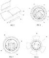
- Fig. 1 shows an eccentric movable vane pump with four annular groove shaped slides 45 being disposed at intervals on a second rotor 4, including: a first rotor 2 (see Fig. 4 ), four movable vanes 21 (see Fig. 2 ), and the second rotor 4.
- the second rotor 4 is eccentrically disposed with the first rotor 2.
- the second rotor 4 is coaxially disposed with a cylinder body 1.
- the first rotor 2 or the second rotor 4 is disposed on a main shaft.
- a lower portion of an outer end 23 of each movable vane 21 is in close proximity to an inner wall of the cylinder body 1; an upper portion of the outer end 23 of the movable vane 21 is provided with a push rod 26; and the push rod 26 slides in a corresponding slide 45 on the second rotor 4.
- a clearance 27 for the second rotor 4 remains between the push rod 26 and the movable vane 21.
- the outer end 23 of the movable vane corresponding to the slide 45 may be provided with an elastic device, such as a spring and an elastic sheet, so as to reduce impact and vibration caused by movement of the movable vane in the slide 45.
- the main shaft can operate in a clockwise rotation as well as in a counterclockwise rotation, and can be applicable to a pressure pump as well as a power pump.
- the cylinder body 1 is provided with a fluid inlet passage 61 and a fluid outlet passage 62.
- the push rods 26 are of flat-plate-shaped structures. With the operation of the rotor, the push rods 26 radially move in the slides 45 in a reciprocating manner.
- movable vanes 21 are disposed in an eccentric movable vane pump (see Fig. 5 ). Inner ends 22 of the movable vanes 21 are respectively coupled to four rotor shaft holes 24 circumferentially and uniformly distributed on an outer wall of a first rotor 2.
- Four different second rotors 4 are axially concentrically arranged.
- the first rotor 2 is secured to a main shaft 11.
- Outer ends 23 of the movable vanes 21 are further provided with shaft pins 231, and the shaft pins 231 are coupled to rotor shaft holes 44 of the second rotors 4.
- Each movable vane 21 is further provided with a clearance 232 for other second rotors 4 that are not coupled to the movable vane 21.
- the eccentric movable vane pump When the eccentric movable vane pump operates, parts of the outer ends 23 of the movable vanes 21 that do not correspond to the second rotors 4 are in close proximity to an inner wall of a cylinder body 1.
- the first rotor 2 is fixedly connected to the main shaft 11.
- the eccentric movable vane pump can operate clockwise or counterclockwise.
- the cylinder body is provided with a fluid inlet 61 and a fluid outlet 62.
- an eccentric movable vane pump is provided with four movable vanes 21 and four second rotors 4.
- Each second rotor 4 is axially concentrically disposed on an eccentric shaft 14 through a bearing.
- the eccentric shaft 14 is eccentrically disposed with a first rotor 2 and is fixedly disposed on the cylinder body 1.
- the first rotor 2 is coaxially disposed on the cylinder body 1 through a bearing.
- the first rotor 2 is secured to a main shaft 11.
- Inner ends 22 of the movable vanes 21 are respectively coupled to rotor shaft holes 24 circumferentially and uniformly distributed on the first rotor 2.
- Outer ends 23 of the movable vanes 21 are respectively coupled to rotor shaft holes 44 on the four second rotors 4.
- a wall surface of the first rotor 2 corresponding to a space between adjacent movable vanes 21 is provided with a fluid passage 60.
- the inner end 22 of each movable vane 21 is provided with a shaft pin 231 and a clearance 232 (see Fig. 5 ).
- an oil valve device is disposed at a corresponding position on the cylinder body 1 or a position corresponding to the first rotor 2, and an oil-gas mixture is ignited when the space is compressed to a certain extent, which is applicable to an internal combustion engine.
- Two identical eccentric movable vane pumps of the present invention are disposed on a same main shaft by 180° with respect to each other, so as to eliminate eccentric vibration.
- a plurality of eccentric movable vane pumps can serve as a multi-stage compression or expansion eccentric movable vane pump, and can function as a gas turbine by means of combination.
- skirts are circumferentially and uniformly distributed on a first rotor 2.
- the skirts are respectively provided with rotor shaft holes 24 that are respectively coupled to inner ends 22 of movable vanes 21.
- Outer ends 23 of the movable vanes 21 are respectively coupled to rotor shaft holes 44 disposed on a second rotor 4.
- Four tunnels 25 are further respectively provided on an outer wall of the first rotor 2.
- Two end faces of a cylinder body 1 are provided with two cylinder body covers 15.
- the cylinder body covers 15 are provided with composite gas passages 53.
- Each composite gas passage 53 is formed by a fluid inlet 61 and a fluid outlet 62.
- the composite gas passages 53 penetrate through the cylinder body 1.
- the composite gas passages 53 are located at an overlapping area of a space between two adjacent movable vanes 21 and the cylinder body 1, and the cylinder body covers 15 when the space gradually reaches a maximum volume and gradually decreases from the maximum volume.
- spark plugs disposed in the tunnels 25 are ignited to fire a compressed oil-gas mixture, a high-temperature high-pressure gas being generated gradually expands to the composite gas passages 53, fresh air enters the cylinder body 1 from one of the composite gas passages 53, and the high-temperature gas in the cylinder body is discharged from the other one of the composite gas passages 53.
- the eccentric movable vane pump is a two-stroke engine, and has an effect of high compression (ignition)-high expansion-efficient gas replacement.
- a structure of Fig. 7 is substantially the same as the structure of Fig. 6 , except that a plurality of gas passages 60 are disposed on a first rotor 2, and opening and closing of the gas passages 60 are controlled by a valve mechanism 55.
- the valve mechanism 55 opens the gas passages 60.
- the valve mechanism 55 may be electrically controlled, or formed by a pulley and a camshaft.
- the eccentric movable vane pump completes a power cycle with four strokes, and is a four-stroke engine.
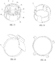
- each of four second rotors 4 is separately provided with a fixed vane 20.
- a displacement space 56 between adjacent fixed vanes 20 undergoes a periodic change, so as to form a displacement pump by components such as the fixed vanes 20 and the pump body.
- the displacement pump is also applicable to fields such as internal combustion engines and compressors.
- Fig. 9 includes two movable vanes 21 and two corresponding second rotors 4. Each second rotor 4 is connected to two fixed vanes 20 through a fixed-transmission-ratio mechanism. Each fixed vane is provided with two symmetrical blades. A gear mechanism is set as the fixed-transmission-ratio mechanism, and a gear ratio is 1/2. During two revolutions of the second rotors, the fixed vanes 20 are rotated through one revolution. In this way, a rotation speed of each fixed vane 20 undergoes two periodic changes of quick-slow conversion during one revolution of the fixed vane 20, which corresponds to that the fixed vane 20 undergoes two compression processes and two expansion processes during one revolution of the fixed vane 20 in the pump. Four strokes of a four-stroke engine are completed during one revolution of the fixed vanes 20. As a four-stroke internal combustion engine, this embodiment can be applied as a common pump without a valve structure.
- Fig. 10 shows two structural forms of a rotor, one of which is a composite structure of a complete annular rotor and an arc-shaped rotor, and the other of which is that an arc-shaped rotor is secured to an end face of a connecting shaft 33 for connecting the arc-shaped rotor and a movable vane 21.
- Fig. 11 is a schematic diagram of a water pump with four arc-shaped slider rotors 34 as second rotors 4. An inner arc surface and an outer arc surface of each arc-shaped slider rotor 34 slide in a slide disposed on a cylinder body 1.
- a fluid passage 5 on the cylinder body 1 is set according to a specific position of a compressed space between adjacent vanes 21 and the cylinder body.
- the fluid passage of the cylinder body 1 is in communication with a cylinder wall through a flange joint, and an inner wall surface of the cylinder body 1 further has a clearance passage for a fluid.
- a rotor shaft hole 44 disposed on a second rotor 4 is replaced by the connecting shaft 33, that is, the design of using a shaft to replace a shaft hole also falls within the protection scope of the present invention.
- Fig. 12 shows a plurality of forms of a second rotor 4, one of which is that the second rotor 4 is fixedly disposed in a plane of an end of the connecting shaft 33 for connecting the second rotor 4 and a movable vane 21, and a plurality of second rotors 4 are sequentially disposed radially concentrically in planes of other parts of the connecting shaft 33. In this manner, a relatively low cost and a relatively good sealing effect can be achieved.
- shaft holes 44 disposed on skirts of the second rotors 4 are coupled to movable vanes 21, and inner wall surfaces 31 of the skirts are of heights the same as heights of the movable vanes 21 and overlap outer wall surfaces of the second rotors 4.
- Such a structure of skirts of the rotors can achieve a higher connection strength and a better sealing effect between the rotors and the movable vanes.
- Fig. 15 also discloses that a design of replacing a shaft hole disposed on a rotor with a shaft falls within the protection scope of the present invention, and multiple forms of a connection between a rotor and a movable vane are not described one by one.
- a plurality of spaced controlled valves are axially distributed at a fluid passage of the cylinder body 1, so as to increase an operation pressure range of the eccentric movable vane pump of the present invention.
- Fig. 13 is a schematic diagram of an eccentric movable vane pump
- Fig. 14 is a diagram of a specific structure of a first rotor 2 in Fig. 13 .
- An upper end and a lower end of the first rotor 2 may be provided with first rotor covers that rotate with the first rotor 2 and are flush with an upper end face and a lower end face of a movable vane 21, or are provided with cylinder body covers that are flush with an upper end face and a lower end face of a movable vane 21 and are secured to the cylinder body 1.
- an eccentric shaft 14 is secured to the cylinder body 1 through a support shaft 114 coaxial with the first rotor 2, and the cylinder body 1 is secured to a frame.
- the eccentric shaft 14 is disposed coaxially second rotors 4 and eccentrically with the first rotor 2.
- the first rotor 2 is connected to a power input/output shaft, and is mounted on the frame by means of a bearing, or is mounted on the support shaft 114 by means of a bearing.
- the four second rotors 4 are sequentially mounted coaxially and serially on the eccentric shaft 14 by means of four bearings 4.
- Outer circular wall surfaces of the four second rotors 4 are respectively provided with shafts/shaft holes coupled to movable vanes 21, and the shafts/shaft holes are respectively rotatably connected to one ends of the four movable vanes 21.
- the other ends of the four movable vanes are respectively rotatably connected to shafts/shaft holes uniformly disposed on an inner wall of the first rotor 2.
- a cylinder body fluid inlet 61 and a cylinder body fluid outlet 62 disposed on the cylinder body 1 correspond to a compression area and an expansion area of a displacement space between adjacent movable vanes 21.
- the first rotor 2 and the second rotors 4 rotate clockwise.
- the second rotors 4 are eccentrically disposed with the first rotor 2.
- Fig. 13 for example, two control mechanisms 63 are provided, and when rotating, the two control mechanisms 63 respectively adjust widths and positions of the cylinder body fluid inlet 61 and the cylinder body fluid outlet 62, so as to adjust the amount of a working fluid during one revolution of the eccentric movable vane pump.
- a rotatable connection manner between the movable vanes 21 and the first rotor 2 and between the movable vanes 21 and the second rotors 4 may be a shaft hole-type rigid connection manner, or may be a flexible connection manner by using a soft material or an elastic material for connection portions.
- Fig. 15 shows that an arc-shaped skirt is further provided on a second rotor 4, and the arc-shaped skirt can improve the connection strength and sealing effect between the second rotor 4 and a corresponding movable vane 21.
- Fig. 16 is a schematic plan view of cooperation of four second rotors 4 with arc-shaped skirts in FIG. 15 .
- Upper and lower end faces of the arc-shaped skirts are flush with cylinder body covers or first rotor covers, such that a working fluid cannot flow into end face contact clearances generated from serial connection of a plurality of second rotors 4, and bearings and a coolant or lubricating oil inside the second rotors 4 can be protected.
- adjacent arc-shaped skirts are nested with each other, so as to separate all the outer spaces from inner spaces, and when an elastic sealing body is used, a good sealing effect can be achieved.
- Fig. 17 is a three-dimensional schematic structural diagram showing that an upper wall surface and a lower wall surface of a first rotor 2 are respectively provided with a rotor fluid outlet 59 and a rotor fluid inlet 58.
- An isolation ring 17 is further disposed between the rotor fluid outlet 59 and the rotor fluid inlet 58, and the isolation ring 17 is disposed on a cylinder body 1.
- two control mechanisms 63 can respectively adjust widths and positions of a cylinder body fluid inlet 58 and a cylinder body fluid outlet 59, so as to adjust the amount of a working fluid during one revolution of an eccentric movable vane pump.
- the cylinder body fluid inlet 61 and the fluid outlet 62 are respectively disposed at the upper portion and the lower portion of the cylinder body by means of the isolation ring 17, so as to increase travels of a high-pressure area and a low-pressure area, and obtain a better isolation and sealing effect of the fluid inlet and the fluid outlet.
- Fig. 18 shows a combination of two eccentric movable vane pumps, where one eccentric movable vane pump is a pressurization pump for increasing a pressure of a low-pressure fluid entering the eccentric movable vane pump and subsequently discharging the pressurized fluid, and the other eccentric movable vane pump is a depressurization pump for decreasing a pressure of a high-pressure fluid entering the eccentric movable vane pump and subsequently discharging the depressurized fluid.
- one eccentric movable vane pump is a pressurization pump for increasing a pressure of a low-pressure fluid entering the eccentric movable vane pump and subsequently discharging the pressurized fluid
- the other eccentric movable vane pump is a depressurization pump for decreasing a pressure of a high-pressure fluid entering the eccentric movable vane pump and subsequently discharging the depressurized fluid.
- a first rotor and an eccentric shaft of the pressurization pump are fixedly connected, and a first rotor and an eccentric shaft of the depressurization pump are fixedly connected, and the combination of the two pumps may be used as a turbocharger, a gas turbine, an internal combustion engine, and the like.
- the fluid is a liquid
- a volume of the fluid entering the pressurization pump and a volume of the fluid entering the depressurization pump can be adjusted by means of a control mechanism, and the combination of the two pumps may be used as a stepless hydraulic coupler and the like.
- Fig. 19 is similar to Fig. 17 , except that rotatable controlled valves 65 located at a first rotor 2 are disposed on a rotor fluid inlet 58 and a rotor fluid outlet 59.
- the controlled valve 65 on the rotor fluid inlet 58 rotates inward when an inner side of the first rotor 2 is of a negative pressure
- the controlled valve 65 on the rotor fluid outlet 59 rotates outward when the inner side of the first rotor 2 is of a positive pressure.
- the controlled valve on the rotor fluid inlet 58 is controlled by a control mechanism 63 to rotate outward; and when a pressure of the inner side of the first rotor 2 is close to a pressure of a low-pressure end of the depressurization pump, the controlled valve on the rotor fluid outlet 59 is controlled by the control mechanism 63 to rotate inward.
- the controlled valves 65 are controlled by one of a fluid pressure difference, a centrifugal force, a power, a magnetic force, and an elastic force, or a resultant force of at least two of the forgoing forces.
- Fig. 20 is a schematic structural diagram showing that controlled valves 65 are controlled by a control mechanism 63 by means of a cam in the embodiment 5. With this structure, the controlled valves 65 can be controlled by a position control mechanism to rotate.
- Fig 21 is a schematic diagram of the position control mechanism that cooperates with the controlled valves 65. When a curve of a slide of the control mechanism 63 is changed, opening and closing positions of the controlled valves 65 can be changed, so as to adjust an actual volume of a working fluid.
- the controlled valves 65 may be opened and closed by means of radial sliding. Each of the controlled valves 65 may be further provided with an elastic compensation device, such that actual operation of the controlled valve 65 is not affected when wear and tear of a sliding friction part occurs.
- the control mechanism may control the controlled valves 65 by means of an electromagnetic force. In this embodiment, in particular, when a depressurization pump uses the controlled valves 65, leakage losses and seal friction losses of a high-pressure end and a low-pressure end can be substantially reduced, and processing precision of parts is substantially reduced. When a fluid is a gas, squeak and surge can be avoided.
- Fig. 22 is substantially the same as Fig. 13 , and is a schematic structural diagram showing that a cylinder body 1 and cylinder body fluid passages are added.
- Fig. 23 is a schematic structural diagram of assembly of second rotors 4 and movable vanes in Fig. 22 .
- Fig. 24 is a schematic structural diagram of a first rotor 2 and valves 65 with cam followers.
- a cam follower 656 is disposed on each valve 65.
- Four rotor fluid passages 60 are uniformly distributed on the first rotor 2.
- One valve 65 is disposed corresponding to each rotor fluid passage 60.
- the valve 65 is controlled by a cam mechanism 655.
- the cam mechanism 655 is formed by a cam follower 656 and a cam 657, and the cam follower 656 opens or closes the valve 65 with a change of an acting face of the cam 657.
- Fig. 25 is a schematic structural diagram of a track mechanism 101.
- the track mechanism 101 has two tracks with different diameters.
- the two tracks with different diameters are connected by means of a cross track 102 to form a closed loop, that is, a rotor or a slider that works with the track mechanism 101 and controls the opening or closing of a valve 65 is located at one track, and can only enter the other track after passing the cross track 102, which corresponds to an action of changing from an opened state to a closed state of the valve 65 or an action of changing from a closed state to an opened state of the valve 65.
- the cross track 102 may be further provided with a mechanism such as a guide groove, a guide path, or an elastic mechanism, so as to assist to limit a track changing action of the slider or the rotor on the track mechanism 101.
- a mechanism such as a guide groove, a guide path, or an elastic mechanism, so as to assist to limit a track changing action of the slider or the rotor on the track mechanism 101.
- the state corresponds to an opened state of the controlled valve 65
- the state corresponds to a closed state of the valve 65
- the state corresponds to a state of changing from an opened state to a closed state or changing from a closed state to an opened state.
- This embodiment is used as a four-stroke engine.
- the two tracks in the track mechanism 101 enable the opened state and the closed state of the controlled valve 65 to correspond to a compression state and an expansion state of the engine.
- the track mechanism 101 is provided with a rotation mechanism 111.
- the rotation mechanism 111 can rotate the track mechanism 101.
- a relative positional relationship among the track mechanism 101, the first rotor 2, and each of the valves 65 changes, which corresponds to changes of a starting/ending position of an opened state and a starting/ending position of a closed state of the valve 65, so as to change a gas intake amount, a compression ratio, and an expansion ratio.
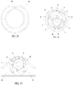
- Fig. 26 is a schematic structural diagram of a variable-displacement pump added with a control shaft 75.
- an isolation zone 18 isolates a high-pressure area from a low-pressure area of a cylinder body.
- a clearance area 19 is in communication with a corresponding one of a cylinder body fluid inlet 61 or a cylinder body fluid outlet 62.
- the control shaft 75 is eccentrically disposed with both an eccentric shaft 14 and a first rotor 2, rotatably disposed on the cylinder body 1, and is controlled by a control mechanism to rotate.
- the control mechanism may be a stepper motor control mechanism, a control mechanism of a stepper motor, a lead screw and a connecting rod, or other control mechanisms.
- a distance between axes of the eccentric shaft 14 and the first rotor 2 changes with the rotation of the control shaft 75, and consequently, a difference between a maximum space 25 and a minimum space 26 of a space between adjacent movable vanes changes, so as to change an actual volume of a working fluid during one revolution of the variable-displacement pump.
- an adjustment mechanism of the control shaft 75 may be further added, so as to change a position of the control shaft 75, thereby achieving a better operation effect of an eccentric movable vane pump.
- This embodiment can be used as a stepless hydraulic coupler or a stepless hydraulic transmission.
- Fig. 27 is a schematic structural diagram of an eccentric movable vane pump of the present invention as an impeller.
- a first rotor 2 is disposed on a cylinder body 1; second rotors 4 are disposed on an eccentric shaft 14; movable vanes 21, the first rotor, and the second rotors rotate clockwise;
- a fluid inlet 61 is located at an area of the cylinder body 1 corresponding to a state that a space between adjacent movable vanes 21 is in an expanded state and a volume of the space is relatively large;
- a corresponding fluid outlet 62 is located at an area of the cylinder body 1 corresponding to a state that a space between adjacent movable vanes 21 is in a compressed state and a volume of the space is relatively large.
- a fluid passage 60 of the first rotor 2 is maximized, the first rotor 2 includes an upper circular sheet-shaped structure and a lower circular sheet-shaped structure, and no annular structure body is disposed at the middle of the first rotor 2.
- the impeller when the impeller is in an operating state, a degree of coincidence between a flow direction of a fluid and a direction of action of the movable vanes 21 that generate thrust is high, and the fluid encounters an extremely small head resistance in a process of flowing through the impeller, such that an impeller with a high efficiency and multiple operation conditions is obtained.
- the impeller can be applied to facilities such as an aircraft, a marine vessel, and a submarine.
- the structure of this embodiment may be used as a wind engine or a hydraulic engine.
Landscapes
- Engineering & Computer Science (AREA)
- Mechanical Engineering (AREA)
- General Engineering & Computer Science (AREA)
- Physics & Mathematics (AREA)
- Fluid Mechanics (AREA)
- Aviation & Aerospace Engineering (AREA)
- Chemical & Material Sciences (AREA)
- Combustion & Propulsion (AREA)
- Ocean & Marine Engineering (AREA)
- Rotary Pumps (AREA)
- Details And Applications Of Rotary Liquid Pumps (AREA)
- Applications Or Details Of Rotary Compressors (AREA)
Applications Claiming Priority (5)
| Application Number | Priority Date | Filing Date | Title |
|---|---|---|---|
| CN201420169067.3U CN203796560U (zh) | 2014-03-10 | 2014-04-09 | 偏心活动叶片泵 |
| CN201420233783.3U CN204082533U (zh) | 2014-05-08 | 2014-05-08 | 偏心活动叶片泵 |
| CN201420605560 | 2014-10-18 | ||
| CN201420773442 | 2014-12-08 | ||
| PCT/CN2015/075934 WO2015154645A1 (zh) | 2014-04-09 | 2015-04-05 | 偏心活动叶片泵 |
Publications (2)
| Publication Number | Publication Date |
|---|---|
| EP3144532A1 true EP3144532A1 (de) | 2017-03-22 |
| EP3144532A4 EP3144532A4 (de) | 2018-03-07 |
Family
ID=54287324
Family Applications (1)
| Application Number | Title | Priority Date | Filing Date |
|---|---|---|---|
| EP15776220.4A Withdrawn EP3144532A4 (de) | 2014-04-09 | 2015-04-05 | Exzentrische bewegliche flügelzellenpumpe |
Country Status (8)
| Country | Link |
|---|---|
| US (1) | US20170030352A1 (de) |
| EP (1) | EP3144532A4 (de) |
| JP (1) | JP6408027B2 (de) |
| KR (1) | KR20160143785A (de) |
| BR (1) | BR112016023581A2 (de) |
| CA (1) | CA2944804A1 (de) |
| EA (1) | EA201692033A1 (de) |
| WO (1) | WO2015154645A1 (de) |
Families Citing this family (8)
| Publication number | Priority date | Publication date | Assignee | Title |
|---|---|---|---|---|
| DE102017222698A1 (de) * | 2017-12-14 | 2019-06-19 | Zf Friedrichshafen Ag | Flügelzellenpumpe |
| CN109322825A (zh) * | 2018-11-22 | 2019-02-12 | 白晓瑞 | 一种复合转子压缩机 |
| US11505327B2 (en) | 2020-03-16 | 2022-11-22 | Goodrich Corporation | Gas delivery augmenter with pump mechanism |
| KR102202708B1 (ko) | 2020-04-14 | 2021-01-14 | 안용준 | 가변임펠러를 이용한 로터리 펌프 |
| CN111377059B (zh) * | 2020-05-19 | 2022-11-04 | 重庆宇矛航空科技有限公司 | 高提升力无翼飞行器动力系统 |
| TR202106685A2 (tr) * | 2021-04-15 | 2021-05-21 | Alp Arge Otomotiv Tasarim San Ve Tic A S | Yeni̇ bi̇r rotorlu fren vakum pompasi |
| CN113323876B (zh) * | 2021-07-05 | 2022-03-08 | 珠海格力电器股份有限公司 | 一种压缩机的吸气增压结构和压缩机 |
| CN117329127B (zh) * | 2023-12-01 | 2024-02-02 | 成都理工大学 | 一种滑片式与离心式复合的压缩机械 |
Family Cites Families (16)
| Publication number | Priority date | Publication date | Assignee | Title |
|---|---|---|---|---|
| FR479354A (fr) * | 1915-07-22 | 1916-03-17 | Franey Shore Company | Pompe rotative |
| US1769079A (en) * | 1929-04-29 | 1930-07-01 | Jay M Smith | Rotary impeller mechanism |
| US1886206A (en) * | 1929-08-30 | 1932-11-01 | Firm Climax Motorenwerke Und S | Rotary blower |
| US2139856A (en) * | 1936-02-27 | 1938-12-13 | Savage Leonard George | Pump, engine, and the like |
| US2464208A (en) * | 1945-10-31 | 1949-03-15 | Calvin M Bolster | Expansible chamber fluid motor or pump |
| DE875983C (de) * | 1948-12-24 | 1953-05-07 | Hugues Schellenberg | Rotationskompressor mit schwenkbaren Schaufeln |
| DE1403748C3 (de) * | 1961-10-13 | 1974-08-29 | Breinlich, Richard, Dr., 7120 Bietigheim | Hydraulische Radialkolbenmaschine |
| DE1453724A1 (de) * | 1963-08-14 | 1969-05-08 | Breinlich Dr Richard | Kolbenschuhe und Kolbenschuhfuehrungen in Radialkolbenmaschinen |
| FR1549241A (de) * | 1967-07-28 | 1968-12-13 | ||
| JPS608401U (ja) * | 1983-06-28 | 1985-01-21 | 株式会社島津製作所 | ロ−タリ式流体機械 |
| JP3441100B2 (ja) * | 1992-12-28 | 2003-08-25 | ユニシア ジェーケーシー ステアリングシステム株式会社 | 可変容量形ポンプ |
| JP2932236B2 (ja) * | 1994-02-28 | 1999-08-09 | 自動車機器株式会社 | 可変容量形ポンプ |
| JP2000087877A (ja) * | 1998-09-10 | 2000-03-28 | Bosch Braking Systems Co Ltd | 可変容量形ポンプ |
| JP3861594B2 (ja) * | 2000-12-15 | 2006-12-20 | ユニシア ジェーケーシー ステアリングシステム株式会社 | オイルポンプ |
| US7632084B2 (en) * | 2004-08-02 | 2009-12-15 | Panasonic Corporation | Oilless rotary vane pump having open ends of vane grooves being inclined rearward in the rotation direction |
| CN102536805A (zh) * | 2011-12-31 | 2012-07-04 | 张洪领 | 一种叶片泵 |
-
2015
- 2015-04-05 EA EA201692033A patent/EA201692033A1/ru unknown
- 2015-04-05 JP JP2016560961A patent/JP6408027B2/ja not_active Expired - Fee Related
- 2015-04-05 US US15/301,396 patent/US20170030352A1/en not_active Abandoned
- 2015-04-05 BR BR112016023581A patent/BR112016023581A2/pt not_active IP Right Cessation
- 2015-04-05 CA CA2944804A patent/CA2944804A1/en not_active Abandoned
- 2015-04-05 EP EP15776220.4A patent/EP3144532A4/de not_active Withdrawn
- 2015-04-05 WO PCT/CN2015/075934 patent/WO2015154645A1/zh active Application Filing
- 2015-04-05 KR KR1020167031235A patent/KR20160143785A/ko not_active Application Discontinuation
Also Published As
| Publication number | Publication date |
|---|---|
| JP6408027B2 (ja) | 2018-10-17 |
| EP3144532A4 (de) | 2018-03-07 |
| US20170030352A1 (en) | 2017-02-02 |
| EA201692033A1 (ru) | 2017-06-30 |
| KR20160143785A (ko) | 2016-12-14 |
| JP2017520708A (ja) | 2017-07-27 |
| WO2015154645A1 (zh) | 2015-10-15 |
| CA2944804A1 (en) | 2015-10-15 |
| BR112016023581A2 (pt) | 2017-12-26 |
Similar Documents
| Publication | Publication Date | Title |
|---|---|---|
| EP3144532A1 (de) | Exzentrische bewegliche flügelzellenpumpe | |
| RU2651000C2 (ru) | Устройство для машины смещающего типа, управляющая зубчатая передача для устройства и использование управляющей зубчатой передачи | |
| EP2581552B1 (de) | Spiraster-fluidmotor und kompressor oder pumpe dafür | |
| EP1686263B1 (de) | Radialkolbenpumpe mit variabler Verdrängung | |
| CN203796560U (zh) | 偏心活动叶片泵 | |
| US7314035B2 (en) | Rotary vane engine and thermodynamic cycle | |
| RU183285U1 (ru) | Пластинчатый двигатель | |
| WO2021088135A1 (zh) | 具有泽仑圆形状的腔体、流体工作装置以及发动机 | |
| CN108678810B (zh) | 平面回转式膨胀机 | |
| RU200122U1 (ru) | Многопластинчатый двигатель | |
| RU186583U1 (ru) | Роторный двигатель | |
| CN103498727A (zh) | 叶片式发动机 | |
| CN111287972B (zh) | 叶旋压缩机 | |
| CN104454020B (zh) | 具有转轮旋叶回旋机构的流体动力机械 | |
| CN203515794U (zh) | 叶片式发动机 | |
| RU138105U1 (ru) | Роторное устройство с шибером при внешнем цилиндре ротора | |
| CN216406910U (zh) | 变容式螺旋盘转子流体机械装置 | |
| US11873813B2 (en) | Suction/compression rotating mechanism, rotary compressor and rotary engine | |
| CN1225594C (zh) | 环流喷气式转子热机 | |
| WO2015058635A1 (zh) | 一种能量转换装置 | |
| CN202597086U (zh) | 转子流体机械变容机构 | |
| CN204082533U (zh) | 偏心活动叶片泵 | |
| RU165397U1 (ru) | Роторно-поршневой двигатель | |
| RU2300647C2 (ru) | Роторный двигатель непрерывного сгорания | |
| RU115414U1 (ru) | Роторно-поршневая машина |
Legal Events
| Date | Code | Title | Description |
|---|---|---|---|
| STAA | Information on the status of an ep patent application or granted ep patent |
Free format text: STATUS: THE INTERNATIONAL PUBLICATION HAS BEEN MADE |
|
| PUAI | Public reference made under article 153(3) epc to a published international application that has entered the european phase |
Free format text: ORIGINAL CODE: 0009012 |
|
| STAA | Information on the status of an ep patent application or granted ep patent |
Free format text: STATUS: REQUEST FOR EXAMINATION WAS MADE |
|
| 17P | Request for examination filed |
Effective date: 20161109 |
|
| AK | Designated contracting states |
Kind code of ref document: A1 Designated state(s): AL AT BE BG CH CY CZ DE DK EE ES FI FR GB GR HR HU IE IS IT LI LT LU LV MC MK MT NL NO PL PT RO RS SE SI SK SM TR |
|
| AX | Request for extension of the european patent |
Extension state: BA ME |
|
| DAV | Request for validation of the european patent (deleted) | ||
| DAX | Request for extension of the european patent (deleted) | ||
| A4 | Supplementary search report drawn up and despatched |
Effective date: 20180205 |
|
| RIC1 | Information provided on ipc code assigned before grant |
Ipc: F04C 2/40 20060101AFI20180130BHEP |
|
| STAA | Information on the status of an ep patent application or granted ep patent |
Free format text: STATUS: THE APPLICATION IS DEEMED TO BE WITHDRAWN |
|
| 18D | Application deemed to be withdrawn |
Effective date: 20180905 |