US11873813B2 - Suction/compression rotating mechanism, rotary compressor and rotary engine - Google Patents
Suction/compression rotating mechanism, rotary compressor and rotary engine Download PDFInfo
- Publication number
- US11873813B2 US11873813B2 US17/286,297 US201917286297A US11873813B2 US 11873813 B2 US11873813 B2 US 11873813B2 US 201917286297 A US201917286297 A US 201917286297A US 11873813 B2 US11873813 B2 US 11873813B2
- Authority
- US
- United States
- Prior art keywords
- pistons
- compression
- rotary
- cylinders
- piston
- Prior art date
- Legal status (The legal status is an assumption and is not a legal conclusion. Google has not performed a legal analysis and makes no representation as to the accuracy of the status listed.)
- Active, expires
Links
- 230000006835 compression Effects 0.000 title claims abstract description 55
- 238000007906 compression Methods 0.000 title claims abstract description 55
- 230000007246 mechanism Effects 0.000 title claims abstract description 31
- 239000000446 fuel Substances 0.000 claims abstract description 9
- 238000007789 sealing Methods 0.000 claims description 25
- 238000002485 combustion reaction Methods 0.000 claims description 10
- 239000000203 mixture Substances 0.000 claims description 3
- 239000002737 fuel gas Substances 0.000 claims 1
- 239000007789 gas Substances 0.000 description 31
- 238000000034 method Methods 0.000 description 8
- 238000010586 diagram Methods 0.000 description 5
- 239000003921 oil Substances 0.000 description 5
- 239000000567 combustion gas Substances 0.000 description 3
- 238000004519 manufacturing process Methods 0.000 description 3
- 230000006378 damage Effects 0.000 description 2
- 230000000694 effects Effects 0.000 description 2
- 230000001965 increasing effect Effects 0.000 description 2
- 244000118350 Andrographis paniculata Species 0.000 description 1
- 101000897979 Homo sapiens Putative spermatid-specific linker histone H1-like protein Proteins 0.000 description 1
- 102100021861 Putative spermatid-specific linker histone H1-like protein Human genes 0.000 description 1
- 238000005299 abrasion Methods 0.000 description 1
- 230000000712 assembly Effects 0.000 description 1
- 238000000429 assembly Methods 0.000 description 1
- 238000010276 construction Methods 0.000 description 1
- 230000007423 decrease Effects 0.000 description 1
- 230000003247 decreasing effect Effects 0.000 description 1
- 230000001419 dependent effect Effects 0.000 description 1
- 230000002708 enhancing effect Effects 0.000 description 1
- 238000009434 installation Methods 0.000 description 1
- 239000010687 lubricating oil Substances 0.000 description 1
- 238000012423 maintenance Methods 0.000 description 1
- 239000000463 material Substances 0.000 description 1
- 239000002184 metal Substances 0.000 description 1
- 239000007787 solid Substances 0.000 description 1
Images


Classifications
-
- F—MECHANICAL ENGINEERING; LIGHTING; HEATING; WEAPONS; BLASTING
- F04—POSITIVE - DISPLACEMENT MACHINES FOR LIQUIDS; PUMPS FOR LIQUIDS OR ELASTIC FLUIDS
- F04C—ROTARY-PISTON, OR OSCILLATING-PISTON, POSITIVE-DISPLACEMENT MACHINES FOR LIQUIDS; ROTARY-PISTON, OR OSCILLATING-PISTON, POSITIVE-DISPLACEMENT PUMPS
- F04C18/00—Rotary-piston pumps specially adapted for elastic fluids
- F04C18/08—Rotary-piston pumps specially adapted for elastic fluids of intermeshing-engagement type, i.e. with engagement of co-operating members similar to that of toothed gearing
- F04C18/12—Rotary-piston pumps specially adapted for elastic fluids of intermeshing-engagement type, i.e. with engagement of co-operating members similar to that of toothed gearing of other than internal-axis type
- F04C18/123—Rotary-piston pumps specially adapted for elastic fluids of intermeshing-engagement type, i.e. with engagement of co-operating members similar to that of toothed gearing of other than internal-axis type with radially or approximately radially from the rotor body extending tooth-like elements, co-operating with recesses in the other rotor, e.g. one tooth
-
- F—MECHANICAL ENGINEERING; LIGHTING; HEATING; WEAPONS; BLASTING
- F04—POSITIVE - DISPLACEMENT MACHINES FOR LIQUIDS; PUMPS FOR LIQUIDS OR ELASTIC FLUIDS
- F04C—ROTARY-PISTON, OR OSCILLATING-PISTON, POSITIVE-DISPLACEMENT MACHINES FOR LIQUIDS; ROTARY-PISTON, OR OSCILLATING-PISTON, POSITIVE-DISPLACEMENT PUMPS
- F04C18/00—Rotary-piston pumps specially adapted for elastic fluids
- F04C18/08—Rotary-piston pumps specially adapted for elastic fluids of intermeshing-engagement type, i.e. with engagement of co-operating members similar to that of toothed gearing
- F04C18/12—Rotary-piston pumps specially adapted for elastic fluids of intermeshing-engagement type, i.e. with engagement of co-operating members similar to that of toothed gearing of other than internal-axis type
- F04C18/14—Rotary-piston pumps specially adapted for elastic fluids of intermeshing-engagement type, i.e. with engagement of co-operating members similar to that of toothed gearing of other than internal-axis type with toothed rotary pistons
- F04C18/18—Rotary-piston pumps specially adapted for elastic fluids of intermeshing-engagement type, i.e. with engagement of co-operating members similar to that of toothed gearing of other than internal-axis type with toothed rotary pistons with similar tooth forms
-
- F—MECHANICAL ENGINEERING; LIGHTING; HEATING; WEAPONS; BLASTING
- F01—MACHINES OR ENGINES IN GENERAL; ENGINE PLANTS IN GENERAL; STEAM ENGINES
- F01C—ROTARY-PISTON OR OSCILLATING-PISTON MACHINES OR ENGINES
- F01C1/00—Rotary-piston machines or engines
- F01C1/08—Rotary-piston machines or engines of intermeshing engagement type, i.e. with engagement of co- operating members similar to that of toothed gearing
- F01C1/082—Details specially related to intermeshing engagement type machines or engines
- F01C1/084—Toothed wheels
-
- F—MECHANICAL ENGINEERING; LIGHTING; HEATING; WEAPONS; BLASTING
- F01—MACHINES OR ENGINES IN GENERAL; ENGINE PLANTS IN GENERAL; STEAM ENGINES
- F01C—ROTARY-PISTON OR OSCILLATING-PISTON MACHINES OR ENGINES
- F01C1/00—Rotary-piston machines or engines
- F01C1/08—Rotary-piston machines or engines of intermeshing engagement type, i.e. with engagement of co- operating members similar to that of toothed gearing
- F01C1/12—Rotary-piston machines or engines of intermeshing engagement type, i.e. with engagement of co- operating members similar to that of toothed gearing of other than internal-axis type
- F01C1/123—Rotary-piston machines or engines of intermeshing engagement type, i.e. with engagement of co- operating members similar to that of toothed gearing of other than internal-axis type with tooth-like elements, extending generally radially from the rotor body cooperating with recesses in the other rotor, e.g. one tooth
-
- F—MECHANICAL ENGINEERING; LIGHTING; HEATING; WEAPONS; BLASTING
- F04—POSITIVE - DISPLACEMENT MACHINES FOR LIQUIDS; PUMPS FOR LIQUIDS OR ELASTIC FLUIDS
- F04C—ROTARY-PISTON, OR OSCILLATING-PISTON, POSITIVE-DISPLACEMENT MACHINES FOR LIQUIDS; ROTARY-PISTON, OR OSCILLATING-PISTON, POSITIVE-DISPLACEMENT PUMPS
- F04C18/00—Rotary-piston pumps specially adapted for elastic fluids
- F04C18/08—Rotary-piston pumps specially adapted for elastic fluids of intermeshing-engagement type, i.e. with engagement of co-operating members similar to that of toothed gearing
- F04C18/082—Details specially related to intermeshing engagement type pumps
- F04C18/084—Toothed wheels
-
- F—MECHANICAL ENGINEERING; LIGHTING; HEATING; WEAPONS; BLASTING
- F04—POSITIVE - DISPLACEMENT MACHINES FOR LIQUIDS; PUMPS FOR LIQUIDS OR ELASTIC FLUIDS
- F04C—ROTARY-PISTON, OR OSCILLATING-PISTON, POSITIVE-DISPLACEMENT MACHINES FOR LIQUIDS; ROTARY-PISTON, OR OSCILLATING-PISTON, POSITIVE-DISPLACEMENT PUMPS
- F04C18/00—Rotary-piston pumps specially adapted for elastic fluids
- F04C18/08—Rotary-piston pumps specially adapted for elastic fluids of intermeshing-engagement type, i.e. with engagement of co-operating members similar to that of toothed gearing
- F04C18/12—Rotary-piston pumps specially adapted for elastic fluids of intermeshing-engagement type, i.e. with engagement of co-operating members similar to that of toothed gearing of other than internal-axis type
- F04C18/14—Rotary-piston pumps specially adapted for elastic fluids of intermeshing-engagement type, i.e. with engagement of co-operating members similar to that of toothed gearing of other than internal-axis type with toothed rotary pistons
- F04C18/16—Rotary-piston pumps specially adapted for elastic fluids of intermeshing-engagement type, i.e. with engagement of co-operating members similar to that of toothed gearing of other than internal-axis type with toothed rotary pistons with helical teeth, e.g. chevron-shaped, screw type
-
- F—MECHANICAL ENGINEERING; LIGHTING; HEATING; WEAPONS; BLASTING
- F04—POSITIVE - DISPLACEMENT MACHINES FOR LIQUIDS; PUMPS FOR LIQUIDS OR ELASTIC FLUIDS
- F04C—ROTARY-PISTON, OR OSCILLATING-PISTON, POSITIVE-DISPLACEMENT MACHINES FOR LIQUIDS; ROTARY-PISTON, OR OSCILLATING-PISTON, POSITIVE-DISPLACEMENT PUMPS
- F04C2/00—Rotary-piston machines or pumps
- F04C2/08—Rotary-piston machines or pumps of intermeshing-engagement type, i.e. with engagement of co-operating members similar to that of toothed gearing
- F04C2/12—Rotary-piston machines or pumps of intermeshing-engagement type, i.e. with engagement of co-operating members similar to that of toothed gearing of other than internal-axis type
- F04C2/14—Rotary-piston machines or pumps of intermeshing-engagement type, i.e. with engagement of co-operating members similar to that of toothed gearing of other than internal-axis type with toothed rotary pistons
- F04C2/16—Rotary-piston machines or pumps of intermeshing-engagement type, i.e. with engagement of co-operating members similar to that of toothed gearing of other than internal-axis type with toothed rotary pistons with helical teeth, e.g. chevron-shaped, screw type
-
- F—MECHANICAL ENGINEERING; LIGHTING; HEATING; WEAPONS; BLASTING
- F04—POSITIVE - DISPLACEMENT MACHINES FOR LIQUIDS; PUMPS FOR LIQUIDS OR ELASTIC FLUIDS
- F04C—ROTARY-PISTON, OR OSCILLATING-PISTON, POSITIVE-DISPLACEMENT MACHINES FOR LIQUIDS; ROTARY-PISTON, OR OSCILLATING-PISTON, POSITIVE-DISPLACEMENT PUMPS
- F04C27/00—Sealing arrangements in rotary-piston pumps specially adapted for elastic fluids
- F04C27/005—Axial sealings for working fluid
-
- F—MECHANICAL ENGINEERING; LIGHTING; HEATING; WEAPONS; BLASTING
- F04—POSITIVE - DISPLACEMENT MACHINES FOR LIQUIDS; PUMPS FOR LIQUIDS OR ELASTIC FLUIDS
- F04C—ROTARY-PISTON, OR OSCILLATING-PISTON, POSITIVE-DISPLACEMENT MACHINES FOR LIQUIDS; ROTARY-PISTON, OR OSCILLATING-PISTON, POSITIVE-DISPLACEMENT PUMPS
- F04C2240/00—Components
- F04C2240/30—Casings or housings
-
- F—MECHANICAL ENGINEERING; LIGHTING; HEATING; WEAPONS; BLASTING
- F04—POSITIVE - DISPLACEMENT MACHINES FOR LIQUIDS; PUMPS FOR LIQUIDS OR ELASTIC FLUIDS
- F04C—ROTARY-PISTON, OR OSCILLATING-PISTON, POSITIVE-DISPLACEMENT MACHINES FOR LIQUIDS; ROTARY-PISTON, OR OSCILLATING-PISTON, POSITIVE-DISPLACEMENT PUMPS
- F04C2250/00—Geometry
- F04C2250/20—Geometry of the rotor
Definitions
- the present invention relates to highly efficient suction and compression rotating mechanisms, particularly the compression mechanism with piston blocks mounted on two axes and driven by a pair of matching gears in the field of compressors and vacuums or hydraulic system such as oil pump, hydraulic motor, hydraulic gearbox, specifically there is application that uses this mechanism to create one rotary motor with multi compression stages, force-generating stages and continuous fuel burning regime.
- rotary compressors or rotary vacuum have a simpler structure and higher flow than reciprocating types, but return-type compressors have difficulty in keeping its working chambers sealed because it is hard to create the absolute precision and to place the parts that sealed the gap between the rotating core and the chamber wall or amongst the rotating cores together.
- the purpose of this invention is to create a rotary compression mechanism with:
- this invention provides a rotary compression mechanism with rotary lobes (similar to air blowers), but has special structures to increase the tightness.
- the new rotary lobe structure in this invention provides a close contact between curved surfaces with the same radius, which is a “surface-to-surface” contact with much better tightness than “line” contact.
- contact here is a symbolic representation, because in fact it is necessary to avoid the actual contact between the rotating lobes or between the rotating lobes with the compression chamber to eliminate friction during working, which can cause destruction of compressor parts, further creating space for thermal expansion of compressor parts during working process.
- the “surface-to-surface” contact in the sealing positions facilitates the installation of sealing parts at all gaps between the rotating core and the pump chamber or among the rotating parts. Meanwhile, the profile of the rotating core do not need to be fabricated accurately while still not affecting the tightness of the pump chamber.
- this invention also provides a special profile for the top face of the piston and the bearing plates. Both have the same basic profile and these profiles are changed to suit their different working requirements and will be discussed later.
- This invention also refers to rotary engines with a similar fuel combustion and force-generation expansion mode to gas turbines based on a rotary compression structure.
- This engine cycle is similar to the gas turbine cycle, which is the the brayton cycle.
- the only difference with gas turbines is the operation of the gas in this place in the closed space, while the operation of the gas in the gas turbine is open space.
- the engine operates in a such mode that the intake air pressure is loaded by the pressure in the combustion chamber is much higher than the intake pressure of the automobile cycle engines.
- these rotary motors need more than one compression stage to achieve high load pressure and intake efficiency.
- FIG. 1 A is a perspective drawing showing an overview of the general structure and the main details of the compressor in a separate state;
- FIG. 1 B is a longitudinal section showing details in the working position
- FIG. 2 is a perspective drawing of removable parts that show the comparison of the thickness of pistons and piston plates;
- FIG. 3 is a schematic drawing showing how to create the baseline of piston profile and bearing plates
- FIG. 4 is a schematic drawing showing the piston's boundary and the effects of basic parameters
- FIG. 5 is a schematic drawing showing the edge of the bearing plate and basic parameters
- FIG. 6 is a sectional view showing the locations where sealing bars can be installed
- FIG. 7 is a schematic diagram of the engine principle according to option 1
- FIGS. 8 A- 8 H are schematic drawings showing the engine's operating stages according to option 1;
- FIG. 9 is a schematic drawing showing the engine operation principle according to option 2.
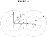
- FIG. 10 is a diagram showing the main profile trajectory of the piston and piston plate.
- FIG. 1 Overview of the general structure and the main details of the compressor:
- the pair of drive gears ( 1 ) is fastened on the two shafts ( 11 ), they drive the pistons to work together accordingly;
- the pump walls ( 2 ) and pump casing ( 4 ) are precisely assembled together thanks to the positioning brackets on the pump wall that forming the pump chamber;
- Ball bearings ( 5 ) are bearings that support axes, which are placed in cylinders ( 3 ) protruding from the pump wall ( 2 );
- the springs ( 6 ) are also arranged in the cylinders ( 3 ) they always push the sealing rings ( 7 ) close to the side of the bearing plates ( 9 ) to seal the gap between the top face of the cylinders ( 3 ) and the side of the bearing plates ( 9 );
- the bearing plates ( 9 ) are fastened on the shaft ( 11 ) and the piston ( 8 );
- the pistons ( 8 ) are symmetrically mounted on both sides of the plates ( 9 ) and symmetrically double through the center of rotation of the axes ( 11 ), which makes the whole block around the axes ( 11 ) balanced completely, while enhancing the bearing capacity of the whole unit during operation;
- the scanning bars ( 12 ) seal the gap between the inside of the piston ( 8 ) and the circumference of the cylinder ( 3 );
- Scanning bars ( 13 ) seal the gap between the concave surface of the cylinder ( 3 ) and the out side of the opposite piston ( 8 );
- the scanning bars ( 14 ) seal the gap between the inside of the pump chamber ( 4 ) and the outside of the piston ( 8 );
- Sealing plates ( 10 ) seal the gap between the side surfaces of the piston ( 8 ) and the pump walls.
- FIG. 2 The image of comparison the thickness of the piston and piston plates
- the thickness of the piston is D
- the thickness of the bearing plate is d.
- FIG. 3 Base curve for creating profile of the piston top and bearing plate
- Point A rotates around point o in a plane parallel to plane B and passes through two points o and p with a oq radius.
- Plane B rotates around point p with the same angular velocity as that of point A but in opposite direction. Point A will draw on the B-plane a curve, which is the base curve to create the profile of the piston top and the bearing plate.
- FIG. 4 Describe how to create piston profile and basic parameters
- piston P 1 is symmetrical with piston P 2 through the axis T 1
- P 3 piston is symmetrical with P 4 piston block through axis T 2 .
- the piston blocks rotate in opposite directions in the space limited by compressor case and cylinders C 1 and C 2 .
- the profile of piston top consists of two curves ab and bc, where the curve ab is part of the base curve abd, which is the curve as mentioned in the previous section.
- the curve bc is the symmetry of the remaining bd part of the base curve through the straight line ef going through the center of rotation T 2 and point b.
- the profile of piston top consists of two curves ab and bc, where the curve ab is part of base curve abd, wick is the curve as mentioned in the previous section.
- the curve bc is the symmetry of the remaining bd part of the base curve through the straight line ef going through the center of rotation T 2 and point b.
- the profile at the other end of the piston is symmetrically aligned to the center of rotation so that the angle is creat by two vetices of the piston and the center of rotation is 90 degrees.
- the angle gkh will be 90 degrees.
- This new compression mechanism has added cylinders C 1 and C 2 , which are mounted on the walls of the compressor chamber, having the center axis coinciding with the center of rotation of the piston blocks, the outer radius of the cylinders respectively with internal radius of piston blocks.
- These cylinders are concave cut by arc mn with radius corresponding to the outer radius of the piston blocks and the center of the arc mn coincides with the center of rotation of the opposite piston blocks.
- the length of cylinder is equal to the width of the piston blocks. This makes the sealing of fully piston blocks a “surface-to-surface” contact and the compressor's tightness significantly increased compared to existing rotary lobe compressors.
- That mounting of symmetrical piston blocks on the bearing plate is for the entire rotary movement of the compressor to be fully balanced, the compressor can operate in high rotation mode, providing high durability and large flow of compressor.
- PV 1 slash section is the volume limited by out side and top side of piston P 1 , P 2 , cylinder and compressor case.
- the slash section PV 2 is a volume that smaller than the limited by the curved surfaces mn on cylinders C 1 , C 2 and top side of pistons P 1 , P 4 at the time they form the closed space during rotation.
- the profile of the piston top are not involved in sealing, ie the piston top of two pistons on the two axes do not need to touch each other, in fact the magnitude of the gap between them during the operation completely selected by the designer.
- the sealing is entirely dependent on the gap between the inside surface of the pump chamber, the piston body surface, the outer surface of the cylinder and the side surface of bearing plate.
- the profile of the piston top only works to optimize the compression ratio, increasing the efficiency of the compressor. This make the construction of the compressor simpler. The accurate when processing the profile of piston top and the profile of the bearing plate and the pair of drive gears that are not as strict as in other rotary lobe compressor.
- FIG. 5 Describe the profile of the bearing plate and the basic parameters.
- the bearing plate is a metal plate with its thickness much smaller than the thickness of the piston, the bearing plate is mounted on the rotating shaft of the compressor in the middle position of the compression chamber, located between the two ends of the cylinders C 1 and C 2 .
- the front edge of the bearing plate is similar in structure to that of the piston head. but there is a much smaller curve bc, the curve bc on profile bearing place top is only the purpose to make “blunt” the sharp edge of the bearing plate.
- the R 3 radius of the bearing plate can be considered approximately as the outer radius R 1 of the bearing plate.
- DV 1 is the volume fraction limited by a profile of the bearing plate, the compressor walls and the compressor case
- DV 2 is the volume limited by two profile of the two bearing plates and the compressor walls when they form a closed space.
- the main task of the bearing plate is to mount the piston blocks with the rotating shaft into a uniform rotating block, the bearing plate also participates in a very small part in compressing the like the rotary lobes of the compressors with the rotary lobe in the form of “line”, however, because the bearing plate's thickness is very small compared to the thickness of the piston blocks, it does not much affect the tightness of the compressor.
- the thickness of the bearing plate is only designed to be durable enough to avoid destruction during the compressor's working process.
- the piston blocks can be fabricated separately and then mounted on the bearing plate or can be monolithic fabricated with the bearing plate.
- the outer radius of the bearing plate is equal to the outer radius of the piston blocks, so the outer radius of whole block is R 1 , which makes the chamber shape of the compressor becoming simple cylindrical, quite similar to the machine chamber of conventional screw air compressors or lobe blowers, manufacturing is simple and nothing special.
- the compression ratio of the compressor is mainly the result of the ratio between PV 1 and PV 2 .
- the ratios of R 1 , R 2 , R 3 and H generate different compressions and compression ratios of compressors, when the designed flow increases, the compression ratio decreases and vice versa.
- R 1 is the outer radius of the piston.
- FIG. 6 The locations where sealing bars can be installed:
- the scanning bars ( 14 ) are placed on the pump case to seal the gap between the outside of the piston and the inner wall of the pump case;
- the scanning bars ( 12 ) are placed on the cylinder (H 1 . 3 ) to seal the gap between the inside of the piston and the outside of the cylinder (H 1 . 3 );
- Sealing plates ( 10 ) mounted on pistons to seal the gap between piston's side and the pump wall (H 1 . 2 );
- the sealing plates ( 7 ) are mounted on the ends of the cylinders to seal the gap between the cylinder's top (H 1 . 3 ) with side surface of bearing plates (H 1 . 9 );
- the scanning bars ( 13 ) are mounted on the cylinders (H 1 . 3 ) to seal the concave surfaces of cylinder (H 1 . 3 ) and the outside of the piston on the opposite side.
- FIG. 7 Diagram of the engine operation principle according to option 1:
- Air passes through the inlet of the primary compressor ( 20 ). After primary air compression is fed into a gas tank ( 22 ) and continues into the secondary compressor ( 21 ). The high pressure air passes through the one-way valve ( 23 ) to the combustion chamber ( 23 ). Here the fuel is sprayed through a nozzle ( 25 ) of high pressure mixed with compressed air and in the combustion chamber ( 24 ). The burning gas is directed into the force-generating stage.
- the rotary gas distribution valve ( 26 ) open the inlet compartments ( 27 ) and closes the cavity at the top of piston, the burning gas passing through into the compartments ( 27 ).
- the rotary gas distribution valve ( 26 ) closes the inlet compartments ( 27 ) and open the cavity at the piston top open through with the compartment ( 27 ) the hot air will expand and generate energy.
- the rotary gas distribution valve ( 26 ) is driven according to the rotation speed of the motor shaft so that the process of air distribution and expansion is smooth.
- the ratio of the cavity ( 27 ) on a piston expansion volume can reach 1:25 or more, thus taking advantage of the expansion energy of combustion gas, enhance the efficiency of the engine.
- Compression stages and the force-generating stages are driven by a pair of gears through two active axes.
- the rotary gas distribution valve ( 26 ) are driven by belt gear pairs ( 29 ) and ( 30 ), which rotate at the same speed with the engine axes.
- the principle diagram here shows that the engine has two sequential compression stages and two parallel force-generating stages, the number of compression or force-generating floors may be more or less depending on the purpose or actual requirements.
- FIGS. 8 A- 8 H Description of the engine operation stages according to option 1:
- FIG. 8 A Rotary valve (RV) is a hollow tube with gate inlets and outlets;
- the belt wheel (N 2 ) is attached to the drive shaft, through the toothed belt or chain to transmits to the belt wheel (N 1 ) as the air valve (RV) rotating with the same speed of the motor shaft;
- the compartments (L) and (R) are also placed alternately in the following order: gate 1 and gate 2 are placed corresponding to the cavity (R), gate 3 and gate 4 are set corresponding to the cavity (L);
- the burning gas under high pressure is passing through the pipe (G 1 ) passing through doors 2 and 3 into the rotary valve (RV);
- the burning gas begins to under high pressure is passing through the pipe (G 1 ) passing through doors 2 and 3 into the rotary valve (RV);
- the burning gas
- FIG. 8 B burning gas from inside the valve (RV) through gate 1 into the cavity (R); The expansion process continues on the left piston chamber; burning gas is still going through gate 2 into the valve (RV).
- FIG. 8 C the expansion of the piston chamber on the left ends; The process of filling high pressure air into the cavity (R) ends.
- FIG. 8 D burning gas from the cavity (R) begins to expand into the right piston chamber.
- FIG. 8 E Burning gas go through door 4 into the rotary valve (RV); Burning gas enters the cavity (L) through gate 3 ; The process of expansion on the right piston chamber is continuing.
- FIG. 8 F Burning gas flows into the rotary valve (RV) through both gates 4 and 1 ; The process of expansion on the right piston chamber ends.
- FIG. 8 G Burning gas continues into the rotary valve (RV) through door 1 ; Burning gas from the cavity (L) is expanding into the left piston chamber; Burning gas go into cavity (R) through gate 2 .
- FIG. 8 H Sealing parts between the left piston and the right piston.
- the piston assemblies at the force-generating floors on the same axis are arranged to rotate evenly around the axis for the purpose of creating a smooth torque for the engine. Therefore the combustion gas mixture from the combustion chamber is always continuously loaded into the rotary valves at all times.
- the air supply valve When the air supply valve is closed, it will allow the expansion air into the piston chamber, so if the volume of these closed chambers is of sufficient size, the engine will be able to maximize the energy of the hot gas with expansion pressure that come close to the pressure of the environment. The engine will achieve high efficiency.
- the motor has all the details that are symmetrical and fully rotated, there are no reciprocating movements so the engine is perfectly rotating balanced.
- the engine uses continuous fuel combustion so the engine can use a variety types of fuels.
- the engine is easily seal between the parts moving relative to each other by sealing parts.
- FIG. 9 Diagram of the engine operation principle according to option 2:
- the air is compressed through a number of sequential compression stages, which are compressed stages (Vc 1 ), (Vc 2 ) and (Vc 3 );
- the compressed air with high pressure passes through the one-way valve (W) into the combustion chamber (C);
- Fuel is sprayed into the combustion chamber (C) through the nozzle (F) mixed with air and burned;
- Burning gas expand through a number of force-generating sequential stages, there are the force-generating stage (Ve 1 ), (Ve 2 ) and (Ve 3 );
- the working volume of these stages increases with the direction of the expanding gas.
- FIG. 10 The trajectory of the base curve
- R 1 is the outer radius of the piston.
- R 2 is the inner radius of the piston.
- H is the distance between two shaft
- the base curve is the curve ad.
Abstract
Description
-
- There must be a mechanism that turn translational motion to rotary motion such as a connecting rod, crank shaft, etc. This complicate the structure of the reciprocating engine, high fabrication cost, engine is hard to maintain its dynamic balance, complex repair and maintenance mode.
- With the reciprocating motor, the intake air flow into the combustion chamber is not stable, in case of high speed rotation mode, the intake efficiency will be reduced by the inertia delay of the intake gas, and the ability of capacity increase is rapidly decreased in high speed rotation mode. If you want to increase the engine capacity, must use the booster system attached.
- Power loss on translational moving parts increases by the squared scale of the number of motor turns. Generating large dynamic loads acting on engine supports also follows the same ratio, reducing the life of the engine parts.
-
- Simple structure, easy to fabricate;
- Less leakage and high efficiency;
- Do not utilize lubricating oil or sealing oil;
- Full rotation balance;
- Large flow;
- Balance the forces generated by the internal pressure of the pump;
- Small friction;
- Easily increase engine power.
-
- The main lobe. We can name it the rotating piston, as its sealing parts are all in the “surface-to-surface” form as in the reciprocating compressor piston. It is the main working part of the compression mechanism. These main rotary lobes are symmetrically mounted on both sides of the sub-lobes.
- The sub-lobes: It has the same structure as the rotary lobes in existing lobe compressors, the sealing position is in “line” contact. However, these sealing position are very small compared to all the sealing parts of the compression mechanism, so the sealing effect of the compression mechanism is higher than that of conventional rotary lobe mechanisms. Although this sub-lobes also partially engages in compression, its main use is to place the main rotary part and to drive the main lobes. This sub-lobes section is mounted directly on the drive shaft. Here we will call them bearing plates.
Name the compression ratio of the compressor is E: E=(PV1+DV1)/(PV2+DV2)
Name the flow of the compressor is V: V=4 (PV1+DV1)*spin speed.
H=1.35R1 to 1.75R1
R2=0.45R1 to 0.8R1
R3=R2+0.5(R1−R2)
to R3=R2+0.6(R1−R2)
Bx=H·cos(α−β)−R1·cos(3β−2α)
By=H·sin(α−β)+R1·sin(3β−2α)
Claims (11)
Applications Claiming Priority (3)
| Application Number | Priority Date | Filing Date | Title |
|---|---|---|---|
| VN1-2018-04633 | 2018-10-19 | ||
| VN1201804633 | 2018-10-19 | ||
| PCT/VN2019/000011 WO2020082095A2 (en) | 2018-10-19 | 2019-07-08 | Suction/compression rotating mechanism, rotary compressor and rotary engine |
Publications (2)
| Publication Number | Publication Date |
|---|---|
| US20220196016A1 US20220196016A1 (en) | 2022-06-23 |
| US11873813B2 true US11873813B2 (en) | 2024-01-16 |
Family
ID=82023251
Family Applications (1)
| Application Number | Title | Priority Date | Filing Date |
|---|---|---|---|
| US17/286,297 Active 2040-03-03 US11873813B2 (en) | 2018-10-19 | 2019-07-08 | Suction/compression rotating mechanism, rotary compressor and rotary engine |
Country Status (4)
| Country | Link |
|---|---|
| US (1) | US11873813B2 (en) |
| EP (1) | EP3867530A2 (en) |
| CN (1) | CN113167274B (en) |
| WO (1) | WO2020082095A2 (en) |
Citations (12)
| Publication number | Priority date | Publication date | Assignee | Title |
|---|---|---|---|---|
| US4324538A (en) | 1978-09-27 | 1982-04-13 | Ingersoll-Rand Company | Rotary positive displacement machine with specific lobed rotor profiles |
| US4430050A (en) | 1982-01-25 | 1984-02-07 | Ingersoll-Rand Company | Rotary, positive-displacement machine |
| US4813388A (en) | 1985-08-26 | 1989-03-21 | Yang Ki W | Rotary engine |
| JP2002070776A (en) | 2000-08-25 | 2002-03-08 | Kashiyama Kogyo Kk | Composite vacuum pump |
| WO2002036939A1 (en) | 2000-11-04 | 2002-05-10 | Mjm A/S | A displacement apparatus and a rotor for such an apparatus |
| EP1533526A1 (en) | 2002-05-20 | 2005-05-25 | TS Corporation | Vacuum pump |
| JP2011064078A (en) | 2009-09-15 | 2011-03-31 | Orion Machinery Co Ltd | Claw pump and method of manufacturing the same |
| JP2011196247A (en) | 2010-03-19 | 2011-10-06 | Orion Machinery Co Ltd | Two-shaft rotary pump and method for manufacturing the same |
| US20130089447A1 (en) * | 2010-06-10 | 2013-04-11 | 1-2, Floors, East of 3rd Building Jintianhengye In park | Planetary rotary type fluid motor or engine and compressor or pump |
| US20140003987A1 (en) * | 2009-04-16 | 2014-01-02 | Simon Martin-Dye | Aircraft main engine fuel pump with multiple gear stages using shared journals |
| US20140010698A1 (en) * | 2012-07-03 | 2014-01-09 | Brian J. O'Connor | Multiple Segment Lobe Pump |
| EP2927423A1 (en) | 2014-03-24 | 2015-10-07 | S. INOX S.p.A. | Two-rotor rotary engine |
Family Cites Families (4)
| Publication number | Priority date | Publication date | Assignee | Title |
|---|---|---|---|---|
| CN1246594C (en) * | 2003-12-10 | 2006-03-22 | 浙江大学 | Approximate sealed dual head screw |
| CN103038512B (en) * | 2009-10-02 | 2018-01-16 | 乌戈·J·科佩洛维茨 | Compressor |
| CN203348081U (en) * | 2012-04-30 | 2013-12-18 | 伊顿公司 | Positive displacement pump assembly |
| CN108343605B (en) * | 2018-05-10 | 2023-08-18 | 中国石油大学(华东) | Three-jaw type vacuum pump |
-
2019
- 2019-07-08 WO PCT/VN2019/000011 patent/WO2020082095A2/en active Search and Examination
- 2019-07-08 US US17/286,297 patent/US11873813B2/en active Active
- 2019-07-08 EP EP19758596.1A patent/EP3867530A2/en active Pending
- 2019-07-08 CN CN201980068741.4A patent/CN113167274B/en active Active
Patent Citations (12)
| Publication number | Priority date | Publication date | Assignee | Title |
|---|---|---|---|---|
| US4324538A (en) | 1978-09-27 | 1982-04-13 | Ingersoll-Rand Company | Rotary positive displacement machine with specific lobed rotor profiles |
| US4430050A (en) | 1982-01-25 | 1984-02-07 | Ingersoll-Rand Company | Rotary, positive-displacement machine |
| US4813388A (en) | 1985-08-26 | 1989-03-21 | Yang Ki W | Rotary engine |
| JP2002070776A (en) | 2000-08-25 | 2002-03-08 | Kashiyama Kogyo Kk | Composite vacuum pump |
| WO2002036939A1 (en) | 2000-11-04 | 2002-05-10 | Mjm A/S | A displacement apparatus and a rotor for such an apparatus |
| EP1533526A1 (en) | 2002-05-20 | 2005-05-25 | TS Corporation | Vacuum pump |
| US20140003987A1 (en) * | 2009-04-16 | 2014-01-02 | Simon Martin-Dye | Aircraft main engine fuel pump with multiple gear stages using shared journals |
| JP2011064078A (en) | 2009-09-15 | 2011-03-31 | Orion Machinery Co Ltd | Claw pump and method of manufacturing the same |
| JP2011196247A (en) | 2010-03-19 | 2011-10-06 | Orion Machinery Co Ltd | Two-shaft rotary pump and method for manufacturing the same |
| US20130089447A1 (en) * | 2010-06-10 | 2013-04-11 | 1-2, Floors, East of 3rd Building Jintianhengye In park | Planetary rotary type fluid motor or engine and compressor or pump |
| US20140010698A1 (en) * | 2012-07-03 | 2014-01-09 | Brian J. O'Connor | Multiple Segment Lobe Pump |
| EP2927423A1 (en) | 2014-03-24 | 2015-10-07 | S. INOX S.p.A. | Two-rotor rotary engine |
Also Published As
| Publication number | Publication date |
|---|---|
| WO2020082095A2 (en) | 2020-04-23 |
| US20220196016A1 (en) | 2022-06-23 |
| CN113167274B (en) | 2024-01-30 |
| CN113167274A (en) | 2021-07-23 |
| EP3867530A2 (en) | 2021-08-25 |
Similar Documents
| Publication | Publication Date | Title |
|---|---|---|
| US10221690B2 (en) | Rotary engine with intake and exhaust through rotor shaft | |
| US9322272B2 (en) | Planetary rotary type fluid motor or engine and compressor or pump | |
| US6659744B1 (en) | Rotary two axis expansible chamber pump with pivotal link | |
| US7549850B2 (en) | Rotary mechanism | |
| US8033264B2 (en) | Rotary engine | |
| WO2006046027A1 (en) | Rotary vane engine | |
| US9540994B2 (en) | Planetary crank gear design for internal combustion engines | |
| KR101032262B1 (en) | Rotary combustion apparatus | |
| JP2017520708A (en) | Eccentric blade pump | |
| WO2021088135A1 (en) | Cavity having zelun circle shape, fluid working device, and engine | |
| CN106194267B (en) | Pressure changing device | |
| US6886528B2 (en) | Rotary machine | |
| US11873813B2 (en) | Suction/compression rotating mechanism, rotary compressor and rotary engine | |
| RU2593858C1 (en) | Combined rotary piston internal combustion engine | |
| WO2011013184A1 (en) | Rotating piston machine | |
| CN103498727A (en) | Vane type engine | |
| JPH06280603A (en) | Fuel injection internal combustion engine whose engine body rotates | |
| RU2699864C1 (en) | Volumetric type rotary machine | |
| WO2007054106A1 (en) | Internal combustion rotary orbital engine | |
| US20050260092A1 (en) | Turbostatic compressor, pump, turbine and hydraulic motor and method of its operation | |
| AU2004269045B2 (en) | Rotary mechanism | |
| RU2152522C1 (en) | Rotary piston internal combustion engine | |
| US20120067324A1 (en) | Toroidal internal combustion rotary engine | |
| RU2449149C2 (en) | Internal combustion engine by potapov |
Legal Events
| Date | Code | Title | Description |
|---|---|---|---|
| FEPP | Fee payment procedure |
Free format text: ENTITY STATUS SET TO UNDISCOUNTED (ORIGINAL EVENT CODE: BIG.); ENTITY STATUS OF PATENT OWNER: SMALL ENTITY |
|
| FEPP | Fee payment procedure |
Free format text: ENTITY STATUS SET TO SMALL (ORIGINAL EVENT CODE: SMAL); ENTITY STATUS OF PATENT OWNER: SMALL ENTITY |
|
| STPP | Information on status: patent application and granting procedure in general |
Free format text: DOCKETED NEW CASE - READY FOR EXAMINATION |
|
| STPP | Information on status: patent application and granting procedure in general |
Free format text: RESPONSE TO NON-FINAL OFFICE ACTION ENTERED AND FORWARDED TO EXAMINER |
|
| STPP | Information on status: patent application and granting procedure in general |
Free format text: NOTICE OF ALLOWANCE MAILED -- APPLICATION RECEIVED IN OFFICE OF PUBLICATIONS |
|
| STPP | Information on status: patent application and granting procedure in general |
Free format text: PUBLICATIONS -- ISSUE FEE PAYMENT RECEIVED |
|
| STPP | Information on status: patent application and granting procedure in general |
Free format text: PUBLICATIONS -- ISSUE FEE PAYMENT VERIFIED |
|
| STCF | Information on status: patent grant |
Free format text: PATENTED CASE |