EP3144528B1 - Éolienne dotée d'un collecteur de poussière de frein - Google Patents
Éolienne dotée d'un collecteur de poussière de frein Download PDFInfo
- Publication number
- EP3144528B1 EP3144528B1 EP15185338.9A EP15185338A EP3144528B1 EP 3144528 B1 EP3144528 B1 EP 3144528B1 EP 15185338 A EP15185338 A EP 15185338A EP 3144528 B1 EP3144528 B1 EP 3144528B1
- Authority
- EP
- European Patent Office
- Prior art keywords
- brake
- wind turbine
- cooling
- dust
- filter
- Prior art date
- Legal status (The legal status is an assumption and is not a legal conclusion. Google has not performed a legal analysis and makes no representation as to the accuracy of the status listed.)
- Not-in-force
Links
- 239000000428 dust Substances 0.000 title claims description 42
- 238000001816 cooling Methods 0.000 claims description 79
- 238000000034 method Methods 0.000 claims description 8
- 238000004804 winding Methods 0.000 description 19
- 238000010586 diagram Methods 0.000 description 4
- 238000012423 maintenance Methods 0.000 description 4
- 238000005299 abrasion Methods 0.000 description 3
- 239000007788 liquid Substances 0.000 description 3
- 230000001131 transforming effect Effects 0.000 description 2
- 238000011144 upstream manufacturing Methods 0.000 description 2
- 238000009529 body temperature measurement Methods 0.000 description 1
- 239000000110 cooling liquid Substances 0.000 description 1
- 230000001419 dependent effect Effects 0.000 description 1
- 239000002245 particle Substances 0.000 description 1
Images

Classifications
-
- F—MECHANICAL ENGINEERING; LIGHTING; HEATING; WEAPONS; BLASTING
- F03—MACHINES OR ENGINES FOR LIQUIDS; WIND, SPRING, OR WEIGHT MOTORS; PRODUCING MECHANICAL POWER OR A REACTIVE PROPULSIVE THRUST, NOT OTHERWISE PROVIDED FOR
- F03D—WIND MOTORS
- F03D7/00—Controlling wind motors
- F03D7/02—Controlling wind motors the wind motors having rotation axis substantially parallel to the air flow entering the rotor
- F03D7/0244—Controlling wind motors the wind motors having rotation axis substantially parallel to the air flow entering the rotor for braking
-
- F—MECHANICAL ENGINEERING; LIGHTING; HEATING; WEAPONS; BLASTING
- F03—MACHINES OR ENGINES FOR LIQUIDS; WIND, SPRING, OR WEIGHT MOTORS; PRODUCING MECHANICAL POWER OR A REACTIVE PROPULSIVE THRUST, NOT OTHERWISE PROVIDED FOR
- F03D—WIND MOTORS
- F03D80/00—Details, components or accessories not provided for in groups F03D1/00 - F03D17/00
- F03D80/50—Maintenance or repair
- F03D80/55—Cleaning
-
- F—MECHANICAL ENGINEERING; LIGHTING; HEATING; WEAPONS; BLASTING
- F03—MACHINES OR ENGINES FOR LIQUIDS; WIND, SPRING, OR WEIGHT MOTORS; PRODUCING MECHANICAL POWER OR A REACTIVE PROPULSIVE THRUST, NOT OTHERWISE PROVIDED FOR
- F03D—WIND MOTORS
- F03D1/00—Wind motors with rotation axis substantially parallel to the air flow entering the rotor
- F03D1/06—Rotors
-
- F—MECHANICAL ENGINEERING; LIGHTING; HEATING; WEAPONS; BLASTING
- F03—MACHINES OR ENGINES FOR LIQUIDS; WIND, SPRING, OR WEIGHT MOTORS; PRODUCING MECHANICAL POWER OR A REACTIVE PROPULSIVE THRUST, NOT OTHERWISE PROVIDED FOR
- F03D—WIND MOTORS
- F03D7/00—Controlling wind motors
- F03D7/02—Controlling wind motors the wind motors having rotation axis substantially parallel to the air flow entering the rotor
- F03D7/0244—Controlling wind motors the wind motors having rotation axis substantially parallel to the air flow entering the rotor for braking
- F03D7/0248—Controlling wind motors the wind motors having rotation axis substantially parallel to the air flow entering the rotor for braking by mechanical means acting on the power train
-
- F—MECHANICAL ENGINEERING; LIGHTING; HEATING; WEAPONS; BLASTING
- F03—MACHINES OR ENGINES FOR LIQUIDS; WIND, SPRING, OR WEIGHT MOTORS; PRODUCING MECHANICAL POWER OR A REACTIVE PROPULSIVE THRUST, NOT OTHERWISE PROVIDED FOR
- F03D—WIND MOTORS
- F03D80/00—Details, components or accessories not provided for in groups F03D1/00 - F03D17/00
- F03D80/60—Cooling or heating of wind motors
-
- F—MECHANICAL ENGINEERING; LIGHTING; HEATING; WEAPONS; BLASTING
- F03—MACHINES OR ENGINES FOR LIQUIDS; WIND, SPRING, OR WEIGHT MOTORS; PRODUCING MECHANICAL POWER OR A REACTIVE PROPULSIVE THRUST, NOT OTHERWISE PROVIDED FOR
- F03D—WIND MOTORS
- F03D80/00—Details, components or accessories not provided for in groups F03D1/00 - F03D17/00
- F03D80/80—Arrangement of components within nacelles or towers
- F03D80/82—Arrangement of components within nacelles or towers of electrical components
-
- F—MECHANICAL ENGINEERING; LIGHTING; HEATING; WEAPONS; BLASTING
- F03—MACHINES OR ENGINES FOR LIQUIDS; WIND, SPRING, OR WEIGHT MOTORS; PRODUCING MECHANICAL POWER OR A REACTIVE PROPULSIVE THRUST, NOT OTHERWISE PROVIDED FOR
- F03D—WIND MOTORS
- F03D80/00—Details, components or accessories not provided for in groups F03D1/00 - F03D17/00
- F03D80/80—Arrangement of components within nacelles or towers
- F03D80/88—Arrangement of components within nacelles or towers of mechanical components
-
- F—MECHANICAL ENGINEERING; LIGHTING; HEATING; WEAPONS; BLASTING
- F03—MACHINES OR ENGINES FOR LIQUIDS; WIND, SPRING, OR WEIGHT MOTORS; PRODUCING MECHANICAL POWER OR A REACTIVE PROPULSIVE THRUST, NOT OTHERWISE PROVIDED FOR
- F03D—WIND MOTORS
- F03D9/00—Adaptations of wind motors for special use; Combinations of wind motors with apparatus driven thereby; Wind motors specially adapted for installation in particular locations
- F03D9/20—Wind motors characterised by the driven apparatus
- F03D9/25—Wind motors characterised by the driven apparatus the apparatus being an electrical generator
-
- F—MECHANICAL ENGINEERING; LIGHTING; HEATING; WEAPONS; BLASTING
- F05—INDEXING SCHEMES RELATING TO ENGINES OR PUMPS IN VARIOUS SUBCLASSES OF CLASSES F01-F04
- F05B—INDEXING SCHEME RELATING TO WIND, SPRING, WEIGHT, INERTIA OR LIKE MOTORS, TO MACHINES OR ENGINES FOR LIQUIDS COVERED BY SUBCLASSES F03B, F03D AND F03G
- F05B2220/00—Application
- F05B2220/70—Application in combination with
- F05B2220/706—Application in combination with an electrical generator
- F05B2220/7066—Application in combination with an electrical generator via a direct connection, i.e. a gearless transmission
-
- F—MECHANICAL ENGINEERING; LIGHTING; HEATING; WEAPONS; BLASTING
- F05—INDEXING SCHEMES RELATING TO ENGINES OR PUMPS IN VARIOUS SUBCLASSES OF CLASSES F01-F04
- F05B—INDEXING SCHEME RELATING TO WIND, SPRING, WEIGHT, INERTIA OR LIKE MOTORS, TO MACHINES OR ENGINES FOR LIQUIDS COVERED BY SUBCLASSES F03B, F03D AND F03G
- F05B2260/00—Function
- F05B2260/20—Heat transfer, e.g. cooling
-
- F—MECHANICAL ENGINEERING; LIGHTING; HEATING; WEAPONS; BLASTING
- F05—INDEXING SCHEMES RELATING TO ENGINES OR PUMPS IN VARIOUS SUBCLASSES OF CLASSES F01-F04
- F05B—INDEXING SCHEME RELATING TO WIND, SPRING, WEIGHT, INERTIA OR LIKE MOTORS, TO MACHINES OR ENGINES FOR LIQUIDS COVERED BY SUBCLASSES F03B, F03D AND F03G
- F05B2260/00—Function
- F05B2260/60—Fluid transfer
- F05B2260/63—Preventing clogging or obstruction of flow paths by dirt, dust, or foreign particles
-
- F—MECHANICAL ENGINEERING; LIGHTING; HEATING; WEAPONS; BLASTING
- F05—INDEXING SCHEMES RELATING TO ENGINES OR PUMPS IN VARIOUS SUBCLASSES OF CLASSES F01-F04
- F05B—INDEXING SCHEME RELATING TO WIND, SPRING, WEIGHT, INERTIA OR LIKE MOTORS, TO MACHINES OR ENGINES FOR LIQUIDS COVERED BY SUBCLASSES F03B, F03D AND F03G
- F05B2260/00—Function
- F05B2260/60—Fluid transfer
- F05B2260/64—Aeration, ventilation, dehumidification or moisture removal of closed spaces
-
- F—MECHANICAL ENGINEERING; LIGHTING; HEATING; WEAPONS; BLASTING
- F05—INDEXING SCHEMES RELATING TO ENGINES OR PUMPS IN VARIOUS SUBCLASSES OF CLASSES F01-F04
- F05B—INDEXING SCHEME RELATING TO WIND, SPRING, WEIGHT, INERTIA OR LIKE MOTORS, TO MACHINES OR ENGINES FOR LIQUIDS COVERED BY SUBCLASSES F03B, F03D AND F03G
- F05B2260/00—Function
- F05B2260/90—Braking
- F05B2260/902—Braking using frictional mechanical forces
-
- Y—GENERAL TAGGING OF NEW TECHNOLOGICAL DEVELOPMENTS; GENERAL TAGGING OF CROSS-SECTIONAL TECHNOLOGIES SPANNING OVER SEVERAL SECTIONS OF THE IPC; TECHNICAL SUBJECTS COVERED BY FORMER USPC CROSS-REFERENCE ART COLLECTIONS [XRACs] AND DIGESTS
- Y02—TECHNOLOGIES OR APPLICATIONS FOR MITIGATION OR ADAPTATION AGAINST CLIMATE CHANGE
- Y02E—REDUCTION OF GREENHOUSE GAS [GHG] EMISSIONS, RELATED TO ENERGY GENERATION, TRANSMISSION OR DISTRIBUTION
- Y02E10/00—Energy generation through renewable energy sources
- Y02E10/70—Wind energy
- Y02E10/72—Wind turbines with rotation axis in wind direction
Definitions
- the invention relates to a wind turbine and a method to collect brake dust of a wind turbine brake.
- EP 2 182 619 A shows a wind turbine comprising a stator and a rotor and a cooling arrangement.
- the cooling arrangement comprises an air cooling and a liquid cooling device which are connected by an air-to-liquid heat exchanger, which is applied to transport heat out of the generator by the cooling liquid.
- EP 2 902 619 shows a cooling arrangement for a wind turbine with an outer rotor and an inner stator. A cooling arrangement is realized to guide an air flow over the outside rotor to transfer heat from the generator to the cooling air flow.
- EP 2 333 321 A shows a wind turbine with a brake system comprising brake disk in a flexible portion for compensating or absorbing an expansion of the brake system.
- US 2010/140952 A discloses another wind turbine comprising a generator and a cooling arrangement.
- a typical braking system of a wind turbine comprises a brake disk, a caliper with brake pads.
- the caliper presses the brake pads onto the surface of the rotor disk, thus reducing the rotor speed of the wind turbine and producing heat. Additionally, brake dust from the brake pads can be released within the generator.
- a wind turbine comprises a generator with a stator and a rotor for producing electrical power.
- the generator comprises a cooling arrangement generating a cooling air flow to cool at least parts of the generator during operation of the cooling arrangement.
- a wind turbine brake is installed to be able to reduce the speed of the wind turbine.
- the brake comprises a brake disc and at least one brake caliper with at least one brake pad, wherein the at least one brake pad being located within the stream of a part of the cooling air flow during operation of the cooling arrangement.
- An air duct is located with its inlet opening at the at least one brake pad so that the part of the cooling air flow streaming over the brake pad will flow through the air duct.
- the air duct comprises a filter which reduces significantly the amount of brake dust produced by the at least one brake pad during operation of the wind turbine brake and flowing within the stream of a part of the cooling air flow during operation of the cooling arrangement.
- the air duct comprises a valve which enables or disables the air flow through the air duct, wherein the valve is at least open during operation of the wind turbine brake.
- the valve is preferably closed in non-braking operation to provide more air flow outside the air duct and thus increase the cooling performance.
- the cooling arrangement comprises at least one fan which is located preferably at the stator is able to produce the cooling air flow.
- the cooling system comprises a heat exchanger resulting in a closed air flow circuit within the wind turbine
- the cooling arrangement comprises fans drawing the cooling air from the outside of the wind turbine via filters and dehumidifiers into the generator, wherein the cooling arrangement comprises fans drawing the cooling air warmed up by the generator to the outside of the wind turbine.
- the dust-collecting-capacity of the filter is at least as high as the volume of the brake-dust being produced/created during the lifetime of the at least one brake pad of the brake caliper.
- the filter can be cleaned / changed / replaced simultaneously with the standard maintenance service to replace the at least one brake pad or the brake pads of the respective caliper.
- the stream of a part of the cooling air flow is warmed-up by the generator before streaming around the brake pads.
- the stator windings are not in the direct airflow path which still may content some brake dust.
- the stream of a part of the cooling air flow is not yet warmed-up by the generator before streaming around the brake pads.
- the method to collect brake dust of a wind turbine brake comprises the following steps:
- the filter bag comprising the brake dust will be replaced or the filter containing the brake dust will be emptied or the brake dust will be sucked out of the filter by a vacuum cleaner at earliest when the at least one brake pad has to be replaced thus enabling a reduced number of service maintenance events.
- the power of the part of the cooling arrangement producing the flow of the part of the cooling air flow (AF, comprising the brake dust will be increased preferably to a maximum value during operation of the wind turbine brake.
- this brake dust "sucking/collecting" system does not require an additional motor or fan, but it makes use of the pressure differences in the generator air cooling system.
- the system is suitable for both the generators with
- the brake dust released during the braking operation will be prevented from entering the generator thus increasing the lifetime of parts of the wind turbine.
- a tube or a system of tubes should be connected to the brake calipers (high pressure) at one end and to the stator cavity (low pressure) at the other end in order to suck in the dust.
- a valve and a filter should be installed in the tube. The valve should close the tube during normal turbine operation and it should open it during braking. Any type of filter could be used, and suitable types would be cyclone filter which would not require a filter change or a bag filter which could be sized to collect as much as the brake pads volume.
- Fig. 1 is a simplified diagram of a direct-drive wind turbine 2.
- a nacelle 6 is mounted on top of a tower 7.
- a hub 8 with rotor blades 9 is mounted to a permanent-magnet generator 3, 4 comprising an outer rotor 4 and an inner stator 3 which are connected rotatable to each other by a bearing unit 61.
- the rotor 4 comprises permanent magnets 5 facing the inner stator 3 circumferentially. In another embodiment (not shown), the magnetic fields of the magnets 5 can also be created electrically.
- the hub 8 with the blades 9 and the outer rotor 4 is caused to rotate about an axis of rotation R.
- Windings 30 on the inner stator 3 are cooled by guiding a cooling airflow AFx via the end windings 300 into an air-gap 20 between rotor 4 and stator 3 and then drawing the airflow AFx through the stator windings 30 and through radial cooling channels 34 of the stator 3, and into an interior cavity 31 of the stator 3.
- This interior cavity 31 extends about a main shaft 62 around the axis of rotation R.
- the warmed air AF' drawn into the interior cavity 31 is cooled by a number of heat exchangers 15 and then blown out of the interior cavity 31 by a number of fans 14 which direct a cooled airflow AF back into a cavity 200R, 200F at each end of the stator 3.
- the diagram shows that a winding overhang 300 - also called stator end windings 300 which is part of the stator windings 30 - extends to some distance into the cavity 200R between rotor housing 40 and brake-disc 41 at the non-drive end of the generator, and into the cavity 200F between rotor housing 40 and a front face 32F at the drive end.
- the cavity 200R is bounded by the cylindrical rotor housing body 40 and a brake disc 41, and is sealed off from the nacelle or canopy 44 by a suitable cover 45 or seal 45.
- One or several brake callipers 42 are circumferentially distributed and fixed on the non-drive end of the main shaft 62.
- a brake calliper 42 comprises two brake pads 43 facing each side the brake disc 41. In braking operation, the calliper 42 or the callipers 42 presses the brake pads 43 against the opposing surfaces of the rotating brake disc 41 resulting in transforming rotational energy into heat, thus forming a wind turbine brake 41, 42, 43.
- the brake disc 41 serves as a braking or stopping means of rotational movements of the rotor 4 when interacting with the respective brake calliper(s) 42 disposed with a structural component of the stator 3 or nacelle 6.
- fine brake dust 49 from abrasion of the brake pads 43 will be distributed into the surrounding air during operation of the wind turbine brake 41, 42, 43.
- the cooling arrangement 1 comprises an arrangement of bypass openings 10 and manifolds 11.
- the bypass openings 10 are formed on the stator front face 32F and stator rear face 32R.
- an underpressure inside the stator interior 31 acts to draw a portion AFy of the cooling airflow AF through the narrow spaces in the winding overhang 300.
- the manifold 11 is arranged to ensure that the warmed air then passes directly into the stator interior 31 through the bypass openings 10.
- This portion AFy of the cooling airflow AF effectively "bypasses" the air-gap and enters the stator interior 31 by a shorter route.
- the underpressure in the stator interior cavity 31 can be relative, i.e. as long as the pressure inside the stator interior 31 is lower than the pressure in a cavity 200R, 200F, a portion of the cooling airflow AF will be encouraged to pass through the spaces in the winding overhang 300, since the openings 10 offer a path into the stator interior 31.
- the pressure differential can be achieved by driving a number of fans 14 to blow the cooled air AF into the cavity 200R, 200F.
- the relatively small space in the cavity 200F, 200R (reduced even further by the presence of the manifold 11) encourages such a pressure differential.
- Axial cooling channels 35 and radial channels 34 provide a path for a portion AFx of the cooling airflow AF alongside the windings 30 and into the stator interior 31.
- the cooling airflow portion AFx can enter the air-gap 20 at either end, and can travel along the axial cooling channels 35 and then through the radial channels 34 into the stator interior 31.
- Temperature measurements for this type of generator are made to determine the location of any winding overhang hotspot 300 and the required number and positions of bypass openings 10, and the dimensions and positions of the manifolds 11.
- the calliper(s) 42 with the brake pads 43 are located in the flow path AFup, AFdown which as a part of the cooling air flow AF.
- the upstream air flow AFup streams from the cavity 200R to the brake pads 43.
- the downstream air flow AFdown streams away from the brake pads 43 to the air gap 20 and the stator 3 and comprises the fine brake dust 49 created by abrasion of the brake pads 43.
- An air duct 48, 50 is positioned in the downstream path AF° down in order to collect the air comprising the fine brake dust 48.
- a dust filter 46 is positioned within the air duct 48,50 between the inlet part 48 of the air duct 48, 50 and the outlet part 50 of the air duct 48, 50.
- the filter 46 can be any type of filter, e.g. a cyclone filter or a bag filter. The air cleaned by the filter 46 will leave the air duct 48, 50 by its outlet 50 and be further distributed to the air-gap 20 via the cooling airflow portion and to the winding overhang 300 via the cooling airflow portion AFy.
- the air duct 48, 50 comprises a valve 47 which can enable or stop the air flow in the air duct 48, 50.
- the valve 47 is positioned in the inlet part 48 of the air duct 48, 50.
- valve 47 is open in operation of the /wind turbine brake 41, 42, 43 in order to collect the abrased brake dust 46 in the dust filter 46 and closed in non-braking operation in order to prevent the reduction of the cooling airflow AF created by the downstream airflow AFdown within the air duct 48, 50.
- the power of the fans 14 producing the flow of the part of the cooling air flow AFup, AFdown comprising the brake dust 49 will be increased preferably to a maximum value during operation of the wind turbine brake 41, 42, 43.
- the valve 47 can be a passive flap valve 47 opening depending on the magnitude of the downstream airflow AFdown or a or an electrical switchable, active flap valve 47.
- the collecting capacity of the filter 46 i.e. volume of the brake dust 49 the filter 46 can collect, e.g. in the filter bag or the collecting unit of the filter cyclone, should be at least as large as the volume of the brake pads 43 of the brake calliper 42.
- the filter bag of the filter 46 will be replaced or the filter cyclone of the filter 46 will be emptied if the brake pads 43 are replaced. This can be done in one maintenance session.
- the air duct 48,50 is positioned at least partly within the cooling air stream flow AF.
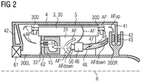
- Figure 2 shows a simplified wind turbine of figure 1 with a different air flow
- the permanent-magnet generator 3, 4 comprises an outer rotor 4 and an inner stator 3 which are connected rotatable to each other by a bearing unit 61.
- the rotor 4 comprises permanent magnets 5 facing the inner stator 3 circumferentially. In another embodiment (not shown), the magnetic fields of the magnets 5 can also be created electrically.
- the outer rotor 4 is caused to rotate about an axis of rotation R.
- Windings 30 on the inner stator 3 are cooled by guiding a cooling airflow AF via the end windings 300 into an air-gap 20 between rotor 4 and stator 3 and through the stator windings 30, and into an interior cavity 31 of the stator 3.
- This interior cavity 31 extends about a main shaft 62 around the axis of rotation R.
- the warmed air AF' drawn into the interior cavity 31 is cooled by a number of heat exchangers 15 and then blown out of the interior cavity 31 by a number of fans 14 which direct a cooled airflow AF back into a cavity 200L of the stator 3.
- the diagram shows that a winding overhang 300 - also called stator end windings 300 which is part of the stator windings 30 - extends to some distance into the cavity 200L between the rotor housing 40 and a front stator face 32 at the drive end.
- a winding overhang 300 - also called stator end windings 300 which is part of the stator windings 30 - extends to some distance into the cavity 200L between the rotor housing 40 and a front stator face 32 at the drive end.
- the cavity 200R is bounded by the cylindrical rotor housing body 40 and a brake disc 41, and is sealed off from the nacelle or canopy 44 by a suitable cover 45 or seal 45 (shown in Fig. 1 ).
- One or several brake callipers 42 are circumferentially distributed and fixed on the non-drive end of the main shaft 62.
- a brake calliper 42 comprises two brake pads 43 facing each side the brake disc 41. In braking operation, the calliper 42 or the callipers 42 presses the brake pads 43 against the opposing surfaces of the rotating brake disc 41 resulting in transforming rotational energy into heat, thus forming a wind turbine brake 41, 42, 43.
- the calliper(s) 42 with the brake pads 43 are located in the flow path AFup, AFdown as part of the warmed-up cooling air flow AF'.
- the upstream air flow AFup flows to the brake pads 43 from the air gap 20 and the stator 3.
- the downstream air flow AFdown streams away from the brake pads 43 to the non-drive end cavity 200R and the interior cavity 31 and comprises the fine brake dust 49 created by abrasion of the brake pads 43.
- An air duct 48, 50 is positioned in the downstream path AF° down in order to collect the air comprising the fine brake dust 48.
- a dust filter 46 is positioned within the air duct 48,50 between the inlet part 48 of the air duct 48, 50 and the outlet part 50 of the air duct 48, 50.
- the filter 46 can be any type of filter, e.g. a cyclone filter or a bag filter.
- the air AFdown cleaned by the filter 46 will leave the air duct 48, 50 by its outlet 50 and be further distributed to the non-drive end cavity 200R and interior cavity 31.
- the air duct 48, 50 comprises a valve 47 which can enable or stop the air flow in the air duct 48, 50.
- the valve 47 is positioned in the inlet part 48 of the air duct 48, 50.
- valve 47 is open in operation of the turbine brake 41, 42, 43 in order to collect the abraded brake dust 46 in the dust filter 46 and closed in non-braking operation in order to prevent the reduction of the cooling airflow AF created by the downstream airflow AFdown within the air duct 48, 50.
- the power of the fans 14 producing the flow of the part of the cooling air flow AFup, AFdown comprising the brake dust 49 will be increased preferably to a maximum value during operation of the wind turbine brake 41, 42, 43.
- the valve 47 can be a passive flap valve 47 opening depending on the magnitude of the downstream airflow AFdown or a or an electrical switchable, active flap valve 47.
- the collecting capacity of the filter 46 i.e. volume of the brake dust 49 the filter 46 can collect, e.g. in the filter bag or the collecting unit of the filter cyclone, should be at least as large as the volume of the brake pads 43 of the brake calliper 42.
- the filter bag of the filter 46 will be replaced or the filter cyclone of the filter 46 will be emptied if the brake pads 43 are replaced.
- the brake dust 49 will be sucked out of the filter 46 by a vacuum cleaner. This can be done in one maintenance session.
- the cooling arrangement with fans can be an "open" system in which the cooling air flow is drawn by from the outside of the wind turbine via filters and dehumidifiers into the generator. The cooling air will be warmed up by the generator and then be drawn by fans to the outside of the wind turbine.
Landscapes
- Engineering & Computer Science (AREA)
- Mechanical Engineering (AREA)
- Sustainable Development (AREA)
- Sustainable Energy (AREA)
- Chemical & Material Sciences (AREA)
- Combustion & Propulsion (AREA)
- Life Sciences & Earth Sciences (AREA)
- General Engineering & Computer Science (AREA)
- Power Engineering (AREA)
- Physics & Mathematics (AREA)
- Thermal Sciences (AREA)
- Motor Or Generator Cooling System (AREA)
- Braking Arrangements (AREA)
Claims (12)
- Turbine éolienne, comprenant- une génératrice (3,4) avec un stator (3) et un rotor (4) pour produire de l'énergie électrique,- un montage de refroidissement (1) générant un flux d'air de refroidissement (AF) pour refroidir au moins des parties de la génératrice (3,4) pendant le fonctionnement du montage de refroidissement (1),- un frein de turbine éolienne (41,42,43) comprenant un disque de frein (41) et au moins un étrier de frein (42) avec au moins un patin de frein (43), dans laquelle une partie (AFup, AFdown) du courant d'air de refroidissement (AF) s'écoule sur le au moins un patin de frein (43),- un conduit d'air (48, 50) situé en aval (AFdown) par rapport au au moins un patin de frein (43), dans laquelle le conduit d'air (48, 50) collecte la poussière de frein (49) causée par le au moins un patin de frein (43) pendant le fonctionnement du frein de turbine éolienne (41,42,43),- dans laquelle le conduit d'air (48, 50) comprend un filtre (46),- dans laquelle le filtre (46) réduit considérablement la quantité de poussière de frein (49) dans le courant de la partie du flux d'air de refroidissement (AF, AFup, AFdown).
- Turbine éolienne selon la revendication 1,
dans laquelle le conduit d'air (48, 50) comprend une vanne (47) qui autorise ou qui interdit le flux d'air passant à travers le conduit d'air (48,50), dans laquelle la vanne (47) est au moins ouverte pendant le fonctionnement du frein de turbine éolienne (41,42,43) et de préférence fermée pendant le non-fonctionnement du frein. - Turbine éolienne selon la revendication 1 ou 2,
dans laquelle le montage de refroidissement (1) comprend au moins un ventilateur (14),
dans laquelle le au moins un ventilateur (14) est capable de produire le flux d'air de refroidissement (AF). - Turbine éolienne selon l'une des revendications précédentes, dans laquelle le système de refroidissement (1) comprend un échangeur de chaleur (15), ce qui résulte en un circuit fermé de courant d'air (AF).
- Turbine éolienne selon l'une des revendications précédentes, dans laquelle le système de refroidissement comprend au moins un ventilateur (14) situé au stator (62, 3).
- Turbine éolienne selon l'une des revendications 1 à 5, dans laquelle le montage de refroidissement (x) comprend des ventilateurs tirant l'air de refroidissement de l'extérieur de la turbine éolienne via des filtres et des déshumidificateurs,
dans la génératrice (3,4),
dans laquelle le montage de refroidissement (1) comprend des ventilateurs tirant l'air de refroidissement réchauffé par la génératrice vers l'extérieur de la turbine éolienne. - Turbine éolienne selon l'une des revendications précédentes, dans laquelle la capacité de collecte de poussière du filtre (46) est au moins aussi élevée que le volume de la poussière de frein (49) créée par le au moins un patin de frein (43) de l'étrier de frein (42).
- Turbine éolienne selon l'une des revendications précédentes, dans laquelle la partie (AFup, AFdown) du flux d'air de refroidissement (AF) est chauffée par la génératrice (3,4).
- Turbine éolienne selon l'une des revendications 1 à 7,
dans laquelle la partie (AFup, AFdown) du flux d'air de refroidissement (AF) est délivrée par les ventilateurs (14) et n'est pas encore chauffée par la génératrice (3,4). - Procédé de collecte de poussière de frein (49) d'un frein de turbine éolienne (41,42,43), conduit par la turbine éolienne selon l'une des revendications précédentes, caractérisé en ce que la partie du flux d'air de refroidissement (AFdown) comprenant la poussière de frein (49) créée par le au moins un patin de frein (43) s'écoulera à travers le conduit d'air (48, 50) et sera filtré par le filtre (49) du conduit d'air (48, 50) pendant le fonctionnement du système de refroidissement.
- Procédé selon la revendication 10,
dans lequel le sac de filtre comprenant la poussière de frein (49) sera remplacé ou le filtre contenant la poussière de frein (49) sera vidé ou la poussière de frein (49) sera aspirée hors du filtre (46) par un aspirateur au plus tôt quand le au moins un patin de frein (43) devra être remplacé. - Procédé selon l'une des revendications de procédé précédentes, dans lequel la puissance des ventilateurs (14) du montage de refroidissement (1) produisant le flux de la partie du flux d'air de refroidissement (AF, AFup, AFdown) comprenant la poussière de frein (49) sera augmentée de préférence à une valeur maximum pendant le fonctionnement du frein de la turbine éolienne.
Priority Applications (4)
| Application Number | Priority Date | Filing Date | Title |
|---|---|---|---|
| EP15185338.9A EP3144528B1 (fr) | 2015-09-15 | 2015-09-15 | Éolienne dotée d'un collecteur de poussière de frein |
| US15/237,670 US10415549B2 (en) | 2015-09-15 | 2016-08-16 | Wind turbine with a brake dust collector |
| CN201621052381.9U CN206409336U (zh) | 2015-09-15 | 2016-09-13 | 带有制动灰尘收集器的风力涡轮机 |
| CN201610819820.2A CN106523287B (zh) | 2015-09-15 | 2016-09-13 | 带有制动灰尘收集器的风力涡轮机 |
Applications Claiming Priority (1)
| Application Number | Priority Date | Filing Date | Title |
|---|---|---|---|
| EP15185338.9A EP3144528B1 (fr) | 2015-09-15 | 2015-09-15 | Éolienne dotée d'un collecteur de poussière de frein |
Publications (2)
| Publication Number | Publication Date |
|---|---|
| EP3144528A1 EP3144528A1 (fr) | 2017-03-22 |
| EP3144528B1 true EP3144528B1 (fr) | 2018-03-14 |
Family
ID=54145694
Family Applications (1)
| Application Number | Title | Priority Date | Filing Date |
|---|---|---|---|
| EP15185338.9A Not-in-force EP3144528B1 (fr) | 2015-09-15 | 2015-09-15 | Éolienne dotée d'un collecteur de poussière de frein |
Country Status (3)
| Country | Link |
|---|---|
| US (1) | US10415549B2 (fr) |
| EP (1) | EP3144528B1 (fr) |
| CN (2) | CN206409336U (fr) |
Cited By (2)
| Publication number | Priority date | Publication date | Assignee | Title |
|---|---|---|---|---|
| DE102019133772A1 (de) * | 2019-12-10 | 2021-06-10 | Ostfalia Hochschule Für Angewandte Wissenschaften - Hochschule Braunschweig/Wolfenbüttel | Fahrzeug-Feinstaubsammeleinrichtung und Fahrzeug |
| DE102019133794A1 (de) * | 2019-12-10 | 2021-06-10 | Ostfalia Hochschule Für Angewandte Wissenschaften - Hochschule Braunschweig/Wolfenbüttel | Fahrzeug-Feinstaubsammeleinrichtung und Fahrzeug |
Families Citing this family (15)
| Publication number | Priority date | Publication date | Assignee | Title |
|---|---|---|---|---|
| DE102016111332B3 (de) * | 2016-06-21 | 2017-06-29 | Aerodyn Engineering Gmbh | Modular aufgebaute Windenergieanlage |
| CN110226279B (zh) * | 2017-02-02 | 2022-07-12 | 西门子歌美飒可再生能源公司 | 冷却装置 |
| EP3382199B1 (fr) * | 2017-03-27 | 2023-12-20 | Siemens Gamesa Renewable Energy A/S | Nacelle pour une éolienne comprenant un circuit de refroidissement |
| DK3482815T3 (da) * | 2017-11-08 | 2020-08-10 | Siemens Gamesa Renewable Energy As | Drift af et kølesystem i en vindmøllegenerator |
| EP3508720B1 (fr) * | 2018-01-09 | 2020-06-17 | Siemens Gamesa Renewable Energy A/S | Éolienne comportant un circuit de refroidissement |
| JP7128020B2 (ja) * | 2018-04-20 | 2022-08-30 | 曙ブレーキ工業株式会社 | 摩耗粉捕集装置、分析システム、摩耗粉捕集方法および分析方法 |
| EP3667063A1 (fr) * | 2018-12-13 | 2020-06-17 | Siemens Gamesa Renewable Energy A/S | Dispositif de drainage d'humidité dans des éoliennes |
| EP3712429A1 (fr) | 2019-03-22 | 2020-09-23 | Siemens Gamesa Renewable Energy A/S | Protection contre la foudre pour éolienne à commande directe |
| CN110195685B (zh) * | 2019-05-27 | 2020-11-27 | 上海电气风电集团股份有限公司 | 刹车系统及外转子式直驱风力发电机组 |
| CN112145380B (zh) * | 2020-11-04 | 2021-11-30 | 石家庄东方热电热力工程有限公司 | 风力发电新能源的风叶片表面灰尘刮除装置 |
| CN112576461B (zh) * | 2020-11-20 | 2022-04-08 | 中广核(乌兰察布)风力发电有限公司 | 一种偏航刹车盘扫粉装置 |
| EP4063650A1 (fr) * | 2021-03-24 | 2022-09-28 | Siemens Gamesa Renewable Energy A/S | Réduction de la densité du flux magnétique de la foudre dans les éoliennes |
| EP4116583A1 (fr) * | 2021-07-05 | 2023-01-11 | Siemens Gamesa Renewable Energy A/S | Générateur de turbine éolienne comportant un circuit de refroidissement |
| CN115026070A (zh) * | 2022-08-10 | 2022-09-09 | 哈尔滨电机厂有限责任公司 | 一种集约化一体式发电机制动除尘装置 |
| CN116021547A (zh) * | 2022-08-17 | 2023-04-28 | 深圳市大族机器人有限公司 | 关节模组及协作机器人 |
Family Cites Families (11)
| Publication number | Priority date | Publication date | Assignee | Title |
|---|---|---|---|---|
| DE50003844D1 (de) * | 1999-07-14 | 2003-10-30 | Aloys Wobben | Windenergieanlage mit einem geschlossenen kühlkreislauf |
| ATE476863T1 (de) | 2007-02-14 | 2010-08-15 | Vestas Wind Sys As | System zur rezirkulation von luft in einer komponente einer windturbine |
| WO2010022724A2 (fr) * | 2008-08-28 | 2010-03-04 | Vestas Wind Systems A/S | Filtrage de débris dans des éoliennes |
| EP2182619B1 (fr) | 2008-10-28 | 2012-10-03 | Siemens Aktiengesellschaft | Agencement pour le refroidissement d'une machine électrique |
| US7843080B2 (en) * | 2009-05-11 | 2010-11-30 | General Electric Company | Cooling system and wind turbine incorporating same |
| JP5455508B2 (ja) | 2009-08-28 | 2014-03-26 | 三菱重工業株式会社 | 風力発電用風車 |
| DK2333321T3 (en) | 2009-11-26 | 2016-09-05 | Siemens Ag | Brake system with expansion absorption agents, and the wind turbine generator |
| EP2466128B2 (fr) | 2010-12-20 | 2017-06-28 | Siemens Aktiengesellschaft | Éolienne et procédé de commande d'une éolienne et système de climatisation |
| EP2503148A1 (fr) | 2011-03-21 | 2012-09-26 | Siemens Aktiengesellschaft | Éolienne avec agencement de changement de lubrifiant liquide automatique |
| EP2899850B1 (fr) * | 2014-01-23 | 2019-11-06 | Siemens Gamesa Renewable Energy A/S | Générateur électrique pour une éolienne avec des espaces de stator variant dans le sens axial du générateur |
| EP2902619B1 (fr) | 2014-01-29 | 2018-01-17 | Siemens Aktiengesellschaft | Agencement de refroidissement pour une éolienne à entraînement direct |
-
2015
- 2015-09-15 EP EP15185338.9A patent/EP3144528B1/fr not_active Not-in-force
-
2016
- 2016-08-16 US US15/237,670 patent/US10415549B2/en not_active Expired - Fee Related
- 2016-09-13 CN CN201621052381.9U patent/CN206409336U/zh not_active Withdrawn - After Issue
- 2016-09-13 CN CN201610819820.2A patent/CN106523287B/zh not_active Expired - Fee Related
Non-Patent Citations (1)
| Title |
|---|
| None * |
Cited By (4)
| Publication number | Priority date | Publication date | Assignee | Title |
|---|---|---|---|---|
| DE102019133772A1 (de) * | 2019-12-10 | 2021-06-10 | Ostfalia Hochschule Für Angewandte Wissenschaften - Hochschule Braunschweig/Wolfenbüttel | Fahrzeug-Feinstaubsammeleinrichtung und Fahrzeug |
| DE102019133794A1 (de) * | 2019-12-10 | 2021-06-10 | Ostfalia Hochschule Für Angewandte Wissenschaften - Hochschule Braunschweig/Wolfenbüttel | Fahrzeug-Feinstaubsammeleinrichtung und Fahrzeug |
| DE102019133772B4 (de) | 2019-12-10 | 2021-08-12 | Ostfalia Hochschule Für Angewandte Wissenschaften - Hochschule Braunschweig/Wolfenbüttel | Fahrzeug-Feinstaubsammeleinrichtung und Fahrzeug |
| DE102019133794B4 (de) | 2019-12-10 | 2023-10-05 | Ostfalia Hochschule Für Angewandte Wissenschaften - Hochschule Braunschweig/Wolfenbüttel | Fahrzeug-Feinstaubsammeleinrichtung und Fahrzeug |
Also Published As
| Publication number | Publication date |
|---|---|
| US20170074251A1 (en) | 2017-03-16 |
| CN106523287A (zh) | 2017-03-22 |
| CN106523287B (zh) | 2019-05-31 |
| CN206409336U (zh) | 2017-08-15 |
| US10415549B2 (en) | 2019-09-17 |
| EP3144528A1 (fr) | 2017-03-22 |
Similar Documents
| Publication | Publication Date | Title |
|---|---|---|
| EP3144528B1 (fr) | Éolienne dotée d'un collecteur de poussière de frein | |
| CN105634210B (zh) | 采用轴流通风实现定子封闭与转子开放通风方式的电动机 | |
| JP5297236B2 (ja) | 車両用全閉形主電動機 | |
| KR20140138062A (ko) | 기류 제어 배열체 | |
| KR20150082110A (ko) | 미립자를 포획하는 브레이크 조립체 | |
| WO2020052011A1 (fr) | Mécanisme de refroidissement de moteur à grande vitesse pour compresseur d'air de pile à combustible | |
| CN103490558A (zh) | 直驱风力发电机冷却系统 | |
| CN109412339B (zh) | 电机及风力发电机组 | |
| EP3054569A1 (fr) | Agencement de refroidissement | |
| WO2012080566A1 (fr) | Machine électrique | |
| CN212033942U (zh) | 电机及风力发电机组 | |
| JP3211826B2 (ja) | 車両駆動用開放型電動機 | |
| JP2015516528A (ja) | 風力タービンの冷却システム | |
| AU2011213437A1 (en) | A radiation structure used for vertical axis disc-type external-rotor electric machine | |
| CN207513901U (zh) | 一种散热效果好的离心风机 | |
| CN202997839U (zh) | 串激电机通风系统的优化结构 | |
| CN219659490U (zh) | 一种无人机用散热防尘无刷电机 | |
| CN203522438U (zh) | 直驱风力发电机冷却系统 | |
| JP2005130693A (ja) | 全閉形電動機 | |
| CN207246063U (zh) | 一种动力集中动车组辅助变压器柜用冷却通风机 | |
| CN207638500U (zh) | 一种阻尼效应的抽风降温电机装置 | |
| CN216131124U (zh) | 一种电动矿车制动电阻风机 | |
| CN109378935A (zh) | 一种灯泡贯流式水轮发电机的外置式通风冷却系统 | |
| CN212006188U (zh) | 热交换装置 | |
| CN215633542U (zh) | 风力发电机组 |
Legal Events
| Date | Code | Title | Description |
|---|---|---|---|
| PUAI | Public reference made under article 153(3) epc to a published international application that has entered the european phase |
Free format text: ORIGINAL CODE: 0009012 |
|
| AK | Designated contracting states |
Kind code of ref document: A1 Designated state(s): AL AT BE BG CH CY CZ DE DK EE ES FI FR GB GR HR HU IE IS IT LI LT LU LV MC MK MT NL NO PL PT RO RS SE SI SK SM TR |
|
| AX | Request for extension of the european patent |
Extension state: BA ME |
|
| 17P | Request for examination filed |
Effective date: 20170519 |
|
| RBV | Designated contracting states (corrected) |
Designated state(s): AL AT BE BG CH CY CZ DE DK EE ES FI FR GB GR HR HU IE IS IT LI LT LU LV MC MK MT NL NO PL PT RO RS SE SI SK SM TR |
|
| RAP1 | Party data changed (applicant data changed or rights of an application transferred) |
Owner name: SIEMENS AKTIENGESELLSCHAFT |
|
| GRAP | Despatch of communication of intention to grant a patent |
Free format text: ORIGINAL CODE: EPIDOSNIGR1 |
|
| INTG | Intention to grant announced |
Effective date: 20171026 |
|
| GRAS | Grant fee paid |
Free format text: ORIGINAL CODE: EPIDOSNIGR3 |
|
| GRAA | (expected) grant |
Free format text: ORIGINAL CODE: 0009210 |
|
| AK | Designated contracting states |
Kind code of ref document: B1 Designated state(s): AL AT BE BG CH CY CZ DE DK EE ES FI FR GB GR HR HU IE IS IT LI LT LU LV MC MK MT NL NO PL PT RO RS SE SI SK SM TR |
|
| REG | Reference to a national code |
Ref country code: GB Ref legal event code: FG4D |
|
| REG | Reference to a national code |
Ref country code: CH Ref legal event code: EP Ref country code: AT Ref legal event code: REF Ref document number: 979152 Country of ref document: AT Kind code of ref document: T Effective date: 20180315 |
|
| REG | Reference to a national code |
Ref country code: IE Ref legal event code: FG4D |
|
| REG | Reference to a national code |
Ref country code: DE Ref legal event code: R096 Ref document number: 602015008689 Country of ref document: DE |
|
| REG | Reference to a national code |
Ref country code: NL Ref legal event code: MP Effective date: 20180314 |
|
| REG | Reference to a national code |
Ref country code: LT Ref legal event code: MG4D |
|
| PG25 | Lapsed in a contracting state [announced via postgrant information from national office to epo] |
Ref country code: CY Free format text: LAPSE BECAUSE OF FAILURE TO SUBMIT A TRANSLATION OF THE DESCRIPTION OR TO PAY THE FEE WITHIN THE PRESCRIBED TIME-LIMIT Effective date: 20180314 Ref country code: LT Free format text: LAPSE BECAUSE OF FAILURE TO SUBMIT A TRANSLATION OF THE DESCRIPTION OR TO PAY THE FEE WITHIN THE PRESCRIBED TIME-LIMIT Effective date: 20180314 Ref country code: FI Free format text: LAPSE BECAUSE OF FAILURE TO SUBMIT A TRANSLATION OF THE DESCRIPTION OR TO PAY THE FEE WITHIN THE PRESCRIBED TIME-LIMIT Effective date: 20180314 Ref country code: HR Free format text: LAPSE BECAUSE OF FAILURE TO SUBMIT A TRANSLATION OF THE DESCRIPTION OR TO PAY THE FEE WITHIN THE PRESCRIBED TIME-LIMIT Effective date: 20180314 Ref country code: NO Free format text: LAPSE BECAUSE OF FAILURE TO SUBMIT A TRANSLATION OF THE DESCRIPTION OR TO PAY THE FEE WITHIN THE PRESCRIBED TIME-LIMIT Effective date: 20180614 |
|
| REG | Reference to a national code |
Ref country code: AT Ref legal event code: MK05 Ref document number: 979152 Country of ref document: AT Kind code of ref document: T Effective date: 20180314 |
|
| PG25 | Lapsed in a contracting state [announced via postgrant information from national office to epo] |
Ref country code: GR Free format text: LAPSE BECAUSE OF FAILURE TO SUBMIT A TRANSLATION OF THE DESCRIPTION OR TO PAY THE FEE WITHIN THE PRESCRIBED TIME-LIMIT Effective date: 20180615 Ref country code: BG Free format text: LAPSE BECAUSE OF FAILURE TO SUBMIT A TRANSLATION OF THE DESCRIPTION OR TO PAY THE FEE WITHIN THE PRESCRIBED TIME-LIMIT Effective date: 20180614 Ref country code: RS Free format text: LAPSE BECAUSE OF FAILURE TO SUBMIT A TRANSLATION OF THE DESCRIPTION OR TO PAY THE FEE WITHIN THE PRESCRIBED TIME-LIMIT Effective date: 20180314 Ref country code: SE Free format text: LAPSE BECAUSE OF FAILURE TO SUBMIT A TRANSLATION OF THE DESCRIPTION OR TO PAY THE FEE WITHIN THE PRESCRIBED TIME-LIMIT Effective date: 20180314 Ref country code: LV Free format text: LAPSE BECAUSE OF FAILURE TO SUBMIT A TRANSLATION OF THE DESCRIPTION OR TO PAY THE FEE WITHIN THE PRESCRIBED TIME-LIMIT Effective date: 20180314 |
|
| REG | Reference to a national code |
Ref country code: FR Ref legal event code: PLFP Year of fee payment: 4 |
|
| PG25 | Lapsed in a contracting state [announced via postgrant information from national office to epo] |
Ref country code: RO Free format text: LAPSE BECAUSE OF FAILURE TO SUBMIT A TRANSLATION OF THE DESCRIPTION OR TO PAY THE FEE WITHIN THE PRESCRIBED TIME-LIMIT Effective date: 20180314 Ref country code: IT Free format text: LAPSE BECAUSE OF FAILURE TO SUBMIT A TRANSLATION OF THE DESCRIPTION OR TO PAY THE FEE WITHIN THE PRESCRIBED TIME-LIMIT Effective date: 20180314 Ref country code: ES Free format text: LAPSE BECAUSE OF FAILURE TO SUBMIT A TRANSLATION OF THE DESCRIPTION OR TO PAY THE FEE WITHIN THE PRESCRIBED TIME-LIMIT Effective date: 20180314 Ref country code: PL Free format text: LAPSE BECAUSE OF FAILURE TO SUBMIT A TRANSLATION OF THE DESCRIPTION OR TO PAY THE FEE WITHIN THE PRESCRIBED TIME-LIMIT Effective date: 20180314 Ref country code: NL Free format text: LAPSE BECAUSE OF FAILURE TO SUBMIT A TRANSLATION OF THE DESCRIPTION OR TO PAY THE FEE WITHIN THE PRESCRIBED TIME-LIMIT Effective date: 20180314 Ref country code: EE Free format text: LAPSE BECAUSE OF FAILURE TO SUBMIT A TRANSLATION OF THE DESCRIPTION OR TO PAY THE FEE WITHIN THE PRESCRIBED TIME-LIMIT Effective date: 20180314 Ref country code: AL Free format text: LAPSE BECAUSE OF FAILURE TO SUBMIT A TRANSLATION OF THE DESCRIPTION OR TO PAY THE FEE WITHIN THE PRESCRIBED TIME-LIMIT Effective date: 20180314 |
|
| PG25 | Lapsed in a contracting state [announced via postgrant information from national office to epo] |
Ref country code: SM Free format text: LAPSE BECAUSE OF FAILURE TO SUBMIT A TRANSLATION OF THE DESCRIPTION OR TO PAY THE FEE WITHIN THE PRESCRIBED TIME-LIMIT Effective date: 20180314 Ref country code: SK Free format text: LAPSE BECAUSE OF FAILURE TO SUBMIT A TRANSLATION OF THE DESCRIPTION OR TO PAY THE FEE WITHIN THE PRESCRIBED TIME-LIMIT Effective date: 20180314 Ref country code: AT Free format text: LAPSE BECAUSE OF FAILURE TO SUBMIT A TRANSLATION OF THE DESCRIPTION OR TO PAY THE FEE WITHIN THE PRESCRIBED TIME-LIMIT Effective date: 20180314 Ref country code: CZ Free format text: LAPSE BECAUSE OF FAILURE TO SUBMIT A TRANSLATION OF THE DESCRIPTION OR TO PAY THE FEE WITHIN THE PRESCRIBED TIME-LIMIT Effective date: 20180314 |
|
| REG | Reference to a national code |
Ref country code: DE Ref legal event code: R097 Ref document number: 602015008689 Country of ref document: DE |
|
| PG25 | Lapsed in a contracting state [announced via postgrant information from national office to epo] |
Ref country code: PT Free format text: LAPSE BECAUSE OF FAILURE TO SUBMIT A TRANSLATION OF THE DESCRIPTION OR TO PAY THE FEE WITHIN THE PRESCRIBED TIME-LIMIT Effective date: 20180716 |
|
| PLBE | No opposition filed within time limit |
Free format text: ORIGINAL CODE: 0009261 |
|
| STAA | Information on the status of an ep patent application or granted ep patent |
Free format text: STATUS: NO OPPOSITION FILED WITHIN TIME LIMIT |
|
| PG25 | Lapsed in a contracting state [announced via postgrant information from national office to epo] |
Ref country code: DK Free format text: LAPSE BECAUSE OF FAILURE TO SUBMIT A TRANSLATION OF THE DESCRIPTION OR TO PAY THE FEE WITHIN THE PRESCRIBED TIME-LIMIT Effective date: 20180314 |
|
| 26N | No opposition filed |
Effective date: 20181217 |
|
| PG25 | Lapsed in a contracting state [announced via postgrant information from national office to epo] |
Ref country code: SI Free format text: LAPSE BECAUSE OF FAILURE TO SUBMIT A TRANSLATION OF THE DESCRIPTION OR TO PAY THE FEE WITHIN THE PRESCRIBED TIME-LIMIT Effective date: 20180314 |
|
| PG25 | Lapsed in a contracting state [announced via postgrant information from national office to epo] |
Ref country code: MC Free format text: LAPSE BECAUSE OF FAILURE TO SUBMIT A TRANSLATION OF THE DESCRIPTION OR TO PAY THE FEE WITHIN THE PRESCRIBED TIME-LIMIT Effective date: 20180314 |
|
| REG | Reference to a national code |
Ref country code: CH Ref legal event code: PL |
|
| REG | Reference to a national code |
Ref country code: BE Ref legal event code: MM Effective date: 20180930 |
|
| REG | Reference to a national code |
Ref country code: IE Ref legal event code: MM4A |
|
| PG25 | Lapsed in a contracting state [announced via postgrant information from national office to epo] |
Ref country code: LU Free format text: LAPSE BECAUSE OF NON-PAYMENT OF DUE FEES Effective date: 20180915 |
|
| REG | Reference to a national code |
Ref country code: DE Ref legal event code: R081 Ref document number: 602015008689 Country of ref document: DE Owner name: SIEMENS GAMESA RENEWABLE ENERGY A/S, DK Free format text: FORMER OWNER: SIEMENS AKTIENGESELLSCHAFT, 80333 MUENCHEN, DE |
|
| PG25 | Lapsed in a contracting state [announced via postgrant information from national office to epo] |
Ref country code: IE Free format text: LAPSE BECAUSE OF NON-PAYMENT OF DUE FEES Effective date: 20180915 |
|
| PG25 | Lapsed in a contracting state [announced via postgrant information from national office to epo] |
Ref country code: BE Free format text: LAPSE BECAUSE OF NON-PAYMENT OF DUE FEES Effective date: 20180930 Ref country code: CH Free format text: LAPSE BECAUSE OF NON-PAYMENT OF DUE FEES Effective date: 20180930 Ref country code: LI Free format text: LAPSE BECAUSE OF NON-PAYMENT OF DUE FEES Effective date: 20180930 |
|
| REG | Reference to a national code |
Ref country code: GB Ref legal event code: 732E Free format text: REGISTERED BETWEEN 20191128 AND 20191204 |
|
| PG25 | Lapsed in a contracting state [announced via postgrant information from national office to epo] |
Ref country code: MT Free format text: LAPSE BECAUSE OF NON-PAYMENT OF DUE FEES Effective date: 20180915 |
|
| PG25 | Lapsed in a contracting state [announced via postgrant information from national office to epo] |
Ref country code: TR Free format text: LAPSE BECAUSE OF FAILURE TO SUBMIT A TRANSLATION OF THE DESCRIPTION OR TO PAY THE FEE WITHIN THE PRESCRIBED TIME-LIMIT Effective date: 20180314 |
|
| PG25 | Lapsed in a contracting state [announced via postgrant information from national office to epo] |
Ref country code: HU Free format text: LAPSE BECAUSE OF FAILURE TO SUBMIT A TRANSLATION OF THE DESCRIPTION OR TO PAY THE FEE WITHIN THE PRESCRIBED TIME-LIMIT; INVALID AB INITIO Effective date: 20150915 Ref country code: MK Free format text: LAPSE BECAUSE OF NON-PAYMENT OF DUE FEES Effective date: 20180314 |
|
| PG25 | Lapsed in a contracting state [announced via postgrant information from national office to epo] |
Ref country code: IS Free format text: LAPSE BECAUSE OF FAILURE TO SUBMIT A TRANSLATION OF THE DESCRIPTION OR TO PAY THE FEE WITHIN THE PRESCRIBED TIME-LIMIT Effective date: 20180714 |
|
| PGFP | Annual fee paid to national office [announced via postgrant information from national office to epo] |
Ref country code: FR Payment date: 20210920 Year of fee payment: 7 |
|
| PGFP | Annual fee paid to national office [announced via postgrant information from national office to epo] |
Ref country code: DE Payment date: 20211020 Year of fee payment: 7 Ref country code: GB Payment date: 20211022 Year of fee payment: 7 |
|
| REG | Reference to a national code |
Ref country code: DE Ref legal event code: R119 Ref document number: 602015008689 Country of ref document: DE |
|
| GBPC | Gb: european patent ceased through non-payment of renewal fee |
Effective date: 20220915 |
|
| PG25 | Lapsed in a contracting state [announced via postgrant information from national office to epo] |
Ref country code: FR Free format text: LAPSE BECAUSE OF NON-PAYMENT OF DUE FEES Effective date: 20220930 Ref country code: DE Free format text: LAPSE BECAUSE OF NON-PAYMENT OF DUE FEES Effective date: 20230401 |
|
| PG25 | Lapsed in a contracting state [announced via postgrant information from national office to epo] |
Ref country code: GB Free format text: LAPSE BECAUSE OF NON-PAYMENT OF DUE FEES Effective date: 20220915 |