EP3142168A1 - Module de stockage d'énergie - Google Patents
Module de stockage d'énergie Download PDFInfo
- Publication number
- EP3142168A1 EP3142168A1 EP15789377.7A EP15789377A EP3142168A1 EP 3142168 A1 EP3142168 A1 EP 3142168A1 EP 15789377 A EP15789377 A EP 15789377A EP 3142168 A1 EP3142168 A1 EP 3142168A1
- Authority
- EP
- European Patent Office
- Prior art keywords
- terminal
- power storage
- stacked
- connection
- storage elements
- Prior art date
- Legal status (The legal status is an assumption and is not a legal conclusion. Google has not performed a legal analysis and makes no representation as to the accuracy of the status listed.)
- Granted
Links
- 238000003860 storage Methods 0.000 title claims abstract description 135
- 230000005611 electricity Effects 0.000 claims abstract description 24
- 238000001514 detection method Methods 0.000 description 44
- 230000004308 accommodation Effects 0.000 description 20
- 238000000034 method Methods 0.000 description 7
- 230000000694 effects Effects 0.000 description 5
- 238000003466 welding Methods 0.000 description 5
- 229910000838 Al alloy Inorganic materials 0.000 description 4
- 229910052782 aluminium Inorganic materials 0.000 description 4
- XAGFODPZIPBFFR-UHFFFAOYSA-N aluminium Chemical compound [Al] XAGFODPZIPBFFR-UHFFFAOYSA-N 0.000 description 4
- 239000007769 metal material Substances 0.000 description 4
- RYGMFSIKBFXOCR-UHFFFAOYSA-N Copper Chemical compound [Cu] RYGMFSIKBFXOCR-UHFFFAOYSA-N 0.000 description 3
- 229910000881 Cu alloy Inorganic materials 0.000 description 3
- 229910052802 copper Inorganic materials 0.000 description 3
- 239000010949 copper Substances 0.000 description 3
- 230000000717 retained effect Effects 0.000 description 3
- 238000005219 brazing Methods 0.000 description 2
- 239000004020 conductor Substances 0.000 description 2
- 238000010586 diagram Methods 0.000 description 2
- 239000000463 material Substances 0.000 description 2
- 239000011347 resin Substances 0.000 description 2
- 229920005989 resin Polymers 0.000 description 2
- 238000005476 soldering Methods 0.000 description 2
- 238000007664 blowing Methods 0.000 description 1
- 239000003990 capacitor Substances 0.000 description 1
- 238000002788 crimping Methods 0.000 description 1
- 239000011810 insulating material Substances 0.000 description 1
- 239000005001 laminate film Substances 0.000 description 1
- 229910052751 metal Inorganic materials 0.000 description 1
- 239000002184 metal Substances 0.000 description 1
- 238000003825 pressing Methods 0.000 description 1
Images


Classifications
-
- H—ELECTRICITY
- H01—ELECTRIC ELEMENTS
- H01G—CAPACITORS; CAPACITORS, RECTIFIERS, DETECTORS, SWITCHING DEVICES OR LIGHT-SENSITIVE DEVICES, OF THE ELECTROLYTIC TYPE
- H01G2/00—Details of capacitors not covered by a single one of groups H01G4/00-H01G11/00
- H01G2/02—Mountings
- H01G2/04—Mountings specially adapted for mounting on a chassis
-
- H—ELECTRICITY
- H01—ELECTRIC ELEMENTS
- H01G—CAPACITORS; CAPACITORS, RECTIFIERS, DETECTORS, SWITCHING DEVICES OR LIGHT-SENSITIVE DEVICES, OF THE ELECTROLYTIC TYPE
- H01G11/00—Hybrid capacitors, i.e. capacitors having different positive and negative electrodes; Electric double-layer [EDL] capacitors; Processes for the manufacture thereof or of parts thereof
- H01G11/10—Multiple hybrid or EDL capacitors, e.g. arrays or modules
- H01G11/12—Stacked hybrid or EDL capacitors
-
- H—ELECTRICITY
- H01—ELECTRIC ELEMENTS
- H01G—CAPACITORS; CAPACITORS, RECTIFIERS, DETECTORS, SWITCHING DEVICES OR LIGHT-SENSITIVE DEVICES, OF THE ELECTROLYTIC TYPE
- H01G11/00—Hybrid capacitors, i.e. capacitors having different positive and negative electrodes; Electric double-layer [EDL] capacitors; Processes for the manufacture thereof or of parts thereof
- H01G11/14—Arrangements or processes for adjusting or protecting hybrid or EDL capacitors
- H01G11/16—Arrangements or processes for adjusting or protecting hybrid or EDL capacitors against electric overloads, e.g. including fuses
-
- H—ELECTRICITY
- H01—ELECTRIC ELEMENTS
- H01G—CAPACITORS; CAPACITORS, RECTIFIERS, DETECTORS, SWITCHING DEVICES OR LIGHT-SENSITIVE DEVICES, OF THE ELECTROLYTIC TYPE
- H01G11/00—Hybrid capacitors, i.e. capacitors having different positive and negative electrodes; Electric double-layer [EDL] capacitors; Processes for the manufacture thereof or of parts thereof
- H01G11/74—Terminals, e.g. extensions of current collectors
- H01G11/76—Terminals, e.g. extensions of current collectors specially adapted for integration in multiple or stacked hybrid or EDL capacitors
-
- H—ELECTRICITY
- H01—ELECTRIC ELEMENTS
- H01G—CAPACITORS; CAPACITORS, RECTIFIERS, DETECTORS, SWITCHING DEVICES OR LIGHT-SENSITIVE DEVICES, OF THE ELECTROLYTIC TYPE
- H01G9/00—Electrolytic capacitors, rectifiers, detectors, switching devices, light-sensitive or temperature-sensitive devices; Processes of their manufacture
- H01G9/0003—Protection against electric or thermal overload; cooling arrangements; means for avoiding the formation of cathode films
-
- H—ELECTRICITY
- H01—ELECTRIC ELEMENTS
- H01G—CAPACITORS; CAPACITORS, RECTIFIERS, DETECTORS, SWITCHING DEVICES OR LIGHT-SENSITIVE DEVICES, OF THE ELECTROLYTIC TYPE
- H01G9/00—Electrolytic capacitors, rectifiers, detectors, switching devices, light-sensitive or temperature-sensitive devices; Processes of their manufacture
- H01G9/004—Details
- H01G9/008—Terminals
-
- H—ELECTRICITY
- H01—ELECTRIC ELEMENTS
- H01G—CAPACITORS; CAPACITORS, RECTIFIERS, DETECTORS, SWITCHING DEVICES OR LIGHT-SENSITIVE DEVICES, OF THE ELECTROLYTIC TYPE
- H01G9/00—Electrolytic capacitors, rectifiers, detectors, switching devices, light-sensitive or temperature-sensitive devices; Processes of their manufacture
- H01G9/004—Details
- H01G9/08—Housing; Encapsulation
-
- H—ELECTRICITY
- H01—ELECTRIC ELEMENTS
- H01M—PROCESSES OR MEANS, e.g. BATTERIES, FOR THE DIRECT CONVERSION OF CHEMICAL ENERGY INTO ELECTRICAL ENERGY
- H01M10/00—Secondary cells; Manufacture thereof
- H01M10/42—Methods or arrangements for servicing or maintenance of secondary cells or secondary half-cells
- H01M10/48—Accumulators combined with arrangements for measuring, testing or indicating the condition of cells, e.g. the level or density of the electrolyte
- H01M10/482—Accumulators combined with arrangements for measuring, testing or indicating the condition of cells, e.g. the level or density of the electrolyte for several batteries or cells simultaneously or sequentially
-
- H—ELECTRICITY
- H01—ELECTRIC ELEMENTS
- H01M—PROCESSES OR MEANS, e.g. BATTERIES, FOR THE DIRECT CONVERSION OF CHEMICAL ENERGY INTO ELECTRICAL ENERGY
- H01M50/00—Constructional details or processes of manufacture of the non-active parts of electrochemical cells other than fuel cells, e.g. hybrid cells
- H01M50/20—Mountings; Secondary casings or frames; Racks, modules or packs; Suspension devices; Shock absorbers; Transport or carrying devices; Holders
- H01M50/204—Racks, modules or packs for multiple batteries or multiple cells
- H01M50/207—Racks, modules or packs for multiple batteries or multiple cells characterised by their shape
- H01M50/209—Racks, modules or packs for multiple batteries or multiple cells characterised by their shape adapted for prismatic or rectangular cells
-
- H—ELECTRICITY
- H01—ELECTRIC ELEMENTS
- H01M—PROCESSES OR MEANS, e.g. BATTERIES, FOR THE DIRECT CONVERSION OF CHEMICAL ENERGY INTO ELECTRICAL ENERGY
- H01M50/00—Constructional details or processes of manufacture of the non-active parts of electrochemical cells other than fuel cells, e.g. hybrid cells
- H01M50/20—Mountings; Secondary casings or frames; Racks, modules or packs; Suspension devices; Shock absorbers; Transport or carrying devices; Holders
- H01M50/296—Mountings; Secondary casings or frames; Racks, modules or packs; Suspension devices; Shock absorbers; Transport or carrying devices; Holders characterised by terminals of battery packs
-
- H—ELECTRICITY
- H01—ELECTRIC ELEMENTS
- H01M—PROCESSES OR MEANS, e.g. BATTERIES, FOR THE DIRECT CONVERSION OF CHEMICAL ENERGY INTO ELECTRICAL ENERGY
- H01M50/00—Constructional details or processes of manufacture of the non-active parts of electrochemical cells other than fuel cells, e.g. hybrid cells
- H01M50/50—Current conducting connections for cells or batteries
- H01M50/502—Interconnectors for connecting terminals of adjacent batteries; Interconnectors for connecting cells outside a battery casing
- H01M50/507—Interconnectors for connecting terminals of adjacent batteries; Interconnectors for connecting cells outside a battery casing comprising an arrangement of two or more busbars within a container structure, e.g. busbar modules
-
- H—ELECTRICITY
- H01—ELECTRIC ELEMENTS
- H01M—PROCESSES OR MEANS, e.g. BATTERIES, FOR THE DIRECT CONVERSION OF CHEMICAL ENERGY INTO ELECTRICAL ENERGY
- H01M50/00—Constructional details or processes of manufacture of the non-active parts of electrochemical cells other than fuel cells, e.g. hybrid cells
- H01M50/50—Current conducting connections for cells or batteries
- H01M50/543—Terminals
- H01M50/547—Terminals characterised by the disposition of the terminals on the cells
- H01M50/548—Terminals characterised by the disposition of the terminals on the cells on opposite sides of the cell
-
- H—ELECTRICITY
- H01—ELECTRIC ELEMENTS
- H01M—PROCESSES OR MEANS, e.g. BATTERIES, FOR THE DIRECT CONVERSION OF CHEMICAL ENERGY INTO ELECTRICAL ENERGY
- H01M50/00—Constructional details or processes of manufacture of the non-active parts of electrochemical cells other than fuel cells, e.g. hybrid cells
- H01M50/50—Current conducting connections for cells or batteries
- H01M50/572—Means for preventing undesired use or discharge
- H01M50/574—Devices or arrangements for the interruption of current
- H01M50/581—Devices or arrangements for the interruption of current in response to temperature
-
- H—ELECTRICITY
- H01—ELECTRIC ELEMENTS
- H01M—PROCESSES OR MEANS, e.g. BATTERIES, FOR THE DIRECT CONVERSION OF CHEMICAL ENERGY INTO ELECTRICAL ENERGY
- H01M50/00—Constructional details or processes of manufacture of the non-active parts of electrochemical cells other than fuel cells, e.g. hybrid cells
- H01M50/50—Current conducting connections for cells or batteries
- H01M50/572—Means for preventing undesired use or discharge
- H01M50/574—Devices or arrangements for the interruption of current
- H01M50/583—Devices or arrangements for the interruption of current in response to current, e.g. fuses
-
- H—ELECTRICITY
- H01—ELECTRIC ELEMENTS
- H01M—PROCESSES OR MEANS, e.g. BATTERIES, FOR THE DIRECT CONVERSION OF CHEMICAL ENERGY INTO ELECTRICAL ENERGY
- H01M10/00—Secondary cells; Manufacture thereof
- H01M10/42—Methods or arrangements for servicing or maintenance of secondary cells or secondary half-cells
- H01M10/48—Accumulators combined with arrangements for measuring, testing or indicating the condition of cells, e.g. the level or density of the electrolyte
-
- H—ELECTRICITY
- H01—ELECTRIC ELEMENTS
- H01M—PROCESSES OR MEANS, e.g. BATTERIES, FOR THE DIRECT CONVERSION OF CHEMICAL ENERGY INTO ELECTRICAL ENERGY
- H01M10/00—Secondary cells; Manufacture thereof
- H01M10/60—Heating or cooling; Temperature control
- H01M10/61—Types of temperature control
- H01M10/613—Cooling or keeping cold
-
- H—ELECTRICITY
- H01—ELECTRIC ELEMENTS
- H01M—PROCESSES OR MEANS, e.g. BATTERIES, FOR THE DIRECT CONVERSION OF CHEMICAL ENERGY INTO ELECTRICAL ENERGY
- H01M10/00—Secondary cells; Manufacture thereof
- H01M10/60—Heating or cooling; Temperature control
- H01M10/62—Heating or cooling; Temperature control specially adapted for specific applications
- H01M10/625—Vehicles
-
- H—ELECTRICITY
- H01—ELECTRIC ELEMENTS
- H01M—PROCESSES OR MEANS, e.g. BATTERIES, FOR THE DIRECT CONVERSION OF CHEMICAL ENERGY INTO ELECTRICAL ENERGY
- H01M10/00—Secondary cells; Manufacture thereof
- H01M10/60—Heating or cooling; Temperature control
- H01M10/64—Heating or cooling; Temperature control characterised by the shape of the cells
- H01M10/647—Prismatic or flat cells, e.g. pouch cells
-
- H—ELECTRICITY
- H01—ELECTRIC ELEMENTS
- H01M—PROCESSES OR MEANS, e.g. BATTERIES, FOR THE DIRECT CONVERSION OF CHEMICAL ENERGY INTO ELECTRICAL ENERGY
- H01M10/00—Secondary cells; Manufacture thereof
- H01M10/60—Heating or cooling; Temperature control
- H01M10/65—Means for temperature control structurally associated with the cells
- H01M10/655—Solid structures for heat exchange or heat conduction
- H01M10/6554—Rods or plates
- H01M10/6555—Rods or plates arranged between the cells
-
- H—ELECTRICITY
- H01—ELECTRIC ELEMENTS
- H01M—PROCESSES OR MEANS, e.g. BATTERIES, FOR THE DIRECT CONVERSION OF CHEMICAL ENERGY INTO ELECTRICAL ENERGY
- H01M2200/00—Safety devices for primary or secondary batteries
- H01M2200/10—Temperature sensitive devices
- H01M2200/103—Fuse
-
- H—ELECTRICITY
- H01—ELECTRIC ELEMENTS
- H01M—PROCESSES OR MEANS, e.g. BATTERIES, FOR THE DIRECT CONVERSION OF CHEMICAL ENERGY INTO ELECTRICAL ENERGY
- H01M50/00—Constructional details or processes of manufacture of the non-active parts of electrochemical cells other than fuel cells, e.g. hybrid cells
- H01M50/20—Mountings; Secondary casings or frames; Racks, modules or packs; Suspension devices; Shock absorbers; Transport or carrying devices; Holders
- H01M50/262—Mountings; Secondary casings or frames; Racks, modules or packs; Suspension devices; Shock absorbers; Transport or carrying devices; Holders with fastening means, e.g. locks
-
- H—ELECTRICITY
- H01—ELECTRIC ELEMENTS
- H01M—PROCESSES OR MEANS, e.g. BATTERIES, FOR THE DIRECT CONVERSION OF CHEMICAL ENERGY INTO ELECTRICAL ENERGY
- H01M50/00—Constructional details or processes of manufacture of the non-active parts of electrochemical cells other than fuel cells, e.g. hybrid cells
- H01M50/50—Current conducting connections for cells or batteries
- H01M50/502—Interconnectors for connecting terminals of adjacent batteries; Interconnectors for connecting cells outside a battery casing
- H01M50/514—Methods for interconnecting adjacent batteries or cells
- H01M50/516—Methods for interconnecting adjacent batteries or cells by welding, soldering or brazing
-
- H—ELECTRICITY
- H01—ELECTRIC ELEMENTS
- H01M—PROCESSES OR MEANS, e.g. BATTERIES, FOR THE DIRECT CONVERSION OF CHEMICAL ENERGY INTO ELECTRICAL ENERGY
- H01M50/00—Constructional details or processes of manufacture of the non-active parts of electrochemical cells other than fuel cells, e.g. hybrid cells
- H01M50/50—Current conducting connections for cells or batteries
- H01M50/502—Interconnectors for connecting terminals of adjacent batteries; Interconnectors for connecting cells outside a battery casing
- H01M50/521—Interconnectors for connecting terminals of adjacent batteries; Interconnectors for connecting cells outside a battery casing characterised by the material
- H01M50/522—Inorganic material
-
- H—ELECTRICITY
- H01—ELECTRIC ELEMENTS
- H01M—PROCESSES OR MEANS, e.g. BATTERIES, FOR THE DIRECT CONVERSION OF CHEMICAL ENERGY INTO ELECTRICAL ENERGY
- H01M50/00—Constructional details or processes of manufacture of the non-active parts of electrochemical cells other than fuel cells, e.g. hybrid cells
- H01M50/50—Current conducting connections for cells or batteries
- H01M50/569—Constructional details of current conducting connections for detecting conditions inside cells or batteries, e.g. details of voltage sensing terminals
-
- Y—GENERAL TAGGING OF NEW TECHNOLOGICAL DEVELOPMENTS; GENERAL TAGGING OF CROSS-SECTIONAL TECHNOLOGIES SPANNING OVER SEVERAL SECTIONS OF THE IPC; TECHNICAL SUBJECTS COVERED BY FORMER USPC CROSS-REFERENCE ART COLLECTIONS [XRACs] AND DIGESTS
- Y02—TECHNOLOGIES OR APPLICATIONS FOR MITIGATION OR ADAPTATION AGAINST CLIMATE CHANGE
- Y02E—REDUCTION OF GREENHOUSE GAS [GHG] EMISSIONS, RELATED TO ENERGY GENERATION, TRANSMISSION OR DISTRIBUTION
- Y02E60/00—Enabling technologies; Technologies with a potential or indirect contribution to GHG emissions mitigation
- Y02E60/10—Energy storage using batteries
-
- Y—GENERAL TAGGING OF NEW TECHNOLOGICAL DEVELOPMENTS; GENERAL TAGGING OF CROSS-SECTIONAL TECHNOLOGIES SPANNING OVER SEVERAL SECTIONS OF THE IPC; TECHNICAL SUBJECTS COVERED BY FORMER USPC CROSS-REFERENCE ART COLLECTIONS [XRACs] AND DIGESTS
- Y02—TECHNOLOGIES OR APPLICATIONS FOR MITIGATION OR ADAPTATION AGAINST CLIMATE CHANGE
- Y02E—REDUCTION OF GREENHOUSE GAS [GHG] EMISSIONS, RELATED TO ENERGY GENERATION, TRANSMISSION OR DISTRIBUTION
- Y02E60/00—Enabling technologies; Technologies with a potential or indirect contribution to GHG emissions mitigation
- Y02E60/13—Energy storage using capacitors
-
- Y—GENERAL TAGGING OF NEW TECHNOLOGICAL DEVELOPMENTS; GENERAL TAGGING OF CROSS-SECTIONAL TECHNOLOGIES SPANNING OVER SEVERAL SECTIONS OF THE IPC; TECHNICAL SUBJECTS COVERED BY FORMER USPC CROSS-REFERENCE ART COLLECTIONS [XRACs] AND DIGESTS
- Y02—TECHNOLOGIES OR APPLICATIONS FOR MITIGATION OR ADAPTATION AGAINST CLIMATE CHANGE
- Y02T—CLIMATE CHANGE MITIGATION TECHNOLOGIES RELATED TO TRANSPORTATION
- Y02T10/00—Road transport of goods or passengers
- Y02T10/60—Other road transportation technologies with climate change mitigation effect
- Y02T10/70—Energy storage systems for electromobility, e.g. batteries
Definitions
- the present invention relates to an electricity storage module.
- battery modules mounted on electric cars or hybrid vehicles are constituted by connecting multiple electric cells in series or in parallel with each other via bus bars.
- Such a battery module includes a terminal for detecting a state of an electric cell group (voltage, temperature, or the like) and an electric wire for connecting the terminal and a controller for an ECU or the like (see Patent Document 1, for example).
- Patent Document 1 JP 2011-91003A
- a voltage detection terminal to which a voltage detection electric wire is crimped is bolted to the electrode together with the bus bar for connecting the electric cells, and accordingly, the voltage detection terminal can be electrically connected to the controller for controlling the electric cell group and the battery, such as an ECU.
- the battery module including the electric cell group obtained by stacking a plurality of electric cells
- the detection terminal and the external device are connected to each other using a connector
- the position at which the connector and the detection terminal are connected to each other shifts due to tolerances in the direction in which the electric cells are stacked. Therefore, it has been necessary to use a connector having a structure that gives consideration to tolerances in the direction in which the electric cells are stacked.
- An object of the present invention is to provide an electricity storage module that can accommodate tolerances in the direction in which the power storage elements are stacked, even with a simple configuration.
- An aspect of the present invention is an electricity storage module including a power storage element group obtained by stacking a plurality of power storage elements each having a lead terminal, a connection member that is electrically connected to the lead terminal, a connector for electrically connecting the connection member to an external device, and a terminal member for electrically connecting the connection member to the connector, the connection member having a connection portion that is disposed in parallel with a direction in which the power storage elements are stacked, and that is connected to the terminal member, and the terminal member being connected to the connection portion in a state in which the terminal member is movable in the direction in which the power storage elements are stacked.
- connection member has a connection portion that is disposed in parallel with a direction in which the power storage elements are stacked, and that is connected to the terminal member, and the terminal member is connected to the connection portion in a state in which the terminal member is movable in the direction in which the power storage elements are stacked. Therefore, tolerances in the direction in which the power storage elements are stacked can be accommodated due to the terminal member moving in the direction in which the power storage elements are stacked.
- tolerances in the direction in which the power storage elements are stacked can be accommodated only with a configuration in which the connection portion of the connection member is disposed in parallel with the direction in which the power storage elements are stacked and a configuration in which the terminal member is connected to the connection member (the connection portion) movable in the stacking direction, and thus, tolerances in the direction in which the power storage elements are stacked can be accommodated even with a simple configuration.
- the present invention may have the following configurations.
- the connector may include a housing for holding the terminal member in a state in which the terminal member is electrically connected to the connection member while the terminal member is allowed to move in the direction in which the power storage elements are stacked.
- the terminal member that is allowed to move in the direction in which the power storage elements are stacked passes a position at which the terminal member is connected to the connection member, there is a concern that a state of electrical connection with the connection member will deteriorate.
- the terminal member is held in a state in which the terminal member is electrically connected to the connection member while the terminal member is allowed to move in the direction in which the power storage elements are stacked, and thus, it is possible to ensure the state in which the terminal member and the connection member are electrically connected to each other.
- the connector may be provided with a fuse mounting portion for mounting a fuse that is to be electrically connected to the lead terminal.
- Embodiment 1 of the present invention will be described with reference to FIGS. 1 to 28 .
- reference signs may be given to only one member of a plurality of the same members, and reference signs may be omitted from the other same members.
- the terms front and back respectively refer to the left side and right side of FIG. 1 .
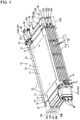
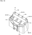
- an electricity storage module 10 of the present embodiment includes a power storage element group 11 obtained by stacking a plurality of power storage elements 12 (six in the present embodiment).
- any power storage elements 12 such as secondary batteries, capacitors, and condensers can be used as the power storage elements 12 as needed.
- a secondary battery is used as the power storage element 12 according to the present embodiment.
- the electricity storage module 10 of the present embodiment includes a stacked object 20 obtained by stacking six power storage units 21 each obtained by placing the power storage element 12 on a heat transfer member 22 to which a holding member 30 is attached.
- the power storage unit that is disposed at the lowermost stage is denoted as a first power storage unit 21A
- the power storage units that are disposed at a second stage to a fifth stage from the bottom are denoted as second power storage units 21B
- the power storage unit that is disposed at the uppermost stage is denoted as a third power storage unit 21C.
- Each of the power storage units 21 includes a heat transfer member 22 to which the holding members 30 are attached to both ends in its longitudinal direction, and a power storage element 12 that is placed on the heat transfer member 22 and held by the holding member 30.
- the heat transfer member 22 is a member made of a heat conductive material.
- aluminum or an aluminum alloy which has excellent heat conductivity, is used as the heat conductive material.
- four heat conductive walls 23 that each arise upward are formed spaced apart from each other at a pair of side edges extending in the longitudinal direction of the heat transfer member 22. These heat conductive walls 23 are disposed in contact with an inner wall surface of a case when the stacked object 20 is accommodated in the case (not shown), and has a function of transmitting heat generated from the power storage elements 12 to the case.
- the heat that is generated from the power storage elements 12 travels to the case via the heat conductive walls 23, and is radiated to the outside of the case.
- the holding members 30 made of an insulating resin material are attached to both ends in the longitudinal direction of the heat transfer member 22, and the power storage element 12 is placed on the upper surface of the heat transfer member 22.
- the power storage element 12 has an approximately rectangular shape when viewed from the above.
- the power storage element 12 includes a container 13 obtained by welding side edges of a pair of laminate films each having an substantially rectangular shape, a power storage element (not shown) that is accommodated inside the container 13, and the lead terminals 14 that are connected to the power storage element inside the container 13 and drawn from the side edges of the container 13 to the outside.
- the polarity of the lead terminal 14 that is drawn from the edge on one side (side edge) of the container 13 is different from the polarity of the lead terminal 14 that is drawn from the edge on the other side.
- the power storage elements 12 that are placed on each other in the stacking direction are connected in series or in parallel with each other by disposing the lead terminals 14 of the power storage elements 12 over one another.
- the ends of the lead terminals 14 that are adjacent to each other in the stacking direction are bent perpendicularly upward or perpendicularly downward, and are laid over each other.
- the power storage elements 12 that are overlaid in the stacking direction are connected in series by electrically connecting the lead terminals 14 having opposite polarities.
- the lead terminals 14 that are adjacent to each other in the stacking direction can be connected by a known method such as welding, soldering, or brazing.
- a metallic voltage detection bus bar 43 (an example of a connection member) for detecting voltage of the power storage element 12 is connected to the lead terminal 14 with a known method such as welding, soldering, or brazing.
- the holding member 30 made of the insulating material is provided with two through holes 31 into which fixing members (not shown) are insertable.
- a power storage element holding portion 32 is formed in each holding member 30, the power storage element holding portion 32 having a recessed shape into which a corner 15A of a wider region 15 of the lead terminal 14 is fitted. Movement of the lead terminal 14 (the power storage element 12) is restricted by this power storage element holding unit 32.
- a rearward one of the two holding members 30 that are part of the first power storage unit 21A at the lowermost stage is a first holding member 30A (see FIG. 17 ), and a frontward one of those two holding members 30 is a second holding member 30B (see FIG. 18 ).
- One of the two holding members 30 that are part of the second power storage units 21B at the second to fifth stages from the bottom is a third holding member 30C (see FIG. 19 ), and the other of those two holding members 30 is a fourth holding member 30D (see FIG. 20 ).
- the third holding member 30C is disposed rearward, and the fourth holding member 30D is disposed frontward at the second and fourth stages.
- the third holding member 30C is disposed frontward, and the fourth holding member 30D is disposed rearward at the third and fifth stages.
- a rearward one of the two holding members 30 that are part of the third power storage unit 21C at the uppermost stage is a fifth holding member 30E (see FIG. 21 ), and a frontward one of those holding members 30 is a sixth holding member 30F (see FIG. 22 ).
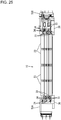
- the holding members 30 that are adjacent in the direction in which the power storage elements 12 are stacked are locked movably in the direction in which the power storage elements 12 are stacked (see FIGS. 25 to 28 ).
- the locking portions 33 for being received by the locking reception portions 34 of the holding member 30 that is disposed below when stacked are formed at the left and right edges of the fifth holding member 30E in FIG. 21 .
- the locking portions 33 for being received by the locking reception portions 34 of the holding member 30 that is disposed below when stacked are formed at the left and right edges of the sixth holding member 30F in FIG. 22 .
- the bus bar holding portions 35 for holding an external connection bus bar 36 that is to be connected to an external device are provided in the first holding member 30A and the fifth holding member 30E.
- the bus bar holding portion 35 includes a recess 35A into which the external connection bus bar 36 is fitted, and a retaining protrusion 35B for retaining the external connection bus bar 36 that has been fitted to the recess 35A.
- the external connection bus bar 36 is made of a metal material such as copper, a copper alloy, aluminum, or an aluminum alloy, and is overlaid on the lead terminal 14. An end of the external connection bus bar 36 protrudes frontward, and the end is provided with a connection hole 36A that is to be connected to an external connection terminal (not shown).
- the first holding member 30A, the second holding member 30B, the third holding member 30C, and the fifth holding member 30E are respectively provided with detection terminal holding portions 37 for holding the voltage detection bus bars 43.
- the detection terminal holding portion 37 is provided with the recess 37A into which the terminal connection portion 43A of the voltage detection bus bar 43 is fitted, as well as an attachment pin 37B for attaching the terminal connection portion 43A and a pair of retaining pieces 37C for retaining the terminal connection portion 43A protruding therefrom.
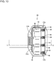
- the voltage detection bus bar 43 is electrically connected to the lead terminal 14 of the power storage element 12 (an example of a connection member). As shown in FIGS. 15 and 16 , the voltage detection bus bar 43 includes a terminal connection portion 43A that is overlaid on and connected to the lead terminal 14, and a connection portion 43B that is bent perpendicularly upward with respect to the terminal connection portion 43A and is electrically connected to a fuse 40.
- the attachment hole 43C into which the attachment pin 37B formed on the holding member 30 is inserted passes through the end of the terminal connection portion 43A of the voltage detection bus bar 43.
- the voltage detection bus bar 43 has the connection portion 43B (an example of a connection portion that is connected to the terminal member) that is disposed in parallel with the direction in which the power storage elements 12 are stacked, and is connected to a first relay terminal 44 (an example of a terminal member).
- the voltage detection bus bar 43 is electrically connected to the fuse 40 via the first relay terminal 44.
- the first relay terminal 44 is made of a metal material such as copper, a copper alloy, aluminum, or an aluminum alloy, for example.
- the first relay terminal 44 includes a tuning fork-shaped terminal portion 44A formed by being branched in two at its end, and a fuse connection portion 44B that rises perpendicularly with respect to the tuning fork-shaped terminal portion 44A.
- connection portion 43B of the voltage detection bus bar 43 is held by the tuning fork-shaped terminal portion 44A of the first relay terminal 44, and the tuning fork-shaped terminal portion 44A is connected to the connection portion 43B.
- the tuning fork-shaped terminal portion 44A of the first relay terminal 44 is connected to the connection portion 43B of the voltage detection bus bar 43 movably in the stacking direction.
- the tuning fork-shaped terminal portion 44A of the first relay terminal 44 is a member for electrically connecting the voltage detection bus bar 43 to the connector 50, and is an example of a terminal member.
- the fuse 40 has a connection portion 40A that is held by the tuning fork-shaped terminal portion 44A of the first relay terminal 44 and is electrically connected thereto, a connection portion 40B that is electrically connected to the fuse connection portion 45A of the second relay terminal 45, and an insulating portion 41 that is provided to connect the two connection portions 40A and 40B and is made of an insulating resin.
- the two connection portions 40A and 40B are connected to each other inside the insulating portion 41.
- the connection portions 40A and 40B are made of a metal material. If an overcurrent flows through the fuse 40, the overcurrent is interrupted by the fuse 40 blowing out.
- the second relay terminal 45 is made of a metal material such as copper, a copper alloy, aluminum, or an aluminum alloy, for example, and includes a fuse connection portion 45A that is connected to the fuse 40, and a tab-shaped male terminal 45B that extends from the fuse connection portion 45A and is disposed inside the terminal accommodation portion 59 of the connector 50.
- the connectors 50 are attached to the front (left side in FIG. 1 ) and the rear (right side in FIG. 1 ) of the electricity storage module 10.
- the connectors 50 are electrically connected to an external device (not shown) such as the voltage detection bus bar 43 (connection member), or a battery control unit.
- the connector 50B attached to the front of the electricity storage module 10 has three terminal accommodation portions 59, whereas the connector 50A attached to the rear has four terminal accommodation portions 59.
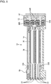
- the connectors 50 are constituted by a first connector 51 that is disposed on the power storage element 12 and a second connector 56 that is fitted to the first connector 51.
- a housing for the first connector 51 is denoted as a first housing 52
- a housing for the second connector 56 is denoted as a second housing 57.
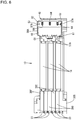
- FIGS. 8 to 11 show the housings 51 and 56 for the connector 50A that is disposed at the rear of the electricity storage module 10.
- the first housing 52 is provided with a fixing portion 53 that protrudes toward the power storage element 12, is overlaid on the through hole 31 of the holding member 30, and into which the fixing member is inserted.
- the fixing portion 53 is penetrated by a circular hole 53A that forms a single hole when overlapped with the through hole 31, and is provided with rectangular fixing holes 53B for receiving fixing protrusions (not shown) that are provided on the first holding member 30A at the lowermost stage and the fifth holding member 30E at the uppermost stage.
- a guide portion 54 for fitting to and guiding the second housing 57 is provided on an inner wall of the first housing 52 on the left side in FIG. 8 .
- a bus bar arrangement portion 55 in which the connection portions 43B of the voltage detection bus bars 43 are disposed is provided inside the first housing 52.
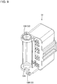
- the second housing 57 has terminal accommodation portions 59 on its right side, and fuse mounting portions 58 on its left side. As shown in FIG. 14 , the terminal accommodation portions 59 and the fuse mounting portions 58 respectively have openings 59A and 58A.
- the second housing 57 includes an accommodation cover 62 for covering the openings 59A of the terminal accommodation portions 59, and a fuse cover 60 for covering the openings 58A of the fuse mounting portions 58.
- Cover locking protrusions 57A for locking the fuse cover 60 protrude from a side wall (a wall on the left side in FIG. 11 ) of the second housing 57. Also, cover locking protrusions 57A for locking the accommodation cover 62 protrude from an upper wall and a lower wall of the second housing 57. Locking holes 61 to which the cover locking protrusions 57A are locked are formed in the fuse cover 60, and locking holes 63 to which the cover locking protrusions 57A are locked and electric wire arrangement holes 64 through which the electric wires 48 are disposed are formed in the accommodation cover 62.
- the male terminal 45B of the second relay terminal 45 is disposed inside the terminal accommodation portion 59 of the second housing 57, a female terminal 47 is fitted to the male terminal 45B, and the male terminal 45B is then disposed inside the terminal accommodation portion 59. Also, as shown in FIG. 14 , a lance 59C for locking the female terminal 47 that is electrically connected to the male terminal 45B is formed on the inner wall of the terminal accommodation portion 59 of the second housing 57.
- the fuse connection portion 45A of the second relay terminal 45 and the fuse connection portion 44B of the first relay terminal 44 are disposed inside the fuse mounting portion 58 of the second housing 57.
- the first relay terminal 44, the fuse 40, and the second relay terminal 45 are connected to each other in the second housing 57.
- the second housing 57 holds the first relay terminal 44 in a state in which the first relay terminal 44 is electrically connected to the voltage detection bus bar 43 while the first relay terminal 44 is allowed to move in the direction in which the power storage elements 12 are stacked (the second housing 57 is an example of a housing).
- the female terminal 47 is held in a state in which the female terminal 47 is retained in the terminal accommodation portion 59 by being locked to the lance 59C formed on the inner wall of the terminal accommodation portion 59.
- the female terminal 47 is obtained by pressing a metal plate material to a predetermined shape.
- the female terminal 47 is connected to an end of the electric wire 48.
- the female terminal 47 includes, at a position opposite to the portion connected to the electric wire 48, a tubular terminal connection portion 47A that is connected to the male terminal 45B of the second relay terminal 45.
- An elastic contact piece 47B that comes into elastic contact with the male terminal 45B is disposed inside the terminal connection portion 47A.
- the fuse 40 and the female terminal 47 are electrically connected to each other via the second relay terminal 45 due to the male terminal 45B and the elastic contact piece 47B coming into elastic contact with each other.
- the electric wire 48 is connected to the female terminal 47 by crimping two sets of barrel portions 47C of the female terminal 47.
- the external connection bus bar 36 is attached to the bus bar holding portion 35, and the voltage detection bus bar 43 is arranged to be held by the detection terminal holding portion 37.
- the terminal connection portion 43A of the voltage detection bus bar 43 is fitted to the recess 37A, the terminal connection portion 43A is retained by the retaining pieces 37C.
- the terminal connection portion 43A of the voltage detection bus bar 43 is attached by the attachment pin 37B, the voltage detection bus bar 43 is fixed to the holding member 30.
- the power storage units 21 are produced by placing the power storage elements 12 on the heat transfer members 22, connecting the external connection bus bars 36 to the lead terminals 14, and connecting the voltage detection bus bar 43 to the lead terminal 14, with a method such as welding or the like.
- a gap is formed between the locking portions 33 and the locking reception portions 34 of the holding members 30 that are adjacent in the stacking direction, and thus the holding members 30 can move in the direction in which the power storage elements 12 are stacked.
- the stacked object 20 is produced by connecting the lead terminals 14 that are adjacent in the stacking direction with a method such as welding after the power storage units 21 are stacked. As a result, the through holes 31 of the holding members 30 overlap with each other to form a single hole.
- the first relay terminal 44 and the second relay terminal 45 are attached to the second housing 57 at the same time as, or before or after a step of producing the stacked object 20.
- the first relay terminal 44 is accommodated in the fuse mounting portion 58 of the second housing 57.
- the fuse connection portion 45A of the second relay terminal 45 is disposed inside the fuse mounting portion 58 of the second housing 57, and the male terminal 45B of the second relay terminal 45 is disposed inside the terminal accommodation portion 59 of the second housing 57.
- connection portion 40A of the fuse 40 is held by the tuning fork-shaped terminal portion 44A of the first relay terminal 44, and the connection portion 40B is connected to the fuse connection portion 45A of the second relay terminal 45.
- the opening 59A of the terminal accommodation portion 59 is covered with the accommodation cover 62 so that the accommodation cover 62 is locked to the second housing 57
- the opening 58A of the fuse mounting portion 58 is covered with the fuse cover 60 so that the fuse cover 60 is locked to the second housing 57
- the second connector 56 is obtained.
- the first housing 52 of the first connector 51 is attached to the stacked object 20.
- the circular hole 53A of the fixing portion 53 overlaps with the through hole 31 of the holding member 30 to form a single hole, and a fixing protrusion of the holding member 30 that is disposed at the uppermost stage and a fixing protrusion of the holding member 30 that is disposed at the lowermost stage are fitted to the fixing hole 53B of the fixing portion 53.
- the connection portion 43B of the voltage detection bus bar 43 is disposed on the bus bar arrangement portion 55 of the first housing 52.
- the tuning fork-shaped terminal portion 44A of the first relay terminal 44 that is disposed inside the second housing 57 is connected to the connection portion 43B of the voltage detection bus bar 43 that is disposed on the bus bar arrangement portion 55 of the first housing 52, movably in the stacking direction.
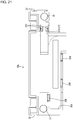
- FIGS. 23 and 24 show a situation in which the tuning fork-shaped terminal portion 44A of the first relay terminal 44 is connected movably in the stacking direction (the vertical direction).
- the first housing 52, the second housing 57, the external connection bus bar, other power storage units 21, and the like are omitted in FIGS. 23 and 24 .
- the tuning fork-shaped terminal portion 44A of the first relay terminal 44 is disposed near the top of the connection portion 43B of the voltage detection bus bar 43, whereas if the power storage element 12 is thin, the tuning fork-shaped terminal portion 44A is disposed near the bottom of the position of the connection portion 43B.
- the tuning fork-shaped terminal portion 44A of the first relay terminal 44 that is shown in FIG. 23 is disposed at a higher position than the position of the tuning fork-shaped terminal portion 44A of the first relay terminal 44 that is shown in FIG. 24 .
- tolerances in the stacking direction are accommodated by movement of the tuning fork-shaped terminal portion 44A of the first relay terminal 44 on the connection portion 43B of the voltage detection bus bar 43 in the direction in which the power storage elements are stacked, and adjusting the connection position.
- FIGS. 25 and 27 show the case where the total thickness of the power storage unit 21 (thickness of the stacked object 20) is maximal
- FIGS. 26 and 28 show the case where the total thickness of the power storage unit 21 (thickness of the stacked object 20) is minimal. As shown in FIGS.
- the voltage detection bus bar 43 is disposed in parallel with the direction in which the power storage elements 12 are stacked, has a connection portion 43B that is connected to the first relay terminal 44, and the first relay terminal 44 is connected to the connection portion 43B in a state in which the first relay terminal 44 can move in the direction in which the power storage elements 12 are stacked, and thus, tolerances in the direction in which the power storage elements 12 are stacked can be accommodated by movement of the first relay terminal 44 in the direction in which the power storage elements 12 are stacked.
- connection portion 43B of the voltage detection bus bar 43 is disposed in parallel with the direction in which the power storage elements 12 are stacked and a configuration in which the first relay terminal 44 is connected to the connection portion 43B movably in the stacking direction, tolerances in the direction in which the power storage elements 12 are stacked can be accommodated. Therefore, tolerances in the direction in which the power storage elements 12 are stacked can be accommodated even with a simple configuration.
- the connectors 50 include the second housing 57 for holding the tuning fork-shaped terminal portion 44A of the first relay terminal 44 in a state in which the tuning fork-shaped terminal portion 44A is electrically connected to the voltage detection bus bar 43 while allowing the movement of the tuning fork-shaped terminal portion 44A in the direction in which the power storage elements 12 are stacked, the first relay terminal 44 is held in the state in which the first relay terminal 44 is electrically connected to the voltage detection bus bar 43 while the first relay terminal 44 is allowed to move in the direction in which the power storage elements 12 are stacked, and therefore, it is possible to ensure the state in which the first relay terminal 44 is electrically connected to the voltage detection bus bar 43.
- the connector 50 is provided with the fuse mounting portion 58 for mounting the fuse 40 that is to be electrically connected to the lead terminal 14, the fuse 40 can be disposed near the power storage element 12, and therefore, overcurrent is unlikely to affect the other power storage elements 12.
- the holding members 30 that are adjacent in the direction in which the power storage elements 12 are stacked are locked movably in the direction in which the power storage elements 12 are stacked, tolerances in the direction in which the power storage elements 12 are stacked can be accommodated.
Applications Claiming Priority (2)
| Application Number | Priority Date | Filing Date | Title |
|---|---|---|---|
| JP2014095693A JP6143108B2 (ja) | 2014-05-07 | 2014-05-07 | 蓄電モジュール |
| PCT/JP2015/062786 WO2015170642A1 (fr) | 2014-05-07 | 2015-04-28 | Module de stockage d'énergie |
Publications (3)
| Publication Number | Publication Date |
|---|---|
| EP3142168A1 true EP3142168A1 (fr) | 2017-03-15 |
| EP3142168A4 EP3142168A4 (fr) | 2017-08-02 |
| EP3142168B1 EP3142168B1 (fr) | 2020-06-17 |
Family
ID=54392494
Family Applications (1)
| Application Number | Title | Priority Date | Filing Date |
|---|---|---|---|
| EP15789377.7A Active EP3142168B1 (fr) | 2014-05-07 | 2015-04-28 | Module de stockage d'énergie |
Country Status (5)
| Country | Link |
|---|---|
| US (1) | US10181592B2 (fr) |
| EP (1) | EP3142168B1 (fr) |
| JP (1) | JP6143108B2 (fr) |
| CN (1) | CN106256031B (fr) |
| WO (1) | WO2015170642A1 (fr) |
Families Citing this family (9)
| Publication number | Priority date | Publication date | Assignee | Title |
|---|---|---|---|---|
| JP6237450B2 (ja) * | 2014-05-07 | 2017-11-29 | 株式会社オートネットワーク技術研究所 | 蓄電モジュール |
| JP2017208481A (ja) * | 2016-05-19 | 2017-11-24 | 株式会社オートネットワーク技術研究所 | 電源装置およびその製造方法 |
| CN107732118A (zh) * | 2016-08-10 | 2018-02-23 | 深圳市沃特玛电池有限公司 | 一种电动汽车底盘结构 |
| JP6571627B2 (ja) * | 2016-11-18 | 2019-09-04 | 矢崎総業株式会社 | 導電モジュール及び電池パック |
| JP6524051B2 (ja) * | 2016-12-09 | 2019-06-05 | 矢崎総業株式会社 | 導体の接続構造および導電モジュール |
| JP6928826B2 (ja) * | 2017-04-12 | 2021-09-01 | パナソニックIpマネジメント株式会社 | 電池モジュールおよび蓄電ユニット |
| JP7145463B2 (ja) * | 2018-07-12 | 2022-10-03 | パナソニックIpマネジメント株式会社 | コンデンサ |
| JP7139997B2 (ja) * | 2019-02-25 | 2022-09-21 | 住友電装株式会社 | 電子モジュール |
| JP7303537B2 (ja) * | 2019-05-16 | 2023-07-05 | 日本圧着端子製造株式会社 | コネクタ連結構造、連結具及びコネクタ |
Family Cites Families (13)
| Publication number | Priority date | Publication date | Assignee | Title |
|---|---|---|---|---|
| KR100556101B1 (ko) * | 2003-12-16 | 2006-03-03 | 주식회사 엘지화학 | 이차전지 모듈 |
| KR100932227B1 (ko) | 2005-09-02 | 2009-12-16 | 주식회사 엘지화학 | 이차전지 및 이를 포함하는 전지모듈 |
| JP5285997B2 (ja) * | 2008-08-27 | 2013-09-11 | 矢崎総業株式会社 | 電源装置 |
| JP5443097B2 (ja) | 2009-08-18 | 2014-03-19 | 矢崎総業株式会社 | 電源装置 |
| WO2011040297A1 (fr) | 2009-10-02 | 2011-04-07 | 株式会社 村田製作所 | Structure d'ensembles de dispositifs de stockage électrique, et structure d'unités de dispositifs de stockage électrique |
| JP2011091003A (ja) | 2009-10-26 | 2011-05-06 | Autonetworks Technologies Ltd | 電池接続アセンブリ |
| JP5508923B2 (ja) * | 2010-04-09 | 2014-06-04 | 日立ビークルエナジー株式会社 | 蓄電モジュール |
| JP5741230B2 (ja) * | 2011-06-09 | 2015-07-01 | 株式会社オートネットワーク技術研究所 | 電池配線モジュール |
| JP5704406B2 (ja) * | 2011-11-30 | 2015-04-22 | 株式会社オートネットワーク技術研究所 | コネクタ及びワイヤーハーネス |
| US8808031B2 (en) * | 2011-12-14 | 2014-08-19 | Tyco Electronics Corporation | Battery connector system |
| JP5584719B2 (ja) * | 2012-03-08 | 2014-09-03 | タイコエレクトロニクスジャパン合同会社 | 電気コネクタおよび燃料電池 |
| JP6237451B2 (ja) * | 2014-02-06 | 2017-11-29 | 株式会社オートネットワーク技術研究所 | 積層コネクタ |
| JP6237450B2 (ja) * | 2014-05-07 | 2017-11-29 | 株式会社オートネットワーク技術研究所 | 蓄電モジュール |
-
2014
- 2014-05-07 JP JP2014095693A patent/JP6143108B2/ja not_active Expired - Fee Related
-
2015
- 2015-04-28 US US15/304,745 patent/US10181592B2/en active Active
- 2015-04-28 EP EP15789377.7A patent/EP3142168B1/fr active Active
- 2015-04-28 WO PCT/JP2015/062786 patent/WO2015170642A1/fr active Application Filing
- 2015-04-28 CN CN201580022677.8A patent/CN106256031B/zh active Active
Also Published As
| Publication number | Publication date |
|---|---|
| EP3142168B1 (fr) | 2020-06-17 |
| JP6143108B2 (ja) | 2017-06-07 |
| US20170040583A1 (en) | 2017-02-09 |
| CN106256031A (zh) | 2016-12-21 |
| JP2015213032A (ja) | 2015-11-26 |
| WO2015170642A1 (fr) | 2015-11-12 |
| US10181592B2 (en) | 2019-01-15 |
| EP3142168A4 (fr) | 2017-08-02 |
| CN106256031B (zh) | 2019-10-15 |
Similar Documents
| Publication | Publication Date | Title |
|---|---|---|
| EP3142168B1 (fr) | Module de stockage d'énergie | |
| EP3211690B1 (fr) | Module de stockage d'énergie | |
| US10950915B2 (en) | Connection module including bus bar extending over groove accomodating connection module-side wires | |
| US10122005B2 (en) | Wiring module and method for producing wiring module | |
| US10490797B2 (en) | Electricity storage module | |
| EP3176850B1 (fr) | Module de stockage d'énergie | |
| CN109037506B (zh) | 电池组 | |
| CN109478629A (zh) | 布线模块 | |
| KR101640100B1 (ko) | 배터리모듈용 직렬연결장치 | |
| US10170805B2 (en) | Electricity storage module | |
| EP3896794B1 (fr) | Connecteur | |
| EP3116046B1 (fr) | Élément de connexion et module de stockage d'électricité | |
| JP6156156B2 (ja) | 配線モジュール | |
| JP2016100211A (ja) | 蓄電モジュール |
Legal Events
| Date | Code | Title | Description |
|---|---|---|---|
| STAA | Information on the status of an ep patent application or granted ep patent |
Free format text: STATUS: THE INTERNATIONAL PUBLICATION HAS BEEN MADE |
|
| PUAI | Public reference made under article 153(3) epc to a published international application that has entered the european phase |
Free format text: ORIGINAL CODE: 0009012 |
|
| STAA | Information on the status of an ep patent application or granted ep patent |
Free format text: STATUS: REQUEST FOR EXAMINATION WAS MADE |
|
| 17P | Request for examination filed |
Effective date: 20161019 |
|
| AK | Designated contracting states |
Kind code of ref document: A1 Designated state(s): AL AT BE BG CH CY CZ DE DK EE ES FI FR GB GR HR HU IE IS IT LI LT LU LV MC MK MT NL NO PL PT RO RS SE SI SK SM TR |
|
| AX | Request for extension of the european patent |
Extension state: BA ME |
|
| A4 | Supplementary search report drawn up and despatched |
Effective date: 20170705 |
|
| RIC1 | Information provided on ipc code assigned before grant |
Ipc: H01G 2/04 20060101ALI20170629BHEP Ipc: H01M 2/10 20060101AFI20170629BHEP Ipc: H01M 10/613 20140101ALI20170629BHEP Ipc: H01M 10/647 20140101ALI20170629BHEP Ipc: H01M 2/20 20060101ALI20170629BHEP Ipc: H01G 11/16 20130101ALI20170629BHEP Ipc: H01G 11/12 20130101ALI20170629BHEP Ipc: H01M 10/48 20060101ALI20170629BHEP Ipc: H01M 2/34 20060101ALI20170629BHEP Ipc: H01M 10/625 20140101ALI20170629BHEP Ipc: H01M 10/6555 20140101ALI20170629BHEP Ipc: H01G 11/76 20130101ALI20170629BHEP |
|
| DAV | Request for validation of the european patent (deleted) | ||
| DAX | Request for extension of the european patent (deleted) | ||
| GRAP | Despatch of communication of intention to grant a patent |
Free format text: ORIGINAL CODE: EPIDOSNIGR1 |
|
| STAA | Information on the status of an ep patent application or granted ep patent |
Free format text: STATUS: GRANT OF PATENT IS INTENDED |
|
| INTG | Intention to grant announced |
Effective date: 20200206 |
|
| GRAS | Grant fee paid |
Free format text: ORIGINAL CODE: EPIDOSNIGR3 |
|
| GRAA | (expected) grant |
Free format text: ORIGINAL CODE: 0009210 |
|
| STAA | Information on the status of an ep patent application or granted ep patent |
Free format text: STATUS: THE PATENT HAS BEEN GRANTED |
|
| AK | Designated contracting states |
Kind code of ref document: B1 Designated state(s): AL AT BE BG CH CY CZ DE DK EE ES FI FR GB GR HR HU IE IS IT LI LT LU LV MC MK MT NL NO PL PT RO RS SE SI SK SM TR |
|
| REG | Reference to a national code |
Ref country code: GB Ref legal event code: FG4D |
|
| REG | Reference to a national code |
Ref country code: CH Ref legal event code: EP |
|
| REG | Reference to a national code |
Ref country code: IE Ref legal event code: FG4D |
|
| REG | Reference to a national code |
Ref country code: DE Ref legal event code: R096 Ref document number: 602015054441 Country of ref document: DE |
|
| REG | Reference to a national code |
Ref country code: AT Ref legal event code: REF Ref document number: 1282421 Country of ref document: AT Kind code of ref document: T Effective date: 20200715 |
|
| PG25 | Lapsed in a contracting state [announced via postgrant information from national office to epo] |
Ref country code: NO Free format text: LAPSE BECAUSE OF FAILURE TO SUBMIT A TRANSLATION OF THE DESCRIPTION OR TO PAY THE FEE WITHIN THE PRESCRIBED TIME-LIMIT Effective date: 20200917 Ref country code: FI Free format text: LAPSE BECAUSE OF FAILURE TO SUBMIT A TRANSLATION OF THE DESCRIPTION OR TO PAY THE FEE WITHIN THE PRESCRIBED TIME-LIMIT Effective date: 20200617 Ref country code: GR Free format text: LAPSE BECAUSE OF FAILURE TO SUBMIT A TRANSLATION OF THE DESCRIPTION OR TO PAY THE FEE WITHIN THE PRESCRIBED TIME-LIMIT Effective date: 20200918 Ref country code: LT Free format text: LAPSE BECAUSE OF FAILURE TO SUBMIT A TRANSLATION OF THE DESCRIPTION OR TO PAY THE FEE WITHIN THE PRESCRIBED TIME-LIMIT Effective date: 20200617 Ref country code: SE Free format text: LAPSE BECAUSE OF FAILURE TO SUBMIT A TRANSLATION OF THE DESCRIPTION OR TO PAY THE FEE WITHIN THE PRESCRIBED TIME-LIMIT Effective date: 20200617 |
|
| REG | Reference to a national code |
Ref country code: LT Ref legal event code: MG4D |
|
| REG | Reference to a national code |
Ref country code: NL Ref legal event code: MP Effective date: 20200617 |
|
| REG | Reference to a national code |
Ref country code: DE Ref legal event code: R079 Ref document number: 602015054441 Country of ref document: DE Free format text: PREVIOUS MAIN CLASS: H01M0002100000 Ipc: H01M0050200000 |
|
| PG25 | Lapsed in a contracting state [announced via postgrant information from national office to epo] |
Ref country code: HR Free format text: LAPSE BECAUSE OF FAILURE TO SUBMIT A TRANSLATION OF THE DESCRIPTION OR TO PAY THE FEE WITHIN THE PRESCRIBED TIME-LIMIT Effective date: 20200617 Ref country code: LV Free format text: LAPSE BECAUSE OF FAILURE TO SUBMIT A TRANSLATION OF THE DESCRIPTION OR TO PAY THE FEE WITHIN THE PRESCRIBED TIME-LIMIT Effective date: 20200617 Ref country code: RS Free format text: LAPSE BECAUSE OF FAILURE TO SUBMIT A TRANSLATION OF THE DESCRIPTION OR TO PAY THE FEE WITHIN THE PRESCRIBED TIME-LIMIT Effective date: 20200617 Ref country code: BG Free format text: LAPSE BECAUSE OF FAILURE TO SUBMIT A TRANSLATION OF THE DESCRIPTION OR TO PAY THE FEE WITHIN THE PRESCRIBED TIME-LIMIT Effective date: 20200917 |
|
| REG | Reference to a national code |
Ref country code: AT Ref legal event code: MK05 Ref document number: 1282421 Country of ref document: AT Kind code of ref document: T Effective date: 20200617 |
|
| PG25 | Lapsed in a contracting state [announced via postgrant information from national office to epo] |
Ref country code: AL Free format text: LAPSE BECAUSE OF FAILURE TO SUBMIT A TRANSLATION OF THE DESCRIPTION OR TO PAY THE FEE WITHIN THE PRESCRIBED TIME-LIMIT Effective date: 20200617 Ref country code: NL Free format text: LAPSE BECAUSE OF FAILURE TO SUBMIT A TRANSLATION OF THE DESCRIPTION OR TO PAY THE FEE WITHIN THE PRESCRIBED TIME-LIMIT Effective date: 20200617 |
|
| PG25 | Lapsed in a contracting state [announced via postgrant information from national office to epo] |
Ref country code: ES Free format text: LAPSE BECAUSE OF FAILURE TO SUBMIT A TRANSLATION OF THE DESCRIPTION OR TO PAY THE FEE WITHIN THE PRESCRIBED TIME-LIMIT Effective date: 20200617 Ref country code: CZ Free format text: LAPSE BECAUSE OF FAILURE TO SUBMIT A TRANSLATION OF THE DESCRIPTION OR TO PAY THE FEE WITHIN THE PRESCRIBED TIME-LIMIT Effective date: 20200617 Ref country code: PT Free format text: LAPSE BECAUSE OF FAILURE TO SUBMIT A TRANSLATION OF THE DESCRIPTION OR TO PAY THE FEE WITHIN THE PRESCRIBED TIME-LIMIT Effective date: 20201019 Ref country code: RO Free format text: LAPSE BECAUSE OF FAILURE TO SUBMIT A TRANSLATION OF THE DESCRIPTION OR TO PAY THE FEE WITHIN THE PRESCRIBED TIME-LIMIT Effective date: 20200617 Ref country code: SM Free format text: LAPSE BECAUSE OF FAILURE TO SUBMIT A TRANSLATION OF THE DESCRIPTION OR TO PAY THE FEE WITHIN THE PRESCRIBED TIME-LIMIT Effective date: 20200617 Ref country code: EE Free format text: LAPSE BECAUSE OF FAILURE TO SUBMIT A TRANSLATION OF THE DESCRIPTION OR TO PAY THE FEE WITHIN THE PRESCRIBED TIME-LIMIT Effective date: 20200617 Ref country code: AT Free format text: LAPSE BECAUSE OF FAILURE TO SUBMIT A TRANSLATION OF THE DESCRIPTION OR TO PAY THE FEE WITHIN THE PRESCRIBED TIME-LIMIT Effective date: 20200617 Ref country code: IT Free format text: LAPSE BECAUSE OF FAILURE TO SUBMIT A TRANSLATION OF THE DESCRIPTION OR TO PAY THE FEE WITHIN THE PRESCRIBED TIME-LIMIT Effective date: 20200617 |
|
| PG25 | Lapsed in a contracting state [announced via postgrant information from national office to epo] |
Ref country code: PL Free format text: LAPSE BECAUSE OF FAILURE TO SUBMIT A TRANSLATION OF THE DESCRIPTION OR TO PAY THE FEE WITHIN THE PRESCRIBED TIME-LIMIT Effective date: 20200617 Ref country code: SK Free format text: LAPSE BECAUSE OF FAILURE TO SUBMIT A TRANSLATION OF THE DESCRIPTION OR TO PAY THE FEE WITHIN THE PRESCRIBED TIME-LIMIT Effective date: 20200617 Ref country code: IS Free format text: LAPSE BECAUSE OF FAILURE TO SUBMIT A TRANSLATION OF THE DESCRIPTION OR TO PAY THE FEE WITHIN THE PRESCRIBED TIME-LIMIT Effective date: 20201017 |
|
| REG | Reference to a national code |
Ref country code: DE Ref legal event code: R097 Ref document number: 602015054441 Country of ref document: DE |
|
| PLBE | No opposition filed within time limit |
Free format text: ORIGINAL CODE: 0009261 |
|
| STAA | Information on the status of an ep patent application or granted ep patent |
Free format text: STATUS: NO OPPOSITION FILED WITHIN TIME LIMIT |
|
| PG25 | Lapsed in a contracting state [announced via postgrant information from national office to epo] |
Ref country code: DK Free format text: LAPSE BECAUSE OF FAILURE TO SUBMIT A TRANSLATION OF THE DESCRIPTION OR TO PAY THE FEE WITHIN THE PRESCRIBED TIME-LIMIT Effective date: 20200617 |
|
| 26N | No opposition filed |
Effective date: 20210318 |
|
| PG25 | Lapsed in a contracting state [announced via postgrant information from national office to epo] |
Ref country code: SI Free format text: LAPSE BECAUSE OF FAILURE TO SUBMIT A TRANSLATION OF THE DESCRIPTION OR TO PAY THE FEE WITHIN THE PRESCRIBED TIME-LIMIT Effective date: 20200617 |
|
| PG25 | Lapsed in a contracting state [announced via postgrant information from national office to epo] |
Ref country code: MC Free format text: LAPSE BECAUSE OF FAILURE TO SUBMIT A TRANSLATION OF THE DESCRIPTION OR TO PAY THE FEE WITHIN THE PRESCRIBED TIME-LIMIT Effective date: 20200617 |
|
| GBPC | Gb: european patent ceased through non-payment of renewal fee |
Effective date: 20210428 |
|
| PG25 | Lapsed in a contracting state [announced via postgrant information from national office to epo] |
Ref country code: LU Free format text: LAPSE BECAUSE OF NON-PAYMENT OF DUE FEES Effective date: 20210428 |
|
| REG | Reference to a national code |
Ref country code: BE Ref legal event code: MM Effective date: 20210430 |
|
| PG25 | Lapsed in a contracting state [announced via postgrant information from national office to epo] |
Ref country code: GB Free format text: LAPSE BECAUSE OF NON-PAYMENT OF DUE FEES Effective date: 20210428 Ref country code: FR Free format text: LAPSE BECAUSE OF NON-PAYMENT OF DUE FEES Effective date: 20210430 Ref country code: CH Free format text: LAPSE BECAUSE OF NON-PAYMENT OF DUE FEES Effective date: 20210430 Ref country code: LI Free format text: LAPSE BECAUSE OF NON-PAYMENT OF DUE FEES Effective date: 20210430 |
|
| PG25 | Lapsed in a contracting state [announced via postgrant information from national office to epo] |
Ref country code: IE Free format text: LAPSE BECAUSE OF NON-PAYMENT OF DUE FEES Effective date: 20210428 |
|
| PG25 | Lapsed in a contracting state [announced via postgrant information from national office to epo] |
Ref country code: IS Free format text: LAPSE BECAUSE OF FAILURE TO SUBMIT A TRANSLATION OF THE DESCRIPTION OR TO PAY THE FEE WITHIN THE PRESCRIBED TIME-LIMIT Effective date: 20201017 |
|
| PG25 | Lapsed in a contracting state [announced via postgrant information from national office to epo] |
Ref country code: BE Free format text: LAPSE BECAUSE OF NON-PAYMENT OF DUE FEES Effective date: 20210430 |
|
| PGFP | Annual fee paid to national office [announced via postgrant information from national office to epo] |
Ref country code: DE Payment date: 20220302 Year of fee payment: 8 |
|
| PG25 | Lapsed in a contracting state [announced via postgrant information from national office to epo] |
Ref country code: HU Free format text: LAPSE BECAUSE OF FAILURE TO SUBMIT A TRANSLATION OF THE DESCRIPTION OR TO PAY THE FEE WITHIN THE PRESCRIBED TIME-LIMIT; INVALID AB INITIO Effective date: 20150428 |
|
| PG25 | Lapsed in a contracting state [announced via postgrant information from national office to epo] |
Ref country code: CY Free format text: LAPSE BECAUSE OF FAILURE TO SUBMIT A TRANSLATION OF THE DESCRIPTION OR TO PAY THE FEE WITHIN THE PRESCRIBED TIME-LIMIT Effective date: 20200617 |
|
| REG | Reference to a national code |
Ref country code: DE Ref legal event code: R119 Ref document number: 602015054441 Country of ref document: DE |
|
| PG25 | Lapsed in a contracting state [announced via postgrant information from national office to epo] |
Ref country code: DE Free format text: LAPSE BECAUSE OF NON-PAYMENT OF DUE FEES Effective date: 20231103 |