EP3141721B1 - Reflektierendes isolationssystem - Google Patents
Reflektierendes isolationssystem Download PDFInfo
- Publication number
- EP3141721B1 EP3141721B1 EP15184579.9A EP15184579A EP3141721B1 EP 3141721 B1 EP3141721 B1 EP 3141721B1 EP 15184579 A EP15184579 A EP 15184579A EP 3141721 B1 EP3141721 B1 EP 3141721B1
- Authority
- EP
- European Patent Office
- Prior art keywords
- exhaust gas
- insulation
- insulated
- gas component
- molded part
- Prior art date
- Legal status (The legal status is an assumption and is not a legal conclusion. Google has not performed a legal analysis and makes no representation as to the accuracy of the status listed.)
- Active
Links
- 238000009413 insulation Methods 0.000 title claims description 78
- 239000000835 fiber Substances 0.000 claims description 69
- 238000007373 indentation Methods 0.000 claims description 21
- 238000000034 method Methods 0.000 claims description 18
- 239000000049 pigment Substances 0.000 claims description 14
- 239000004033 plastic Substances 0.000 claims description 6
- 229920003023 plastic Polymers 0.000 claims description 6
- 229920001169 thermoplastic Polymers 0.000 claims description 4
- 238000005253 cladding Methods 0.000 claims 7
- 230000003584 silencer Effects 0.000 claims 1
- 238000000465 moulding Methods 0.000 description 28
- 230000005855 radiation Effects 0.000 description 13
- 230000008901 benefit Effects 0.000 description 12
- 238000002955 isolation Methods 0.000 description 11
- 239000011810 insulating material Substances 0.000 description 8
- 238000010521 absorption reaction Methods 0.000 description 7
- 238000011161 development Methods 0.000 description 6
- 238000004134 energy conservation Methods 0.000 description 5
- 230000036961 partial effect Effects 0.000 description 4
- 239000000126 substance Substances 0.000 description 4
- VYZAMTAEIAYCRO-UHFFFAOYSA-N Chromium Chemical compound [Cr] VYZAMTAEIAYCRO-UHFFFAOYSA-N 0.000 description 3
- RTAQQCXQSZGOHL-UHFFFAOYSA-N Titanium Chemical compound [Ti] RTAQQCXQSZGOHL-UHFFFAOYSA-N 0.000 description 3
- 229910052787 antimony Inorganic materials 0.000 description 3
- WATWJIUSRGPENY-UHFFFAOYSA-N antimony atom Chemical compound [Sb] WATWJIUSRGPENY-UHFFFAOYSA-N 0.000 description 3
- 230000037237 body shape Effects 0.000 description 3
- 229910052804 chromium Inorganic materials 0.000 description 3
- 239000011651 chromium Substances 0.000 description 3
- 238000002485 combustion reaction Methods 0.000 description 3
- 238000005516 engineering process Methods 0.000 description 3
- 239000012774 insulation material Substances 0.000 description 3
- 239000000463 material Substances 0.000 description 3
- 230000007246 mechanism Effects 0.000 description 3
- 229910052751 metal Inorganic materials 0.000 description 3
- 239000002184 metal Substances 0.000 description 3
- 239000002245 particle Substances 0.000 description 3
- 230000002829 reductive effect Effects 0.000 description 3
- 229920001187 thermosetting polymer Polymers 0.000 description 3
- 239000010936 titanium Substances 0.000 description 3
- 229910052719 titanium Inorganic materials 0.000 description 3
- GWEVSGVZZGPLCZ-UHFFFAOYSA-N titanium dioxide Inorganic materials O=[Ti]=O GWEVSGVZZGPLCZ-UHFFFAOYSA-N 0.000 description 3
- 238000012546 transfer Methods 0.000 description 3
- 230000008859 change Effects 0.000 description 2
- 238000001816 cooling Methods 0.000 description 2
- 238000013461 design Methods 0.000 description 2
- 230000000694 effects Effects 0.000 description 2
- 239000002657 fibrous material Substances 0.000 description 2
- 239000000945 filler Substances 0.000 description 2
- 239000012530 fluid Substances 0.000 description 2
- 238000004519 manufacturing process Methods 0.000 description 2
- 238000005498 polishing Methods 0.000 description 2
- 229920006395 saturated elastomer Polymers 0.000 description 2
- 230000003068 static effect Effects 0.000 description 2
- 230000035882 stress Effects 0.000 description 2
- 239000004416 thermosoftening plastic Substances 0.000 description 2
- BPQQTUXANYXVAA-UHFFFAOYSA-N Orthosilicate Chemical compound [O-][Si]([O-])([O-])[O-] BPQQTUXANYXVAA-UHFFFAOYSA-N 0.000 description 1
- 230000009471 action Effects 0.000 description 1
- 239000011230 binding agent Substances 0.000 description 1
- 239000000919 ceramic Substances 0.000 description 1
- 239000011248 coating agent Substances 0.000 description 1
- 238000000576 coating method Methods 0.000 description 1
- 238000010276 construction Methods 0.000 description 1
- 239000007799 cork Substances 0.000 description 1
- 230000001419 dependent effect Effects 0.000 description 1
- 238000009792 diffusion process Methods 0.000 description 1
- 230000005670 electromagnetic radiation Effects 0.000 description 1
- 239000004744 fabric Substances 0.000 description 1
- 230000006870 function Effects 0.000 description 1
- 239000003365 glass fiber Substances 0.000 description 1
- 230000017525 heat dissipation Effects 0.000 description 1
- 230000008642 heat stress Effects 0.000 description 1
- 238000010438 heat treatment Methods 0.000 description 1
- 239000011796 hollow space material Substances 0.000 description 1
- 238000012423 maintenance Methods 0.000 description 1
- 235000012054 meals Nutrition 0.000 description 1
- 238000010606 normalization Methods 0.000 description 1
- 239000003415 peat Substances 0.000 description 1
- 210000002381 plasma Anatomy 0.000 description 1
- 238000012545 processing Methods 0.000 description 1
- 230000001681 protective effect Effects 0.000 description 1
- 230000009993 protective function Effects 0.000 description 1
- 230000000284 resting effect Effects 0.000 description 1
- 230000000717 retained effect Effects 0.000 description 1
- 230000002441 reversible effect Effects 0.000 description 1
- 239000007787 solid Substances 0.000 description 1
- 229910001220 stainless steel Inorganic materials 0.000 description 1
- 239000010935 stainless steel Substances 0.000 description 1
- 230000031068 symbiosis, encompassing mutualism through parasitism Effects 0.000 description 1
- 230000008646 thermal stress Effects 0.000 description 1
- 239000012815 thermoplastic material Substances 0.000 description 1
Images

Classifications
-
- F—MECHANICAL ENGINEERING; LIGHTING; HEATING; WEAPONS; BLASTING
- F01—MACHINES OR ENGINES IN GENERAL; ENGINE PLANTS IN GENERAL; STEAM ENGINES
- F01N—GAS-FLOW SILENCERS OR EXHAUST APPARATUS FOR MACHINES OR ENGINES IN GENERAL; GAS-FLOW SILENCERS OR EXHAUST APPARATUS FOR INTERNAL COMBUSTION ENGINES
- F01N13/00—Exhaust or silencing apparatus characterised by constructional features ; Exhaust or silencing apparatus, or parts thereof, having pertinent characteristics not provided for in, or of interest apart from, groups F01N1/00 - F01N5/00, F01N9/00, F01N11/00
- F01N13/08—Other arrangements or adaptations of exhaust conduits
- F01N13/10—Other arrangements or adaptations of exhaust conduits of exhaust manifolds
- F01N13/102—Other arrangements or adaptations of exhaust conduits of exhaust manifolds having thermal insulation
-
- F—MECHANICAL ENGINEERING; LIGHTING; HEATING; WEAPONS; BLASTING
- F01—MACHINES OR ENGINES IN GENERAL; ENGINE PLANTS IN GENERAL; STEAM ENGINES
- F01N—GAS-FLOW SILENCERS OR EXHAUST APPARATUS FOR MACHINES OR ENGINES IN GENERAL; GAS-FLOW SILENCERS OR EXHAUST APPARATUS FOR INTERNAL COMBUSTION ENGINES
- F01N1/00—Silencing apparatus characterised by method of silencing
- F01N1/24—Silencing apparatus characterised by method of silencing by using sound-absorbing materials
-
- F—MECHANICAL ENGINEERING; LIGHTING; HEATING; WEAPONS; BLASTING
- F01—MACHINES OR ENGINES IN GENERAL; ENGINE PLANTS IN GENERAL; STEAM ENGINES
- F01N—GAS-FLOW SILENCERS OR EXHAUST APPARATUS FOR MACHINES OR ENGINES IN GENERAL; GAS-FLOW SILENCERS OR EXHAUST APPARATUS FOR INTERNAL COMBUSTION ENGINES
- F01N13/00—Exhaust or silencing apparatus characterised by constructional features ; Exhaust or silencing apparatus, or parts thereof, having pertinent characteristics not provided for in, or of interest apart from, groups F01N1/00 - F01N5/00, F01N9/00, F01N11/00
- F01N13/14—Exhaust or silencing apparatus characterised by constructional features ; Exhaust or silencing apparatus, or parts thereof, having pertinent characteristics not provided for in, or of interest apart from, groups F01N1/00 - F01N5/00, F01N9/00, F01N11/00 having thermal insulation
- F01N13/141—Double-walled exhaust pipes or housings
- F01N13/143—Double-walled exhaust pipes or housings with air filling the space between both walls
-
- B—PERFORMING OPERATIONS; TRANSPORTING
- B32—LAYERED PRODUCTS
- B32B—LAYERED PRODUCTS, i.e. PRODUCTS BUILT-UP OF STRATA OF FLAT OR NON-FLAT, e.g. CELLULAR OR HONEYCOMB, FORM
- B32B15/00—Layered products comprising a layer of metal
- B32B15/04—Layered products comprising a layer of metal comprising metal as the main or only constituent of a layer, which is next to another layer of the same or of a different material
- B32B15/08—Layered products comprising a layer of metal comprising metal as the main or only constituent of a layer, which is next to another layer of the same or of a different material of synthetic resin
-
- B—PERFORMING OPERATIONS; TRANSPORTING
- B32—LAYERED PRODUCTS
- B32B—LAYERED PRODUCTS, i.e. PRODUCTS BUILT-UP OF STRATA OF FLAT OR NON-FLAT, e.g. CELLULAR OR HONEYCOMB, FORM
- B32B15/00—Layered products comprising a layer of metal
- B32B15/18—Layered products comprising a layer of metal comprising iron or steel
-
- F—MECHANICAL ENGINEERING; LIGHTING; HEATING; WEAPONS; BLASTING
- F01—MACHINES OR ENGINES IN GENERAL; ENGINE PLANTS IN GENERAL; STEAM ENGINES
- F01N—GAS-FLOW SILENCERS OR EXHAUST APPARATUS FOR MACHINES OR ENGINES IN GENERAL; GAS-FLOW SILENCERS OR EXHAUST APPARATUS FOR INTERNAL COMBUSTION ENGINES
- F01N13/00—Exhaust or silencing apparatus characterised by constructional features ; Exhaust or silencing apparatus, or parts thereof, having pertinent characteristics not provided for in, or of interest apart from, groups F01N1/00 - F01N5/00, F01N9/00, F01N11/00
- F01N13/14—Exhaust or silencing apparatus characterised by constructional features ; Exhaust or silencing apparatus, or parts thereof, having pertinent characteristics not provided for in, or of interest apart from, groups F01N1/00 - F01N5/00, F01N9/00, F01N11/00 having thermal insulation
- F01N13/148—Multiple layers of insulating material
-
- B—PERFORMING OPERATIONS; TRANSPORTING
- B32—LAYERED PRODUCTS
- B32B—LAYERED PRODUCTS, i.e. PRODUCTS BUILT-UP OF STRATA OF FLAT OR NON-FLAT, e.g. CELLULAR OR HONEYCOMB, FORM
- B32B2255/00—Coating on the layer surface
- B32B2255/10—Coating on the layer surface on synthetic resin layer or on natural or synthetic rubber layer
-
- B—PERFORMING OPERATIONS; TRANSPORTING
- B32—LAYERED PRODUCTS
- B32B—LAYERED PRODUCTS, i.e. PRODUCTS BUILT-UP OF STRATA OF FLAT OR NON-FLAT, e.g. CELLULAR OR HONEYCOMB, FORM
- B32B2307/00—Properties of the layers or laminate
- B32B2307/10—Properties of the layers or laminate having particular acoustical properties
- B32B2307/102—Insulating
-
- B—PERFORMING OPERATIONS; TRANSPORTING
- B32—LAYERED PRODUCTS
- B32B—LAYERED PRODUCTS, i.e. PRODUCTS BUILT-UP OF STRATA OF FLAT OR NON-FLAT, e.g. CELLULAR OR HONEYCOMB, FORM
- B32B2307/00—Properties of the layers or laminate
- B32B2307/30—Properties of the layers or laminate having particular thermal properties
- B32B2307/304—Insulating
-
- B—PERFORMING OPERATIONS; TRANSPORTING
- B32—LAYERED PRODUCTS
- B32B—LAYERED PRODUCTS, i.e. PRODUCTS BUILT-UP OF STRATA OF FLAT OR NON-FLAT, e.g. CELLULAR OR HONEYCOMB, FORM
- B32B2307/00—Properties of the layers or laminate
- B32B2307/40—Properties of the layers or laminate having particular optical properties
- B32B2307/416—Reflective
-
- F—MECHANICAL ENGINEERING; LIGHTING; HEATING; WEAPONS; BLASTING
- F01—MACHINES OR ENGINES IN GENERAL; ENGINE PLANTS IN GENERAL; STEAM ENGINES
- F01N—GAS-FLOW SILENCERS OR EXHAUST APPARATUS FOR MACHINES OR ENGINES IN GENERAL; GAS-FLOW SILENCERS OR EXHAUST APPARATUS FOR INTERNAL COMBUSTION ENGINES
- F01N2260/00—Exhaust treating devices having provisions not otherwise provided for
- F01N2260/20—Exhaust treating devices having provisions not otherwise provided for for heat or sound protection, e.g. using a shield or specially shaped outer surface of exhaust device
-
- F—MECHANICAL ENGINEERING; LIGHTING; HEATING; WEAPONS; BLASTING
- F01—MACHINES OR ENGINES IN GENERAL; ENGINE PLANTS IN GENERAL; STEAM ENGINES
- F01N—GAS-FLOW SILENCERS OR EXHAUST APPARATUS FOR MACHINES OR ENGINES IN GENERAL; GAS-FLOW SILENCERS OR EXHAUST APPARATUS FOR INTERNAL COMBUSTION ENGINES
- F01N2310/00—Selection of sound absorbing or insulating material
- F01N2310/02—Mineral wool, e.g. glass wool, rock wool, asbestos or the like
-
- F—MECHANICAL ENGINEERING; LIGHTING; HEATING; WEAPONS; BLASTING
- F01—MACHINES OR ENGINES IN GENERAL; ENGINE PLANTS IN GENERAL; STEAM ENGINES
- F01N—GAS-FLOW SILENCERS OR EXHAUST APPARATUS FOR MACHINES OR ENGINES IN GENERAL; GAS-FLOW SILENCERS OR EXHAUST APPARATUS FOR INTERNAL COMBUSTION ENGINES
- F01N2510/00—Surface coverings
- F01N2510/02—Surface coverings for thermal insulation
-
- F—MECHANICAL ENGINEERING; LIGHTING; HEATING; WEAPONS; BLASTING
- F01—MACHINES OR ENGINES IN GENERAL; ENGINE PLANTS IN GENERAL; STEAM ENGINES
- F01N—GAS-FLOW SILENCERS OR EXHAUST APPARATUS FOR MACHINES OR ENGINES IN GENERAL; GAS-FLOW SILENCERS OR EXHAUST APPARATUS FOR INTERNAL COMBUSTION ENGINES
- F01N2530/00—Selection of materials for tubes, chambers or housings
- F01N2530/18—Plastics material, e.g. polyester resin
- F01N2530/20—Plastics material, e.g. polyester resin reinforced with mineral or metallic fibres
Definitions
- the invention relates to an insulation system for thermo-acoustic insulation of an exhaust gas component to be isolated, as well as a corresponding method for the isolation of such an exhaust gas component.
- the specific heat capacity c also called specific heat, results from the normalization of the heat capacity C to the mass of the substance.
- thermal insulation for example in exhaust systems of vehicles, are basically three mechanisms to consider, the heat conduction, heat radiation and convection.
- thermal radiation electromagnetic radiation is emitted by a solid, fluids or plasmas.
- the emitted radiation power P is proportional to the fourth power of the temperature of the radiating body, ie P ⁇ T 4 (Stefan Boltzmann law).
- thermal radiation is the only way to transfer heat energy.
- Convection or heat transfer is another mechanism for heat transport.
- Convection is caused by a flow that carries particles.
- a flowing fluid may absorb or release heat from a surface.
- One cause of the transporting flow may be temperature differences.
- the particle transport is caused by external action, for example a blower or a pump.
- free convection the particle transport is caused by a temperature gradient within the medium.
- the DE 10 2010 0660071 A1 discloses a part of an exhaust system for an internal combustion engine having an exhaust gas-carrying device and an insulation for this device and a sensor device mounted in the region of the insulation in the device, wherein the sensor device has a fixedly connected to an outer wall of the device nozzle and a sensor held in this nozzle ,
- the US 2009/197044 A1 discloses a heat shield which additionally has sound absorbing properties.
- the US 2010/035078 A1 discloses a hand windable heat shield and corresponding construction method wherein outer and inner layers are of metal and valleys and corresponding peaks are embossed into the metal.
- the EP 2 444 617 A1 discloses an exhaust manifold for an internal combustion engine having an exhaust gas carrying inner tube and an outer shell, wherein the insulation is formed as a molded insulating molded part and disposed between the shell and the inner space, the insulating molded part including an insulating fiber fabric and a binder.
- the EP2 444 616 A1 discloses a hot gas-conducting component, in particular for an exhaust system of an internal combustion engine, wherein on the component an insulation is arranged, the heat-reflecting and / or heat-absorbing pigments are added.
- the AT 133 379 B discloses an insulating mat consisting of smooth and corrugated cardboard plies, wherein a corrugated cardboard ply is applied to a smooth cardboard ply which is coated with cork meal, peat or similar heat-insulating materials.
- a first example is air gap isolation without convection.
- the air gap insulation without convection is a self-contained insulation system in which essentially static air is used as insulation material.
- An advantage of this type of insulation is the low specific heat capacity of the air. Thus, only a small amount of heat can be absorbed by the system.
- heat-saturated insulating material that is, heat-saturated air
- the heat loss due to heat conduction is kept very small.
- a disadvantage of this method is the heat radiation, which can affect the surrounding components. Furthermore, only a very small temperature difference beyond the Dämmzone is possible.
- the surface temperature of the insulation system ie the air
- the application temperature ie the temperature of the system to be insulated
- the air gap insulation without convection can be said to provide very good energy conservation in the system to be insulated, but it does not guarantee sufficient protection for surrounding components due to the high surface temperatures.
- the environment is hardly protected from acoustic emissions.
- a third example of insulating systems are those in which the insulating material is a filler between the system to be insulated and the metallic outer shell.
- these are usually glass fibers, for example silicate fibers or ceramic fibers, which are applied directly to systems to be insulated. This is currently one of the most used methods in the automotive sector.
- This isolation method offers the interim solution to the first two. Advantages are the low surface temperatures in a small space and a good acoustic absorption by the fiber material. In terms of energy conservation in the system to be isolated, it is an interim solution. There is no noticeable convection, which makes it better suited for energy conservation than heat shield insulation.
- this system provides a much larger amount of heat to be absorbed than the air gap insulation without convection, which in this case means a reduced energy conservation.
- Another disadvantage in terms of energy conservation is the lack of radiation reflection, due to the direct application which allows only heat conduction.
- this isolation system is the middle ground between the first two systems and accordingly represents one of the most frequently used methods.
- the invention provides: an insulation system for thermoacoustic insulation of an exhaust gas component to be insulated, comprising a fiber molded part with a surface facing away from the exhaust gas component to be insulated, wherein the opposite surface is at least partially covered with a sheath, and with an insulating surface, the insulating Faces exhaust gas component, wherein the fiber molded part is applied to the exhaust gas component to be insulated such that form a plurality of closed cavities between a part of the insulating surface of the fiber molding and the exhaust gas component to be isolated, wherein a predefined portion of the insulating surface of the fiber molded part contacts the exhaust gas component to be isolated, wherein the predefined proportion is a minimum of 10% and a maximum of 90%, in particular a minimum of 25% to a maximum of 55%; wherein the insulating surface facing the exhaust gas component to be insulated has a plurality of predefined indentations.
- a cavity should be understood as a closed system, a chamber.
- This system ie the cavity, is limited by the insulating surface of the fiber molded part on the one hand and the surface of the exhaust gas component to be insulated or the areas of this exhaust gas component to be isolated and thus completed.
- the cavity offers the advantage of enclosing air.
- the cavity thus acts as an air reservoir. This results in a low amount of heat to be absorbed by the insulation system due to equation (3), because the trapped air has only a small mass. Because the cavity is closed, there is virtually no noticeable convection.
- the insulation system ie the cavity, more precisely the air in the cavity, with a small amount of heat remains almost the entire heat energy in the system to be isolated.
- the contact surfaces Only at the contact surfaces can take place an additional heat absorption. However, since the contact surfaces are small and limited, there is only a minimal increase in heat absorption across the contact surface.
- the thermal conductivity the advantage here is that air, in particular static air, represents a medium with a very low thermal conductivity. Unlike the air gap insulation without convection arises from the still lying above the cavity fiber molding, which includes, for example, an insulating fiber. This can in particular provide for low surface temperatures. Thus remains Almost all of the heat energy in the system to be insulated is obtained and the surrounding components are optimally protected because the surface temperatures remain relatively low.
- the fiber molding so the insulation material has a somewhat higher but low thermal conductivity compared to the air in the cavity.
- the contact surface of the fiber molding with the system to be insulated can be kept low, namely, for example, only 10%. Below 10% problems with instabilities can arise.
- a typical value in the sense of an upper limit can be about 90% of the insulating surface, above 90%, the advantages disappear visibly compared to a completely contacted insulating surface.
- other values are also possible, in particular a value between a minimum of 25% and a maximum of 55% is possible.
- a kind of symbiosis results from a reduced thermal conductivity of the system.
- the possibility of achieving low surface temperatures results from the insulating fiber of the fiber molded part which is still above the hollow space.
- virtually all the heat energy is retained in the system to be insulated and the surrounding components are well protected due to the low surface temperatures.
- the insulating surface of the fiber molding may be coated with color pigments having a TSR, Total Solar Reflectance, value of at least 65%, wherein the proportion of the color pigments based on the total mass of the fiber molding is between 1 - 5%, preferably between 1 , 5 - 3%.
- the back reflection of the thermal radiation can be additionally increased. This can be considered as a greenhouse effect caused artificially in the cavities.
- the emitted thermal radiation of the system to be insulated, such as the exhaust gas component to be isolated is reflected by the treated surface of the fiber molding and largely recycled to the system to be isolated.
- the absorbed part of the radiation in turn contributes to the heat saturation of the insulation system.
- the color pigments may comprise a chromium / antimony / titanium-based polishing rutile.
- an inner liner which is preferably a metallic inner liner.
- a metallic inner liner be used. This has the advantage that a de- and remontability of the fiber molding can be provided as simple as possible. In addition, the fiber molding, so in particular the fiber material can be protected.
- the sheath may comprise a metallic sheath or a thermosetting thermoplastic or an elastomeric plastic.
- these plastics are also characterized by good acoustic properties with regard to sound insulation. from. In design with matching metallic sheath, this can typically be provided so that the outer sheath is to close or open. Thus, there is the possibility of a variable opening or closing of the outer shell, so the sheath. This gives the system the ability to quickly come to operating temperature according to the exhaust system with the case closed and to cause cooling of the component by convection when the variant is open, ie selectively connect or disconnect convection.
- the plurality of predefined indentations can be hemispherical and / or semi-cylindrical indentations, so that the cavities can be formed hemispherical and / or semicylindrical.
- the indentations can be understood as air chambers, ie filled with air cavities, with the above advantages apply to each of the cavities.
- Semi-cylindrical indentations have the advantage that they can be realized in a particularly simple manner in terms of production technology / tool technology and in this case have the advantageous properties of the insulation system. It is understood that other body or partial body shapes can be selected so that one or more cavities can be formed.
- the invention further provides an exhaust gas component having an insulation disposed at least partially on the component, wherein the insulation is formed as an insulation system as described above.
- the invention provides a muffler comprising at least one exhaust gas component as described above.
- the invention provides a method for thermoacoustically isolating an exhaust gas component, the method comprising the steps of: providing a fiber molded part with a surface facing away from the exhaust gas component to be insulated, the opposite surface is at least partially covered with a sheath, and with an insulating surface, which faces the exhaust gas component; Applying the fiber molding on the exhaust gas component such that forms a plurality of closed cavities between a part of the insulating surface of the fiber molding and the exhaust gas component to be isolated; wherein a predefined proportion of the insulating surface of the fiber molded part contacts the exhaust gas component to be insulated, the predefined proportion being a minimum of 10% and a maximum of 90%, in particular a minimum of 25% to a maximum of 55%; wherein the insulating surface facing the exhaust gas component to be insulated has a plurality of predefined indentations.
- the insulating surface of the fiber molding may be coated with color pigments having a TSR, Total Solar Reflectance, value of at least 65%, wherein the proportion of the color pigments based on the total mass of the fiber molding is between 1 - 5%, preferably between 1 , 5 - 3%.
- the color pigments may comprise a chromium / antimony / titanium-based polishing rutile.
- an inner liner which is preferably a metallic inner liner.
- the fiber molded part may further comprise a surface facing away from the exhaust gas component to be insulated, wherein the opposite surface is at least partially covered with a sheath, wherein the sheath may be a metallic sheath or may comprise a thermosetting thermoplastic or elastomeric plastic.
- the plurality of predefined indentations may be hemispherical or semi-cylindrical in shape.
- An example of an application of the described isolation system and the corresponding method is the automotive sector. It is important, for example, the strict Comply with European standards, according to which exhaust gas energy and temperature must be kept at an ever higher level to the downstream units in the exhaust system such. As DPF, Oxikat, SCR system, etc. to operate optimally and reduce emissions.
- the general aim is to minimize energy losses of the system to be isolated by releasing energy in the form of thermal energy, ie heat conduction, heat radiation, convection, and also in the form of acoustic energy, ie sound, as low as possible.
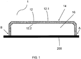
- Fig. 1 shows a schematic view of an insulation system 1 for thermo-acoustic insulation of a component 200 to be isolated.
- the component to be isolated 200 may be, for example, an exhaust gas component.
- the insulation system 1 in Fig. 1 comprises a fiber molding 12, which comprises an insulating material, such as fibers or non-woven.
- the fiber molded part 12 has one of the component 200 to be insulated facing away from side or surface, which is designated by the reference numeral 12.1.
- This area 12.1 is in Fig. 1 with a Sheath 14 sheathed. In the schematic representation in Fig. 1 the sheath 14 is practically on the surface 12.1.
- the fiber molded part 12 further has one of the component to be insulated facing side or surface 12.2.
- the surface 12.2 is an insulating surface.
- Fig. 1 shows a greatly simplified sectional drawing.
- a component 200 to be insulated is insulated by an insulation system 1 with a fiber molded part 12.
- the fiber molded part 12 is applied to the component 200 to be insulated in such a way that it applies the component 200 to be insulated only with a part of the insulating surface 12. 2.
- the contact takes place through the insulating surface 12.2 such that a cavity 16 is formed.
- the cavity 16 can also be understood as a chamber.
- the cavity 16 is completely enclosed or bounded by the insulating surface 12. 2 and the component 200 to be insulated, ie formed between these elements.
- the cavity 16 is typically filled with air and may also be considered as an air reservoir. It is understood that a plurality of cavities of similar nature can be formed and that Fig. 1 showing only one cavity.
- the cavity 16 may include air. Air in turn has a low heat capacity and can therefore absorb only a small amount of heat of the system to be insulated due to equation (3). There is virtually no convection in the cavity 16 instead. Thus, almost all of the heat energy remains in the system 200 to be isolated.
- the insulating surface 12.2 contacts the component 200 only in the region of the points A and B. It is therefore a predefined portion of the insulating surface 12.2 of the fiber molded part in the region A and B, where the component 200 to be insulated is contacted by the insulating surface 12.2.
- the predefined fraction may typically be at least 10%.
- a typical value in the sense of an upper limit can amount to 90% of the insulating surface. Other values may also be possible. Below 10%, there may be problems with instabilities. Above 90%, the advantages visibly disappear over a completely contacted insulating surface. However, other values are also possible, in particular a value between a minimum of 25% and a maximum of 55% is possible.
- the entire fiber molded part 12 comprises insulating material.
- the cavity 16 is additionally enclosed in the region of the fiber molded part 12 by insulating material.
- This insulating material can in turn ensure that on the side facing away from the component to be insulated 12.1, the surface temperature can be significantly reduced, so that the environment can be protected by the insulation system 1.
- almost all the heat energy in the system to be insulated can be maintained and the surrounding components are well protected.
- the insulating surface 12.2 of the fiber molding 12 may additionally be coated with color pigments, such as a polished rutile on chromium / antimony / titanium base, which have a TSR, Total Solar Reflectance, value of at least 65%, wherein the proportion of the color pigments based on the total mass of the fiber molding is between 1 and 5%, preferably between 1.5 and 3%.
- color pigments such as a polished rutile on chromium / antimony / titanium base, which have a TSR, Total Solar Reflectance, value of at least 65%, wherein the proportion of the color pigments based on the total mass of the fiber molding is between 1 and 5%, preferably between 1.5 and 3%.
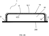
- the Fig. 2A shows a similar schematic sectional view of an insulation system 1 as the Fig. 1 , The same elements are provided with the same reference numerals and will not be explained again here. Additionally shows Fig. 2A an inner liner 18 provided between the component 200 to be insulated and the insulating surface 12.2 of the fiber molding.
- the inner liner is typically made of metal, for example made of stainless steel with material number WNr. 1.4541. It is in Fig. 2A the inner liner 18 is shown as resting on the component 200, thus forming some sort of additional layer on the component 200. It is understood, however, that the inner liner 18 may also be provided substantially only in the region A and B, that is, where in Fig. 1 the insulating surface 12.2 the component 200 contacted.
- the inner liner 18 may be provided between the component 200 and the insulating surface. It is understood that the inner liner is the size of the basis of Fig. 1 explained predefined proportion of the insulating surface 12.2 of the fiber molding in the area A and B, where the component to be insulated 200 contacted by the insulating surface 12.2 does not change.
- the inner liner 18 may serve, on the one hand, to provide additional protection against mechanical or thermal stresses for the insulating material of the fiber molded part 12. On the other hand, the molded fiber part 12 can be mounted or exchanged more easily so that greater processing and maintenance flexibility can be provided.
- the Fig. 2B shows a variant of in Fig. 2A shown embodiment. The material properties of the inner liner 18 may be the same.
- Fig. 2B the same reference numerals used.
- the inner liner 18 can also be provided so that it can assume the shape of the side facing the exhaust gas component side of the insulating body, so the fiber molding 12.
- Fig. 2B is the inner liner 18 at the side with the insulating surface 12.2.
- a preferably metallic inner liner 18, such as in Fig. 2A and 2 B can be used to easily provide a de- and remontability of the fiber molding.
- a preferably metallic inner liner has a protective function for the insulating body, so the fiber molding.
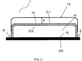
- Fig. 3 shows a further development of Fig. 2A ,
- the same elements are designated by the same reference numerals. Purely by way of example is in Fig. 3 from the in Fig. 2A shown embodiment. It is understood, however, that the in Fig. 3 embodiment shown and described below on each of the in connection with the Fig. 2A and the Fig. 2B described embodiments may be based.
- the shroud 14 may typically include a metallic sheath. It is also possible to provide a sheath made of a thermosetting thermoplastic material and / or an elastomeric plastic. In Fig. 3 the sheath 14 is shown detachably.
- Fig. 3 the sheath 14 is shown detachably.
- the entire casing 14 is shown as removable, it is understood that one could also provide a multi-part casing, of which only parts can be removed or opened and closed, such as by a folding mechanism (not here shown).
- the casing 14 can be pushed onto the fiber molded part 12 or pulled away from it.
- the sheath 14 is replaceable in this development.
- the sheath can be provided so that the outer sheath 14 is either completely or partially close or open, thus providing an outer shell 14 with the possibility of a variable opening or closing of the outer shell, so the sheath.
- This offers the insulation system the ability to quickly come to operating temperature corresponding to the exhaust system with closed shell 14 and to cause cooling of the component 200 by convection in the open variant, ie selectively connect or disconnect convection targeted.
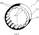
- the Fig. 4 shows a schematic view of a development of an insulation system 21 according to one or more of Fig. 1-3 , It is in Fig. 4 a component to be insulated is not shown, but only the insulation system 21.
- the insulation system 21 in Fig. 4 In turn, as already indicated in the Fig. 1-3 a fiber molding 22 on with an outwardly facing surface 22.1.
- the cylindrical shape of the fiber molding 22 suggests that the surface 22.1 represents the side away from a component to be insulated.
- the fiber molded part 22 indentations 26H.
- the number of indentations may be larger or smaller, according to the present applications.
- the recesses 26H are in Fig. 4 exemplary hemispherical and / or semi-cylindrical shape.
- Half Cylindrical Indentations have the advantage that they can be implemented more easily in terms of production technology / tools. It is understood, however, that other bodies or partial bodies with suitable geometric shapes can be selected so that one or more cavities are formed.
- the recesses 26H may also have a kind of honeycomb structure.
- the indentations 26H are provided in the insulating surface 22.2. It is understood that in Fig. 4 and subsequently in Fig. 5 Example shown, a cylindrical symmetry or tube symmetry shows, but there may be other body shapes, which may have a lower symmetry.
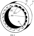
- Fig. 5 is the isolation system 21 off Fig. 4 for isolating a component 202 to be isolated, such as an exhaust gas component.
- the component 202 may be of the component 200 from the Fig. 1-3 correspond.
- the insulating surface 22.2 in Fig. 4 consists of many small sub-areas that limit the indentations 26H and lie between the respective indentations.
- This insulating surface 22. 2 ie the many small partial surfaces, contacts / contact the component 202 so that as many cavities 26 as indentations 26 H result.
- the sum of all small sub-areas again results in a predefined proportion of the insulating surface 22.2 of the fiber molded part, where the component 202 to be insulated is contacted by the insulating surface 22.2.
- the predefined fraction is typically at least 10% and a typical value in the sense of an upper limit may be about 90% of the insulating surface.
- Other values are also possible, in particular a value between a minimum of 25% to a maximum of 5
- an outer casing 24 is shown, which surrounds the surface 22.1 on the side facing away from the component 202 to be insulated.
- the introduced into the insulation system air chambers 26 H achieve the desired isolation effect, so that a greater proportion of the energy remains in the exhaust gas and practically not dissipated to the outside in the environment. There is virtually no convective heat transfer of the exhaust gas component into the environment. In addition to the thermal properties also results in an improved acoustic insulation. For example, it results in sound absorption in the range of 6.3 kHz at about 90%.
Description
- Die Erfindung betrifft ein Isolationssystem zur thermo-akustischen Isolierung einer zu isolierenden Abgaskomponente, sowie ein entsprechendes Verfahren zur Isolierung einer derartigen Abgaskomponente.
- Bevor auf die Wärmedämmung näher eingegangen wird, es ist nützlich, die spezifische Wärmekapazität eines Körpers zu definieren.
- Die Wärmekapazität C eines Stoffes ist der Quotient aus der Wärme Q, die man dem Körper zuführt, und der dadurch bewirkten Temperaturerhöhung ΔT:

- Die spezifische Wärmekapazität c, auch spezifische Wärme genannt, ergibt sich aus der Normierung der Wärmekapazität C auf die Masse des Stoffes. Anders ausgedrückt ist die spezifische Wärmekapazität eines Stoffes die Energie, die benötigt wird, um 1 kg dieses Stoffes um 1 K zu erwärmen:

- Die spezifische Wärmekapazität ist nur schwach temperaturabhängig. Da die spezifische Wärmekapazität c in der Regel als Materialkonstante vorliegt, schreibt man die Formel (2) häufig um als

- Bei der Wärmedämmung, beispielsweise bei Abgassystemen von Fahrzeugen, sind grundsätzlich drei Mechanismen zu betrachten, die Wärmeleitung, die Wärmestrahlung und die Konvektion.
- Unter Wärmeleitung, auch Wärmediffusion genannt, wird ein Wärmefluss infolge einer Temperaturdifferenz verstanden. Die Flussrichtung ist entsprechend des zweiten Hauptsatzes der Thermodynamik stets von der höheren zur geringeren Temperatur gerichtet. Dabei geht idealerweise keine Wärmeenergie verloren.
- Bei Wärmestrahlung wird elektromagnetische Strahlung von einem Festkörper, Fluiden oder Plasmen emittiert. Die emittierte Strahlungsleistung P ist dabei proportional zur vierten Potenz der Temperatur des abstrahlenden Körpers, d.h. P ∝ T 4 (Stefan-Boltzmann-Gesetz). Im Vakuum ist Wärmestrahlung die einzige Möglichkeit zur Übertragung von Wärmeenergie.
- Konvektion oder Wärmeübertragung ist ein weiterer Mechanismus zum Wärmetransport. Konvektion wird durch eine Strömung hervorgerufen, die Teilchen befördert. Beispielsweise kann ein strömendes Fluid Wärme von einer Oberfläche aufnehmen oder an sie abgeben. Eine Ursache für die transportierende Strömung können Temperaturschiede sein. Bei einer erzwungenen Konvektion wird der Teilchentransport durch äußere Einwirkung, zum Beispiel ein Gebläse oder eine Pumpe, hervorgerufen. Bei einer freien Konvektion, wird der Teilchentransport durch einen innerhalb des Mediums vorliegenden Temperaturgradienten hervorgerufen.
- In den zu dämmenden Systemen werden häufig Motoren mit hoher Geschwindigkeit gefahren, wodurch eine hohe Geräuschbelastung eintreten kann. Somit kommt zusätzlich zur Wärmedämmung der Aspekt der Schalldämmung hinzu.
- Die
DE 10 2010 0660071 A1 - Die
US 2009/197044 A1 offenbart einen Wärmeschild, welcher zusätzlich schallabsorbierenden Eigenschaften aufweist. - Die
US 2010/035078 A1 offenbart einen per Hand wickelbaren Hitzeschild und eine entsprechende Konstruktionsmethode wobei äußere und innere Schichten aus Metall sind, und in das Metall Täler und entsprechend Spitzen eingeprägt sind. - Die
EP 2 444 617 A1 offenbart einen Abgaskrümmer für einen Verbrennungsmotor mit einem abgasführenden Innenrohr und einer äußeren Ummantelung, wobei die Isolierung als in Form gepresstes Isolierformteil ausgebildet ist und zwischen der Ummantelung und dem Innenraum angeordnet ist, wobei das Isolierformteil ein Isolierfasergewebe und ein Bindemittel enthält. - Die
EP2 444 616 A1 offenbart ein heißgasführendes Bauteil, insbesondere für eine Abgasanlage eines Verbrennungsmotors, wobei am Bauteil eine Isolierung angeordnet ist, der wärmereflektierende und/oder wärmeabsorbierende Pigmente zugefügt sind. - Die
AT 133 379 B - Beispielhaft werden nachfolgend drei bekannten Arten der Dämmung / Isolierung aus der Praxis beschrieben.
- Ein erstes Beispiel ist die Luftspaltisolierung ohne Konvektion. Bei der Luftspaltisolierung ohne Konvektion liegt ein in sich abgeschlossenes Dämmsystem vor, in dem im Wesentlichen ruhende Luft als Dämmmaterial verwendet wird. Ein Vorteil dieser Art der Isolierung ist die geringe spezifische Wärmekapazität der Luft. Somit kann vom System nur eine geringe Wärmemenge aufgenommen werden kann. Durch diesen Umstand bleibt bei wärmegesättigtem Dämmmaterial, also wärmegesättigter Luft, die Wärmeenergie zum größten Teil dem zu isolierenden System erhalten. Weiterhin wird aufgrund der geringen Wärmeleitfähigkeit der Luft der Wärmeverlust durch Wärmeleitung sehr klein gehalten. Ein Nachteil dieser Methode ist hier die Wärmestrahlung, die auf die umliegenden Bauteile einwirken kann. Ferner ist nur eine sehr kleine Temperaturdifferenz über die Dämmzone hinaus möglich. Das bedeutet, die Oberflächentemperatur des Dämmsystems, also der Luft, liegt nur unwesentlich geringer als die Anwendungstemperatur, also die Temperatur des zu isolierenden Systems, beispielsweise der Abgaskomponente. Zusammenfassend lässt sich über die Luftspaltisolierung ohne Konvektion sagen, dass sie einen sehr guten Energieerhalt im zu isolierenden System bietet aber für umliegende Bauteile keinen ausreichenden Schutz durch aufgrund der hohen Oberflächentemperaturen garantiert. Ebenso wird die Umwelt kaum vor akustischen Emissionen geschützt.
- Ein weiteres Beispiel ist die Luftspaltisolierung mit Konvektion und Hitzeschild. Bei der Luftspaltisolierung mit Konvektion und Hitzeschild, klassisch häufig nur als Hitzeschild bezeichnet, liegt ein Dämmsystem vor, welches nicht in sich abgeschlossen ist. Es bietet erweiterte Einflussnahme der Umwelt. Bei dieser Art der Isolierung wird vor dem zu isolierenden Bauteil eine Art Schutzschild auf Abstand angebracht welches die Wärmestrahlung vor umliegenden Bauteilen abfangen soll, um diese zu schützen. Hier zeigen sich oben unter 1. beschriebenen Vor-und Nachteile in umgekehrter Position. Durch den ständigen Schichtwechsel der Luft kann die vom zu isolierenden System abgegebene Wärme immer wieder erneut aufgenommen werden, dies ist auch im Einklang mit Gleichung (3). Dies führt zu erhöhten Energieverlusten in diesem zu isolierenden System, da die aufzunehmende Wärmemenge der Isolierung, also des Luftspalts, praktisch niemals gegen Null gehen kann.
- Anders als bei der Luftspaltdämmung ohne Konvektion wird durch den Umstand der ständig wechselnden Luftschichten und damit verbundener Wärmeabführung auf der Oberfläche des Dämmsystems eine bei weitem geringere Temperatur gemessen als es die Ausgangstemperatur ist. Zudem wird durch die Funktion als Schutzschild die Belastung durch Wärmestrahlung umliegender Bauteile stark reduziert. Nachteilig bei diesem System ist die geringe akustische Absorption anzusehen. Zusammenfassend lässt sich über die Luftspaltisolierung mit Konvektion sagen, dass umliegende Bauteile sehr gut vor thermischen Einflüssen geschützt werden, dies aber zu Lasten der Energieerhaltung in dem zu isolierenden System, sowie der Vermeidung akustischer Emissionen in die Umwelt geht.
- Ein drittes Beispiel für Isoliersysteme sind solche, bei denen das Dämmmaterial / Isoliermaterial ein Füllstoff zwischen zu isolierendem System und metallischer Außenschale ist. Im Hochtemperaturbereich sind dies meist Glasfasern, beispielsweise Silikatfasern oder Keramikfasern, welche direkt auf zu isolierende Systeme appliziert werden. Dies ist auch aktuell eine der meist verwendeten Methoden im automobilen Sektor. Diese Isoliermethode bietet die Zwischenlösung zu den beiden erstgenannten. Vorteile sind die niedrigen Oberflächentemperaturen bei geringem Bauraum sowie eine gute akustische Absorption durch das Fasermaterial. In Bezug auf die Energieerhaltung im zu isolierenden System ist es eine Zwischenlösung. Es findet keine merkliche Konvektion statt, weshalb es sich zur Energieerhaltung besser eignet als die Hitzeschildisolierung. Jedoch bietet dieses System eine viel größere aufzunehmende Wärmemenge als die Luftspaltisolation ohne Konvektion, was in diesem Fall eine verminderte Energieerhaltung bedeutet. Ein weiterer Nachteil in Bezug auf die Energieerhaltung ist die fehlende Strahlungsreflexion, bedingt durch die Direktapplizierung welche ausschließlich Wärmeleitung zulässt. Zusammenfassend lässt sich sagen, dass dieses Isoliersystem der Mittelweg zwischen den beiden erstgenannten Systemen ist und dem entsprechend eine der häufigsten angewandten Methoden darstellt.
- Angesichts der Nachteile im Stand der Technik ist es Aufgabe der vorliegenden Erfindung, ein alternatives Dämmsystem bereitzustellen, welches das zu isolierende System isoliert und dabei die Umwelt vor Wärmebelastung und akustischer Belastung schützt.
- Diese Aufgabe wird durch Isolationssystem gemäß Patentanspruch 1 sowie ein entsprechendes Verfahren gemäß Patentanspruch 8 gelöst.
- Die Erfindung stellt bereit: ein Isolationssystem zur thermo-akustischen Isolierung einer zu isolierenden Abgaskomponente, umfassend ein Faserformteil mit einer der zu isolierenden Abgaskomponente abgewandten Fläche, wobei die abgewandte Fläche zumindest teilweise mit einer Ummantelung ummantelt ist, und mit einer Isolierfläche, die der zu isolierenden Abgaskomponente zugewandt ist, wobei das Faserformteil auf die zu isolierende Abgaskomponente derart applizierbar ist, dass sich zwischen einem Teil der Isolierfläche des Faserformteils und der zu isolierender Abgaskomponente mehrere geschlossene Hohlräume bilden, wobei ein vordefinierter Anteil der Isolierfläche des Faserformteils die zu isolierende Abgaskomponente kontaktiert, wobei der vordefinierte Anteil minimal 10 % und maximal 90% beträgt, insbesondere minimal 25 % bis maximal 55 %; wobei die Isolierfläche, die der zu isolierenden Abgaskomponente zugewandt ist, mehrere vordefinierte Einbuchtungen aufweist.
- Dabei soll ein Hohlraum als ein abgeschlossenes System, eine Kammer, verstanden werden. Dieses System, also der Hohlraum, wird durch die Isolierfläche des Faserformteils einerseits und die Oberfläche der zu isolierenden Abgaskomponente bzw. der zu isolierenden Bereiche dieser Abgaskomponente begrenzt und damit abgeschlossen. Als abgeschlossenes System bietet der Hohlraum den Vorteil, dass er Luft einschließt. Der Hohlraum wirkt also als ein Luftspeicher. Hierdurch ergibt sich aufgrund von Gleichung (3) eine niedrige aufzunehmende Wärmemenge des Dämmsystems, weil die eingeschlossene Luft nur eine geringe Masse besitzt. Dadurch, dass der Hohlraum abgeschlossen ist, findet praktisch keine merkliche Konvektion statt. Somit bleibt nach dem Erhitzen des Dämmsystems, also des Hohlraums, genauer der Luft im Hohlraum, mit geringer Wärmemenge die nahezu gesamte Wärmeenergie im zu isolierende System. Lediglich an den Kontaktflächen kann eine zusätzliche Wärmeaufnahme stattfinden. Da die Kontaktflächen jedoch klein und begrenzt sind, findet nur eine minimal größere Wärmeaufnahme über die Kontaktfläche statt. In Bezug auf die Wärmeleitfähigkeit bietet sich hier der Vorteil, dass Luft, insbesondere ruhende Luft ein Medium mit einer sehr niedrigen Wärmeleitfähigkeit darstellt. Anders als bei der Luftspaltisolierung ohne Konvektion ergibt sich aus der noch über dem Hohlraum liegenden Faserformteil, das beispielsweise eine Dämmfaser umfasst. Dieses kann insbesondere für niedrige Oberflächentemperaturen sorgen. Somit bleibt nahezu die gesamte Wärmeenergie im zu isolierenden System erhalten und die umliegenden Bauteile sind optimal geschützt, weil die Oberflächentemperaturen relativ niedrig bleiben.
- Das Faserformteil, also das Dämmmaterial weist eine zwar etwas höhere aber doch geringe Wärmeleitfähigkeit im Vergleich zur Luft im Hohlraum auf. Die Kontaktfläche des Faserformteils mit dem zu isolierenden System kann aber geringgehalten werden, nämlich beispielsweise lediglich 10%. Unterhalb von 10% können Probleme mit Instabilitäten entstehen. Ein typischer Wert im Sinne eine Obergrenze kann etwa 90% der Isolierfläche betragen, oberhalb von 90% verschwinden die Vorteile gegenüber einer vollständig kontaktierten Isolierfläche zusehends. Es sind aber auch andere Werte möglich, insbesondere ist ein Wert zwischen minimal 25% bis maximal 55 % möglich. Somit ergibt sich eine Art Symbiose aus einer herabgesetzten Wärmeleitfähigkeit des Systems. Aus der noch über dem Hohlraum liegenden Dämmfaser des Faserformteils ergibt sich somit die Möglichkeit, niedrige Oberflächentemperaturen zu erzielen. Somit bleibt praktisch die gesamte Wärmeenergie im zu isolierenden System erhalten und die umliegenden Bauteile sind aufgrund der geringen Oberflächentemperaturen gut geschützt.
- In dem Isolationssystem kann die Isolierfläche des Faserformteils mit Farbpigmenten beschichtet sein, die einen TSR, Total Solar Reflectance,-Wert von wenigstens 65% aufweisen, wobei der Anteil der Farbpigmente bezogen auf die Gesamtmasse des Faserformteils zwischen 1 - 5 % beträgt, vorzugsweise zwischen 1,5 - 3 %.
- Durch die Beschichtung des Faserformteils auf der warmseitigen Oberfläche mit einem Pigment mit hohem TSR Wert, Total Solar Reflection Value, insbesondere im NIR Bereich, Nah-InfrarotBereich, kann die Rückreflektion der Wärmestrahlung zusätzlich erhöht werden. Dies kann als ein künstlich in den Hohlräumen hervorgerufener Treibhauseffekt angesehen werden. Die emittierte Wärmestrahlung des zu isolierenden Systems, etwa der zu isolierenden Abgaskomponente, wird von der behandelten Oberfläche des Faserformteils reflektiert und größtenteils dem zu isolierenden System rückgeführt. Der absorbierte Teil der Strahlung trägt wiederrum zu der Wärmesättigung des Dämmsystems bei. Beispielsweise können die Farbpigmente ein Polier-Rutil auf Chrom/Antimon/Titan-Basis umfassen.
- Dabei kann zwischen der Isolierfläche des Faserformteils und der zu isolierenden Abgaskomponente ein Innenliner eingefügt sein, wobei es sich vorzugsweise um einen metallischen Innenliner handelt.
- Falls eine direkte Applizierung, also ein direkter Kontakt des Faserformteils mit der zu isolierenden Abgaskomponente nicht erwünscht oder gar schwierig ist, kann ein metallischer Innenliner verwendet werden. Dieser hat den Vorteil, dass eine De- und Remontierbarkeit des Faserformteils möglichst einfach bereitgestellt werden kann. Zusätzlich kann das Faserformteil, also insbesondere das Fasermaterial geschützt werden.
- In dem Isolationssystem kann die Ummantelung eine metallische Ummantelung oder ein duroplastisch- thermoplastischer Kunststoff oder ein Elastomer-Kunststoff umfassen.
- Neben den thermischen Eigenschaften zeichnen sich diese Kunststoffe auch durch gute akustische Eigenschaften im Hinblick auf Schalldämmung aus. ab. In Ausführung mit passender metallischer Ummantelung, kann diese typischerweise so vorgesehen werden, dass der Außenmantel zu schließen oder zu öffnen ist. Somit bietet sich die Möglichkeit einer variablen Öffnung oder Schließung der Außenhülle, also der Ummantelung. Damit bietet sich dem System die Möglichkeit, bei geschlossener Hülle schnell auf Betriebstemperatur entsprechend dem Abgassystem zu kommen und bei geöffneter Variante eine Kühlung des Bauteils durch Konvektion hervorzurufen, also Konvektion gezielt zuzuschalten oder abzuschalten.
- Dabei können die mehreren vordefinierten Einbuchtungen halbkugelförmige und/oder halbzylinderförmige Einbuchtungen sein, so dass die Hohlräume halbkugelförmig und/oder halbzylinderförmig ausbildbar sind.
- Die Einbuchtungen können als Luftkammern, also mit Luft gefüllte Hohlräume verstanden werden, wobei für jeden der Hohlräume die oben genannten Vorteile gelten. Zusätzlich lassen sich symmetrische, einfach herzustellen Formen bilden. Halbzylinderförmige Einbuchtungen haben den Vorteil, dass sie sich herstellungstechnisch / werkzeugtechnisch besonders einfach realisieren lassen und dabei die vorteilhaften Eigenschaften des Isolationssystems aufweisen. Es versteht sich, dass auch andere Körper- beziehungsweise Teilkörperformen gewählt werden können, so dass sich ein oder mehrere Hohlräume bilden lassen.
- Die Erfindung stellt ferner eine Abgaskomponente mit einer zumindest teilweise an der Komponente angeordneten Isolierung bereit, wobei die Isolierung als Isolationssystem wie oben beschrieben ausgebildet ist.
- Ebenso stellt die Erfindung einen Schalldämpfer bereit, umfassend mindestens eine Abgaskomponente wie oben beschrieben.
- Ferner stellt die Erfindung ein Verfahren zum thermo-akustischen Isolieren einer Abgaskomponente bereit, das Verfahren umfassend die Schritte: Bereitstellen eines Faserformteils mit einer der zu isolierenden Abgaskomponente abgewandten Fläche, wobei die abgewandte Fläche zumindest teilweise mit einer Ummantelung ummantelt ist, und mit einer Isolierfläche, die der Abgaskomponente zugewandt ist; Applizieren des Faserformteils auf die Abgaskomponente derart, dass sich zwischen einem Teil der Isolierfläche des Faserformteils und der zu isolierender Abgaskomponente mehrere geschlossene Hohlräume bildet; wobei ein vordefinierter Anteil der Isolierfläche des Faserformteils die zu isolierende Abgaskomponente kontaktiert, wobei der vordefinierte Anteil minimal 10% und maximal 90% beträgt, insbesondere minimal 25% bis maximal 55 %; wobei die Isolierfläche, die der zu isolierenden Abgaskomponente zugewandt ist, mehrere vordefinierte Einbuchtungen aufweist.
- Die Vorteile des Verfahrens und seiner Schritte wurden bereits entsprechend dem Isolationssystem oben beschrieben.
- In dem Verfahren kann die Isolierfläche des Faserformteils mit Farbpigmenten beschichtet sein, die einen TSR, Total Solar Reflectance, -Wert von wenigstens 65% aufweisen, wobei der Anteil der Farbpigmente bezogen auf die Gesamtmasse des Faserformteils zwischen 1 - 5 % beträgt, vorzugsweise zwischen 1,5 - 3 %.
- Beispielsweise können die Farbpigmente ein Polier-Rutil auf Chrom/Antimon/Titan-Basis umfassen.
- Dabei kann zwischen der Isolierfläche des Faserformteils und der zu isolierenden Abgaskomponente ein Innenliner eingefügt sein, wobei es sich vorzugsweise um einen metallischen Innenliner handelt.
- In dem Verfahren kann das Faserformteil ferner eine der zu isolierenden Abgaskomponente abgewandte Fläche umfassen, wobei die abgewandte Fläche zumindest teilweise mit einer Ummantelung ummantelt ist, wobei die Ummantelung eine metallische Ummantelung sein kann oder einen duroplastisch- thermoplastischen Kunststoff oder einen Elastomer-Kunststoff umfassen kann.
- In dem Verfahren können die mehreren, vordefinierten Einbuchtungen halbkugelförmig oder halbzylinderförmig ausgebildet sind.
- Hier versteht es sich wiederum, dass auch andere Körper- beziehungsweise Teilkörperformen gewählt werden können, so dass sich mehrere Hohlräume bilden lassen.
- Ein Beispiel für ein Anwendungsgebiet des beschriebenen Isolationssystems und des entsprechenden Verfahrens ist der Automobilsektor. Dabei ist es beispielsweise wichtig, die strengen Euronormen zu erfüllen, wonach Abgasenergie und -temperatur auf einem immer höheren Niveau gehalten werden muss, um die nachgeschalteten Aggregate im Abgasstrang wie z. B. DPF, Oxikat, SCR System usw. optimal zu betreiben und den Schadstoffausstoß zu senken. Allgemein geht es darum, Energieverluste des zu isolierenden Systems durch Energieabgabe in Form von Wärmeenergie, d.h. Wärmeleitung, Wärmestrahlung, Konvektion, und auch in Form von akustischer Energie, d.h. Schall, so gering wie möglich zu halten.
- Im Folgenden werden Ausführungsformen der Erfindung unter Bezugnahme auf die Zeichnungen beschrieben. Die beschriebenen Ausführungsformen sind in jeder Hinsicht lediglich als illustrativ und nicht als einschränkend anzusehen und verschiedene Kombinationen der angeführten Merkmale sind in der Erfindung eingeschlossen.
-
- Fig. 1
- Schematische Ansicht eines Isolationssystems
- Fig. 2A u. 2B
- Schematische Ansichten von Isolationssystemen mit Innenliner.
- Fig. 3
- Schematische Ansicht einer Weiterbildung eines Isolationssystems aus
Fig. 1 - 3 mit auswechselbarer Ummantelung. - Fig. 4
- Schematische Ansicht einer Weiterbildung eines Isolationssystems ohne zu isolierende Komponente.
- Fig. 5
- Schematische Ansicht einer Weiterbildung eines Isolationssystems.
-
Fig. 1 zeigt eine schematische Ansicht eines Isolationssystems 1 zur thermo-akustischen Isolierung einer zu isolierenden Komponente 200. Die zu isolierende Komponente 200 kann beispielsweise eine Abgaskomponente sein. Das Isolationssystem 1 inFig. 1 umfasst ein Faserformteil 12, welches ein Dämmmaterial, beispielsweise Fasern oder Vlies, umfasst. Das Faserformteil 12 hat eine der zu isolierenden Komponente 200 abgewandte Seite beziehungsweise Fläche, die mit dem Bezugszeichen 12.1 bezeichnet ist. Diese Fläche 12.1 ist inFig. 1 mit einer Ummantelung 14 ummantelt. In der schematischen Darstellung inFig. 1 liegt die Ummantelung 14 praktisch auf der Fläche 12.1 auf. - Das Faserformteil 12 hat ferner eine der zu isolierenden Komponente zugewandte Seite oder Fläche 12.2. Bei der Fläche 12.2 handelt es sich um eine Isolierfläche.
Fig. 1 zeigt eine stark vereinfachte Schnittzeichnung. Darin wird eine zu isolierende Komponente 200 durch ein Isolationssystem 1 mit einem Faserformteil 12 isoliert. Das Faserformteil 12 ist dabei derart auf die zu isolierende Komponente 200 appliziert, also aufgebracht, dass es die zu isolierende Komponente 200 nur mit einem Teil der Isolierfläche 12.2 kontaktiert. Dabei erfolgt der Kontakt durch die Isolierfläche 12.2 derart, dass ein Hohlraum 16 gebildet wird. Dabei kann der Hohlraum 16 auch als Kammer verstanden werden. Der Hohlraum 16 wird vollständig von der Isolierfläche 12.2 und der zu isolierenden Komponente 200 umschlossen bzw. begrenzt, also zwischen diesen Elementen gebildet. Der Hohlraum 16 ist typischerweise mit Luft gefüllt und kann auch als ein Luftspeicher angesehen werden. Es versteht sich, dass mehrere Hohlräume ähnlicher Art gebildet werden können und dassFig. 1 dabei nur einen Hohlraum zeigt. - Der Hohlraum 16 oder mehrere, separate Hohlräume, bilden jeweils ein abgeschlossenes Speichersystem. Somit kann der Hohlraum 16 Luft einschließen. Luft wiederum besitzt eine niedrige Wärmekapazität und kann damit aufgrund von Gleichung (3) nur eine geringe Wärmemenge des zu dämmenden Systems aufnehmen. Es findet praktisch keine Konvektion im Hohlraum 16 statt. Somit bleibt nahezu die gesamte Wärmeenergie im zu isolierenden System 200.
- In dem in
Fig. 1 gezeigten Beispiel kontaktiert die Isolierfläche 12.2 die Komponente 200 nur im Bereich der Punkte A und B. Es handelt sich also um einen vordefinierten Anteil der Isolierfläche 12.2 des Faserformteils im Bereich A und B, wo die zu isolierende Komponente 200 von der Isolierfläche 12.2 kontaktiert wird. Dabei kann der vordefinierte Anteil typischerweise wenigstens 10% betragen. Ein typischer Wert im Sinne einer Obergrenze kann 90% der Isolierfläche betragen. Andere Werte können ebenfalls möglich sein. Unterhalb von 10% kann es sein, dass es Probleme mit Instabilitäten gibt. Oberhalb von 90% verschwinden die Vorteile gegenüber einer vollständig kontaktierten Isolierfläche zusehends. Es sind aber auch andere Werte möglich, insbesondere ist ein Wert zwischen minimal 25% bis maximal 55 % möglich. - Lediglich dort, wo die Isolierfläche 12 die Komponente 200 kontaktiert, also an den Kontaktflächen im Bereich A und B kann eine zusätzliche Wärmeaufnahme des Faserformteils 12, also des Dämmmaterials stattfinden. Da die Kontaktflächen jedoch klein und begrenzt sind, findet nur eine sehr geringe Wärmeaufnahme über die Kontaktfläche statt. Ein weiterer Vorteil ist, dass das gesamte Faserformteil 12 Dämmmaterial umfasst. Somit wird der Hohlraum 16 im Bereich des Faserformteil 12 zusätzlich von Dämmmaterial umschlossen. Dieses Dämmmaterial kann wiederum dafür sorgen, dass an der der zu isolierenden Komponente abgewandten Seite 12.1 die Oberflächentemperatur deutlich verringert werden kann, so dass durch das Isolationssystem 1 die Umgebung geschützt werden kann. Somit kann nahezu die gesamte Wärmeenergie im zu isolierenden System erhalten bleiben und die umliegenden Bauteile sind gut geschützt.
- Die Isolierfläche 12.2 des Faserformteils 12 kann zusätzlich mit Farbpigmenten beschichtet sein, beispielsweise ein Polier-Rutil auf Chrom/Antimon/Titan-Basis, die einen TSR, Total Solar Reflectance, -Wert von wenigsten 65% aufweisen, wobei der Anteil der Farbpigmente bezogen auf die Gesamtmasse des Faserformteils zwischen 1 - 5 % beträgt, vorzugsweise zwischen 1,5 - 3 %. Somit kann zusätzlich auch noch möglicher Energieabgabe durch Wärmestrahlung begegnet werden und die Energie kann noch besser im zu isolierenden System erhalten bleiben.
- Die
Fig. 2A zeigt eine ähnliche schematische Schnittansicht eines Isolationssystems 1 wie dieFig. 1 . Dabei sind gleiche Elemente mit gleichen Bezugszeichen versehen und werden hier nicht erneut erläutert. Zusätzlich zeigtFig. 2A einen Innenliner 18, der zwischen der zu isolierenden Komponente 200 und der Isolierfläche 12.2 des Faserformteils vorgesehen ist. Dabei ist der Innenliner typischerweise aus Metall, beispielsweise aus Edelstahl mit Werkstoffnummer WNr. 1.4541. Dabei ist inFig. 2A der Innenliner 18 derart dargestellt, dass er auf der Komponente 200 aufliegt und somit eine Art zusätzliche Schicht auf der Komponente 200 bildet. Es versteht sich jedoch, dass der Innenliner 18 auch lediglich im Wesentlichen im Bereich A und B vorgesehen sein kann, also dort, wo inFig. 1 die Isolierfläche 12.2 die Komponente 200 kontaktiert. In diesen Kontaktbereichen A und B kann der Innenliner 18 zwischen der Komponente 200 und der Isolierfläche vorgesehen sein. Es versteht sich, dass der Innenliner die Größe des anhand vonFig. 1 erläuterten vordefinierten Anteil der Isolierfläche 12.2 des Faserformteils im Bereich A und B, wo die zu isolierende Komponente 200 von der Isolierfläche 12.2 kontaktiert nicht verändert. Der Innenliner 18 kann zum einen dazu dienen, für das Dämmmaterial des Faserformteils 12 einen zusätzlichen Schutz vor mechanischen oder thermischen Beanspruchungen bereitzustellen. Zum anderen kann eine das Faserformteil 12 einfacher montiert bzw. ausgetauscht werde, so dass hiermit eine größere Verarbeitungs- und Wartungsflexibilität bereitgestellt werden kann. DieFig. 2B zeigt eine Variante der inFig. 2A gezeigten Ausführungsform. Dabei können die Materialeigenschaften des Innenliners 18 dieselben sein. Ebenso werden inFig. 2B dieselben Bezugszeichen verwendet. InFig. 2B ist gezeigt, dass der Innenliner 18 auch so vorgesehen sein kann, dass er die Form der zur Abgaskomponente hin gerichteten Seite des Dämmkörpers, also des Faserformteils 12 annehmen kann. InFig. 2B liegt der Innenliner 18 an der Seite mit der Isolierfläche 12.2 an. Ein vorzugsweise metallischer Innenliner 18, wie beispielsweise inFig. 2A und2B gezeigt, kann verwendet werden, um auf einfache Weise eine De- und Remontierbarkeit des Faserformteils bereitzustellen. Zusätzlich hat ein vorzugsweise metallischer Innenliner eine Schutzfunktion für den Dämmkörper, also das Faserformteil. - Die
Fig. 3 zeigt eine weitere Weiterbildung derFig. 2A . Dabei werden gleiche Elemente mit gleichen Bezugszeichen bezeichnet. Rein beispielhaft wird inFig. 3 von der inFig. 2A gezeigten Ausführungsform ausgegangen. Es versteht sich jedoch, dass die inFig. 3 gezeigte und im Folgenden beschriebene Ausführungsform auf jeder der im Zusammenhang mit derFig. 2A und derFig. 2B beschriebenen Ausführungsformen basieren kann. In derFig. 3 kann die Ummantelung 14 typischerweise eine metallische Ummantelung umfassen. Ebenso ist es möglich, eine Ummantelung aus einem duroplastisch- thermoplastischen Kunststoff und/oder einem Elastomer-Kunststoff vorzusehen. InFig. 3 ist die Ummantelung 14 abnehmbar gezeigt. Obwohl in Fig. 14 in einfacher Weise die gesamte Ummantelung 14 als abnehmbar dargestellt ist, versteht es sich, dass man auch eine mehrteilige Ummantelung vorsehen könnte, von der lediglich Teile abnehmbar oder zu öffnen und zu schließen sind, etwa durch einen Klappmechanismus (hier nicht gezeigt). In derFig. 3 kann die Ummantelung 14 beispielsweise in Richtung des Doppelpfeils P auf das Faserformteil 12 aufgeschoben bzw. von diesem abgezogen werden. Somit ist die Ummantelung 14 in dieser Weiterbildung auswechselbar. In Ausführung mit passender metallischer Ummantelung, kann die Ummantelung so vorgesehen werden, dass der Außenmantel 14 entweder ganz oder teilweise zu schließen oder zu öffnen ist, somit sich eine Außenhülle 14 bietet mit der Möglichkeit einer variablen Öffnung oder Schließung der Außenhülle, also der Ummantelung. Damit bietet sich dem Isolationssystem die Möglichkeit, bei geschlossener Hülle 14 schnell auf Betriebstemperatur entsprechend dem Abgassystem zu kommen und bei geöffneter Variante eine Kühlung der Komponente 200 durch Konvektion hervorzurufen, also Konvektion gezielt zuzuschalten oder abzuschalten. - Die
Fig. 4 zeigt eine schematische Ansicht einer Weiterbildung eines Isolationssystems 21 entsprechend einer oder mehrerer derFig. 1 - 3 . Dabei ist inFig. 4 eine zu isolierende Komponente nicht gezeigt, sondern nur das Isolationssystem 21. Das Isolationssystem 21 inFig. 4 weist wiederum, wie bereits in denFig. 1 - 3 ein Faserformteil 22 auf mit einer nach außen gerichteten Fläche 22.1. Die zylindrische Form des Faserformteils 22 legt nahe, dass die Fläche 22.1 die von einer zu isolierenden Komponente abgewandte Seite darstellt. Auf der Innenseite des Zylinders weist das Faserformteil 22 Einbuchtungen 26H auf. Obwohl in derFig. 4 achtzehn Einbuchtungen gezeichnet sind, versteht es sich, dass die Zahl der Einbuchtungen größer oder kleiner sein kann, entsprechend den vorliegenden Anwendungen. Die Einbuchtungen 26H sind inFig. 4 beispielhaft halbkugelförmig und/oder halbzylinderförmig ausgebildet. Halbzylinderförmige Einbuchtungen haben den Vorteil, dass sie sich herstellungstechnisch / werkzeugtechnisch einfacher realisieren lassen. Es versteht sich aber, dass auch andere Körper oder Teilkörper mit geeigneten geometrischen Formen gewählt werden können, so dass sich ein oder mehrere Hohlräume bilden. Beispielsweise können die Einbuchtungen 26H auch eine Art Wabenstruktur aufweisen. Die Einbuchtungen 26H sind in die Isolierfläche 22.2 vorgesehen. Es versteht sich, dass das inFig. 4 und nachfolgend inFig. 5 dargestellte Beispiel eine zylindrische Symmetrie bzw. Rohrsymmetrie zeigt, es aber ebenso andere Körperformen geben kann, die eine geringere Symmetrie aufweisen können. - In
Fig. 5 ist das Isolationssystem 21 ausFig. 4 zum Isolieren einer zu isolierenden Komponente 202, etwa einer Abgaskomponente gezeigt. Die Komponente 202 kann der Komponente 200 aus denFig. 1 - 3 entsprechen. Die Isolierfläche 22.2 inFig. 4 besteht aus vielen kleinen Teilflächen, die die Einbuchtungen 26H begrenzen bzw. zwischen den jeweiligen Einbuchtungen liegen. Diese Isolierfläche 22.2, d.h. die vielen kleinen Teilflächen, kontaktiert / kontaktieren die Komponente 202, so dass sich ebenso viele Hohlräume 26 wie Einbuchtungen 26H ergeben. Dabei ergibt die Summe aller kleiner Teilflächen wiederum einen vordefinierten Anteil der Isolierfläche 22.2 des Faserformteils, wo die zu isolierende Komponente 202 von der Isolierfläche 22.2 kontaktiert wird. Dabei liegt der vordefinierte Anteil wiederum typischerweise bei wenigstens 10% und ein typischer Wert im Sinne eine Obergrenze kann etwa 90% der Isolierfläche betragen. Andere Werte sind ebenfalls möglich, insbesondere ist ein Wert zwischen minimal 25% bis maximal 55 % möglich. - In
Fig. 5 ist ferner eine äußere Ummantelung 24 gezeigt, die auf der von der zu isolierenden Komponente 202 abgewandten Seite die Fläche 22.1 umgibt. - Die in das Isolationssystem eingebrachten Luftkammern 26 H erzielen den gewünschten Isolationseffekt, so dass ein größerer Anteil der Energie im Abgas verbleibt und praktisch nicht nach außen in die Umgebung dissipiert. Es findet praktisch kein konvektiver Wärmeübergang der Abgaskomponente in die Umgebung statt. Zusätzlich zu den thermischen Eigenschaften ergibt sich auch eine verbesserte akustische Dämmung. Es ergibt sich beispielsweise Schallabsorption im Bereich von 6,3 kHz bei ca. 90 % liegt.
Claims (12)
- Isolationssystem (1, 21) zur thermo-akustischen Isolierung einer zu isolierenden Abgaskomponente (200, 202), umfassend:ein Faserformteil (12, 22) mit einer der zu isolierenden Abgaskomponente (200, 202) abgewandten Fläche (12.1, 22.1), wobei die abgewandte Fläche (12.1, 22.1) zumindest teilweise mit einer Ummantelung (14, 24) ummantelt ist, und mit einer Isolierfläche (12.2, 22.2), die der zu isolierenden Abgaskomponente (200, 202) zugewandt ist, wobei das Faserformteil (12, 22) auf die zu isolierende Abgaskomponente (200, 202) derart applizierbar ist, dass sich zwischen einem Teil der Isolierfläche (12.2, 22.2) des Faserformteils (12, 22) und der zu isolierender Abgaskomponente (200, 202) mehrere geschlossene Hohlräume (16, 26) bilden;wobei ein vordefinierter Anteil der Isolierfläche (12.2, 22.2) des Faserformteils (12, 22) die zu isolierende Abgaskomponente (200, 202) kontaktiert, wobei der vordefinierte Anteil minimal 10% und maximal 90% beträgt, insbesondere minimal 25% bis maximal 55 %;wobei die Isolierfläche (12.2, 22.2), die der zu isolierenden Abgaskomponente (200, 202) zugewandt ist, mehrere vordefinierte Einbuchtungen (26H) aufweist.
- Isolationssystem (1, 21) gemäß Anspruch 1, wobei die Isolierfläche (12.2, 22.2) des Faserformteils mit Farbpigmenten beschichtet ist, die einen TSR, Total Solar Reflectance,-Wert von wenigstens 65% aufweisen, wobei der Anteil der Farbpigmente bezogen auf die Gesamtmasse des Faserformteils zwischen 1 - 5 % beträgt, vorzugsweise zwischen 1,5 - 3 %.
- Isolationssystem (1, 21) gemäß Anspruch 1, wobei zwischen der Isolierfläche (12.2, 22.2) des Faserformteils (12, 22) und der zu isolierenden Abgaskomponente (200, 202) ein Innenliner eingefügt ist, wobei es sich vorzugsweise um einen metallischen Innenliner handelt.
- Isolationssystem (1, 21) gemäß wenigstens einem der Ansprüche 1 - 3, wobei die Ummantelung (14, 24) eine metallische Ummantelung oder einen duroplastischthermoplastischer Kunststoff oder ein Elastomer-Kunststoff umfasst.
- Isolationssystem (1, 21) gemäß Anspruch 1, wobei die Einbuchtungen (26H) halbkugelförmige und/oder halbzylinderförmige Einbuchtungen sind, so dass die geschlossenen Hohlräume (26) halbkugelförmig und/oder halbzylinderförmig ausbildbar sind.
- Abgaskomponente mit einer zumindest teilweise an der Abgaskomponente (200, 202) angeordneten Isolierung, wobei die Isolierung als Isolationssystem (1, 21) gemäß einem der Ansprüche 1 - 5 ausgebildet ist.
- Schalldämpfer umfassend mindestens eine Abgaskomponente gemäß Anspruch 6.
- Verfahren zum thermo-akustischen Isolieren einer Abgaskomponente, umfassend die Schritte:Bereitstellen eines Faserformteils (12, 22) mit einer der zu isolierenden Abgaskomponente (200, 202) abgewandten Fläche, wobei die abgewandte Fläche (12.1, 22.1) zumindest teilweise mit einer Ummantelung (14, 24) ummantelt ist, und mit einer Isolierfläche (12.2, 22.2), die der Abgaskomponente zugewandt ist;Applizieren des Faserformteils (12, 22) auf die Abgaskomponente derart, dass sich zwischen einem Teil der Isolierfläche (12.2, 22.2) des Faserformteils (12, 22) und der zu isolierender Abgaskomponente (200, 202) mehrere geschlossene Hohlräume (16, 26) bilden;wobei ein vordefinierter Anteil der Isolierfläche (12.2, 22.2) des Faserformteils (12, 22) die zu isolierende Abgaskomponente (200, 202) kontaktiert, wobei der vordefinierte Anteil minimal 10% und maximal 90% beträgt, insbesondere minimal 25% bis maximal 55 %;wobei die Isolierfläche (12.2, 22.2), die der zu isolierenden Abgaskomponente (200, 202) zugewandt ist, mehrere vordefinierte Einbuchtungen (26H) aufweist.
- Verfahren gemäß Anspruch 8, wobei die Isolierfläche (12.2, 22.2) des Faserformteils (12, 22) mit Farbpigmenten beschichtet ist, die einen TSR, Total Solar Reflectance, -Wert von wenigstens 65% aufweisen, wobei der Anteil der Farbpigmente bezogen auf die Gesamtmasse des Faserformteils (12, 22) zwischen 1 - 5 % beträgt, vorzugsweise zwischen 1,5 - 3 %..
- Verfahren gemäß Anspruch 8 oder 9, wobei zwischen der Isolierfläche (12.2, 22.2) des Faserformteils (12, 22) und der zu isolierenden Abgaskomponente (200, 202) ein Innenliner eingefügt ist, wobei es sich vorzugsweise um einen metallischen Innenliner handelt.
- Verfahren gemäß wenigstens einem der Ansprüche 8 - 10, wobei das Faserformteil (12, 22) ferner eine der zu isolierenden Abgaskomponente (200, 202) abgewandte Fläche (12.1, 22.1) umfasst, wobei die abgewandte Fläche (12.1, 22.1) zumindest teilweise mit einer Ummantelung (14, 24) ummantelt ist, wobei die Ummantelung (14, 24) eine metallische Ummantelung ist oder einen duroplastisch- thermoplastischer Kunststoff oder ein Elastomer-Kunststoff umfasst.
- Verfahren gemäß Anspruch 8, wobei die Einbuchtungen (26H) halbkugelförmig oder halbzylinderförmig ausgebildet sind.
Priority Applications (5)
| Application Number | Priority Date | Filing Date | Title |
|---|---|---|---|
| EP15184579.9A EP3141721B1 (de) | 2015-09-10 | 2015-09-10 | Reflektierendes isolationssystem |
| US15/259,532 US9885268B2 (en) | 2015-09-10 | 2016-09-08 | Reflective insulation system |
| KR1020160116741A KR101866653B1 (ko) | 2015-09-10 | 2016-09-09 | 반사형 절연 시스템 |
| JP2016176427A JP6459072B2 (ja) | 2015-09-10 | 2016-09-09 | 反射性絶縁システム |
| CN201610819503.0A CN107060977B (zh) | 2015-09-10 | 2016-09-12 | 反射式隔离系统 |
Applications Claiming Priority (1)
| Application Number | Priority Date | Filing Date | Title |
|---|---|---|---|
| EP15184579.9A EP3141721B1 (de) | 2015-09-10 | 2015-09-10 | Reflektierendes isolationssystem |
Publications (2)
| Publication Number | Publication Date |
|---|---|
| EP3141721A1 EP3141721A1 (de) | 2017-03-15 |
| EP3141721B1 true EP3141721B1 (de) | 2019-05-29 |
Family
ID=54106212
Family Applications (1)
| Application Number | Title | Priority Date | Filing Date |
|---|---|---|---|
| EP15184579.9A Active EP3141721B1 (de) | 2015-09-10 | 2015-09-10 | Reflektierendes isolationssystem |
Country Status (5)
| Country | Link |
|---|---|
| US (1) | US9885268B2 (de) |
| EP (1) | EP3141721B1 (de) |
| JP (1) | JP6459072B2 (de) |
| KR (1) | KR101866653B1 (de) |
| CN (1) | CN107060977B (de) |
Families Citing this family (2)
| Publication number | Priority date | Publication date | Assignee | Title |
|---|---|---|---|---|
| WO2018189429A1 (fr) * | 2017-04-11 | 2018-10-18 | Faurecia Systemes D'echappement | Vanne et ligne d'échappement comprenant une telle vanne |
| US10822807B2 (en) | 2019-02-18 | 2020-11-03 | Royal Building Products (Usa) Inc. | Assembly for improved insulation |
Citations (1)
| Publication number | Priority date | Publication date | Assignee | Title |
|---|---|---|---|---|
| AT133379B (de) * | 1932-03-16 | 1933-05-26 | Werner Dipl Ing Genest | Isoliermatte. |
Family Cites Families (11)
| Publication number | Priority date | Publication date | Assignee | Title |
|---|---|---|---|---|
| JPH07156329A (ja) * | 1993-12-07 | 1995-06-20 | Sumitomo Metal Ind Ltd | 複合管 |
| JP3514358B2 (ja) * | 1997-05-08 | 2004-03-31 | 東海ゴム工業株式会社 | 管体用防音カバー及びその製造方法 |
| DE59914322D1 (de) * | 1998-10-05 | 2007-06-14 | Scambia Ind Dev Ag | Abgasleitelement und Verfahren zur Herstellung eines Abgasleitelements |
| DE20213228U1 (de) * | 2002-08-23 | 2002-10-31 | Carcoustics Tech Ct Gmbh & Co | Mehrlagiges Schall- und Wärmeisolationsteil |
| US20100035078A1 (en) * | 2007-01-11 | 2010-02-11 | Staudt Eric K | Embossed thermal shield and methods of construction and installation |
| US20090197044A1 (en) * | 2008-02-04 | 2009-08-06 | Pelzer Acoustic Products, Llc | Absorptive Heat Shield |
| DE102010060071A1 (de) * | 2010-10-20 | 2012-05-10 | Dr. Ing. H.C. F. Porsche Aktiengesellschaft | Teil einer Abgasanlage für einen Verbrennungsmotor |
| DE102010048974A1 (de) * | 2010-10-20 | 2012-04-26 | Isolite Gmbh | Isolierformteil |
| DE102010048975A1 (de) * | 2010-10-20 | 2012-04-26 | Isolite Gmbh | Heißgasführendes Bauteil |
| DE102010048973A1 (de) | 2010-10-20 | 2012-04-26 | Isolite Gmbh | Abgaskrümmer |
| DE202012010993U1 (de) * | 2012-11-16 | 2013-11-20 | Reinz-Dichtungs-Gmbh | Hitzeschild |
-
2015
- 2015-09-10 EP EP15184579.9A patent/EP3141721B1/de active Active
-
2016
- 2016-09-08 US US15/259,532 patent/US9885268B2/en active Active
- 2016-09-09 KR KR1020160116741A patent/KR101866653B1/ko active IP Right Grant
- 2016-09-09 JP JP2016176427A patent/JP6459072B2/ja active Active
- 2016-09-12 CN CN201610819503.0A patent/CN107060977B/zh active Active
Patent Citations (1)
| Publication number | Priority date | Publication date | Assignee | Title |
|---|---|---|---|---|
| AT133379B (de) * | 1932-03-16 | 1933-05-26 | Werner Dipl Ing Genest | Isoliermatte. |
Also Published As
| Publication number | Publication date |
|---|---|
| CN107060977B (zh) | 2019-08-09 |
| KR101866653B1 (ko) | 2018-07-04 |
| JP6459072B2 (ja) | 2019-01-30 |
| JP2017053354A (ja) | 2017-03-16 |
| US9885268B2 (en) | 2018-02-06 |
| CN107060977A (zh) | 2017-08-18 |
| KR20170031075A (ko) | 2017-03-20 |
| US20170074136A1 (en) | 2017-03-16 |
| EP3141721A1 (de) | 2017-03-15 |
Similar Documents
| Publication | Publication Date | Title |
|---|---|---|
| EP3141721B1 (de) | Reflektierendes isolationssystem | |
| EP2444616B1 (de) | Heissgasführendes Bauteil | |
| DE102017111703A1 (de) | Faserhaltiger Fahrzeugunterbodenschutz | |
| DE102016002128B4 (de) | Einen Lichtstrahl absorbierender optischer Absorber | |
| EP3307922B1 (de) | Verfahren zur beschichtung der oberfläche eines geschlossenen kühlkanals eines kolbens für einen verbrennungsmotor | |
| EP2444617B1 (de) | Abgaskrümmer | |
| EP0362242B1 (de) | Fassadenbekleidung | |
| DE102008031083A1 (de) | Verdampferbaugruppe für einen Verdampferbrenner eines Heizgerätes, insbesondere für ein Fahrzeug | |
| DE102008052631A1 (de) | Gasdynamische Druckwellenmaschine | |
| DE102013003155A1 (de) | Wavebreaker zum Einbau in Infrarotheizungen zur Reduzierung der Oberflächentemperatur der Strahlungsfläche. Verbesserung der Wärmeverteilung in dem zu beheizendem Raum, so wie Erhöhung der Strahlungsreichweite | |
| DE102016209603A1 (de) | Brennkraftmaschine mit zwei Abgasturboladern | |
| DE102011086014A1 (de) | Antriebssystem für ein Kraftfahrzeug mit einem temperaturgesteuerten Dämpfungselement | |
| DE102010008386B4 (de) | Druckwellenlader | |
| DE102018112136A1 (de) | Brechbare leitung zur verwendung bei einem kraftfahrzeug-lufteinlasssystem | |
| DE102014111235A1 (de) | Leitung mit Wölbstruktur | |
| DE102004040583B4 (de) | Schalldämpfer insbesondere für die Abgasanlage eines Kraftfahrzeugs | |
| DE102017223485A1 (de) | Abgaskrümmer sowie Verfahren zur Herstellung eines Abgaskrümmers | |
| DE802854C (de) | Einrichtung zur Daempfung von Abgas- bzw. Ansaugluft-Schwingungen in Verbindung mit Waermeaustauscher, insbesondere fuer Brennkraft-maschinen | |
| DE102012200397A1 (de) | Leitungselement für den Abgasstrang eines Kraftfahrzeugs und Verfahren zu dessen Herstellung | |
| DE102005043131A1 (de) | Luftschalldämpfungselement für ein Abgasanlagenelement | |
| DE112014001018T5 (de) | Herstellungsartikel zur Sicherung eines Katalysator-Substrats | |
| DE2934677C2 (de) | Mineralfaserdämmstoff und Verfahren zu seiner Herstellung | |
| DE102010038005A1 (de) | Verfahren und Vorrichtung zum Heizen von Räumen | |
| DE202014006236U1 (de) | Isolierung für mit Heißgas in Berührung kommende Teile einer Schmalflächenbeschichtungsvorrichtung, insbesondere für schlauch- oder rohrförmige Führungen für Heißgas | |
| EP1638683B8 (de) | Verfahren zum herstellen eines absorberhaltigen faserproduktes |
Legal Events
| Date | Code | Title | Description |
|---|---|---|---|
| PUAI | Public reference made under article 153(3) epc to a published international application that has entered the european phase |
Free format text: ORIGINAL CODE: 0009012 |
|
| STAA | Information on the status of an ep patent application or granted ep patent |
Free format text: STATUS: THE APPLICATION HAS BEEN PUBLISHED |
|
| AK | Designated contracting states |
Kind code of ref document: A1 Designated state(s): AL AT BE BG CH CY CZ DE DK EE ES FI FR GB GR HR HU IE IS IT LI LT LU LV MC MK MT NL NO PL PT RO RS SE SI SK SM TR |
|
| AX | Request for extension of the european patent |
Extension state: BA ME |
|
| STAA | Information on the status of an ep patent application or granted ep patent |
Free format text: STATUS: REQUEST FOR EXAMINATION WAS MADE |
|
| 17P | Request for examination filed |
Effective date: 20170831 |
|
| RBV | Designated contracting states (corrected) |
Designated state(s): AL AT BE BG CH CY CZ DE DK EE ES FI FR GB GR HR HU IE IS IT LI LT LU LV MC MK MT NL NO PL PT RO RS SE SI SK SM TR |
|
| STAA | Information on the status of an ep patent application or granted ep patent |
Free format text: STATUS: EXAMINATION IS IN PROGRESS |
|
| 17Q | First examination report despatched |
Effective date: 20180309 |
|
| GRAP | Despatch of communication of intention to grant a patent |
Free format text: ORIGINAL CODE: EPIDOSNIGR1 |
|
| STAA | Information on the status of an ep patent application or granted ep patent |
Free format text: STATUS: GRANT OF PATENT IS INTENDED |
|
| RIC1 | Information provided on ipc code assigned before grant |
Ipc: F01N 1/24 20060101ALI20181023BHEP Ipc: B32B 15/08 20060101ALI20181023BHEP Ipc: F01N 13/14 20100101AFI20181023BHEP Ipc: B32B 15/18 20060101ALI20181023BHEP |
|
| INTG | Intention to grant announced |
Effective date: 20181126 |
|
| GRAS | Grant fee paid |
Free format text: ORIGINAL CODE: EPIDOSNIGR3 |
|
| RIN1 | Information on inventor provided before grant (corrected) |
Inventor name: KNOLL, MICHAEL Inventor name: KUEHN, MANUEL PETER |
|
| GRAA | (expected) grant |
Free format text: ORIGINAL CODE: 0009210 |
|
| STAA | Information on the status of an ep patent application or granted ep patent |
Free format text: STATUS: THE PATENT HAS BEEN GRANTED |
|
| AK | Designated contracting states |
Kind code of ref document: B1 Designated state(s): AL AT BE BG CH CY CZ DE DK EE ES FI FR GB GR HR HU IE IS IT LI LT LU LV MC MK MT NL NO PL PT RO RS SE SI SK SM TR |
|
| REG | Reference to a national code |
Ref country code: GB Ref legal event code: FG4D Free format text: NOT ENGLISH |
|
| RIN1 | Information on inventor provided before grant (corrected) |
Inventor name: KUEHN, MANUEL PETER Inventor name: KNOLL, MICHAEL |
|
| REG | Reference to a national code |
Ref country code: CH Ref legal event code: EP |
|
| REG | Reference to a national code |
Ref country code: AT Ref legal event code: REF Ref document number: 1138396 Country of ref document: AT Kind code of ref document: T Effective date: 20190615 |
|
| REG | Reference to a national code |
Ref country code: DE Ref legal event code: R096 Ref document number: 502015009170 Country of ref document: DE |
|
| REG | Reference to a national code |
Ref country code: IE Ref legal event code: FG4D Free format text: LANGUAGE OF EP DOCUMENT: GERMAN |
|
| REG | Reference to a national code |
Ref country code: NL Ref legal event code: FP |
|
| REG | Reference to a national code |
Ref country code: SE Ref legal event code: TRGR |
|
| REG | Reference to a national code |
Ref country code: LT Ref legal event code: MG4D |
|
| PG25 | Lapsed in a contracting state [announced via postgrant information from national office to epo] |
Ref country code: FI Free format text: LAPSE BECAUSE OF FAILURE TO SUBMIT A TRANSLATION OF THE DESCRIPTION OR TO PAY THE FEE WITHIN THE PRESCRIBED TIME-LIMIT Effective date: 20190529 Ref country code: NO Free format text: LAPSE BECAUSE OF FAILURE TO SUBMIT A TRANSLATION OF THE DESCRIPTION OR TO PAY THE FEE WITHIN THE PRESCRIBED TIME-LIMIT Effective date: 20190829 Ref country code: AL Free format text: LAPSE BECAUSE OF FAILURE TO SUBMIT A TRANSLATION OF THE DESCRIPTION OR TO PAY THE FEE WITHIN THE PRESCRIBED TIME-LIMIT Effective date: 20190529 Ref country code: ES Free format text: LAPSE BECAUSE OF FAILURE TO SUBMIT A TRANSLATION OF THE DESCRIPTION OR TO PAY THE FEE WITHIN THE PRESCRIBED TIME-LIMIT Effective date: 20190529 Ref country code: HR Free format text: LAPSE BECAUSE OF FAILURE TO SUBMIT A TRANSLATION OF THE DESCRIPTION OR TO PAY THE FEE WITHIN THE PRESCRIBED TIME-LIMIT Effective date: 20190529 Ref country code: PT Free format text: LAPSE BECAUSE OF FAILURE TO SUBMIT A TRANSLATION OF THE DESCRIPTION OR TO PAY THE FEE WITHIN THE PRESCRIBED TIME-LIMIT Effective date: 20190930 Ref country code: LT Free format text: LAPSE BECAUSE OF FAILURE TO SUBMIT A TRANSLATION OF THE DESCRIPTION OR TO PAY THE FEE WITHIN THE PRESCRIBED TIME-LIMIT Effective date: 20190529 |
|
| PG25 | Lapsed in a contracting state [announced via postgrant information from national office to epo] |
Ref country code: GR Free format text: LAPSE BECAUSE OF FAILURE TO SUBMIT A TRANSLATION OF THE DESCRIPTION OR TO PAY THE FEE WITHIN THE PRESCRIBED TIME-LIMIT Effective date: 20190830 Ref country code: BG Free format text: LAPSE BECAUSE OF FAILURE TO SUBMIT A TRANSLATION OF THE DESCRIPTION OR TO PAY THE FEE WITHIN THE PRESCRIBED TIME-LIMIT Effective date: 20190829 Ref country code: RS Free format text: LAPSE BECAUSE OF FAILURE TO SUBMIT A TRANSLATION OF THE DESCRIPTION OR TO PAY THE FEE WITHIN THE PRESCRIBED TIME-LIMIT Effective date: 20190529 Ref country code: LV Free format text: LAPSE BECAUSE OF FAILURE TO SUBMIT A TRANSLATION OF THE DESCRIPTION OR TO PAY THE FEE WITHIN THE PRESCRIBED TIME-LIMIT Effective date: 20190529 |
|
| PG25 | Lapsed in a contracting state [announced via postgrant information from national office to epo] |
Ref country code: SK Free format text: LAPSE BECAUSE OF FAILURE TO SUBMIT A TRANSLATION OF THE DESCRIPTION OR TO PAY THE FEE WITHIN THE PRESCRIBED TIME-LIMIT Effective date: 20190529 Ref country code: RO Free format text: LAPSE BECAUSE OF FAILURE TO SUBMIT A TRANSLATION OF THE DESCRIPTION OR TO PAY THE FEE WITHIN THE PRESCRIBED TIME-LIMIT Effective date: 20190529 Ref country code: EE Free format text: LAPSE BECAUSE OF FAILURE TO SUBMIT A TRANSLATION OF THE DESCRIPTION OR TO PAY THE FEE WITHIN THE PRESCRIBED TIME-LIMIT Effective date: 20190529 Ref country code: CZ Free format text: LAPSE BECAUSE OF FAILURE TO SUBMIT A TRANSLATION OF THE DESCRIPTION OR TO PAY THE FEE WITHIN THE PRESCRIBED TIME-LIMIT Effective date: 20190529 Ref country code: DK Free format text: LAPSE BECAUSE OF FAILURE TO SUBMIT A TRANSLATION OF THE DESCRIPTION OR TO PAY THE FEE WITHIN THE PRESCRIBED TIME-LIMIT Effective date: 20190529 |
|
| PG25 | Lapsed in a contracting state [announced via postgrant information from national office to epo] |
Ref country code: SM Free format text: LAPSE BECAUSE OF FAILURE TO SUBMIT A TRANSLATION OF THE DESCRIPTION OR TO PAY THE FEE WITHIN THE PRESCRIBED TIME-LIMIT Effective date: 20190529 |
|
| REG | Reference to a national code |
Ref country code: DE Ref legal event code: R097 Ref document number: 502015009170 Country of ref document: DE |
|
| PG25 | Lapsed in a contracting state [announced via postgrant information from national office to epo] |
Ref country code: TR Free format text: LAPSE BECAUSE OF FAILURE TO SUBMIT A TRANSLATION OF THE DESCRIPTION OR TO PAY THE FEE WITHIN THE PRESCRIBED TIME-LIMIT Effective date: 20190529 |
|
| PLBE | No opposition filed within time limit |
Free format text: ORIGINAL CODE: 0009261 |
|
| STAA | Information on the status of an ep patent application or granted ep patent |
Free format text: STATUS: NO OPPOSITION FILED WITHIN TIME LIMIT |
|
| PG25 | Lapsed in a contracting state [announced via postgrant information from national office to epo] |
Ref country code: PL Free format text: LAPSE BECAUSE OF FAILURE TO SUBMIT A TRANSLATION OF THE DESCRIPTION OR TO PAY THE FEE WITHIN THE PRESCRIBED TIME-LIMIT Effective date: 20190529 |
|
| 26N | No opposition filed |
Effective date: 20200303 |
|
| PG25 | Lapsed in a contracting state [announced via postgrant information from national office to epo] |
Ref country code: SI Free format text: LAPSE BECAUSE OF FAILURE TO SUBMIT A TRANSLATION OF THE DESCRIPTION OR TO PAY THE FEE WITHIN THE PRESCRIBED TIME-LIMIT Effective date: 20190529 Ref country code: MC Free format text: LAPSE BECAUSE OF FAILURE TO SUBMIT A TRANSLATION OF THE DESCRIPTION OR TO PAY THE FEE WITHIN THE PRESCRIBED TIME-LIMIT Effective date: 20190529 |
|
| PG25 | Lapsed in a contracting state [announced via postgrant information from national office to epo] |
Ref country code: LU Free format text: LAPSE BECAUSE OF NON-PAYMENT OF DUE FEES Effective date: 20190910 Ref country code: IE Free format text: LAPSE BECAUSE OF NON-PAYMENT OF DUE FEES Effective date: 20190910 |
|
| REG | Reference to a national code |
Ref country code: BE Ref legal event code: MM Effective date: 20190930 |
|
| PG25 | Lapsed in a contracting state [announced via postgrant information from national office to epo] |
Ref country code: BE Free format text: LAPSE BECAUSE OF NON-PAYMENT OF DUE FEES Effective date: 20190930 |
|
| PG25 | Lapsed in a contracting state [announced via postgrant information from national office to epo] |
Ref country code: CY Free format text: LAPSE BECAUSE OF FAILURE TO SUBMIT A TRANSLATION OF THE DESCRIPTION OR TO PAY THE FEE WITHIN THE PRESCRIBED TIME-LIMIT Effective date: 20190529 |
|
| PG25 | Lapsed in a contracting state [announced via postgrant information from national office to epo] |
Ref country code: IS Free format text: LAPSE BECAUSE OF FAILURE TO SUBMIT A TRANSLATION OF THE DESCRIPTION OR TO PAY THE FEE WITHIN THE PRESCRIBED TIME-LIMIT Effective date: 20190929 |
|
| PG25 | Lapsed in a contracting state [announced via postgrant information from national office to epo] |
Ref country code: MT Free format text: LAPSE BECAUSE OF FAILURE TO SUBMIT A TRANSLATION OF THE DESCRIPTION OR TO PAY THE FEE WITHIN THE PRESCRIBED TIME-LIMIT Effective date: 20190529 Ref country code: HU Free format text: LAPSE BECAUSE OF FAILURE TO SUBMIT A TRANSLATION OF THE DESCRIPTION OR TO PAY THE FEE WITHIN THE PRESCRIBED TIME-LIMIT; INVALID AB INITIO Effective date: 20150910 |
|
| PG25 | Lapsed in a contracting state [announced via postgrant information from national office to epo] |
Ref country code: MK Free format text: LAPSE BECAUSE OF FAILURE TO SUBMIT A TRANSLATION OF THE DESCRIPTION OR TO PAY THE FEE WITHIN THE PRESCRIBED TIME-LIMIT Effective date: 20190529 |
|
| PGFP | Annual fee paid to national office [announced via postgrant information from national office to epo] |
Ref country code: NL Payment date: 20230921 Year of fee payment: 9 Ref country code: GB Payment date: 20230920 Year of fee payment: 9 Ref country code: AT Payment date: 20230919 Year of fee payment: 9 |
|
| PGFP | Annual fee paid to national office [announced via postgrant information from national office to epo] |
Ref country code: SE Payment date: 20230921 Year of fee payment: 9 Ref country code: FR Payment date: 20230922 Year of fee payment: 9 Ref country code: DE Payment date: 20230926 Year of fee payment: 9 |
|
| PGFP | Annual fee paid to national office [announced via postgrant information from national office to epo] |
Ref country code: IT Payment date: 20230927 Year of fee payment: 9 Ref country code: CH Payment date: 20231001 Year of fee payment: 9 |