EP3140484B1 - Verbundprofil für türen, fenster oder fassadenelemente - Google Patents
Verbundprofil für türen, fenster oder fassadenelemente Download PDFInfo
- Publication number
- EP3140484B1 EP3140484B1 EP15720943.8A EP15720943A EP3140484B1 EP 3140484 B1 EP3140484 B1 EP 3140484B1 EP 15720943 A EP15720943 A EP 15720943A EP 3140484 B1 EP3140484 B1 EP 3140484B1
- Authority
- EP
- European Patent Office
- Prior art keywords
- profile
- functional element
- insulating
- insulating web
- composite profile
- Prior art date
- Legal status (The legal status is an assumption and is not a legal conclusion. Google has not performed a legal analysis and makes no representation as to the accuracy of the status listed.)
- Active
Links
Images


Classifications
-
- E—FIXED CONSTRUCTIONS
- E06—DOORS, WINDOWS, SHUTTERS, OR ROLLER BLINDS IN GENERAL; LADDERS
- E06B—FIXED OR MOVABLE CLOSURES FOR OPENINGS IN BUILDINGS, VEHICLES, FENCES OR LIKE ENCLOSURES IN GENERAL, e.g. DOORS, WINDOWS, BLINDS, GATES
- E06B3/00—Window sashes, door leaves, or like elements for closing wall or like openings; Layout of fixed or moving closures, e.g. windows in wall or like openings; Features of rigidly-mounted outer frames relating to the mounting of wing frames
- E06B3/04—Wing frames not characterised by the manner of movement
- E06B3/263—Frames with special provision for insulation
- E06B3/26301—Frames with special provision for insulation with prefabricated insulating strips between two metal section members
- E06B3/26303—Frames with special provision for insulation with prefabricated insulating strips between two metal section members with thin strips, e.g. defining a hollow space between the metal section members
-
- E—FIXED CONSTRUCTIONS
- E06—DOORS, WINDOWS, SHUTTERS, OR ROLLER BLINDS IN GENERAL; LADDERS
- E06B—FIXED OR MOVABLE CLOSURES FOR OPENINGS IN BUILDINGS, VEHICLES, FENCES OR LIKE ENCLOSURES IN GENERAL, e.g. DOORS, WINDOWS, BLINDS, GATES
- E06B3/00—Window sashes, door leaves, or like elements for closing wall or like openings; Layout of fixed or moving closures, e.g. windows in wall or like openings; Features of rigidly-mounted outer frames relating to the mounting of wing frames
- E06B3/04—Wing frames not characterised by the manner of movement
- E06B3/263—Frames with special provision for insulation
- E06B3/26343—Frames with special provision for insulation with two or more separate insulating zones alternating with metal section members
-
- E—FIXED CONSTRUCTIONS
- E06—DOORS, WINDOWS, SHUTTERS, OR ROLLER BLINDS IN GENERAL; LADDERS
- E06B—FIXED OR MOVABLE CLOSURES FOR OPENINGS IN BUILDINGS, VEHICLES, FENCES OR LIKE ENCLOSURES IN GENERAL, e.g. DOORS, WINDOWS, BLINDS, GATES
- E06B3/00—Window sashes, door leaves, or like elements for closing wall or like openings; Layout of fixed or moving closures, e.g. windows in wall or like openings; Features of rigidly-mounted outer frames relating to the mounting of wing frames
- E06B3/04—Wing frames not characterised by the manner of movement
- E06B3/263—Frames with special provision for insulation
- E06B3/26301—Frames with special provision for insulation with prefabricated insulating strips between two metal section members
- E06B3/26305—Connection details
- E06B2003/26316—Disconnectable connections or permitting shifting between the sections
-
- E—FIXED CONSTRUCTIONS
- E06—DOORS, WINDOWS, SHUTTERS, OR ROLLER BLINDS IN GENERAL; LADDERS
- E06B—FIXED OR MOVABLE CLOSURES FOR OPENINGS IN BUILDINGS, VEHICLES, FENCES OR LIKE ENCLOSURES IN GENERAL, e.g. DOORS, WINDOWS, BLINDS, GATES
- E06B3/00—Window sashes, door leaves, or like elements for closing wall or like openings; Layout of fixed or moving closures, e.g. windows in wall or like openings; Features of rigidly-mounted outer frames relating to the mounting of wing frames
- E06B3/04—Wing frames not characterised by the manner of movement
- E06B3/263—Frames with special provision for insulation
- E06B2003/26349—Details of insulating strips
- E06B2003/2635—Specific form characteristics
- E06B2003/26365—Composed of several similar parts positioned one after the other
-
- E—FIXED CONSTRUCTIONS
- E06—DOORS, WINDOWS, SHUTTERS, OR ROLLER BLINDS IN GENERAL; LADDERS
- E06B—FIXED OR MOVABLE CLOSURES FOR OPENINGS IN BUILDINGS, VEHICLES, FENCES OR LIKE ENCLOSURES IN GENERAL, e.g. DOORS, WINDOWS, BLINDS, GATES
- E06B3/00—Window sashes, door leaves, or like elements for closing wall or like openings; Layout of fixed or moving closures, e.g. windows in wall or like openings; Features of rigidly-mounted outer frames relating to the mounting of wing frames
- E06B3/04—Wing frames not characterised by the manner of movement
- E06B3/263—Frames with special provision for insulation
- E06B2003/26349—Details of insulating strips
- E06B2003/26387—Performing extra functions
- E06B2003/26389—Holding sealing strips or forming sealing abutments
Definitions
- the present invention relates to a composite profile for doors, windows or facade elements according to the preamble of claim 1.
- Composite profiles of the above type are known and have been used successfully for a long time.
- An important design feature of such composite profiles is the shear strength of the composite, that is, that the sub-profiles, which form a frame profile together with an insulating web, can not be displaced relative to one another in the profile direction or longitudinal direction.
- connection between the insulating web and metallic partial profile or shell is designed so that a displacement in the longitudinal direction is possible.
- This displacement in the longitudinal direction can take place both between the insulating web and the metallic part profile or shell, as well as between two parts of a composite of these parts insulating web (which preferably consists of plastic).
- the invention therefore has the object to at least partially overcome the above problems.
- the present invention solves this problem by the subject matter of claim 1. It also provides the subject matter of claim 19.
- the invention also provides a window or door or façade element having at least one or more composite profiles according to any of the claims appended hereto.
- Advantageous embodiments of the invention are specified in the subclaims.
- this movement-inhibiting effect is dimensioned so that a relative movement of the adjacent in the region of the separation zone elements is basically possible.
- a composite profile is provided in which the bimetallic effect is prevented at different temperature expansion and on the other hand a easy installation can be realized.
- a high second moment of area or 2nd order surface moment of the composite profile can be maintained.
- a shear-resistant connection between the entire interconnected in the first Isolierstegzone elements (this includes one-piece Isolierstege or multi-part insulating webs with Isolierstegabroughen and adjoining metal profiles, ie the middle metal profile and the associated outer metal profile or outer profile) is provided or formed, whereas in the second Isolierstegzone the shear strength of the interconnected in the second Isolierstegzone elements (insulating bars, metal profiles or Isolierstegabroughe) is at least partially or partially lower than in the first Isolierstegzone and the shear strength adjustable by a functional element ,
- the invention thus provides a composite profile for doors, windows or the like, which on the one hand ensures deformation of the profile under the influence of temperature by different shear strengths of Isolierstegzonen and thereby preferably a non-push or shear-soft design of a Isolierstegzone, wherein the shear strength is adjustable by a functional element.
- the shear strength of the sliding guide can be adjusted as needed, especially when some different functional elements with different spring properties are available for the composite profile, of which in each case the desired and most suitable is used to the composite profile finished.
- functional elements made of different materials and / or with different surface structures of the functional element or the receiving groove the shear resistance of the sliding guide is also adjustable afterwards or directly before the assembly of a door, window or other facade element that the optimum balance between low-slip sliding guide and a high static load capacity of the composite profile can be found for every application.
- the functional element has a geometrically simple cross-section.
- this is a rectangular cross-section.
- this may also be a circular cross-section.
- the functional element is thereby secured against falling out of the groove receiving the functional element by a form fit.
- the areas which receive the functional element are preferably designed correspondingly.
- the functional element preferably has a slight oversize to the receiving region (s).
- the separation zone is arranged within the insulating strip (s) between two parts thereof.
- the separation zone between the insulating strips (s) and the metallic profiles is arranged.
- the shear resistance of the sliding guide can also be adjusted particularly precisely to the particular application case, also due to large manufacturing tolerances.
- a surface structure of the groove with defined coefficients of friction in the metallic profiles of the composite profile can be produced in a particularly simple and thus cost-effective manner.
- the functional element is formed by a web of a metal profile.
- the function of the functional element is integrated into one of the metal profiles and can be produced in an advantageous manner by a forming process by which a positive connection between the insulating bars and the metal profiles.
- an assembly process of a separate functional element is saved, which has an advantageous effect on the production costs of such a composite profile.
- the functional element is integrally integrated in a Glasfalzelement or in a seal or in an insulating bar or on the metal profile.
- the functional element is made of a plastic material together with the respective other functional part by coextrusion.
- the Fig. 1 shows a door 1, which has a sash 2 and a frame 3. This is merely an example to understand. Alternatively to the in Fig. 1 1, the present invention can also be applied to windows or other components.
- a corner joint of the vertical wing frame bars 5, 6 with an upper horizontal wing frame spar 7 of the profile composite forms an at least U-shaped frame.
- the frame can also be formed circumferentially closed.
- the frame 3 of this door 1 is formed with side parts 8, 9 and has frame frame spars 10, 11. Individual or all of the spars may be formed as thermally insulated composite profiles 4 according to the invention.
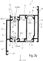
- FIG. 2a an inventive composite profile 4 is shown.
- This composite profile 4 can be used as a sash profile as part of a sash 2 or window frame 3 for doors 1, windows or other components, so that the following description refers equally to sash profiles and frame profiles.
- a composite profile 4 with two metallic outer profiles 12, 14 and a metallic center profile 16 will be described purely by way of example.
- the composite profile 4 can also be constructed without a metallic center profile 16, so that in this case the two metallic outer profiles 12, 14 via a Isoliersteradee connected to each other.
- such an alternative described construction of a composite profile 4 with two metallic outer profiles 12, 14 is more common than the structure with a metallic center profile 16th
- the composite profile 4 has a first metal profile, an outer profile 12, in which here at least one hollow chamber 13 is formed, and a second metallic outer profile 14, in which also preferably at least one hollow chamber 15 is formed. Between the two metal profiles 12 and 14, a third metal profile, a central profile 16, is arranged, in which also preferably at least one hollow chamber 17 is formed.
- the metallic profiles 12, 14, 16 may alternatively be designed without pronounced hollow chambers 13, 15, 17 or have a plurality of hollow chambers.
- the first metallic outer profile 12 is connected to the metallic center profile 16 via at least one or more first insulating webs (aligned parallel here) 18. These insulating webs 18 between the first metallic outer profile 12 and the metallic center profile 16 form a first insulating land zone I or plane.
- the second metallic outer profile 14 is also connected to the metallic center profile 16 via at least one or more second (parallel here) insulating bars 19.
- the insulating webs 19 between the second metallic outer profile 14 and the metallic center section 16 form a second insulating land zone II or plane.
- the first and second insulating webs 18, 19 have here, by way of example, no hollow chamber.
- the insulating webs 18, 19 but also have one or more hollow chambers or the first or the respective second insulating webs 18, 19 may be summarized by transverse webs to a kind of parent insulating.
- the insulating webs 18, 19 of the Isolierstegzonen I, II are here-purely exemplary- in a plane. Alternatively, it is also possible that the insulating webs 18, 19 of the Isolierstegzonen I, II are each arranged vertically and or horizontally offset from one another. Likewise, a diagonal orientation of the insulating webs 18, 19 is possible.
- the first and second metallic outer profile 12 and 14 and the metallic center profile 16 are preferably made as extruded aluminum profiles. Alternatively, the production is also possible from a different material such as steel and / or another manufacturing method.
- the insulating webs 18 and 19 are made of a plastic material, such as plastic. Polyamides (PA66, PA6, PPA), polyester (PET, PBT), polyolefins (PP) or polyvinyl chloride (PVC) produced, so that in each case a substantial thermal separation between the metal profiles 12, 14, 16 is achieved.
- the insulating webs 18 and 19 are web-shaped in cross-section and have thickened end portions 20.
- each of the end portions 20 engages in a corresponding groove 21 of each one of the metal profiles 12, 14, 16, wherein the groove walls, the thickened end portions 20 of the insulating bars 18, 19 in the x and y direction (see coordinate system in Fig. 2a ) preferably engage positively.
- the respective end portion 20 preferably has a trapezoidal or triangular or wedge-shaped or L-shaped or rectangular cross-section.
- the respective groove 21 accordingly has a cross section with a corresponding cross section.
- the respective end portions 20 are fixed in the respective groove 21 by a forming process and / or are fixed with a wire 22, having an outer structure, such as a knurling, which the shear strength in the profile direction (z-direction according to the coordinate system in Fig. 2a ) elevated.
- the end sections can also be inserted into the groove 21 with a suitable joining method without wire or the like.
- the second insulating land zone II has the second insulating webs 19 whose respective end sections 20 are positively and non-positively connected to the respective groove 21, so that in each case one also in particular in the z direction (cf., coordinate system in FIG. ) or in a direction orthogonal to the cross-sectional plane of the composite profile 4 shear-resistant connection between the second insulating webs 19 and the adjacent outer and middle metallic Subprofiles 14, 16 results.
- This connection is also referred to below as a shear-resistant design of one of the two - here the second - Isolierstegzonen. It offers a shear strength against the forces occurring as a result of dilatation on a window or door or the like.
- the shear strength of the other -here the first-Isolierstegzone I is in contrast lower than that of the first insulating land zone II in all variants. It is chosen such that a displacement of at least two elements in the Isolierstegzone relative to each other due to dilation is possible.
- the Isolierstegzone I lower shear strength in the installed state of a window or a door 1 to a building outside, since here the temperature differences are greater than on the inside of the building, so that here the lower shear resistance to compensate for dilation effects is particularly important.
- towards the interior side is preferably the Isolierstegzone with increased shear resistance. This variant of the invention is particularly advantageous. However, it is also conceivable to provide the Isolierstegzone higher shear strength to the room outside.
- Fig. 2a The invention is based on the in Fig. 2a respectively.
- Fig. 2b illustrated variant is not limited, but also on a composite profile 4 feasible, in which only two metal profiles 12, 14 (inner profile and outer profile) are connected via a single insulating land zone with one or more insulating webs 18.
- insulating webs 18 of the first insulating land zone I between the first metallic outer profile 12 and the metallic middle section 16 form a separation zone between the respective insulating web 18 and here the first outer profile 12, in which a sliding slide allows a relative movement.
- the separation zone can also be formed between the insulating web 18 and the second metal outer profile 14 or the center profile 16.
- the insulating web 18 is in y- and x-direction (relative to the coordinate system in Fig. 2a ) positively connected by a Kederharm with the first metallic outer profile 12.
- the insulating web 18 has a Kederwulst 24 and a Kederfahne 25.
- the first metallic outer profile 12 has a groove 26 with a corresponding cross-sectional geometry, so that the Kederwulst 24 in the groove 26 engages and the Kederfahne 25 is led out of the groove 26.
- a sliding guide is formed.
- the shear strength in the sliding guide orthogonal to the cross-sectional plane of the composite profile may, but need not go to zero.
- Such a sliding guide is colloquially referred to as a "non-detachable connection”.
- the functional element 27 is received in a groove 28, which is formed here by a circular recess / gradation of the insulating web 18 and the edge of the first metallic outer profile 12.
- the functional element 27 is shaped correspondingly and preferably has an excess with respect to the groove 28.
- the functional element 27 is arranged in an embodiment of the invention in different ways, as shown in the following figures, ie in a separation zone between the insulating web 18 and a metal profile 12, 14, 16 in a non-impact design.
- separation zone is understood to mean that the functional element 27 does not have to be arranged parallel to or next to the sliding guide, as shown purely by way of example below, so that a quasi-continuous dividing line results, but also arranged in this way may be that results in a dividing line, which extends kinked one or more times by 90 °, so that a separation zone is formed through which the dividing line passes.
- the functional element 27 is designed and arranged such that it compensates for tolerances of the non-thrust connection and / or influences the shear strength by appropriately selected coefficients of friction or by appropriate design of friction surfaces and / or a spring effect or thereby a force on the opposite sections of the insulating web exercises.
- the functional element 27 has a movement-inhibiting effect on the insulating web 18 in the separating zone.
- a movement-inhibiting force is indicated at 29 (see Fig. 6 ), wherein this force 29 is variably adjustable and can be deliberately adjusted in retrospect, in particular by different functional elements 27 to compensate for tolerances and to adjust the shear strength.
- the functional element 27 has lateral functional surfaces 31 and 32, which correspond geometrically with the groove 28, which are formed by the insulating web 18 and by the first metallic outer profile 12.
- the size and design of the surface and the surface texture, in particular the Reibbeihong can also be adjusted as needed.
- the coefficients of friction are also set via the geometric shape of the Kederwulst '24 and the groove 26 and their contact surfaces 30.
- connection With respect to the z-direction (see Coordinate system in Fig. 2a ), the connection is therefore thrustless - ie reduced thrust relative to a shear-resistant connection - executed.
- the functional element 27 can be made of different materials with different surfaces. Material pairings between the insulating web 18 or the metal profile 12, 14, 16 and the functional element 27 with defined frictional properties are particularly preferred. Among the preferred material pairings are material pairings of all types with the same friction parameters, since tolerances and coefficients of friction are simply matched to one another here. Preferably, PA / PA or Al / Al are used as material pairings. However, it may also be advantageous to use material pairings with significantly different modulus of elasticity between the two materials, as well as different surface structures in both components, resulting in different friction coefficients. Particularly preferably, the functional element is made of an elastomer, such as EPDM or a thermoplastic, such as PVC.
- a metallic functional element 27 has proved to be advantageous, which by virtue of its geometric shape with respect to its cross-sectional geometry can likewise exert spring-elastic forces on the insulating web 18 or on the metal profile 12, 14, 16.
- the surfaces of the groove 28 and the functional surfaces 31, 32 of the functional element 27 may also be roughened to produce a desired coefficient of friction with a corresponding mating surface.
- a (elastic) functional element 27 Another advantage of a (elastic) functional element 27 is that the dividing line is securely sealed against penetrating liquid, in particular paint during painting or dust. When applying paint in the powder coating process, this can penetrate into the dividing line of the sliding guide, whereby the sliding guide is at least partially blocked.
- the insulating webs 18 of the first insulating land zone I between the first metallic outer profile 14 and the metallic center section 16 have two insulating web sections or partial sections 18a, 18b or parts which are movable relative to one another.
- a separating zone is formed between the sections 18a, b, in which a sliding-smooth sliding guide allows a relative movement.
- cross-connection webs are formed between the sections of the insulating webs, which in turn are formed such that the sections are movable relative to each other (not shown).
- the two sections 18a, b of the insulating webs 18 are in the y- and x-direction (relative to the coordinate system in Fig. 2 ) positively connected by a Kederharm.
- a first section 18a of the insulating web 18 has a Kederwulst 24 and a Kederfahne 25.
- the other, second section 18b has a groove 26 with corresponding cross-sectional geometry, so that the Kederwulst 24 engages in the groove 26 and the Kederfahne 25 is led out of the groove 26.
- a sliding guide is formed.
- the shear strength in the Slide can orthogonal to the cross-sectional plane of the composite profile, but must not go to zero.
- Such a sliding guide is colloquially referred to as a "non-detachable connection”.
- the insulating web 18 - formed here with a rectangular cross section - functional element 27.
- the functional element 27 is accommodated in the groove 28, which is formed here by a rectangular recess / stepping of the first section of the insulating web 18 and the edge of the second section of the insulating web 18.
- the functional element is shaped correspondingly and preferably has an excess with respect to the groove 28.
- the functional element 27 is arranged in an embodiment of the invention in different ways, as shown in the following figures, ie in a separation zone between sections of the insulating bar 18 in schubweicher or thrustless design.
- the functional element 27 has a movement-inhibiting effect on the insulating strip sections 18a, b in the separating zone.
- a movement-inhibiting force is indicated at 29 (see Fig. 3 ), wherein this force 29 is variably adjustable and can be deliberately adjusted in retrospect, in particular by different functional elements 27 to compensate for tolerances and to adjust the shear strength.
- the functional element 27 has lateral functional surfaces 31 and 32 which correspond geometrically with the groove 28, which are formed by the two sections of the insulating web 18.
- the size and design of the surface and the surface texture, in particular the coefficient of friction, can also be adjusted as needed become.
- the coefficients of friction are also set via the geometric shape of the Kederwulst '24 and the groove 26 and their contact surfaces 30.
- connection With respect to the z-direction (see Coordinate system in Fig. 2b ), the connection is, however, therefore pushing soft or thrustless - ie reduced thrust relative to a shear-resistant connection - executed.
- Fig. 2b each one composite profile 4 created in the (here) first Isolierstegzone I each one with respect to the z-direction (see Fig. 2a 2b) relative to the other Isolierstegzone shear-reduced, in particular shear-soft or unobstructed, connection between the first metallic outer profile 12 and the insulating webs 18 and the metallic center section 16.
- the second insulating strip zone II in each case has a shear-resistant connection between the second metallic outer profile 14 and the insulating webs 19 or the metallic center profile 16.
- the composite profile 4 after Fig. 2a respectively.
- Fig. 2b Also in the second Isolierstegzone II a schubverringerte, ie shear-soft or unobstructed, connection between the second metallic outer profile 14 and the insulating webs 19 and the metallic center profile, while the first Isolierstegzone I relative to the shear-reduced shear-resistant (re) connection between the first metallic Has outer profile 12 and the insulating webs 18 and the metallic center section 16.
- a composite profile 4 which can compensate for temperature-induced deformations by a shear-soft or unobstructed connection of one of the metallic outer profiles 12, 14 and the respective insulating bars 18, 19 or with the metallic center section 16 and, surprisingly, a composite profile 4 with a high area moment of inertia or area momentum of the 2nd degree. It is also conceivable that the composite profile 4 in both Isolierstegzonen I, II with respect to the z-direction (see Fig. 2a respectively. Fig. 2b ) each have a shear-soft or unobstructed connection of the metallic outer profiles 12, 14 and the respective insulating bars 18, 19 or with the metallic center profile 16.
- Fig. 2b is shown that the first metallic outer profile 12 is separated from the metallic center profile 16 preferably via a hollow chamber 33 which is formed in the first insulating land zone I between the two first insulating bars 18 and the adjacent metal profiles, while the metallic center section 16 of the second metallic External profile 14 is separated by a hollow chamber 34 which is located in the second insulating land zone II between the second insulating webs 19 and the adjacent metal profiles.
- a plurality of hollow chambers 13, 33, 17, 34 and 15 are formed, which ensure good thermal insulation.
- the two metallic outer profiles 12, 14 have on each opposite sides outwardly projecting webs 35 and 36, wherein at the end of the web 35 a groove 37 for receiving a seal and on the web 36, a further groove 38 is provided for receiving a seal.
- Fig. 4 shows an insulating web 18 of a composite profile 4 according to the invention with a functional element 27 which is positively inserted, but with excess, between the two sections of the insulating web 18 is inserted.
- the groove 28 is here in each case approximately circular segment-shaped in cross section in the two adjoining isolierstegabroughen 18a, b formed.
- Such a designed functional element 27 can be easily, even later according to the requirements, on and removed.
- the functional element 27 exerts the force 29, which acts on the sliding guide movement inhibiting.
- an integrally molded web on the one metal profile and / or the other metal profile cover the insulating profile 18 and, for example, define a groove, which is provided for receiving the functional element 27 in the insulating web, so that the functional element 27 is additionally secured against falling out (not shown here).
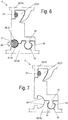
- Fig. 5 shows an embodiment of the invention after Fig. 2a , in which the functional element 27 is inserted between one of the metallic sub-profiles 12, 14, 16 and a preferably integral safety web 18.
- the insulating bar 18 in an advantageous manner compared to the embodiments according to 2b to Fig. 4 made stiffer, whereby the second moment of area or moment of area of the composite profile 4 according to the invention is increased accordingly and so by the composite profile 4 larger forces can be transmitted.
- Fig. 5 To Fig. 5 is a gradation / groove 28 in which a metallic partial profile 12, 16 is formed.
- the functional element 27 is inserted here with rectangular cross-section so that it protrudes slightly in the direction of the insulating bar 18.
- the functional element 27 exerts the force 29, which acts on the sliding guide - now arranged between metal section 12 and 16 and insulating web 18 - tolerance-compensating and movement-inhibiting.
- Fig. 6 shows the insulating web 18 of a composite profile 4 according to the invention Fig. 2a , which is provided with the functional element 27, which is set form-fitting, but with excess, between the insulating bar 18 and the adjacent metal section 12 or 16.
- the groove 28 is here in each case a circular segment in cross-section in the two adjoining parts insulating web 18 and one of the adjacent metal profiles 12 or 16 is formed.
- Such a designed functional element 27 can be easily, even later according to the requirements, on and removed.
- Fig. 7 shows an insulating web 18 of a composite profile according to the invention 4.
- the functional element 27 (not shown here) is used with oversize in an undercut area or a groove 39, wherein the undercut area or the groove 39 across in the metal section 12, 16 and the adjacent Insulating ridge 18 is formed only in the assembled state of these elements.
- the functional element 27 again has an excess, so that it can exert the force 29 between the two parts, which preferably acts on the sliding guide.
- the functional element 27 can also form the foot 40 of a seal or another component (see Fig. 12 ).
- the clamping force or spring force 29 may optionally be adjusted within the insulating bar 18 in addition.
- the functional element 27 exerts the force 29, which acts on the sliding guide movement inhibiting.
- insulating web 18 is here -analog to the embodiments according to Fig. 2a .
- Fig. 4 to Fig. 7 - In an advantageous manner compared to the embodiments according to Fig. 2a to Fig. 4 made stiffer, creating the area moment of inertia or area moment 2nd order of the composite profile 4 according to the invention is increased accordingly and so by the composite profile 4 larger forces are transferable.
- the insulating web has a comparatively short length between the metallic sub-profiles 12, 14, 16.
- the insulating bar 18 has an undercut groove 39, which is here purely exemplary-oriented to the frame and the other functional elements such as seals, or their feet 40, heat-insulating wedges, glass blocks, more profile strips is available.
- a functional element 27 according to the invention is arranged parallel thereto.
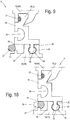
- Fig. 9 is a variant of the composite profile 4 in the manner of Fig. 8 shown.
- the functional element 27 is integrally connected via a film hinge 44 with the insulating web 18.
- the functional element 27 additionally assumes the function of a seal here.
- the insulating web 18 with the integrally connected functional element 27 is preferably made of two different plastic materials by a co-extrusion process.
- Material pairings between the insulating web 18 and the functional element 27 or between the respective metallic partial profile 12, 14, 16 and the functional element 27 with defined friction properties are particularly preferred.
- the preferred material pairings include material combinations of all types with significantly different modulus of elasticity between the two respective materials, as well as different surface structures in the respective components, resulting in each case different friction coefficients.
- the surfaces of the groove 28 and the functional surfaces 31, 32 of the functional element 27 may also be roughened to produce a desired coefficient of friction with a corresponding mating surface.
- Fig. 10 is the embodiment according to Fig. 9 shown in the assembled state of the functional element 27.
- the functional element 27 is arranged parallel to it in the plane of the thrustless or thrust-free connection.
- the functional element engages 27 by a snap, snap or clip connection in a groove 28, which is formed here by the insulating web 18 and a recess in the respective metallic part profile 12, 14, 16.
- the snap-action, latching or clip connection can also be formed between the insulating web 18 and the functional element 27, separately or in addition to the film hinge 44 (not shown).
- the functional element 27 also fulfills the function of a seal here.
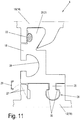
- Fig. 11 is a further, particularly preferred embodiment of a composite profile 4 according to the invention Fig. 8 to Fig. 10 shown.
- the functional element 27 in the form of a web of the first metallic outer profile 12 and the metallic center section 16 is formed.
- the web or the functional element 27 is brought to the insulating web 18 after inserting the insulating strip so that the functional element 27 can compensate for tolerances.
- the functional element 27 exerts the force 29, which acts on the sliding guide movement inhibiting.
- the function of the functional element 27 is integrated into one of the metal profiles 12, 14, 16 and can advantageously by a forming process, through which a positive connection between the insulating webs 18th , 19 and the metal profiles 12, 14, 16 is produced with.
- the assembly process of a separate functional element 27 is saved, which has an advantageous effect on the production costs of such a composite profile 4 according to the invention.
- Fig. 12 is a further embodiment of a composite profile according to the invention 4 according to the embodiment in Fig. 8 respectively.
- Fig. 9 respectively.
- Fig. 10 shown.
- the undercut groove 39 of the insulating bar 18 here is purely exemplary a folding element 45 is inserted with a kind of snap connection.
- the foot 40 of the folding element 45 engages in the undercut groove 39 of the insulating bar 18 a.
- the folding element 45 also has a sealing lip 46.
- the folding element 45 has an integrally worked functional element 27, which also engages via a kind of snap connection in a groove 28 which is formed here in the region of the separation zone by the insulating web 18 and a recess of the respective metallic sub-profile 12, 14, 16.
- the functional surfaces 31, 32 of the functional element 27 are here wedge-shaped, so that the groove 28 here also has an undercut cross-sectional geometry.
- the folding element 45 is preferably made of two different plastic materials by a co-extrusion process.
- Material pairings between the insulating web 18 and the functional element 27 or between the respective metallic partial profile 12, 14, 16 and the functional element 27 with defined friction properties are particularly preferred.
- the preferred material pairings include material combinations of all types with significantly different modulus of elasticity between the two respective materials, as well as different surface structures in the respective components, resulting in each case different friction coefficients.
- the surfaces of the groove 28 and the functional surfaces 31, 32 of the functional element 27 may also be roughened to produce a desired coefficient of friction with a corresponding mating surface.
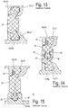
- the composite profile after Fig. 13 Each has a shear-resistant insulating web 19.
- composite profile 4 shown also has a Kedertell, wherein the Kedernut here in a metallic part profile 12, 14, 16 is located.
- the composite profile also has no Eistell options regarding the desired or required coefficients of friction between the insulating bar and the respective metallic partial profile, in particular no inventive functional element 27th
Landscapes
- Engineering & Computer Science (AREA)
- Civil Engineering (AREA)
- Structural Engineering (AREA)
- Wing Frames And Configurations (AREA)
Priority Applications (1)
| Application Number | Priority Date | Filing Date | Title |
|---|---|---|---|
| PL15720943T PL3140484T3 (pl) | 2014-05-05 | 2015-04-29 | Profil zespolony do drzwi, okien lub elementów elewacyjnych |
Applications Claiming Priority (3)
| Application Number | Priority Date | Filing Date | Title |
|---|---|---|---|
| DE102014106226.4A DE102014106226A1 (de) | 2014-05-05 | 2014-05-05 | Verbundprofil für Türen, Fenster oder Fassadenelemente |
| DE102014112131.7A DE102014112131A1 (de) | 2014-08-25 | 2014-08-25 | Verbundprofil für Türen, Fenster oder Fassadenelemente |
| PCT/EP2015/059388 WO2015169670A1 (de) | 2014-05-05 | 2015-04-29 | Verbundprofil für türen, fenster oder fassadenelemente |
Publications (2)
| Publication Number | Publication Date |
|---|---|
| EP3140484A1 EP3140484A1 (de) | 2017-03-15 |
| EP3140484B1 true EP3140484B1 (de) | 2019-01-02 |
Family
ID=53055022
Family Applications (1)
| Application Number | Title | Priority Date | Filing Date |
|---|---|---|---|
| EP15720943.8A Active EP3140484B1 (de) | 2014-05-05 | 2015-04-29 | Verbundprofil für türen, fenster oder fassadenelemente |
Country Status (3)
| Country | Link |
|---|---|
| EP (1) | EP3140484B1 (pl) |
| PL (1) | PL3140484T3 (pl) |
| WO (1) | WO2015169670A1 (pl) |
Families Citing this family (2)
| Publication number | Priority date | Publication date | Assignee | Title |
|---|---|---|---|---|
| DE102016119580A1 (de) * | 2016-10-13 | 2018-04-19 | Ensinger Gmbh | Kunststoffprofil für ein Metall-Kunststoff-Verbundprofil |
| GB2604579B (en) * | 2021-01-28 | 2025-02-05 | Garner Aluminium Extrusions Ltd | A window frame assembly |
Family Cites Families (5)
| Publication number | Priority date | Publication date | Assignee | Title |
|---|---|---|---|---|
| DE3343687A1 (de) * | 1983-11-30 | 1985-06-05 | Schweizerische Aluminium Ag, Chippis | Metall-rahmenkonstruktion fuer fenster oder tueren |
| DE19637858A1 (de) * | 1996-09-17 | 1998-04-02 | Schueco Int Kg | Wärmegedämmtes Verbundprofil für Türen, Fenster oder Fassaden |
| DE19956415C1 (de) * | 1999-11-24 | 2001-03-01 | Caprano & Brunnhofer | Isolierprofil für Türrahmen, Fensterrahmen oder dergleichen Verbundteile |
| DE10015986C2 (de) * | 2000-03-31 | 2002-08-01 | Schueco Int Kg | Verbundprofil und Verfahren zur Herstellung eines Verbundprofils |
| DE102013204693A1 (de) * | 2012-03-19 | 2013-09-19 | Harald Schulz | Dämmsteg für wärmegedämmte Metall-Kunststoff-Verbundprofile mit über der Dämmsteglänge veränderlicher Schubtragfähigkeit sowie wärmegedämmtes Verbundprofil |
-
2015
- 2015-04-29 EP EP15720943.8A patent/EP3140484B1/de active Active
- 2015-04-29 WO PCT/EP2015/059388 patent/WO2015169670A1/de not_active Ceased
- 2015-04-29 PL PL15720943T patent/PL3140484T3/pl unknown
Non-Patent Citations (1)
| Title |
|---|
| None * |
Also Published As
| Publication number | Publication date |
|---|---|
| WO2015169670A1 (de) | 2015-11-12 |
| PL3140484T3 (pl) | 2019-08-30 |
| EP3140484A1 (de) | 2017-03-15 |
Similar Documents
| Publication | Publication Date | Title |
|---|---|---|
| EP1555376A1 (de) | Verbundprofilanordnung | |
| DE202010008921U1 (de) | Mitteldichtung für hoch wärmegedämmte Fenster oder Türen | |
| DE2608325B2 (de) | Mehrteiliger, waermegedaemmter metallprofilstab zum befestigen von wand- und fensterelementen | |
| EP1251236B1 (de) | Industrietor, doppelwandige Lamelle für ein Industrietor sowie Verfahren zur Herstellung einer derartigen Lamelle | |
| EP3246505B1 (de) | Verbundprofil für türen, fenster oder fassadenelemente | |
| DE1509553A1 (de) | Fensterkonstruktion | |
| EP3140484B1 (de) | Verbundprofil für türen, fenster oder fassadenelemente | |
| EP2363567B1 (de) | Rahmen eines Kunststofffensters oder einer Kunststofftür | |
| EP2530230B1 (de) | Isoliersteg für Fenster- und Türrahmen | |
| EP3015635B1 (de) | Verbundprofil für türen, fenster oder fassadenelemente | |
| EP3140483B1 (de) | Verbundprofil für türen, fenster oder fassadenelemente | |
| DE102014112128A1 (de) | Verbundprofil für Türen, Fenster oder Fassadenelemente | |
| EP2754839A1 (de) | Rahmen oder T-Verbindung und Verfahren zur Montage eines Rahmens oder einer T-Verbindung | |
| DE20100618U1 (de) | Rahmenprofil | |
| DE102014112145A1 (de) | Verbundprofil für Türen, Fenster oder Fassadenelemente | |
| WO1999067495A1 (de) | Verbindung für kunststoffhohlprofile | |
| DE102011008765A1 (de) | Profilanordnung, Rahmen und Rahmenanordnung | |
| EP3574176B1 (de) | Führungsschiene zur führung von rollladen-, sonnenschutzanlagen oder dergleichen sowie verfahren zu ihrer herstellung | |
| DE102014112131A1 (de) | Verbundprofil für Türen, Fenster oder Fassadenelemente | |
| EP3196395B1 (de) | Tür mit einem griffprofil | |
| DE10034889B4 (de) | Spreizglashalter | |
| EP2942468B1 (de) | Verbundprofil für türen, fenster oder fassadenelemente | |
| DE102019113123A1 (de) | Wärmedämmprofilanordnung | |
| DE29701029U1 (de) | Wärmegedämmtes Verbundprofil | |
| DE102014112092A1 (de) | Tür, Fenster oder Fassadenelement mit einem Eckverbinder |
Legal Events
| Date | Code | Title | Description |
|---|---|---|---|
| STAA | Information on the status of an ep patent application or granted ep patent |
Free format text: STATUS: THE INTERNATIONAL PUBLICATION HAS BEEN MADE |
|
| PUAI | Public reference made under article 153(3) epc to a published international application that has entered the european phase |
Free format text: ORIGINAL CODE: 0009012 |
|
| STAA | Information on the status of an ep patent application or granted ep patent |
Free format text: STATUS: REQUEST FOR EXAMINATION WAS MADE |
|
| 17P | Request for examination filed |
Effective date: 20160926 |
|
| AK | Designated contracting states |
Kind code of ref document: A1 Designated state(s): AL AT BE BG CH CY CZ DE DK EE ES FI FR GB GR HR HU IE IS IT LI LT LU LV MC MK MT NL NO PL PT RO RS SE SI SK SM TR |
|
| AX | Request for extension of the european patent |
Extension state: BA ME |
|
| DAV | Request for validation of the european patent (deleted) | ||
| DAX | Request for extension of the european patent (deleted) | ||
| GRAP | Despatch of communication of intention to grant a patent |
Free format text: ORIGINAL CODE: EPIDOSNIGR1 |
|
| STAA | Information on the status of an ep patent application or granted ep patent |
Free format text: STATUS: GRANT OF PATENT IS INTENDED |
|
| INTG | Intention to grant announced |
Effective date: 20180720 |
|
| GRAS | Grant fee paid |
Free format text: ORIGINAL CODE: EPIDOSNIGR3 |
|
| GRAA | (expected) grant |
Free format text: ORIGINAL CODE: 0009210 |
|
| STAA | Information on the status of an ep patent application or granted ep patent |
Free format text: STATUS: THE PATENT HAS BEEN GRANTED |
|
| AK | Designated contracting states |
Kind code of ref document: B1 Designated state(s): AL AT BE BG CH CY CZ DE DK EE ES FI FR GB GR HR HU IE IS IT LI LT LU LV MC MK MT NL NO PL PT RO RS SE SI SK SM TR |
|
| REG | Reference to a national code |
Ref country code: GB Ref legal event code: FG4D Free format text: NOT ENGLISH |
|
| REG | Reference to a national code |
Ref country code: CH Ref legal event code: EP Ref country code: AT Ref legal event code: REF Ref document number: 1084590 Country of ref document: AT Kind code of ref document: T Effective date: 20190115 |
|
| REG | Reference to a national code |
Ref country code: DE Ref legal event code: R096 Ref document number: 502015007517 Country of ref document: DE |
|
| REG | Reference to a national code |
Ref country code: IE Ref legal event code: FG4D Free format text: LANGUAGE OF EP DOCUMENT: GERMAN |
|
| REG | Reference to a national code |
Ref country code: NL Ref legal event code: MP Effective date: 20190102 |
|
| REG | Reference to a national code |
Ref country code: LT Ref legal event code: MG4D |
|
| PG25 | Lapsed in a contracting state [announced via postgrant information from national office to epo] |
Ref country code: NL Free format text: LAPSE BECAUSE OF FAILURE TO SUBMIT A TRANSLATION OF THE DESCRIPTION OR TO PAY THE FEE WITHIN THE PRESCRIBED TIME-LIMIT Effective date: 20190102 |
|
| PG25 | Lapsed in a contracting state [announced via postgrant information from national office to epo] |
Ref country code: ES Free format text: LAPSE BECAUSE OF FAILURE TO SUBMIT A TRANSLATION OF THE DESCRIPTION OR TO PAY THE FEE WITHIN THE PRESCRIBED TIME-LIMIT Effective date: 20190102 Ref country code: SE Free format text: LAPSE BECAUSE OF FAILURE TO SUBMIT A TRANSLATION OF THE DESCRIPTION OR TO PAY THE FEE WITHIN THE PRESCRIBED TIME-LIMIT Effective date: 20190102 Ref country code: PT Free format text: LAPSE BECAUSE OF FAILURE TO SUBMIT A TRANSLATION OF THE DESCRIPTION OR TO PAY THE FEE WITHIN THE PRESCRIBED TIME-LIMIT Effective date: 20190502 Ref country code: FI Free format text: LAPSE BECAUSE OF FAILURE TO SUBMIT A TRANSLATION OF THE DESCRIPTION OR TO PAY THE FEE WITHIN THE PRESCRIBED TIME-LIMIT Effective date: 20190102 Ref country code: NO Free format text: LAPSE BECAUSE OF FAILURE TO SUBMIT A TRANSLATION OF THE DESCRIPTION OR TO PAY THE FEE WITHIN THE PRESCRIBED TIME-LIMIT Effective date: 20190402 Ref country code: LT Free format text: LAPSE BECAUSE OF FAILURE TO SUBMIT A TRANSLATION OF THE DESCRIPTION OR TO PAY THE FEE WITHIN THE PRESCRIBED TIME-LIMIT Effective date: 20190102 |
|
| PG25 | Lapsed in a contracting state [announced via postgrant information from national office to epo] |
Ref country code: BG Free format text: LAPSE BECAUSE OF FAILURE TO SUBMIT A TRANSLATION OF THE DESCRIPTION OR TO PAY THE FEE WITHIN THE PRESCRIBED TIME-LIMIT Effective date: 20190402 Ref country code: GR Free format text: LAPSE BECAUSE OF FAILURE TO SUBMIT A TRANSLATION OF THE DESCRIPTION OR TO PAY THE FEE WITHIN THE PRESCRIBED TIME-LIMIT Effective date: 20190403 Ref country code: IS Free format text: LAPSE BECAUSE OF FAILURE TO SUBMIT A TRANSLATION OF THE DESCRIPTION OR TO PAY THE FEE WITHIN THE PRESCRIBED TIME-LIMIT Effective date: 20190502 Ref country code: HR Free format text: LAPSE BECAUSE OF FAILURE TO SUBMIT A TRANSLATION OF THE DESCRIPTION OR TO PAY THE FEE WITHIN THE PRESCRIBED TIME-LIMIT Effective date: 20190102 Ref country code: LV Free format text: LAPSE BECAUSE OF FAILURE TO SUBMIT A TRANSLATION OF THE DESCRIPTION OR TO PAY THE FEE WITHIN THE PRESCRIBED TIME-LIMIT Effective date: 20190102 Ref country code: RS Free format text: LAPSE BECAUSE OF FAILURE TO SUBMIT A TRANSLATION OF THE DESCRIPTION OR TO PAY THE FEE WITHIN THE PRESCRIBED TIME-LIMIT Effective date: 20190102 |
|
| REG | Reference to a national code |
Ref country code: DE Ref legal event code: R097 Ref document number: 502015007517 Country of ref document: DE |
|
| PG25 | Lapsed in a contracting state [announced via postgrant information from national office to epo] |
Ref country code: CZ Free format text: LAPSE BECAUSE OF FAILURE TO SUBMIT A TRANSLATION OF THE DESCRIPTION OR TO PAY THE FEE WITHIN THE PRESCRIBED TIME-LIMIT Effective date: 20190102 Ref country code: RO Free format text: LAPSE BECAUSE OF FAILURE TO SUBMIT A TRANSLATION OF THE DESCRIPTION OR TO PAY THE FEE WITHIN THE PRESCRIBED TIME-LIMIT Effective date: 20190102 Ref country code: DK Free format text: LAPSE BECAUSE OF FAILURE TO SUBMIT A TRANSLATION OF THE DESCRIPTION OR TO PAY THE FEE WITHIN THE PRESCRIBED TIME-LIMIT Effective date: 20190102 Ref country code: EE Free format text: LAPSE BECAUSE OF FAILURE TO SUBMIT A TRANSLATION OF THE DESCRIPTION OR TO PAY THE FEE WITHIN THE PRESCRIBED TIME-LIMIT Effective date: 20190102 Ref country code: AL Free format text: LAPSE BECAUSE OF FAILURE TO SUBMIT A TRANSLATION OF THE DESCRIPTION OR TO PAY THE FEE WITHIN THE PRESCRIBED TIME-LIMIT Effective date: 20190102 Ref country code: SK Free format text: LAPSE BECAUSE OF FAILURE TO SUBMIT A TRANSLATION OF THE DESCRIPTION OR TO PAY THE FEE WITHIN THE PRESCRIBED TIME-LIMIT Effective date: 20190102 |
|
| PLBE | No opposition filed within time limit |
Free format text: ORIGINAL CODE: 0009261 |
|
| STAA | Information on the status of an ep patent application or granted ep patent |
Free format text: STATUS: NO OPPOSITION FILED WITHIN TIME LIMIT |
|
| PG25 | Lapsed in a contracting state [announced via postgrant information from national office to epo] |
Ref country code: SM Free format text: LAPSE BECAUSE OF FAILURE TO SUBMIT A TRANSLATION OF THE DESCRIPTION OR TO PAY THE FEE WITHIN THE PRESCRIBED TIME-LIMIT Effective date: 20190102 |
|
| REG | Reference to a national code |
Ref country code: CH Ref legal event code: PL |
|
| 26N | No opposition filed |
Effective date: 20191003 |
|
| GBPC | Gb: european patent ceased through non-payment of renewal fee |
Effective date: 20190429 |
|
| PG25 | Lapsed in a contracting state [announced via postgrant information from national office to epo] |
Ref country code: MC Free format text: LAPSE BECAUSE OF FAILURE TO SUBMIT A TRANSLATION OF THE DESCRIPTION OR TO PAY THE FEE WITHIN THE PRESCRIBED TIME-LIMIT Effective date: 20190102 Ref country code: LU Free format text: LAPSE BECAUSE OF NON-PAYMENT OF DUE FEES Effective date: 20190429 |
|
| PG25 | Lapsed in a contracting state [announced via postgrant information from national office to epo] |
Ref country code: GB Free format text: LAPSE BECAUSE OF NON-PAYMENT OF DUE FEES Effective date: 20190429 Ref country code: CH Free format text: LAPSE BECAUSE OF NON-PAYMENT OF DUE FEES Effective date: 20190430 Ref country code: LI Free format text: LAPSE BECAUSE OF NON-PAYMENT OF DUE FEES Effective date: 20190430 |
|
| PG25 | Lapsed in a contracting state [announced via postgrant information from national office to epo] |
Ref country code: SI Free format text: LAPSE BECAUSE OF FAILURE TO SUBMIT A TRANSLATION OF THE DESCRIPTION OR TO PAY THE FEE WITHIN THE PRESCRIBED TIME-LIMIT Effective date: 20190102 |
|
| PG25 | Lapsed in a contracting state [announced via postgrant information from national office to epo] |
Ref country code: TR Free format text: LAPSE BECAUSE OF FAILURE TO SUBMIT A TRANSLATION OF THE DESCRIPTION OR TO PAY THE FEE WITHIN THE PRESCRIBED TIME-LIMIT Effective date: 20190102 |
|
| PG25 | Lapsed in a contracting state [announced via postgrant information from national office to epo] |
Ref country code: IE Free format text: LAPSE BECAUSE OF NON-PAYMENT OF DUE FEES Effective date: 20190429 |
|
| PG25 | Lapsed in a contracting state [announced via postgrant information from national office to epo] |
Ref country code: CY Free format text: LAPSE BECAUSE OF FAILURE TO SUBMIT A TRANSLATION OF THE DESCRIPTION OR TO PAY THE FEE WITHIN THE PRESCRIBED TIME-LIMIT Effective date: 20190102 |
|
| REG | Reference to a national code |
Ref country code: AT Ref legal event code: MM01 Ref document number: 1084590 Country of ref document: AT Kind code of ref document: T Effective date: 20200429 |
|
| PG25 | Lapsed in a contracting state [announced via postgrant information from national office to epo] |
Ref country code: MT Free format text: LAPSE BECAUSE OF FAILURE TO SUBMIT A TRANSLATION OF THE DESCRIPTION OR TO PAY THE FEE WITHIN THE PRESCRIBED TIME-LIMIT Effective date: 20190102 Ref country code: HU Free format text: LAPSE BECAUSE OF FAILURE TO SUBMIT A TRANSLATION OF THE DESCRIPTION OR TO PAY THE FEE WITHIN THE PRESCRIBED TIME-LIMIT; INVALID AB INITIO Effective date: 20150429 |
|
| PG25 | Lapsed in a contracting state [announced via postgrant information from national office to epo] |
Ref country code: AT Free format text: LAPSE BECAUSE OF NON-PAYMENT OF DUE FEES Effective date: 20200429 |
|
| PG25 | Lapsed in a contracting state [announced via postgrant information from national office to epo] |
Ref country code: MK Free format text: LAPSE BECAUSE OF FAILURE TO SUBMIT A TRANSLATION OF THE DESCRIPTION OR TO PAY THE FEE WITHIN THE PRESCRIBED TIME-LIMIT Effective date: 20190102 |
|
| P01 | Opt-out of the competence of the unified patent court (upc) registered |
Effective date: 20230814 |
|
| PGFP | Annual fee paid to national office [announced via postgrant information from national office to epo] |
Ref country code: PL Payment date: 20250314 Year of fee payment: 11 |
|
| PGFP | Annual fee paid to national office [announced via postgrant information from national office to epo] |
Ref country code: DE Payment date: 20250317 Year of fee payment: 11 |
|
| PGFP | Annual fee paid to national office [announced via postgrant information from national office to epo] |
Ref country code: IT Payment date: 20250430 Year of fee payment: 11 Ref country code: BE Payment date: 20250422 Year of fee payment: 11 |
|
| PGFP | Annual fee paid to national office [announced via postgrant information from national office to epo] |
Ref country code: FR Payment date: 20250415 Year of fee payment: 11 |