EP3138961A1 - Paving screed - Google Patents
Paving screed Download PDFInfo
- Publication number
- EP3138961A1 EP3138961A1 EP16189023.1A EP16189023A EP3138961A1 EP 3138961 A1 EP3138961 A1 EP 3138961A1 EP 16189023 A EP16189023 A EP 16189023A EP 3138961 A1 EP3138961 A1 EP 3138961A1
- Authority
- EP
- European Patent Office
- Prior art keywords
- eccentric
- eccentric shaft
- screed
- stroke
- tamper
- Prior art date
- Legal status (The legal status is an assumption and is not a legal conclusion. Google has not performed a legal analysis and makes no representation as to the accuracy of the status listed.)
- Granted
Links
Images


Classifications
-
- E—FIXED CONSTRUCTIONS
- E01—CONSTRUCTION OF ROADS, RAILWAYS, OR BRIDGES
- E01C—CONSTRUCTION OF, OR SURFACES FOR, ROADS, SPORTS GROUNDS, OR THE LIKE; MACHINES OR AUXILIARY TOOLS FOR CONSTRUCTION OR REPAIR
- E01C19/00—Machines, tools or auxiliary devices for preparing or distributing paving materials, for working the placed materials, or for forming, consolidating, or finishing the paving
- E01C19/004—Devices for guiding or controlling the machines along a predetermined path
-
- E—FIXED CONSTRUCTIONS
- E01—CONSTRUCTION OF ROADS, RAILWAYS, OR BRIDGES
- E01C—CONSTRUCTION OF, OR SURFACES FOR, ROADS, SPORTS GROUNDS, OR THE LIKE; MACHINES OR AUXILIARY TOOLS FOR CONSTRUCTION OR REPAIR
- E01C19/00—Machines, tools or auxiliary devices for preparing or distributing paving materials, for working the placed materials, or for forming, consolidating, or finishing the paving
- E01C19/22—Machines, tools or auxiliary devices for preparing or distributing paving materials, for working the placed materials, or for forming, consolidating, or finishing the paving for consolidating or finishing laid-down unset materials
- E01C19/30—Tamping or vibrating apparatus other than rollers ; Devices for ramming individual paving elements
- E01C19/34—Power-driven rammers or tampers, e.g. air-hammer impacted shoes for ramming stone-sett paving; Hand-actuated ramming or tamping machines, e.g. tampers with manually hoisted dropping weight
- E01C19/40—Power-driven rammers or tampers, e.g. air-hammer impacted shoes for ramming stone-sett paving; Hand-actuated ramming or tamping machines, e.g. tampers with manually hoisted dropping weight adapted to impart a smooth finish to the paving, e.g. tamping or vibrating finishers
- E01C19/407—Power-driven rammers or tampers, e.g. air-hammer impacted shoes for ramming stone-sett paving; Hand-actuated ramming or tamping machines, e.g. tampers with manually hoisted dropping weight adapted to impart a smooth finish to the paving, e.g. tamping or vibrating finishers with elements or parts partly or fully immersed in or penetrating into the material to act thereon, e.g. immersed vibrators or vibrating parts, kneading tampers, spaders
-
- B—PERFORMING OPERATIONS; TRANSPORTING
- B06—GENERATING OR TRANSMITTING MECHANICAL VIBRATIONS IN GENERAL
- B06B—METHODS OR APPARATUS FOR GENERATING OR TRANSMITTING MECHANICAL VIBRATIONS OF INFRASONIC, SONIC, OR ULTRASONIC FREQUENCY, e.g. FOR PERFORMING MECHANICAL WORK IN GENERAL
- B06B1/00—Methods or apparatus for generating mechanical vibrations of infrasonic, sonic, or ultrasonic frequency
- B06B1/10—Methods or apparatus for generating mechanical vibrations of infrasonic, sonic, or ultrasonic frequency making use of mechanical energy
- B06B1/16—Methods or apparatus for generating mechanical vibrations of infrasonic, sonic, or ultrasonic frequency making use of mechanical energy operating with systems involving rotary unbalanced masses
- B06B1/161—Adjustable systems, i.e. where amplitude or direction of frequency of vibration can be varied
- B06B1/162—Making use of masses with adjustable amount of eccentricity
- B06B1/164—Making use of masses with adjustable amount of eccentricity the amount of eccentricity being automatically variable as a function of the running condition, e.g. speed, direction
-
- E—FIXED CONSTRUCTIONS
- E01—CONSTRUCTION OF ROADS, RAILWAYS, OR BRIDGES
- E01C—CONSTRUCTION OF, OR SURFACES FOR, ROADS, SPORTS GROUNDS, OR THE LIKE; MACHINES OR AUXILIARY TOOLS FOR CONSTRUCTION OR REPAIR
- E01C19/00—Machines, tools or auxiliary devices for preparing or distributing paving materials, for working the placed materials, or for forming, consolidating, or finishing the paving
- E01C19/002—Apparatus for preparing and placing the materials and for consolidating or finishing the paving
-
- E—FIXED CONSTRUCTIONS
- E01—CONSTRUCTION OF ROADS, RAILWAYS, OR BRIDGES
- E01C—CONSTRUCTION OF, OR SURFACES FOR, ROADS, SPORTS GROUNDS, OR THE LIKE; MACHINES OR AUXILIARY TOOLS FOR CONSTRUCTION OR REPAIR
- E01C19/00—Machines, tools or auxiliary devices for preparing or distributing paving materials, for working the placed materials, or for forming, consolidating, or finishing the paving
- E01C19/22—Machines, tools or auxiliary devices for preparing or distributing paving materials, for working the placed materials, or for forming, consolidating, or finishing the paving for consolidating or finishing laid-down unset materials
- E01C19/30—Tamping or vibrating apparatus other than rollers ; Devices for ramming individual paving elements
- E01C19/34—Power-driven rammers or tampers, e.g. air-hammer impacted shoes for ramming stone-sett paving; Hand-actuated ramming or tamping machines, e.g. tampers with manually hoisted dropping weight
-
- E—FIXED CONSTRUCTIONS
- E01—CONSTRUCTION OF ROADS, RAILWAYS, OR BRIDGES
- E01C—CONSTRUCTION OF, OR SURFACES FOR, ROADS, SPORTS GROUNDS, OR THE LIKE; MACHINES OR AUXILIARY TOOLS FOR CONSTRUCTION OR REPAIR
- E01C19/00—Machines, tools or auxiliary devices for preparing or distributing paving materials, for working the placed materials, or for forming, consolidating, or finishing the paving
- E01C19/22—Machines, tools or auxiliary devices for preparing or distributing paving materials, for working the placed materials, or for forming, consolidating, or finishing the paving for consolidating or finishing laid-down unset materials
- E01C19/42—Machines for imparting a smooth finish to freshly-laid paving courses other than by rolling, tamping or vibrating
-
- E—FIXED CONSTRUCTIONS
- E01—CONSTRUCTION OF ROADS, RAILWAYS, OR BRIDGES
- E01C—CONSTRUCTION OF, OR SURFACES FOR, ROADS, SPORTS GROUNDS, OR THE LIKE; MACHINES OR AUXILIARY TOOLS FOR CONSTRUCTION OR REPAIR
- E01C19/00—Machines, tools or auxiliary devices for preparing or distributing paving materials, for working the placed materials, or for forming, consolidating, or finishing the paving
- E01C19/48—Machines, tools or auxiliary devices for preparing or distributing paving materials, for working the placed materials, or for forming, consolidating, or finishing the paving for laying-down the materials and consolidating them, or finishing the surface, e.g. slip forms therefor, forming kerbs or gutters in a continuous operation in situ
- E01C19/4833—Machines, tools or auxiliary devices for preparing or distributing paving materials, for working the placed materials, or for forming, consolidating, or finishing the paving for laying-down the materials and consolidating them, or finishing the surface, e.g. slip forms therefor, forming kerbs or gutters in a continuous operation in situ with tamping or vibrating means for consolidating or finishing, e.g. immersed vibrators, with or without non-vibratory or non-percussive pressing or smoothing means
- E01C19/4853—Apparatus designed for railless operation, e.g. crawler-mounted, provided with portable trackway arrangements
-
- E—FIXED CONSTRUCTIONS
- E01—CONSTRUCTION OF ROADS, RAILWAYS, OR BRIDGES
- E01C—CONSTRUCTION OF, OR SURFACES FOR, ROADS, SPORTS GROUNDS, OR THE LIKE; MACHINES OR AUXILIARY TOOLS FOR CONSTRUCTION OR REPAIR
- E01C23/00—Auxiliary devices or arrangements for constructing, repairing, reconditioning, or taking-up road or like surfaces
- E01C23/06—Devices or arrangements for working the finished surface; Devices for repairing or reconditioning the surface of damaged paving; Recycling in place or on the road
-
- E—FIXED CONSTRUCTIONS
- E01—CONSTRUCTION OF ROADS, RAILWAYS, OR BRIDGES
- E01C—CONSTRUCTION OF, OR SURFACES FOR, ROADS, SPORTS GROUNDS, OR THE LIKE; MACHINES OR AUXILIARY TOOLS FOR CONSTRUCTION OR REPAIR
- E01C2301/00—Machine characteristics, parts or accessories not otherwise provided for
- E01C2301/14—Extendable screeds
Definitions
- the invention relates to a screed according to the preamble of patent claim 1.
- the floating towed screed When installing a pavement made of bituminous or concrete material with a paver, the floating towed screed has to compact the paving as evenly as possible over the entire paving width and to create a closed, level structure.
- the compression unit for example a so-called tamper or a tamper and an unbalance vibrator, is intended to produce the highest possible constant and continuous over the lining thickness pre-compaction, so that different or varying coating thicknesses have no appreciable effect on the final compaction.
- the stroke and the frequency of the tampers influence the precompression and the floating behavior of the screed. The larger the stroke, the higher the pre-compression becomes and the deeper pre-compressed. The frequency can be individually adjusted infinitely.
- EP 0 493 664 A discloses the tamper frequency, for example, to adjust as a function of the installation speed. It is also expedient to adapt the tamper stroke of the lining thickness so that the screed incorporates the lowest possible positive angle. If the stroke is too large for the lining thickness, a negative angle of attack of the screed may result, which may lead to an open, cracked surface structure or uncontrollable leveling behavior of the screed, resulting in unevenness.
- the covering thickness is specified, for example, by adjusting the height of the traction points of the screed on the paver.
- the frequency and the installation speed must be adapted to each other. So far, the vote is individually chosen so that the screed incorporates the least possible positive angle.
- the installation speed determines the effect of the compacting unit on the surface.
- the installation speed should be selected so that the most constant possible material supply is ensured by the transport vehicles. Since the installation speed has a great influence on the precompression, it should be ensured that the screed incorporates a low positive angle of attack in order to ensure good planarity, ie the driven installation speed must allow good precompression.
- the stroke has hitherto been adjusted manually in several stages, whereby the installation operation must be interrupted in each case. However, each stroke is only a compromise because it fits only to a lining thickness. For example, a larger amount of built-in material is pre-compressed by the tamper bar due to an increase in stroke within the set lining thickness. To increase the pre-compression is also by increasing the frequency. In certain cases, the Tamper with an additional unbalance vibration device in the screed cooperate to achieve even higher pre-compression and flatness.
- the stroke is set to this lining thickness. If the covering thickness is changed, the installation must be interrupted and the stroke adjusted to the new covering thickness. Since the lining thickness can vary even during installation due to external influences, the set stroke often does not match the lining thickness, whereby the precompression varies and the angle of attack of the screed may change, and as a result the flatness and surface quality of the lining suffer. The adjustment is time consuming and cumbersome since e.g. eight connecting rods may be provided in the base beam alone, and requires great care to uniformly pre-compact over the working width.
- the invention has for its object to provide a screed and a paver that allow a consistently high quality of a built-in coating, so For example, the installation of a covering with uniform working strength in the direction of travel and both in the transverse direction and the working direction uniform compression.
- the stroke of the compression unit is automatically adjusted depending on at least one installation parameter such as at least the installation speed and / or covering thickness, the stroke and the respective installation parameters are in an optimal relationship to each other, resulting in not only a largely constant pre-compression regardless of variations of the installation parameters but an optimally small positive angle of attack of the screed is maintained, which ensures a closed and even surface of the lining and consistently high quality of the installed lining.
- the adjustments can be made conveniently on all connecting rods at the same time.
- the screed allows, preferably even during ongoing installation operable adjusting, to adjust the stroke of the compression unit so that the hub, for example, before or during changes in installation speed and / or the thickness of lining, as they occur during installation either due to external influences or to be made on purpose, in each case largely optimally fits the speed of installation and / or covering thickness, resulting in an optimal and constant pre-compression and high quality of the installed lining.
- the stroke can be adjusted during installation, which is advisable for all connecting rods, the stroke adjustment installation does not need to be interrupted, and the personnel is relieved.
- the paver operator or an operator on the screed may alternatively make the adjustment as needed.
- the adjustment is particularly useful automatically depending on installation parameters such as the installation speed and / or covering thickness, so that the uniform high final quality of the coating is achieved without appreciable influence of the staff.
- the road paver equipped to carry out the method and with this screed makes it possible, thanks to the control system and generated by actuators actuators, to achieve a consistently high quality of a built-in covering, in an automatic sequence a uniform in installation direction lining thickness and both be regulated in the installation direction as well as transversely to uniform compression, without requiring an operator to solve complicated tasks or to select parameters.
- the manipulated variables, at least by actuators for Creation of the stroke and / or the frequency of the tampers are generated automatically and process-oriented depending on relevant process parameters or machine parameters or installation parameters.
- the compacting unit comprises at least one tamper with a plurality of connecting rods in each section of the screed, i. in the basic screed, in each extending screed, and possibly also in screed widening parts attached to the screed.
- the respective tamper can be combined with an unbalance vibrator, which acts on the screed plate of the screed with substantially vertically acting unbalance pulses.
- the vibration frequency can, for example, as known, be adjustable over a flow control valve in a certain range, and according to the method also be automatically mitver reinstate depending on the at least one installation parameters.
- the screed also has a high compression device (see the above-mentioned technical information "The right screed for each task", page 8), which works with high-frequency hydraulic pressure pulses, the frequency and pressure are adjustable, can also be appropriate adjustment of the high compression device depending on made such installation parameters, so that, for example, with varying installation speed and / or extremely uneven lining thickness results in a consistently high final quality of the installed coating.
- the angle of attack is adjusted by means of the leveling cylinder on the paver, while the frequency of the tamper, if necessary, for example, is adjusted via the rotational speed of the rotary drive of the tamper.
- the method to record the setting angle of the screed and / or the density and / or the rigidity and / or the temperature of the paving material, preferably by means of at least one, as the adjustment parameter for the adjustment of at least the stroke of the tamper Sensors, and, preferably, compared with a target specification, before the adjustment of at least the stroke takes place.
- the angle of attack is, for example, an extraordinarily meaningful indicator of optimum compaction, which depends essentially on the stroke of the tamper.
- the frequency of the compression unit is automatically, preferably, adjusted along a characteristic curve dependent on at least one installation parameter or in a characteristic field.
- the automatic frequency adjustment may also include an unbalance vibrator. This ensures that both the stroke and the frequency are in optimum proportion to the installation parameter.
- the frequency of the tamper is adjusted according to a characteristic curve or a characteristic field, for example in direct dependence on the respectively set stroke.
- the characteristic curve or characteristic map can also be based on a predetermined proportionality between the stroke and the frequency, wherein, preferably, this proportionality is selected as a function of at least one installation parameter or a predetermined change of at least one installation parameter, such as the installation speed, the angle of attack of the screed , the density or temperature or rigidity of the paving material, and the like.
- the compacting unit has a tamper with a tamper strip which can be driven via at least one connecting rod, an eccentric bushing and a driven eccentric shaft to substantially vertical working strokes, e.g. even with ongoing installation, the eccentric bushing and the eccentric shaft rotated relative to each other and adjusted from the relative rotational position between the eccentric bushing and eccentric shaft stroke of the tamper bar along the curve or in the map.
- the characteristic curve or the characteristic field is determined in advance.
- the characteristic curve or the characteristic diagram can be selected such that the precompression in the lining remains at least substantially constant, independently of changes in the lining thickness and / or the installation speed.
- At least the stroke can be adjusted by a control system for which a certain degree of precompression is set and the control parameters such as at least the installation speed and / or the lining thickness are input or supplied.
- the machine operator or an operator on the screed need not worry about the adjustment during installation, although, in a simple process variant, the adjustment can be made individually by hand.
- the operator does not need to manipulate the compression unit, but he provides the respective manipulated variable, eg for the hub, conveniently on Control system or in the control panel, which is then implemented by an actuator accordingly.
- the stroke of the tamper bar is adjusted hydraulically and / or electrically and / or mechanically by means of an adjusting mechanism arranged between the eccentric shaft and the eccentric bush, expediently either continuously or in predetermined, previously determined as optimal steps.
- a hydraulically and / or electrically and / or mechanically actuated adjusting mechanism is provided, which allows, if necessary, even during ongoing installation, the adjustment of the stroke at any time, without having to intervene manually.
- an operatively connected to the adjusting, automatic, preferably computerized, control system be provided in the installation parameters such as at least the installation speed and / or the lining thickness are entered or there are, and on the For example, a degree of compaction to be generated by the compacting unit is adjustable.
- the control system then automatically adapts the stroke to changes in at least one installation parameter that are apparent during ongoing installation.
- control system should have at least one of installation parameters dependent characteristic or a map for the automatic adjustment of the stroke or the stroke and the frequency of the working cycles of the compression unit.
- the adjusting mechanism is provided between a rotatably driven eccentric shaft in the screed and an eccentric bush rotatable on the eccentric shaft in a connecting rod which drives the tamper strip with essentially vertical working strokes.
- the stroke of the Tamper advisor is thus adjustable by a relative rotational adjustment between the eccentric bushing and the eccentric shaft.
- half the stroke of a power stroke results from the sum of the eccentricity of an eccentric portion of the eccentric shaft and a portion up to the maximum of the eccentricity of the eccentric bushing.
- the adjusting mechanism is arranged between a rotatably driven eccentric shaft in the screed and a rotationally fixed on the eccentric shaft, but displaceable transversely to the axis of the eccentric shaft, rotatably mounted in a tamper strip driving connecting rod eccentric bushing arranged such that the stroke is adjustable by a transverse displacement of the eccentric bushing relative to the eccentric shaft.
- the then effective extent of the eccentricity of the eccentric bush depends on the extent of the transverse displacement of the eccentric bushing relative to the eccentric shaft.
- the eccentric bushing acts eccentrically, but can be formed circular cylindrical.
- the adjusting between a rotatably driven eccentric shaft bearing bracket and a pivotally connected to the tamper bar connecting rod, adjustable in the bearing lever is arranged (toggle principle), wherein the adjusting lever and a driven by the eccentric shaft push rod in a common Joint axis are coupled to the connecting rod, such that an adjustment of the adjusting lever in the bearing block changed over the push rod generated by the rotation of the eccentric shaft, effective stroke of the tamper bar.
- an axially adjustable driver which engages in a thread-like guide track of the eccentric shaft rotatable eccentric bushing.
- the eccentric bushing is rotated via the thread-like guide track and fixed again in a rotationally fixed manner in the respectively selected setting.
- an axially movable adjusting mechanism is arranged rotatably in the eccentric, the clockwise cooperating with the rotatably mounted eccentric rotary stepper to rotate the eccentric bush in steps relative to the eccentric shaft, and rotatably in the selected rotational position with the eccentric shaft couple.
- a clamping mechanism which couples the eccentric positively or frictionally or positively with the eccentric shaft and temporarily supported by a supported in the screed axial release mechanism in a release position, in which the coupling is canceled between the eccentric shaft and the eccentric bush and these two components are rotatable relative to each other or are automatically rotated.
- At least one control shaft adjustable by means of at least one control rod axially displaceable in the eccentric shaft is adjustable with respect to the eccentric shaft, guiding the eccentric bushing with an oblique guide Guidance surface provided.
- About the inclined guide surface of the guide stone is displaced transversely to the axis of the eccentric shaft to adjust the eccentric bush or to change their effective portion of the eccentricity.
- the eccentric bushing does not need to be eccentric here, but may be cylindrical.
- the inclined guide surface of the guide block expediently two diametrically opposite guide blocks, axially displaceable abuts an inclined ramp either in the eccentric bushing or on the control rod.
- the bearing block has a straight or arcuate guideway into which a pivot abutment of the adjusting lever engages, which is displaceable by means of the adjusting mechanism along the guideway and fixed in selected Einstellpositionen, wherein the Course of the guideway has at least approximately to the axis of the eccentric shaft.
- the adjustment of the swiveling abutment of the adjusting lever results in a change of the eccentric shaft tapped strokes of the tamper strip.
- the guideway prefferably be arranged with respect to the axis of the eccentric shaft and the articulation axis on the connecting rod in such a way that a bottom dead center of the work cycle induced by the eccentric shaft of the tamper bar connected to the connecting rod is independent of the setting position of the swiveling abutment of the adjusting lever remains stationary along the guideway, preferably or for example stationary in relation to a glazed plate mounted on a frame supporting the bearing block screed.
- the paver and / or screed has an input and display section on the control system or a machine control associated with the control system for additional or alternative setting of quantities, values or parameters, at least for the lift and / or frequency, however also the angle of the screed, provided that can be used by the operator to enter additional information in the control system as needed.
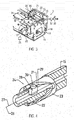
- a paver 1 in Fig. 1 for installation of a covering 6 of bituminous or concrete installation material 5 on a substrate 7 has on a chassis 2 a built-in material bunker 4 and in a cab a control panel P control, for example, with a control system 25 on.
- the control system 25 could be arranged elsewhere in the paver 1 or in a towed by the paver screed 3, in functional association with the controller or the control panel P or arranged on the screed 3 outside control panel P '.
- the screed 3 is attached to Switzerlandholmen 8, which are connected on both sides to articulation points 9 of the paver 1.
- the articulation points 9 can be moved up and down via adjustment devices 10, such as leveling cylinders, for example to adjust the covering thickness S of the installed covering 6.
- the screed 3 comprises, for example, a base screed 11 and extending screeds 12, each with a at least one tamper 14 and a tamper strip comprehensive compression unit 13 and the paving material 5 acting screed plate 18, wherein, preferably, the screed 3 with a small positive angle ⁇ works floating against a parallel to the ground 7 level.
- the Tamperology 14 is cyclically driven in pre-compression in working cycles and performs strokes H with a frequency F. With ongoing installation, the paver 1 moves at a speed of installation V on the ground. 7
- the screed 3 (in the base beam 11 and each Ausziehbohle 12) additionally contains at least one unbalance vibrator (not shown) for applying the Glättbleches 18 with vertical pulses, and, optionally in working direction behind at least one pressure bar of a high compression device (not shown).
- the unbalance vibrator and the high-compression device are optional options of a screed 3, while the tamper 14 may be part of the basic equipment.
- the installation speed V as well as the covering thickness S are installation parameters which may even change or be changed during installation.
- the tamper 14 has to produce a pre-compression in the loose on the substrate 7 poured paving material 5, regardless of changing installation parameters, at least as far as possible should be kept constant. Further installation parameters which may be relevant for the precompression may be the type and consistency of the paving material 5, its temperature, the ambient conditions, the design of the paving screed 3, and the like.
- the pre-compression is kept substantially constant regardless of the installation parameters changing during installation by at least the stroke H of the working cycles of the tamper 14 depending on at least one installation parameter, possibly even automatically adjusted, expediently also the frequency F, namely via the control system 25, which receives or knows at least one installation parameter as a control variable, and on which, preferably, a desired degree of precompression is set as the desired value.
- the control system 25 can be operated with characteristic curves and / or a characteristic map. Each characteristic curve or the characteristic field is predetermined and stored.
- the control system 25 is automatic and computerized.
- Fig. 2 shows a diagram of the stroke H (or the frequency F) on the lining thickness S (or the installation speed V).
- the solid curve H illustrates how the stroke H with increasing lining thickness S (or increasing installation speed V) is continuously increased here.
- dashed lines the measure known from the prior art is indicated to change the stroke H in each case with interrupted installation operation, the obliquely hatched fields X and Y illustrate that the changed after the stair profile stroke H or the pre-compression over a considerable part of the changes in the lining thickness S or the installation speed V does not fit.
- the solid curve F illustrates the also possible change in the frequency with increasing lining thickness S or installation speed V.
- the curves H, F can be stored in a map that works the control system 25 during ongoing installation.
- the characteristic F, H or the map is predetermined so that in view of high and consistent final quality of the built-in coating 6 is always an optimal ratio between the lining thickness and / or the installation speed and at least the stroke H, expediently also the frequency F optimal is.
- the adjustment of the stroke H, and possibly also the frequency F, is expediently either automatically and even during installation under tapping changes of at least one installation parameter such as the lining thickness S and / or the installation speed V, or operator-guided.
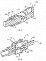
- Fig. 3 illustrates the interior of the screed 3 with the tamper 14.
- the tamper strip 14 is shielded at the front of the screed 3 by a cover 19 (retractable spout) and between the cover 19 and the front edge of the Glättbleches 18 guided substantially vertically movable.
- a bearing block 16 On a lower side of the screed plate 18 supporting frame 17 of the screed 3, a bearing block 16 is mounted, the relative altitude is adjustable for example by means of an adjusting screw 20, such that the tamper strip 14 assumes a certain relative position to the screed plate 18 at the bottom dead center of each work cycle.
- an eccentric shaft 15 rotatably mounted, each having an eccentric portion 22 with a certain eccentricity.
- the eccentric portion 22 is located in a connecting rod 21 which connects the eccentric shaft 15 with the tamper strip 14.
- an eccentric bushing 23 On the eccentric portion 22 of the eccentric shaft 15 is an eccentric bushing 23, for example, in the embodiment shown via an adjusting 24, which is supported on the frame 17, rotatably coupled to the eccentric portion 22 and rotatably mounted in the connecting rod 21.
- the eccentric bushing 23 can rotate relative to the eccentric portion 22 of the eccentric shaft 15 and rotatably coupled in the rotational position respectively set with the eccentric shaft 15.
- the relative rotation of the eccentric bushing 23 relative to the eccentric section 22 effects an adjustment of the stroke, which the connecting rod 21 transmits to the tamper strip 14.
- the adjustment of the stroke can, preferably, be made automatically via the control system 25, which is in operative connection with the adjusting gear 24, in response to changes in certain installation parameters.
- the adjusting mechanism 24 could be actuated or operated as required by the user.
- the representation of the adjusting gear 24 in Fig. 3 is schematically because the adjusting gear 24 of course due to the rotational movement of the eccentric shaft 15 indirectly as Hubverstell Rhein via the eccentric shaft 15 has an effect on the eccentric bushing 23. This will be explained in detail with reference to the further embodiment.
- adjusting the 24 eccentric sleeve 23 is rotatably mounted on the eccentric portion 22 of the eccentric shaft 15.
- This is hollow, for example, such that an internal control rod 27 leads to an outside of the eccentric shaft 15 adjustment 26.
- the control rod 27 is coupled to a in a groove 29 axially adjustable in the eccentric shaft 15, rotatably connected to this driver 28 which engages with an outwardly projecting from the groove 29 extension 30 in a thread-like guide rail 31 of the eccentric bushing 23.
- the eccentric portion 22 has the axis of rotation of the eccentric shaft 15 has a first eccentricity, but is cylindrical on the outer circumference.
- the cylindrical outer circumference of the eccentric bush 23 is eccentric with respect to the cylindrical inner circumference. Since the cylindrical outer periphery of the eccentric bushing 23 is rotatable in the connecting rod 21, and the tamper strip 14 is movable in a fixed vertical plane, the extent of the resulting eccentricity of the first and second eccentricities depends on which relative rotational position between the eccentric bushing 23 and the eccentric portion 22nd is set.
- the effective amount of eccentricity determines half the stroke H of a power stroke.
- the eccentric shaft 15 is, for example, on in Fig. 4 rotatably mounted left end in a bearing block, not shown here and is of in Fig. 4 Right end driven by a hydraulic motor, not shown.
- the adjusting drive 26 can therefore in front of the left-side end in Fig. 4 be arranged in the screed or on the frame 17.
- Fig. 5 differs mainly from Fig. 4 in that the adjusting mechanism 24 contains the driver 28, which is axially displaceable in the outwardly open groove 29 of the eccentric shaft 15, in such a way that the adjusting drive 26 engages via the control rod 27 from the outside of the eccentric shaft 15.
- the extension 30 of the driver 28 engages in the thread-like guide track 31 of the eccentric bushing 22, although relatively rotatably seated on the eccentric portion 22 of the eccentric shaft 15, but rotatably on the driver 28, the groove 29 and the extension 30 in each axial position of the driver 28 remains coupled to the eccentric shaft 15.
- adjusting gear 24 has a rotary indexing mechanism, which is cyclically actuated by the example supported on the frame 17 of the screed adjusting 26 to rotate the eccentric bushing 23 relative to the eccentric portion 22 of the eccentric shaft 15.
- the eccentric bushing 23 is rotatably supported via at least one rolling bearing 32.
- an adjusting mechanism 30 is axially movable but rotatably coupled to the eccentric shaft 15 is arranged.
- a sawtooth toothing 34 (peripheral teeth) is provided, as well as a circumferentially offset sawtooth toothing 35 at the right end of the adjusting 33.
- the eccentric bushing 23 has at both ends corresponding sawtooth teeth 37 and 36.
- the axial length of the eccentric bushing 23 between their sawtooth gears 36, 37 is slightly shorter than the clear width between the sawtooth toothings 35, 34.
- the adjusting mechanism 33 by means of, for example, an annular piston 41 of the adjustment 26 (hydraulically loadable annular chamber 40) hydraulically adjustable axially.
- the left-side end of the adjusting mechanism 33 is supported on a spring 39 of a stop 38 on the eccentric shaft 15.
- Fig. 7 has the adjusting gear 24 as adjusting 26 to the annular piston 41.
- the adjustment drive 26 can be supported on the frame 17 of the screed.
- the annular piston 41 engages directly on an axial end of the eccentric bushing 23, which is pressed by the supported on the stop 38 on the eccentric shaft spring 39 via a stop ring 42 and a rolling bearing 43 axially on a conical portion 22 'of the eccentric portion 22 of the eccentric shaft 15 and rotatably is coupled with the eccentric shaft 15.
- the eccentric bush 23 can be against the force of the spring 39 through the annular piston 41 from the in Fig.
- the eccentric bushing 23 may e.g. with coaxial inner and outer cylindrical peripheries, i. circular cylindrical, formed and rotatably on two opposite guide blocks 44 may be arranged, which are in the outwardly open grooves of the perforated eccentric shaft 15 transversely to the axis of the eccentric shaft 15 slidably and rotatably with the eccentric shaft.
- Each guide block 44 has internally an inclined guide surface 45 which rests on an inclined guide ramp 47 of a control rod 46, which is axially displaceable in the eccentric shaft 15 by means of the adjustment 26 and in the selected setting position.
- the adjusting drive 26 may be formed hydraulically, electrically or mechanically.
- the eccentric bush 23 is cylindrical (manufacturing technology favorable), it acts eccentrically relative to the eccentric portion 22.
- Fig. 9 which is functionally the embodiment of Fig. 8
- the guide blocks 44 are axially displaceable and rotationally fixed to the eccentric shaft 15 coupled.
- a control rod 46 ' which is coupled to the adjusting drive 26 or coupled.
- the oblique guide surface 47 ' is externally formed on the guide block 44 and engages in an axial groove on the inner surface of the eccentric bushing 23 a.
- the oblique guide ramp 45 ' is shaped, so that by axial adjustment of the guide blocks 44, the eccentric bushing similar to in Fig. 8 is moved transversely to the axis of the eccentric shaft and remains rotationally fixed coupled to the eccentric shaft 15.
- the eccentric bushing 23 may be cylindrical.
- the adjusting gear 24 is incorporated into a toggle mechanism, via which the rotational movement of the eccentric shaft 15 is transmitted with its eccentric portion 22 via a rotatably mounted on the eccentric portion 22 thrust rod 48 and a hinge axis 49 on the connecting rod 21 to which the tamper strip 14 is attached.
- the connecting rod 21 preferably, on the same hinge axis 49, one end of an adjusting lever 50 is pivotally coupled, which is supported with a pivot abutment 51 (eg a pin) in a guide track 52 of the bearing block 16 'of the eccentric shaft 15.
- the bearing block 16 ' may be fixed on the frame 17 of the screed.
- the guideway 52 is, for example, a straight or arcuate, slot-shaped slot in the bearing block 16 'and extends in a the eccentric shaft 15 cross-cutting plane.
- the adjusting drive 26 is effective between the bearing block 16 'and the pivot abutment 51 to adjust the pivot abutment 51 within the guide track 52.
- the guideway 52 with respect to the axis of the eccentric shaft 15 and the hinge axis 49 is formed and arranged such that regardless of the adjustment of the pivot abutment 51 in the guideway 52 of the bottom dead center of the strokes of the tamper strip 14 remains stationary in relation to the screed plate 18, ie, only the top dead center shifts during the stroke adjustment.
- the rotation of the eccentric shaft 15 moves via the eccentric portion 22, the push rod 48 substantially parallel to the top of the frame 17 back and forth.
- This oscillating movement causes via the common hinge axis 49 a pivoting movement of the adjusting lever 50 about the pivot abutment 51 following a circular arc section.
- the adjusting lever 50 derives therefrom a substantially vertical lifting component for the connecting rod 21. The extent of this lifting component is changed by adjusting the pivot abutment 51 in the guideway 52.
- the angle of attack ⁇ should be positive but with an optimal size, ie not too shallow and not too steep and is by the Control system 25 kept in optimal size.
- 2 lifting cylinders 28 are hinged to the chassis, which engage the Werholmen 8 and serve to position the screed 3 excavated, for example, for transport, or to perform a screed relief or optionally to increase the contact pressure of the screed 3.
- the tamper 14 of the compression unit 13 is (see Fig. 3 ) For example, by means of an eccentric drive with selectable stroke H and selectable frequency F operable.
- a speed selector 26 is provided for setting the installation speed V.
- the speed selector 26 can be adjusted by an actuator, not shown, if necessary, also from the control system 25 to change the installation speed V.
- the installation speed V is symbolic indicated sensor 31 is detected and transmitted to the control system 25.
- the sensor 31 may be placed in the paver, for example, in the control panel P or in a traction drive or scan a reference on the substrate 7.
- an input section 27 may be provided for inputting parameters and / or displaying parameters.
- the lifting cylinders 28 is at least one actuator 28 ', for example, a solenoid-operated hydraulic valve assigned.
- At least one sensor 30 may be provided, which picks up the temperature, density or consistency of the paving material, for example, immediately before the screed 3 and optionally transmitted as information to the control system 25. This captured information could also be entered by an operator.
- at the screed 3 at least one sensor 29 is provided, which detects the angle of attack ⁇ of the screed relative to the substrate 7. This sensor 29 could tap the angle ⁇ also at the Switzerlandholmen 8. It can be provided over the mounting width several sensors 29.
- a sensor 37 can be provided for picking up the lining thickness S, which scans, for example, the substrate 7 or a reference, not shown, on the substrate 7.
- actuators for adjusting the Tamperhubes H and the tamper frequency F are provided and can be brought by means of the control system 25 generated control signals to implement control signals.
- FIG. 3 shows Fig. 3 the actuator 24 for the Tamperhub H-forming gear 24 for rotating the eccentric bushing 23 relative to the eccentric 22.
- the respective adjusted to the mounting parameters setting the Tamperhubes H automatically via the control system 25.
- the eccentric shaft 15 is rotationally driven, for example by a hydraulic motor 32. Its speed determines the tamper frequency F.
- the actuator 33 for the hydraulic motor 32 may serve a solenoid-operated valve, such as a proportional flow control valve, which can be acted upon by the control system 25 with control signals.
- control system 25 by means of the control system 25 several different machine or construction site or installation material parameters are automatically controlled in dependence of each other, for example, to minimize error rates in the built-in coating 6 and to increase the quality of the built-in coating 6.
- the tamper 14 has to compact the loosely presented paving material 5 so strong that a sufficient for the screed 3 carrying capacity is created. Only then is it guaranteed that the screed 3 with its screed plate 18 with a favorable angle ⁇ is dragged floating.
- the tamper stroke H, the tamper frequency F, the installation speed V and the angle of attack ⁇ depend strongly on each other. If, for example, the installation speed V is reduced, this has an effect on the pre-compression of the paving material while the tamper frequency and leveling cylinder setting remain the same. It increases the carrying capacity of the paving material, so that the screed 3 continues to float and reduces the angle of attack ⁇ .
- At least manipulated variables for the compacting unit 13 or the tamper 14 are automatically controlled and regulated by the control system 25 as a function of the relevant processes or machine parameters. In particular, in this way takes place as a contribution to quality assurance a consistent and optimal compression of the paving material over the entire pave width of the screed.
- the angle of attack ⁇ is detected by means of the sensor 29 or a plurality of transversely distributed sensors 29 and transmitted to the control system 25, or there for specially responsible for these installation parameters controller to adjust the Tamperhub H at a change in the angle of attack ⁇ , so that the angle of attack ⁇ is again reduced to an optimum value or can not change appreciably, so that the target lining thickness S is achieved while the optimal pre-compression remains the same.
- the angle of attack ⁇ can vary over the installation width of the screed 3. Then the control system 25 can make the appropriate adjustment of Tamperhubes H for each tamper 14 individually, so that despite transverse to the installation direction varying covering thickness S, the compression over the pave width remains uniform.
- the tamper stroke H and the tamper frequency F can also be adjusted via the control system 25, and an adjustment of the leveling cylinders 10 may additionally be made as an alternative to an adaptation of the tamper frequency F.
- the adaptation of the tamper frequency F can be made particularly simple by the tamper frequency F automatically corresponding to a change in the tamper stroke H. is adapted to a characteristic curve or in a characteristic field which is input or present in the control system.
- An important installation parameter is, for example, also the density or consistency of the paving material 5. If the road paver 1 is equipped with a sensor 30, as mentioned, by means of which the density or consistency of the paving material can be detected, then the detected value is compared with a target specification, and in the case of a deviation from the target specification via the control system 25, an adaptation of, for example, the tamper stroke H and / or the tamper frequency F and / or the leveling cylinder adjustment is made such that the deviation angle of the detected density or consistency substantially maintains the angle of attack and the same Compression and flatness and thus quality of the coating 6 can be achieved.
- the installation speed V is also a significant installation parameter, since an adaptation requires the tamper stroke H and / or the tamper frequency F and / or the leveling cylinder adjustment, for example via the automatic control system 25.
- Another significant installation parameters are the rigidity of the paving material 5 and / or its temperature. These installation parameters may, for example, be detected individually and combined by means of the sensor 30 or a stiffness and a temperature sensor and transmitted to the control system 25, or entered after detection by an operator at the section 27, whereupon the control system, if advised by the detected values, the tamper stroke H and / or the tamper frequency F and / or the leveling cylinder adjustment adapts accordingly.
- an adjustment to the lifting cylinders 28 can be made, for example, to relieve the screed 3 during installation more or burden with emphasis in the direction of the ground 7, again in view, the angle of attack ⁇ as uniform as possible keep, and let the screed 3 work with even compaction of the coating 6.
Abstract
Die Erfindung betrifft eine Einbaubohle (3) für Straßenfertiger (1), mit einem in zyklischen Arbeitstakten mit wählbarem Hub (H) und wählbarer Frequenz (F) antreibbaren Verdichtungsaggregat, insbesondere einem Tamper (13) mit einer Tamperleiste (14), zum Vorverdichten eines aus Einbaumaterial (5) eingebauten Belages (6), dadurch gekennzeichnet, dass das Verdichtungsaggregat ein Verstellgetriebe (24) zum fernbetätigten Verstellen des Hubs (H) des Verdichtungsaggregats aufweist, und dass in der Einbaubohle (3) das Verstellgetriebe (24) zum Einstellen einer Lage einer Exzenterbuchse (23) relativ zu einer sie lagernden Exzenterwelle (15) vorgesehen ist.

Description
Die Erfindung betrifft eine Einbaubohle gemäß Oberbegriff des Patentanspruchs 1.The invention relates to a screed according to the preamble of
Beim Einbauen eines Belages aus bituminösem oder Beton-Einbaugut mit einem Straßenfertiger hat die schwimmend geschleppte Einbaubohle das Einbaugut über die gesamte Einbaubreite möglichst gleichmäßig zu verdichten und eine geschlossene, ebene Struktur zu erzeugen. Das Verdichtungsaggregat, z.B. ein sogenannter Tamper oder ein Tamper und ein Unwucht-Vibrator, soll eine möglichst hohe, gleichbleibende und über die Belagstärke durchgehende Vorverdichtung erzeugen, damit unterschiedliche oder variierende Belagstärken keinen nennenswerten Einfluss auf die Endverdichtung haben. Der Hub und die Frequenz des Tampers beeinflussen hierbei die Vorverdichtung und das Schwimmverhalten der Einbaubohle. Je größer der Hub ist, desto höher wird die Vorverdichtung und desto tiefer wird vorverdichtet. Die Frequenz lässt sich individuell stufenlos verstellen.
Aus der Informationsschrift "Für jede Aufgabe die richtige Einbaubohle", der Firma Joseph Vögele AG, 68146 Mannheim/DE, Nr. 2400/10/2.1997, Seite 4, ist es bekannt, den Hub des einen Tamper aufweisenden Verdichtungsaggregats manuell dadurch zu verstellen, dass eine in einem die Stampferleiste antreibenden Pleuel drehbare Exzenterbuchse relativ zu einem Exzenterabschnitt der antreibenden Exzenterwelle verdreht wird. Die Exzenterbuchse ist auf den Exzenterabschnitt der Exzenterwelle gespannt und so mit dem Exzenterabschnitt drehfest gekoppelt, und lässt sich nach Lösen einer Spannschraube relativ zum Exzenterabschnitt verdrehen und wieder fixieren. Die Exzenterwelle wird von einem Hydromotor angetrieben, dessen Drehzahl z.B. stufenlos veränderbar ist. Wird vor dem Einbauen eine bestimmte Belagstärke festgelegt, dann wird der Hub auf diese Belagstärke eingestellt. Wird die Belagstärke verändert, müssen der Einbau unterbrochen und der Hub auf die neue Belagstärke eingestellt werden. Da die Belagstärke auch bei laufendem Einbau aufgrund äußerer Einflüsse variieren kann, passt der eingestellte Hub häufig nicht zur Belagstärke, wodurch die Vorverdichtung variiert und sich der Anstellwinkel der Einbaubohle verändern kann, und in der Folge die Ebenheit und Oberflächengüte des Belages leiden. Die Einstellung ist zeitaufwändig und mühsam, da z.B. allein in der Grundbohle acht Pleuel vorgesehen sein können, und erfordert hohe Sorgfalt, um über die Arbeitsbreite gleichförmig vorzuverdichten.From the information document "For each task the right screed", the company Joseph Vögele AG, 68146 Mannheim / DE, no. 2400/10 / 2.1997, page 4, it is known to manually adjust the stroke of a tamping unit having a tamper, a rotatable eccentric bushing rotating in a connecting rod driving the tamper strip is rotated relative to an eccentric section of the driving eccentric shaft. The eccentric bushing is stretched on the eccentric portion of the eccentric shaft and thus rotatably coupled to the eccentric, and can rotate after loosening a clamping screw relative to the eccentric and fix it again. The eccentric shaft is driven by a hydraulic motor whose speed is e.g. is infinitely variable. If a certain lining thickness is determined before installation, then the stroke is set to this lining thickness. If the covering thickness is changed, the installation must be interrupted and the stroke adjusted to the new covering thickness. Since the lining thickness can vary even during installation due to external influences, the set stroke often does not match the lining thickness, whereby the precompression varies and the angle of attack of the screed may change, and as a result the flatness and surface quality of the lining suffer. The adjustment is time consuming and cumbersome since e.g. eight connecting rods may be provided in the base beam alone, and requires great care to uniformly pre-compact over the working width.
Aus
Aus
Der Erfindung liegt die Aufgabe zugrunde, eine Einbaubohle und einen Straßenfertiger anzugeben, die eine gleichmäßig hohe Qualität eines eingebauten Belages ermöglichen, so z.B. den Einbau eines Belages mit in Arbeitsfahrtrichtung gleichmäßiger Stärke und sowohl in der als auch quer zur Arbeitsfahrtrichtung gleichförmiger Verdichtung.The invention has for its object to provide a screed and a paver that allow a consistently high quality of a built-in coating, so For example, the installation of a covering with uniform working strength in the direction of travel and both in the transverse direction and the working direction uniform compression.
Die gestellte Aufgabe wird mit den Merkmalen des Patentanspruchs 1 gelöst.The stated object is achieved with the features of
Da zumindest der Hub des Verdichtungsaggregats abhängig von wenigstens einem Einbauparameter wie zumindest der Einbaugeschwindigkeit und/oder Belagstärke automatisch verstellt wird, stehen der Hub und der jeweilige Einbauparameter in einem optimalen Verhältnis zueinander, aus dem nicht nur eine weitgehend konstante Vorverdichtung unabhängig von Variationen der Einbauparameter resultiert, sondern ein optimal kleiner positiver Anstellwinkel der Einbaubohle gehalten wird, der eine geschlossene und ebene Oberfläche des Belages und gleichbleibend hohe Qualität des eingebauten Belages gewährleistet. Die Verstellungen können bequem an allen Pleueln gleichzeitig vorgenommen werden.Since at least the stroke of the compression unit is automatically adjusted depending on at least one installation parameter such as at least the installation speed and / or covering thickness, the stroke and the respective installation parameters are in an optimal relationship to each other, resulting in not only a largely constant pre-compression regardless of variations of the installation parameters but an optimally small positive angle of attack of the screed is maintained, which ensures a closed and even surface of the lining and consistently high quality of the installed lining. The adjustments can be made conveniently on all connecting rods at the same time.
In der Einbaubohle ermöglicht es das, vorzugsweise sogar bei laufendem Einbau betätigbare, Verstellgetriebe, den Hub des Verdichtungsaggregates so zu verstellen, dass der Hub beispielsweise vor oder bei Änderungen der Einbaugeschwindigkeit und/oder der Belagstärke, wie sie beim Einbauen entweder aufgrund äußerer Einflüsse auftreten oder mit Absicht vorgenommen werden, jeweils weitgehend optimal zur Einbaugeschwindigkeit und/oder Belagstärke passt, woraus eine optimale und konstante Vorverdichtung und hohe Qualität des eingebauten Belages resultieren. Wenn sich der Hub bei laufendem Einbau verstellen lässt, zweckmäßig bei allen Pleueln, braucht der Einbaubetrieb zur Hubverstellung nicht unterbrochen zu werden, und wird das Personal entlastet. Der Fertigerführer oder ein Bedienungsmann an der Einbaubohle kann die Verstellung alternativ nach Bedarf vornehmen. Besonders zweckmäßig erfolgt die Verstellung jedoch automatisch in Abhängigkeit von Einbauparametern wie der Einbaugeschwindigkeit und/oder Belagstärke, so dass die gleichmäßige hohe Endqualität des Belages ohne nennenswerte Einflussnahme des Personals erreicht wird.In the screed allows, preferably even during ongoing installation operable adjusting, to adjust the stroke of the compression unit so that the hub, for example, before or during changes in installation speed and / or the thickness of lining, as they occur during installation either due to external influences or to be made on purpose, in each case largely optimally fits the speed of installation and / or covering thickness, resulting in an optimal and constant pre-compression and high quality of the installed lining. If the stroke can be adjusted during installation, which is advisable for all connecting rods, the stroke adjustment installation does not need to be interrupted, and the personnel is relieved. The paver operator or an operator on the screed may alternatively make the adjustment as needed. However, the adjustment is particularly useful automatically depending on installation parameters such as the installation speed and / or covering thickness, so that the uniform high final quality of the coating is achieved without appreciable influence of the staff.
Der zum Durchführen des Verfahrens und mit dieser Einbaubohle ausgestattet Straßenfertiger ermöglicht es, dank des Regelsystems und von diesem generierter und von Stellgliedern umgesetzter Stellgrößen, eine gleichmäßig hohe Qualität eines eingebauten Belages zu erzielen, wobei in einem automatischen Ablauf eine in Einbaufahrtrichtung gleichmäßige Belagstärke und eine sowohl in Einbaufahrtrichtung als auch quer dazu gleichförmige Verdichtung geregelt werden, ohne dass dabei ein Bediener komplizierte Aufgaben zu lösen oder Parameter zu wählen braucht. Denn die Stellgrößen, die zumindest durch Stellglieder zur Erstellung des Hubs und/oder der Frequenz des Tampers umgesetzt werden, werden in Abhängigkeit von relevanten Prozessparametern oder Maschinenparametern bzw. Einbauparametern automatisch und prozessorientiert generiert.The road paver equipped to carry out the method and with this screed makes it possible, thanks to the control system and generated by actuators actuators, to achieve a consistently high quality of a built-in covering, in an automatic sequence a uniform in installation direction lining thickness and both be regulated in the installation direction as well as transversely to uniform compression, without requiring an operator to solve complicated tasks or to select parameters. Because the manipulated variables, at least by actuators for Creation of the stroke and / or the frequency of the tampers are generated automatically and process-oriented depending on relevant process parameters or machine parameters or installation parameters.
Hierbei umfasst das Verdichtungsaggregat zumindest einen Tamper mit jeweils mehreren Pleueln in jedem Abschnitt der Einbaubohle, d.h. in der Grundbohle, in jeder Ausziehbohle, und gegebenenfalls auch in an den Ausziehbohlen angebauten Bohlenverbreiterungsteilen. Um eine noch bessere Vorverdichtung zu erzielen, kann der jeweilige Tamper mit einem Unwucht-Vibrator kombiniert werden, der das Glättblech der Einbaubohle mit im Wesentlichen vertikal wirkenden Unwuchtimpulsen beaufschlagt. Die Vibrationsfrequenz kann, beispielsweise, wie bekannt, über ein Stromregelventil in einem bestimmten Bereich verstellbar sein, und verfahrensgemäß ebenfalls in Abhängigkeit von dem zumindest einen Einbauparameter automatisch mitverstellt werden. Sollte die Einbaubohle auch über eine Hochverdichtungseinrichtung verfügen (siehe die obenerwähnte technische Information "Für jede Aufgabe die richtige Einbaubohle", Seite 8), die mit hochfrequenten hydraulischen Druckimpulsen arbeitet, deren Frequenz und Pressdruck einstellbar sind, kann zweckmäßig auch die Verstellung der Hochverdichtungseinrichtung abhängig von solchen Einbauparametern vorgenommen, so dass beispielsweise bei variierender Einbaugeschwindigkeit und/oder extrem ungleichmäßiger Belagstärke dennoch eine konstant hohe Endqualität des eingebauten Belages resultiert.Here, the compacting unit comprises at least one tamper with a plurality of connecting rods in each section of the screed, i. in the basic screed, in each extending screed, and possibly also in screed widening parts attached to the screed. In order to achieve even better pre-compaction, the respective tamper can be combined with an unbalance vibrator, which acts on the screed plate of the screed with substantially vertically acting unbalance pulses. The vibration frequency can, for example, as known, be adjustable over a flow control valve in a certain range, and according to the method also be automatically mitverstellt depending on the at least one installation parameters. If the screed also has a high compression device (see the above-mentioned technical information "The right screed for each task", page 8), which works with high-frequency hydraulic pressure pulses, the frequency and pressure are adjustable, can also be appropriate adjustment of the high compression device depending on made such installation parameters, so that, for example, with varying installation speed and / or extremely uneven lining thickness results in a consistently high final quality of the installed coating.
Speziell im Hinblick darauf, im eingebauten Belag keine spürbaren Änderungen der Belagstärke zu erzeugen bzw. die Oberfläche eben zu formen, ist es bei einer zweckmäßigen Verfahrensvariante günstig, flankierend zum Hub auch die Frequenz und/oder sogar den Anstellwinkel der Einbaubohle abhängig von wenigstens einem erfassten oder eingegebenen Einbauparameter automatisch zu verstellen. Der Anstellwinkel wird mittels der Nivellierzylinder am Fertiger verstellt, während die Frequenz des Tampers, falls erforderlich, beispielsweise über die Drehzahl des Drehantriebs des Tampers verstellt wird.Especially in view of producing no noticeable changes in the covering thickness or forming the surface in the installed covering, it is favorable in a suitable method variant flanking the stroke and the frequency and / or even the angle of attack of the screed depending on at least one detected or automatically adjust the entered installation parameters. The angle of attack is adjusted by means of the leveling cylinder on the paver, while the frequency of the tamper, if necessary, for example, is adjusted via the rotational speed of the rotary drive of the tamper.
Um einen Bediener weitgehend zu entlasten, wird zweckmäßig verfahrensgemäß als der für die Verstellung zumindest des Hubs des Tampers ursächliche Einbauparameter entweder der Anstellwinkel der Einbaubohle und/oder die Dichte und/oder die Steifigkeit und/oder die Temperatur des Einbaumaterials erfasst, vorzugsweise mittels wenigstens eines Sensors, und, vorzugsweise, mit einer Sollvorgabe verglichen, ehe die Verstellung zumindest des Hubs erfolgt. Der Anstellwinkel ist z.B. ein außerordentlich aussagefähiger Indikator für eine optimale Verdichtung, die wesentlich vom Hub des Tampers abhängt.In order to relieve an operator to a great extent, it is expedient according to the method to record the setting angle of the screed and / or the density and / or the rigidity and / or the temperature of the paving material, preferably by means of at least one, as the adjustment parameter for the adjustment of at least the stroke of the tamper Sensors, and, preferably, compared with a target specification, before the adjustment of at least the stroke takes place. The angle of attack is, for example, an extraordinarily meaningful indicator of optimum compaction, which depends essentially on the stroke of the tamper.
Bei einer zweckmäßigen Verfahrensvariante wird flankierend neben dem Hub auch die Frequenz des Verdichtungsaggregates automatisch, vorzugsweise, entlang einer von wenigstens einem Einbauparameter abhängigen Kennlinie oder in einem Kennfeld verstellt. Die automatische Frequenzeinstellung kann auch einen Unwucht-Vibrator miteinschließen. Dadurch wird sichergestellt, dass sowohl der Hub als auch die Frequenz jeweils in einem optimalen Verhältnis zum Einbauparameter sind.In an expedient variant of the method, in addition to the stroke, the frequency of the compression unit is automatically, preferably, adjusted along a characteristic curve dependent on at least one installation parameter or in a characteristic field. The automatic frequency adjustment may also include an unbalance vibrator. This ensures that both the stroke and the frequency are in optimum proportion to the installation parameter.
Bei einer zweckmäßigen Verfahrensvariante wird die Frequenz des Tampers entsprechend einer Kennlinie oder eines Kennfeldes verstellt, beispielsweise in direkter Abhängigkeit von dem jeweils eingestellten Hub. Die Kennlinie oder das Kennfeld können jedoch auch auf einer vorbestimmten Proportionalität zwischen dem Hub und der Frequenz beruhen, wobei, vorzugsweise, diese Proportionalität abhängig von wenigstens einem Einbauparameter oder einer vorbestimmten Änderung wenigstens eines Einbauparameters gewählt wird, wie beispielsweise der Einbaugeschwindigkeit, des Anstellwinkels der Einbaubohle, der Dichte oder Temperatur oder Steifigkeit des Einbaumaterials, und dgl..In an expedient variant of the method, the frequency of the tamper is adjusted according to a characteristic curve or a characteristic field, for example in direct dependence on the respectively set stroke. However, the characteristic curve or characteristic map can also be based on a predetermined proportionality between the stroke and the frequency, wherein, preferably, this proportionality is selected as a function of at least one installation parameter or a predetermined change of at least one installation parameter, such as the installation speed, the angle of attack of the screed , the density or temperature or rigidity of the paving material, and the like.
Bei einer zweckmäßigen Verfahrensvariante, bei der das Verdichtungsaggregat einen Tamper mit einer über wenigstens ein Pleuel, eine Exzenterbuchse und eine angetriebene Exzenterwelle zu im Wesentlichen vertikalen Arbeitstakten antreibbaren Tamperleiste aufweist, werden, z.B. sogar bei laufendem Einbau, die Exzenterbuchse und die Exzenterwelle relativ zueinander verdreht und der aus der relativen Drehlage zwischen Exzenterbuchse und Exzenterwelle resultierende Hub der Tamperleiste entlang der Kennlinie oder im Kennfeld verstellt. Die Kennlinie bzw. das Kennfeld wird vorab festgelegt. Die Kennlinie bzw. das Kennfeld kann so gewählt sein, dass die Vorverdichtung im Belag unabhängig von Änderungen der Belagstärke und/oder der Einbaugeschwindigkeit zumindest im Wesentlichen konstant bleibt.In an expedient variant of the method, in which the compacting unit has a tamper with a tamper strip which can be driven via at least one connecting rod, an eccentric bushing and a driven eccentric shaft to substantially vertical working strokes, e.g. even with ongoing installation, the eccentric bushing and the eccentric shaft rotated relative to each other and adjusted from the relative rotational position between the eccentric bushing and eccentric shaft stroke of the tamper bar along the curve or in the map. The characteristic curve or the characteristic field is determined in advance. The characteristic curve or the characteristic diagram can be selected such that the precompression in the lining remains at least substantially constant, independently of changes in the lining thickness and / or the installation speed.
Verfahrensgemäß kann ferner zumindest der Hub durch ein Regelsystem verstellt werden, für das ein bestimmter Vorverdichtungsgrad eingestellt wird und dem als Regelführungsgrößen Einbauparameter wie zumindest die Einbaugeschwindigkeit und/oder die Belagstärke eingegeben bzw. zugeführt wird oder werden. Der Maschinenführer bzw. ein Bedienungsmann an der Einbaubohle brauchen sich bei laufendem Einbau nicht um die Verstellung zu kümmern, obwohl, bei einer einfachen Verfahrensvariante, die Verstellung individuell von Hand vorgenommen werden kann. Dazu braucht der Bediener nicht am Verdichtungsaggregat zu manipulieren, sondern stellt er die jeweilige Stellgröße, z.B. für den Hub, bequem am Regelsystem oder im Bedienpult ein, die dann von einem Stellglied entsprechend umgesetzt wird.According to the method, furthermore, at least the stroke can be adjusted by a control system for which a certain degree of precompression is set and the control parameters such as at least the installation speed and / or the lining thickness are input or supplied. The machine operator or an operator on the screed need not worry about the adjustment during installation, although, in a simple process variant, the adjustment can be made individually by hand. For this purpose, the operator does not need to manipulate the compression unit, but he provides the respective manipulated variable, eg for the hub, conveniently on Control system or in the control panel, which is then implemented by an actuator accordingly.
Zweckmäßig wird dabei der Hub der Tamperleiste durch ein zwischen der Exzenterwelle und der Exzenterbuchse angeordnetes Verstellgetriebe hydraulisch und/oder elektrisch und/oder mechanisch verstellt, zweckmäßig entweder kontinuierlich oder in vorgegebenen, zuvor als optimal ermittelten Schritten.Appropriately, the stroke of the tamper bar is adjusted hydraulically and / or electrically and / or mechanically by means of an adjusting mechanism arranged between the eccentric shaft and the eccentric bush, expediently either continuously or in predetermined, previously determined as optimal steps.
In der Einbaubohle ist zweckmäßig ein hydraulisch und/oder elektrisch und/oder mechanisch betätigbares Verstellgetriebe vorgesehen, das, gegebenenfalls selbst bei laufendem Einbau, die jederzeitige Verstellung des Hubes ermöglicht, ohne manuell eingreifen zu müssen.In the screed advantageously a hydraulically and / or electrically and / or mechanically actuated adjusting mechanism is provided, which allows, if necessary, even during ongoing installation, the adjustment of the stroke at any time, without having to intervene manually.
Hierfür kann, entweder an der Einbaubohle oder im Straßenfertiger, ein mit dem Verstellgetriebe operativ verbundenes, automatisches, vorzugsweise computerisiertes, Regelsystem vorgesehen sein, in das Einbauparameter wie zumindest die Einbaugeschwindigkeit und/oder die Belagstärke eingegeben werden oder die dort vorhanden sind, und an dem beispielsweise ein durch das Verdichtungsaggregat zu erzeugender Vorverdichtungsgrad einstellbar ist. Das Regelsystem passt dann bei laufendem Einbau den Hub automatisch an sich abzeichnende Änderungen zumindest eines Einbauparameters an.For this purpose, either on the screed or in the paver, an operatively connected to the adjusting, automatic, preferably computerized, control system be provided in the installation parameters such as at least the installation speed and / or the lining thickness are entered or there are, and on the For example, a degree of compaction to be generated by the compacting unit is adjustable. The control system then automatically adapts the stroke to changes in at least one installation parameter that are apparent during ongoing installation.
Hierfür sollte das Regelsystem wenigstens eine von Einbauparametern abhängige Kennlinie oder ein Kennfeld zur automatischen Verstellung des Hubes oder des Hubes und der Frequenz der Arbeitstakte des Verdichtungsaggregates aufweisen.For this purpose, the control system should have at least one of installation parameters dependent characteristic or a map for the automatic adjustment of the stroke or the stroke and the frequency of the working cycles of the compression unit.
Bei einer zweckmäßigen Ausführungsform der Einbaubohle ist das Verstellgetriebe zwischen einer drehantreibbaren Exzenterwelle in der Einbaubohle und einer auf der Exzenterwelle in einem die Tamperleiste mit im Wesentlichen vertikalen Arbeitstakten antreibenden Pleuel drehbaren Exzenterbuchse vorgesehen. Der Hub der Tamperleiste ist somit durch eine relative Drehverstellung zwischen der Exzenterbuchse und der Exzenterwelle verstellbar. Abhängig von der relativen Drehposition der Exzenterbuchse auf der Exzenterwelle resultiert der halbe Hub eines Arbeitstaktes aus der Summe der Exzentrizität eines Exzenterabschnittes der Exzenterwelle und einem Teilbereich bis zum Maximum der Exzentrizität der Exzenterbuchse.In an expedient embodiment of the screed, the adjusting mechanism is provided between a rotatably driven eccentric shaft in the screed and an eccentric bush rotatable on the eccentric shaft in a connecting rod which drives the tamper strip with essentially vertical working strokes. The stroke of the Tamperleiste is thus adjustable by a relative rotational adjustment between the eccentric bushing and the eccentric shaft. Depending on the relative rotational position of the eccentric bushing on the eccentric shaft, half the stroke of a power stroke results from the sum of the eccentricity of an eccentric portion of the eccentric shaft and a portion up to the maximum of the eccentricity of the eccentric bushing.
Bei einer anderen zweckmäßigen Ausführungsform der Einbaubohle ist das Verstellgetriebe zwischen einer drehantreibbaren Exzenterwelle in der Einbaubohle und einer drehfest auf der Exzenterwelle angeordneten, jedoch quer zur Achse der Exzenterwelle verschiebbaren, in einem die Tamperleiste antreibenden Pleuel drehbar gelagerten Exzenterbuchse derart angeordnet, dass der Hub durch eine Querverschiebung der Exzenterbuchse relativ zur Exzenterwelle verstellbar ist. Das dann wirksame Ausmaß der Exzentrizität der Exzenterbuchse richtet sich nach dem Ausmaß der Querverschiebung der Exzenterbuchse relativ zur Exzenterwelle. Die Exzenterbuchse wirkt exzentrisch, kann aber kreiszylindrisch ausgebildet sein.In another expedient embodiment of the screed, the adjusting mechanism is arranged between a rotatably driven eccentric shaft in the screed and a rotationally fixed on the eccentric shaft, but displaceable transversely to the axis of the eccentric shaft, rotatably mounted in a tamper strip driving connecting rod eccentric bushing arranged such that the stroke is adjustable by a transverse displacement of the eccentric bushing relative to the eccentric shaft. The then effective extent of the eccentricity of the eccentric bush depends on the extent of the transverse displacement of the eccentric bushing relative to the eccentric shaft. The eccentric bushing acts eccentrically, but can be formed circular cylindrical.
Bei einer weiteren zweckmäßigen Ausführungsform der Einbaubohle ist das Verstellgetriebe zwischen einem eine drehantreibbare Exzenterwelle stützenden Lagerbock und einem mit einem die Tamperleiste antreibenden Pleuel gelenkig verbundenen, im Lagerbock verstellbaren Verstellhebel angeordnet (Kniehebelprinzip), wobei der Verstellhebel und eine von der Exzenterwelle antreibbare Schubstange in einer gemeinsamen Gelenkachse mit dem Pleuel gekoppelt sind, derart, dass eine Verstellung des Verstellhebels im Lagerbock den über die Schubstange von der Rotation der Exzenterwelle erzeugten, wirksamen Hub der Tamperleiste verändert.In a further advantageous embodiment of the screed, the adjusting between a rotatably driven eccentric shaft bearing bracket and a pivotally connected to the tamper bar connecting rod, adjustable in the bearing lever is arranged (toggle principle), wherein the adjusting lever and a driven by the eccentric shaft push rod in a common Joint axis are coupled to the connecting rod, such that an adjustment of the adjusting lever in the bearing block changed over the push rod generated by the rotation of the eccentric shaft, effective stroke of the tamper bar.
Bei der Ausführungsform mit der relativ zur Exzenterwelle verdrehbaren Exzenterbuchse ist zweckmäßig in der Exzenterwelle ein axial verstellbarer Mitnehmer drehfest gelagert, der in eine gewindegangartige Führungsbahn der auf der Exzenterwelle verdrehbaren Exzenterbuchse eingreift. Bei einer Verstellung, vorzugsweise auf elektrischem und/oder hydraulischem und/oder mechanischem Weg, des Mitnehmers in Achsrichtung der Exzenterwelle wird über die gewindegangartige Führungsbahn die Exzenterbuchse verdreht und in der jeweils gewählten Einstellung wieder drehfest fixiert.In the embodiment with the eccentric shaft rotatable relative to the eccentric shaft expediently rotatably mounted in the eccentric shaft an axially adjustable driver, which engages in a thread-like guide track of the eccentric shaft rotatable eccentric bushing. During an adjustment, preferably by electrical and / or hydraulic and / or mechanical means, of the driver in the axial direction of the eccentric shaft, the eccentric bushing is rotated via the thread-like guide track and fixed again in a rotationally fixed manner in the respectively selected setting.
Bei einer alternativen Ausführungsform ist in der Exzenterwelle drehfest ein axial beweglicher Verstellmechanismus angeordnet, der taktweise ein mit der drehbar gelagerten Exzenterbuchse zusammenwirkendes Dreh-Schrittschaltwerk betätigt, um die Exzenterbuchse in Schritten relativ zur Exzenterwelle zu verdrehen, und in der gewählten Drehposition drehfest mit der Exzenterwelle zu kuppeln.In an alternative embodiment, an axially movable adjusting mechanism is arranged rotatably in the eccentric, the clockwise cooperating with the rotatably mounted eccentric rotary stepper to rotate the eccentric bush in steps relative to the eccentric shaft, and rotatably in the selected rotational position with the eccentric shaft couple.
Bei einer weiteren alternativen Ausführungsform kann zwischen der Exzenterwelle und der Exzenterbuchse ein Spannmechanismus vorgesehen sein, der die Exzenterbuchse kraftschlüssig oder reibschlüssig oder formschlüssig mit der Exzenterwelle kuppelt und durch einen in der Einbaubohle abgestützten Axial-Lösemechanismus vorübergehend in eine Lösestellung bringbar ist, in der die Kopplung zwischen der Exzenterwelle und der Exzenterbuchse aufgehoben wird und diese beiden Komponenten relativ zueinander verdrehbar sind oder selbsttätig verdreht werden.In a further alternative embodiment may be provided between the eccentric shaft and the eccentric bush, a clamping mechanism which couples the eccentric positively or frictionally or positively with the eccentric shaft and temporarily supported by a supported in the screed axial release mechanism in a release position, in which the coupling is canceled between the eccentric shaft and the eccentric bush and these two components are rotatable relative to each other or are automatically rotated.
Bei einer weiteren, zweckmäßigen Ausführungsform mit der quer zur Achse der Exzenterwelle verlagerbaren Exzenterbuchse ist zwischen der Exzenterwelle und der drehfest mit der Exzenterwelle gekuppelten Exzenterbuchse mindestens ein mittels wenigstens einer in der Exzenterwelle axial verlagerbare Steuerstange quer zur Exzenterwelle verstellbarer, die Exzenterbuchse tragender Führungsstein mit einer schrägen Führungsfläche vorgesehen. Über die schräge Führungsfläche wird der Führungsstein quer zur Achse der Exzenterwelle verlagert, um die Exzenterbuchse zu verstellen bzw. um deren wirksamen Anteil der Exzentrizität zu ändern. Die Exzenterbuchse braucht hier nicht exzentrisch ausgebildet zu sein, sondern kann zylindrisch sein.In a further expedient embodiment with the eccentric bush displaceable transversely to the axis of the eccentric shaft, between the eccentric shaft and the eccentric bush rotatably coupled to the eccentric shaft, at least one control shaft adjustable by means of at least one control rod axially displaceable in the eccentric shaft is adjustable with respect to the eccentric shaft, guiding the eccentric bushing with an oblique guide Guidance surface provided. About the inclined guide surface of the guide stone is displaced transversely to the axis of the eccentric shaft to adjust the eccentric bush or to change their effective portion of the eccentricity. The eccentric bushing does not need to be eccentric here, but may be cylindrical.
Hierbei ist es zweckmäßig, wenn die schräge Führungsfläche des Führungssteins, zweckmäßig zweier diametral gegenüberliegender Führungssteine, axial verschiebbar an einer schrägen Rampe entweder in der Exzenterbuchse oder an der Steuerstange anliegt.It is expedient if the inclined guide surface of the guide block, expediently two diametrically opposite guide blocks, axially displaceable abuts an inclined ramp either in the eccentric bushing or on the control rod.
Bei einer zweckmäßige Ausführungsform, bei der die Tamperleiste über einen Kniehebelmechanismus angetrieben wird, weist der Lagerbock eine gerade oder bogenförmige Führungsbahn auf, in die ein Schwenkwiderlager des Verstellhebels eingreift, das mittels des Verstellgetriebes entlang der Führungsbahn verlagerbar und in gewählten Einstellpositionen fixiert ist, wobei die Verlaufsrichtung der Führungsbahn zumindest in etwa zur Achse der Exzenterwelle weist. Die Verstellung des Schwenkwiderlagers des Verstellhebels resultiert in einer Änderung von der Exzenterwelle abgegriffenen Hubs der Tamperleiste. In diesem Fall ist es zweckmäßig, wenn die Führungsbahn in Bezug auf die Achse der Exzenterwelle und die Gelenkachse am Pleuel derart angeordnet ist, dass ein unterer Totpunkt des von der Exzenterwelle induzierten Arbeitstaktes der mit dem Pleuel verbundenen Tamperleiste unabhängig von der Einstellposition des Schwenkwiderlagers des Verstellhebels entlang der Führungsbahn ortsfest bleibt, vorzugsweise oder beispielsweise ortsfest in Relation zu einem an einem den Lagerbock tragenden Rahmen der Einbaubohle montierten Glättblech. Dies bedeutet, dass nur der obere Totpunkt des Arbeitstaktes in Hochrichtung verstellt wird, und sich die Lage des unteren Totpunktes in Bezug auf das Glättblech beim Verstellen des Hubes nicht verändert.In an expedient embodiment, in which the tamper strip is driven by a toggle mechanism, the bearing block has a straight or arcuate guideway into which a pivot abutment of the adjusting lever engages, which is displaceable by means of the adjusting mechanism along the guideway and fixed in selected Einstellpositionen, wherein the Course of the guideway has at least approximately to the axis of the eccentric shaft. The adjustment of the swiveling abutment of the adjusting lever results in a change of the eccentric shaft tapped strokes of the tamper strip. In this case, it is expedient for the guideway to be arranged with respect to the axis of the eccentric shaft and the articulation axis on the connecting rod in such a way that a bottom dead center of the work cycle induced by the eccentric shaft of the tamper bar connected to the connecting rod is independent of the setting position of the swiveling abutment of the adjusting lever remains stationary along the guideway, preferably or for example stationary in relation to a glazed plate mounted on a frame supporting the bearing block screed. This means that only the top dead center of the power stroke is adjusted in the vertical direction, and the position of the bottom dead center with respect to the screed plate does not change when adjusting the stroke.
Um Einbauparameter oder Änderungen von Einbauparametern erfassen und dem Regelsystem übermitteln oder in dieses eingeben zu können, ist bei einer zweckmäßigen Ausführungsform des Straßenfertigers am Straßenfertiger selbst und/oder der Einbaubohle und/oder den Holmen wenigstens ein Sensor, vorzugsweise mehrere in der und quer zur Einbaufahrtrichtung verteilte Sensoren, zum Erfassen von Ist-Einbauparametern vorgesehen, wobei die Sensoren mit dem Regelsystem verknüpft sind oder verknüpfbar sind. Da zumindest relevante Einbauparameter, wie zumindest der Anstellwinkel der Einbaubohle, oder Änderungen davon über die Sensoren erfassbar und an das Regelsystem übermittelbar sind, ist der Bediener entlastet, und ergibt sich eine gleichbleibend hohe Qualität des eingebauten Belages.To capture installation parameters or changes of installation parameters and to submit the control system or enter into this, is in an expedient embodiment of the paver on the paver itself and / or the screed and / or the spars at least one sensor, preferably several in and across the installation direction distributed sensors, designed to record actual installation parameters, wherein the sensors are linked to the control system or can be linked. Since at least relevant installation parameters, such as at least the angle of attack of the screed, or changes thereof can be detected by the sensors and transmitted to the control system, the operator is relieved, and results in a consistently high quality of the installed coating.
Bei einer weiteren zweckmäßigen Ausführungsform ist am Straßenfertiger und/oder der Einbaubohle eine Eingabe- und Anzeigesektion am Regelsystem oder einer mit dem Regelsystem verknüpften Maschinensteuerung zum zusätzlichen oder alternativen Einstellen von Größen, Werten oder Parametern, zumindest für den Hub und/oder die Frequenz, aber auch den Anstellwinkel der Einbaubohle, vorgesehen, die durch Bediener benutzbar ist, um in das Regelsystem bedarfsabhängig zusätzliche Informationen einzugeben.In a further expedient embodiment, the paver and / or screed has an input and display section on the control system or a machine control associated with the control system for additional or alternative setting of quantities, values or parameters, at least for the lift and / or frequency, however also the angle of the screed, provided that can be used by the operator to enter additional information in the control system as needed.
Anhand der Zeichnungen werden Ausführungsformen des Erfindungsgegenstandes erläutert. Es zeigen:
- Fig. 1
- eine schematische Seitenansicht eines mit einer Einbaubohle ausgestatteten Straßenfertigers beim Einbauen eines Belages,
- Fig. 2
- ein Diagramm zur Verdeutlichung zweier Kennlinien bzw. eines Kennfeldes,
- Fig. 3
- eine Perspektivansicht eines Teiles einer mit einem Verdichtungsaggregat ausgestatteten Einbaubohle,
- Fig. 4
- eine Perspektivschnittdarstellung einer Ausführungsform einer Hubverstelleinrichtung,
- Fig. 5
- eine perspektivische Teilschnittansicht einer weiteren Ausführungsform einer Hubverstelleinrichtung,
- Fig. 6
- einen Längsschnitt einer weiteren Ausführungsform einer Hubverstelleinrichtung,
- Fig. 7
- einen Längsschnitt einer weiteren Ausführungsform einer Hubverstelleinrichtung,
- Fig. 8
- eine Perspektivschnittansicht einer weiteren Ausführungsform einer Hubverstelleinrichtung,
- Fig. 9
- eine Perspektivschnittdarstellung einer weiteren Ausführungsform einer Hubverstelleinrichtung, und
- Fig. 10
- eine Perspektivansicht einer weiteren Ausführungsform einer Hubverstelleinrichtung.
- Fig. 1
- a schematic side view of a equipped with a screed paver when installing a coating,
- Fig. 2
- a diagram to illustrate two characteristics or a characteristic field,
- Fig. 3
- a perspective view of a part of a screed equipped with a compactor,
- Fig. 4
- a perspective sectional view of an embodiment of a Hubverstelleinrichtung,
- Fig. 5
- a perspective partial sectional view of another embodiment of a Hubverstelleinrichtung,
- Fig. 6
- a longitudinal section of another embodiment of a Hubverstelleinrichtung,
- Fig. 7
- a longitudinal section of another embodiment of a Hubverstelleinrichtung,
- Fig. 8
- a perspective sectional view of another embodiment of a Hubverstelleinrichtung,
- Fig. 9
- a perspective sectional view of another embodiment of a Hubverstelleinrichtung, and
- Fig. 10
- a perspective view of another embodiment of a Hubverstelleinrichtung.
Ein Straßenfertiger 1 in
Die Einbaubohle 3 ist an Zugholmen 8 befestigt, die beidseitig an Anlenkstellen 9 des Straßenfertigers 1 angeschlossen sind. Die Anlenkstellen 9 können über Verstelleinrichtungen 10, wie Nivellierzylinder, auf- und abverstellt werden, beispielsweise um die Belagstärke S des eingebauten Belages 6 einzustellen. Die Einbaubohle 3 umfasst beispielsweise eine Grundbohle 11 und daran verfahrbare Ausziehbohlen 12, jeweils mit einem zumindest einen Tamper 14 bzw. eine Tamperleiste umfassenden Verdichtungsaggregat 13 und einem das Einbaumaterial 5 beaufschlagenden Glättblech 18, wobei, vorzugsweise, die Einbaubohle 3 mit einem kleinen positiven Anstellwinkel α gegenüber einer zum Untergrund 7 parallelen Ebene schwimmend arbeitet. Die Tamperleiste 14 ist zur Vorverdichtung zyklisch in Arbeitstakten antreibbar und führt Hübe H mit einer Frequenz F aus. Bei laufendem Einbau fährt der Straßenfertiger 1 mit einer Einbaugeschwindigkeit V auf dem Untergrund 7.The
Gegebenenfalls enthält die Einbaubohle 3 (in der Grundbohle 11 und jeder Ausziehbohle 12) zusätzlich wenigstens einen Unwucht-Vibrator (nicht gezeigt) zum Beaufschlagen des Glättbleches 18 mit vertikalen Impulsen, und, gegebenenfalls in Arbeitsfahrtrichtung hinten zumindest eine Pressleiste einer Hochverdichtungseinrichtung (nicht gezeigt). Der Unwucht-Vibrator und die Hochverdichtungseinrichtung sind wahlweise Optionen einer Einbaubohle 3, während der Tamper 14 zur Grundausstattung gehören kann.Optionally, the screed 3 (in the
Die Einbaugeschwindigkeit V wie auch die Belagstärke S sind Einbauparameter, die sich gegebenenfalls sogar bei laufendem Einbau ändern oder geändert werden können. Der Tamper 14 hat eine Vorverdichtung im locker auf den Untergrund 7 geschütteten Einbaumaterial 5 zu erzeugen, die unabhängig von sich ändernden Einbauparametern zumindest weitestgehend konstant gehalten werden soll. Weitere, für die Vorverdichtung gegebenenfalls relevante Einbauparameter können die Art und Konsistenz des Einbaumaterials 5, dessen Temperatur, die Umgebungsbedingungen, die Bauweise der Einbaubohle 3, und dgl. sein.The installation speed V as well as the covering thickness S are installation parameters which may even change or be changed during installation. The
Erfindungsgemäß wird die Vorverdichtung unabhängig von den sich bei laufendem Einbau ändernden Einbauparametern im Wesentlichen konstant gehalten, indem zumindest der Hub H der Arbeitstakte des Tampers 14 in Abhängigkeit von zumindest einem Einbauparameter, gegebenenfalls sogar automatisch, verstellt wird, zweckmäßig auch die Frequenz F, und zwar über das Regelsystem 25, das als Regelführungsgröße zumindest einen Einbauparameter erhält oder kennt und an dem, vorzugsweise, ein gewünschter Vorverdichtungsgrad als Sollwert eingestellt wird. Das Regelsystem 25 kann mit Kennlinien und/oder einem Kennfeld betrieben werden. Jede Kennlinie bzw. das Kennfeld ist vorbestimmt und abgespeichert. Zweckmäßig ist das Regelsystem 25 automatisch und computerisiert.According to the pre-compression is kept substantially constant regardless of the installation parameters changing during installation by at least the stroke H of the working cycles of the
Die Darstellung des Verstellgetriebes 24 in
Bei dem in
Der Exzenterabschnitt 22 hat zur Drehachse der Exzenterwelle 15 eine erste Exzentrizität, ist jedoch am Außenumfang zylindrisch. Der zylindrische Außenumfang der Exzenterbuchse 23 ist gegenüber dem zylindrischen Innenumfang exzentrisch. Da der zylindrische Außenumfang der Exzenterbuchse 23 im Pleuel 21 drehbar ist, und die Tamperleiste 14 in einer festgelegten Vertikalebene bewegbar ist, hängt das Ausmaß der resultierenden Exzentrizität aus den ersten und zweiten Exzentrizitäten davon ab, welche relative Drehposition zwischen der Exzenterbuchse 23 und dem Exzenterabschnitt 22 eingestellt ist. Das wirksame Ausmaß der Exzentrizität bestimmt den halben Hub H eines Arbeitstaktes. Durch Verschieben des Mitnehmers 28 in Richtung der Achse der Exzenterwelle 15 lässt sich somit der Hub H stufenlos zwischen einem Minimum und einem Maximum verstellen. Dabei bleibt die Exzenterbuchse 23 stets drehfest mit der Exzenterwelle 15 gekuppelt. Die eingestellte Axialposition des Mitnehmers 28 wird z.B. vom Verstellantrieb 26 gehalten.The
Die Exzenterwelle 15 ist beispielsweise am in
Das in
Zum Verdrehen der Exzenterbuchse 23 auf dem Exzenterabschnitt 22 wird der Verstellmechanismus 33 aus der in
In
Bei der in
Die Exzenterbuchse 23 kann z.B. mit koaxialen inneren und äußeren zylindrischen Umfängen, d.h. kreiszylindrisch, ausgebildet und drehfest auf zwei gegenüberliegenden Führungssteinen 44 angeordnet sein, die in nach außen offenen Nuten der durchbohrten Exzenterwelle 15 quer zur Achse der Exzenterwelle 15 verschiebbar und mit der Exzenterwelle drehfest sind. Jeder Führungsstein 44 besitzt innenliegend eine schräge Führungsfläche 45, die auf einer schrägen Führungsrampe 47 einer Steuerstange 46 aufsteht, die in der Exzenterwelle 15 mittels des Verstellantriebes 26 axial verschiebbar und in der jeweiligen gewählten Einstellposition festsetzbar ist. Der Verstellantrieb 26 kann hydraulisch, elektrisch oder mechanisch ausgebildet sein. Obwohl die Exzenterbuchse 23 zylindrisch ist (herstellungstechnisch günstig), wirkt sie relativ zum Exzenterabschnitt 22 exzentrisch.The
In der Ausführungsform der
In
Zweckmäßig ist die Führungsbahn 52 in Bezug auf die Achse der Exzenterwelle 15 und die Gelenkachse 49 derart ausgebildet und angeordnet, dass unabhängig von der Verstellposition des Schwenkwiderlagers 51 in der Führungsbahn 52 der untere Totpunkt der Arbeitstakte der Tamperleiste 14 in Relation zum Glättblech 18 ortsfest bleibt, d.h., sich bei der Hubverstellung nur der obere Totpunkt verlagert.Suitably, the
Die Rotation der Exzenterwelle 15 bewegt über den Exzenterabschnitt 22 die Schubstange 48 im Wesentlichen parallel zur Oberseite des Rahmens 17 hin und her. Diese Schwingbewegung bewirkt über die gemeinsame Gelenkachse 49 eine einem Kreisbogenabschnitt folgende Schwenkbewegung des Verstellhebels 50 um das Schwenkwiderlager 51. Der Verstellhebel 50 leitet daraus eine im Wesentlichen vertikale Hubkomponenten für das Pleuel 21 her. Das Ausmaß dieser Hubkomponente wird durch Verstellen des Schwenkwiderlagers 51 in der Führungsbahn 52 verändert.The rotation of the
Die Anlenkpunkte 9 der Zugholme 8 des Straßenfertigers 1 von
Im Bedienpult P oder Außensteuerpult P' ist ein Geschwindigkeitswähler 26 zum Einstellen der Einbaugeschwindigkeit V vorgesehen. Der Geschwindigkeitswähler 26 kann durch ein nicht gezeigtes Stellglied gegebenenfalls auch vom Regelsystem 25 verstellt werden, um die Einbaugeschwindigkeit V zu ändern. Die Einbaugeschwindigkeit V wird durch einen symbolisch angedeuteten Sensor 31 erfasst und an das Regelsystem 25 übermittelt. Der Sensor 31 kann im Straßenfertiger beispielsweise in dem Bedienpult P oder bei einem Fahrantrieb platziert sein oder eine Referenz auf dem Untergrund 7 abtasten. Im Bedienpult P oder bei dem Regelsystem 25 kann eine Eingabesektion 27 zum Eingeben von Parametern und/oder Anzeigen von Parametern vorgesehen sein. Den Hubzylindern 28 ist mindestens ein Stellglied 28', beispielsweise ein magnetbetätigtes Hydraulikventil, zugeordnet. Ferner kann als Ausstattung des Straßenfertigers 1 wenigstens ein Sensor 30 vorgesehen sein, der die Temperatur, Dichte oder Konsistenz des Einbaumaterials, beispielsweise unmittelbar vor der Einbaubohle 3 abgreift und gegebenenfalls als Information an das Regelsystem 25 übermittelt. Diese erfasste Information könnte auch von einem Bediener eingegeben werden. Beispielsweise an der Einbaubohle 3 ist zumindest ein Sensor 29 vorgesehen, der den Anstellwinkel α der Einbaubohle relativ zum Untergrund 7 erfasst. Dieser Sensor 29 könnte den Anstellwinkel α auch an den Zugholmen 8 abgreifen. Es können über die Einbaubreite mehrere Sensoren 29 vorgesehen sein. Weiterhin kann ein Sensor 37 zum Abgreifen der Belagstärke S vorgesehen sein, der beispielsweise den Untergrund 7 oder eine nicht gezeigte Referenz auf dem Untergrund 7 abtastet.In the control panel P or outdoor control panel P ', a
Im Straßenfertiger 1 oder der Einbaubohle 3 sind Stellglieder zum Einstellen des Tamperhubes H bzw. der Tamperfrequenz F vorgesehen und mittels vom Regelsystem 25 generierter Stellsignale dazu bringbar, Stellsignale umzusetzen. Beispielsweise zeigt
Unter anderem mittels des Regelsystems 25 werden mehrere verschiedene Maschinen- bzw. Baustellen- bzw. Einbaumaterial-Parameter in Abhängigkeiten voneinander automatisch geregelt, um beispielsweise Fehlerquoten im eingebauten Belag 6 zu minimieren und die Qualität des eingebauten Belages 6 zu steigern.Among other things, by means of the
Der Tamper 14 hat das lose vorgelegte Einbaumaterial 5 so stark zu verdichten, dass eine für die Einbaubohle 3 ausreichende Tragfähigkeit geschaffen wird. Nur dann ist gewährleistet, dass die Einbaubohle 3 mit ihrem Glättblech 18 mit einem günstigen Anstellwinkel α schwimmend geschleppt wird. Der Tamperhub H, die Tamperfrequenz F, die Einbaugeschwindigkeit V und der Anstellwinkel α hängen stark voneinander ab. Wird beispielsweise die Einbaugeschwindigkeit V vermindert, wirkt sich dies bei gleichbleibender Tamperfrequenz und Nivellierzylindereinstellung auf die Vorverdichtung des Einbaumaterials aus. Es erhöht sich die Tragfähigkeit des Einbaumaterials, so dass die Einbaubohle 3 weiter aufschwimmt und sich der Anstellwinkel α vermindert. Wird die Einbaugeschwindigkeit hingegen erhöht, ohne die Tamperfrequenz zu erhöhen, verringert sich die Tragfähigkeit des Einbaumaterials und die Einbaubohle baut mit einem größeren Anstellwinkel α, jedoch mit geringerer Belagstärke S ein. Um solche Einflüsse auf die Endqualität des eingebauten Belages 6 zu minimieren oder zu vermeiden, werden erfindungsgemäß durch das Regelsystem 25 zumindest Stellgrößen für das Verdichtungsaggregat 13 bzw. den Tamper 14 in Abhängigkeit der relevanten Prozesse oder Maschinenparameter automatisch gesteuert und geregelt. Insbesondere erfolgt auf diese Weise als Beitrag zur Qualitätssicherung eine gleichbleibende und optimale Verdichtung des Einbaumaterials über die gesamte Einbaubreite der Einbaubohle.The
So wird beispielsweise der Anstellwinkel α mittels des Sensors 29 oder mehrerer in Querrichtung verteilter Sensoren 29 erfasst und an das Regelsystem 25, oder einen dort für speziell diesen Einbauparameter zuständigen Regler, übermittelt, um den Tamperhub H bei einer Änderung des Anstellwinkels α anzupassen, so dass der Anstellwinkel α wieder auf einen optimalen Wert zurückgeführt wird oder sich nicht nennenswert zu ändern vermag, so dass die Soll-Belagstärke S bei gleichbleibend optimaler Vorverdichtung erreicht wird.Thus, for example, the angle of attack α is detected by means of the
Als Nebenaspekt kann der Anstellwinkel α über die Einbaubreite der Einbaubohle 3 variieren. Dann kann das Regelsystem 25 die entsprechende Anpassung des Tamperhubes H für jeden Tamper 14 individuell vornehmen, so dass trotz quer zur Einbaufahrtrichtung variierender Belagstärke S die Verdichtung über die Einbaubreite gleichförmig bleibt.As a secondary aspect, the angle of attack α can vary over the installation width of the
Unter Berücksichtigung des erfassten Anstellwinkels α oder dessen erfasster Änderungen kann ferner über das Regelsystem 25 der Tamperhub H und die Tamperfrequenz F angepasst werden, und gegebenenfalls zusätzlich eine Verstellung der Nivellierzylinder 10 zusätzlich oder als Alternative zu einer Anpassung der Tamperfrequenz F vorgenommen werden.Taking into account the detected angle of attack α or its detected changes, the tamper stroke H and the tamper frequency F can also be adjusted via the
Die Anpassung der Tamperfrequenz F kann besonders einfach dadurch vorgenommen werden, dass bei einer Änderung des Tamperhubes H die Tamperfrequenz F automatisch entsprechend einer Kennlinie oder in einem Kennfeld angepasst wird, die bzw. das in das Regelsystem eingegeben oder dort vorhanden ist.The adaptation of the tamper frequency F can be made particularly simple by the tamper frequency F automatically corresponding to a change in the tamper stroke H. is adapted to a characteristic curve or in a characteristic field which is input or present in the control system.
Ein maßgeblicher Einbauparameter ist beispielsweise auch die Dichte oder Konsistenz des Einbaumaterials 5. Falls der Straßenfertiger 1 mit einem Sensor 30, wie erwähnt, ausgestattet ist, mittels dessen die Dichte oder Konsistenz des Einbaumaterials erfassbar ist, dann wird der erfasste Wert mit einer Sollvorgabe verglichen, und wird bei einer Abweichung von der Sollvorgabe über das Regelsystem 25 eine Anpassung beispielsweise des Tamperhubes H und/oder der Tamperfrequenz F und/oder der Nivellierzylindereinstellung vorgenommen, derart, dass bei einer Abweichung der erfassten Dichte oder Konsistenz der Anstellwinkel im Wesentlichen beibehalten und die gleiche Verdichtung und Ebenheit und damit Qualität des Belages 6 erreicht werden.An important installation parameter is, for example, also the density or consistency of the paving
Auch die Einbaugeschwindigkeit V ist ein maßgeblicher Einbauparameter, da bei einer Änderung eine Anpassung des Tamperhubes H und/oder der Tamperfrequenz F und/oder der Nivellierzylindereinstellung, beispielsweise über das automatische Regelsystem 25 erfordert.The installation speed V is also a significant installation parameter, since an adaptation requires the tamper stroke H and / or the tamper frequency F and / or the leveling cylinder adjustment, for example via the
Ein weiterer maßgeblicher Einbauparameter sind die Steifigkeit des Einbaumaterials 5 und/oder dessen Temperatur. Diese Einbauparameter können beispielsweise einzeln oder kombiniert mittels des Sensors 30 oder eines Steifigkeits- und eines Temperatursensors erfasst und an das Regelsystem 25 übermittelt, oder nach Erfassung von einem Bediener an der Sektion 27 eingegeben werden, worauf das Regelsystem, falls durch die erfassten Werte angeraten, den Tamperhub H und/oder die Tamperfrequenz F und/oder die Nivellierzylindereinstellung entsprechend anpasst. Als zusätzliche oder alternative Anpassung kann auch eine Verstellung an den Hubzylindern 28 vorgenommen werden, beispielsweise um die Einbaubohle 3 beim Einbau stärker zu entlasten oder mit Nachdruck in Richtung zum Untergrund 7 zu belasten, wiederum im Hinblick darauf, den Anstellwinkel α so gleichförmig wie möglich zu halten, und die Einbaubohle 3 mit gleichmäßiger Verdichtung des Belages 6 arbeiten zu lassen.Another significant installation parameters are the rigidity of the paving
Im Kern werden durch eine derartige Automatisierung Fehlerquoten und Kosten minimiert und die Qualität verbessert, wobei eine erhebliche Entlastung des oder der Bediener des Straßenfertigers eine automatische aber willkommene Konsequenz dieses Verfahrens ist.In essence, such automation minimizes error rates and costs and improves quality, with significant relief for the operator of the paver operator being an automatic but welcome consequence of this method.
Claims (17)
Priority Applications (1)
| Application Number | Priority Date | Filing Date | Title |
|---|---|---|---|
| PL16189023T PL3138961T3 (en) | 2009-11-20 | 2010-03-18 | Paving screed |
Applications Claiming Priority (2)
| Application Number | Priority Date | Filing Date | Title |
|---|---|---|---|
| EP09014516 | 2009-11-20 | ||
| EP10002895.0A EP2325392B1 (en) | 2009-11-20 | 2010-03-18 | Method for laying a road paving and paving screed |
Related Parent Applications (2)
| Application Number | Title | Priority Date | Filing Date |
|---|---|---|---|
| EP10002895.0A Division-Into EP2325392B1 (en) | 2009-11-20 | 2010-03-18 | Method for laying a road paving and paving screed |
| EP10002895.0A Division EP2325392B1 (en) | 2009-11-20 | 2010-03-18 | Method for laying a road paving and paving screed |
Publications (2)
| Publication Number | Publication Date |
|---|---|
| EP3138961A1 true EP3138961A1 (en) | 2017-03-08 |
| EP3138961B1 EP3138961B1 (en) | 2018-08-22 |
Family
ID=42111282
Family Applications (3)
| Application Number | Title | Priority Date | Filing Date |
|---|---|---|---|
| EP18169491.0A Active EP3375936B1 (en) | 2009-11-20 | 2010-03-18 | Paving screed for paver |
| EP10002895.0A Active EP2325392B1 (en) | 2009-11-20 | 2010-03-18 | Method for laying a road paving and paving screed |
| EP16189023.1A Active EP3138961B1 (en) | 2009-11-20 | 2010-03-18 | Paving screed |
Family Applications Before (2)
| Application Number | Title | Priority Date | Filing Date |
|---|---|---|---|
| EP18169491.0A Active EP3375936B1 (en) | 2009-11-20 | 2010-03-18 | Paving screed for paver |
| EP10002895.0A Active EP2325392B1 (en) | 2009-11-20 | 2010-03-18 | Method for laying a road paving and paving screed |
Country Status (5)
| Country | Link |
|---|---|
| US (2) | US8998530B2 (en) |
| EP (3) | EP3375936B1 (en) |
| JP (1) | JP5785382B2 (en) |
| CN (1) | CN102071635B (en) |
| PL (3) | PL3375936T3 (en) |
Cited By (3)
| Publication number | Priority date | Publication date | Assignee | Title |
|---|---|---|---|---|
| CN107217574A (en) * | 2017-06-27 | 2017-09-29 | 徐州迈斯特机械科技有限公司 | A kind of asphalt-spreader |
| CN114763691A (en) * | 2021-01-14 | 2022-07-19 | 约瑟夫福格勒公司 | Adjustment of the tamping stroke |
| EP4029992B1 (en) | 2021-01-14 | 2023-03-29 | Joseph Vögele AG | Road finisher and method for tamper stroke adjustment |
Families Citing this family (36)
| Publication number | Priority date | Publication date | Assignee | Title |
|---|---|---|---|---|
| EP2366831B1 (en) * | 2010-03-18 | 2014-12-24 | Joseph Vögele AG | Method for controlling the process of applying a layer of road paving material and paver |
| PL2366832T3 (en) * | 2010-03-18 | 2016-03-31 | Voegele Ag J | Method and paver for producing a compacted paved surface |
| EP2535456B1 (en) * | 2011-06-15 | 2013-12-18 | Joseph Vögele AG | Road finisher with coating measuring device |
| CN102330404B (en) * | 2011-07-14 | 2013-04-17 | 中联重科股份有限公司 | Spreading machine and method, device and system for controlling spreading machine |
| PL2578748T3 (en) * | 2011-10-04 | 2019-01-31 | Joseph Vögele AG | External control panel for a construction machine |
| DE102011119937A1 (en) * | 2011-12-01 | 2013-06-06 | Bomag Gmbh | Method and apparatus for amplitude adjustment of a tamping bar of a road paver |
| DE102011119938A1 (en) * | 2011-12-01 | 2013-06-06 | Bomag Gmbh | Method and device for the stroke adjustment of a tamping strip of a road paver |
| EP2599920B1 (en) * | 2011-12-01 | 2015-02-11 | Joseph Vögele AG | Paver |
| US8371770B1 (en) | 2012-04-09 | 2013-02-12 | Caterpillar Inc. | Apparatus for tamping paving material |
| CN102808369B (en) * | 2012-05-29 | 2015-07-08 | 三一重工股份有限公司 | Screed plate compaction beam, screed plate and paver |
| US8979425B2 (en) | 2012-10-30 | 2015-03-17 | Caterpillar Paving Products Inc. | Screed extender speed control |
| EP2789740B1 (en) * | 2013-04-12 | 2017-11-29 | Joseph Vögele AG | Base temperature measurement by means of a road finisher |
| US9200415B2 (en) * | 2013-11-19 | 2015-12-01 | Caterpillar Paving Products Inc. | Paving machine with automatically adjustable screed assembly |
| PL2905378T3 (en) | 2014-02-07 | 2017-05-31 | Joseph Vögele AG | Tamping device |
| PL3075909T3 (en) * | 2015-03-30 | 2018-02-28 | Joseph Vögele AG | Road construction machine with network for data transmission and use of a portion of a power line |
| US9587361B2 (en) | 2015-04-08 | 2017-03-07 | Caterpillar Paving Products Inc. | Temperature dependent auto adaptive compaction |
| DE102015016777A1 (en) | 2015-12-23 | 2017-06-29 | Bomag Gmbh | Ramming bar device of a screed, screed, paver and method for changing the stroke of a tamper strip device |
| EP3397814B1 (en) * | 2015-12-28 | 2019-09-18 | Volvo Construction Equipment AB | Eccentric assembly for a vibration compacting machine |
| US10316476B2 (en) | 2016-04-11 | 2019-06-11 | Caterpillar Paving Products Inc. | Screed assembly for a paving machine |
| US9995008B2 (en) | 2016-09-15 | 2018-06-12 | Caterpillar Paving Products Inc. | System and method for controlling vibratory effort on asphalt mat |
| CN106835903B (en) * | 2017-01-16 | 2023-01-20 | 特路(北京)科技有限公司 | Paver and paving system |
| US10280572B1 (en) | 2017-11-07 | 2019-05-07 | Caterpillar Paving Products Inc. | System for heating a paving screed |
| US10422086B2 (en) * | 2017-11-13 | 2019-09-24 | Caterpillar Paving Products Inc. | Screed control system |
| US10669678B2 (en) * | 2017-12-14 | 2020-06-02 | Caterpillar Paving Products Inc. | System and method for generating a paving material map |
| PL3564440T3 (en) * | 2018-05-04 | 2022-07-04 | Joseph Vögele AG | Paving train |
| US10480132B1 (en) * | 2018-08-01 | 2019-11-19 | Caterpillar Paving Products Inc. | Fixed screed power take-off for improved performance |
| US10889944B2 (en) * | 2018-08-28 | 2021-01-12 | Caterpillar Paving Products Inc. | Control system for controlling operation of compaction systems of a paving machine |
| CN109610278B (en) * | 2019-01-29 | 2021-01-26 | 长安大学 | High-density paving and forming method for asphalt mixture |
| CN109958037A (en) * | 2019-04-03 | 2019-07-02 | 任新庄 | A kind of road asphalt laying apparatus that can easily be accommodated |
| PL3851584T3 (en) | 2020-01-16 | 2023-03-20 | Joseph Vögele AG | Road finisher with compression control |
| US11255057B2 (en) | 2020-03-07 | 2022-02-22 | Brian Gallagher | Screed assembly for road paving machines, and a method for repaving road surfaces |
| EP3960933A1 (en) * | 2020-08-27 | 2022-03-02 | Joseph Vögele AG | Method for adjusting the temperature of a screed plate of a paving screed of a road finisher |
| CN112626976A (en) * | 2020-12-08 | 2021-04-09 | 广东龙越建筑工程有限公司 | Arc road surface strickles and receives smooth ware |
| US11572662B2 (en) | 2021-04-01 | 2023-02-07 | Caterpillar Paving Products Inc. | Tow point index |
| CN113585005B (en) * | 2021-08-13 | 2022-09-23 | 陈小雨 | Guiding device for asphalt pavement paving |
| CN114250675B (en) * | 2022-02-11 | 2022-07-22 | 湖南长株高速公路开发有限责任公司 | Construction method for widening and filling solidified soil of expressway intercommunicating ramp roadbed |
Citations (6)
| Publication number | Priority date | Publication date | Assignee | Title |
|---|---|---|---|---|
| US3545349A (en) * | 1968-08-01 | 1970-12-08 | Hans Gert Otterman | Self-propelling paving machine |
| GB2091792A (en) * | 1980-12-16 | 1982-08-04 | Phoenix Tagpag | An asphalt laying machine |
| DE4040029C1 (en) | 1990-12-14 | 1992-04-23 | Joseph Voegele Ag, 6800 Mannheim, De | |
| DE19836269C1 (en) | 1998-08-11 | 1999-08-26 | Abg Allg Baumaschinen Gmbh | Road building machine with undercarriage |
| WO2000070150A1 (en) * | 1999-05-19 | 2000-11-23 | Ingersoll-Rand Company | Temperature sensing for controlling paving and compaction operations |
| EP1905899A2 (en) * | 2006-09-28 | 2008-04-02 | Dynapac GmbH | Tamping beam for a road finisher |
Family Cites Families (24)
| Publication number | Priority date | Publication date | Assignee | Title |
|---|---|---|---|---|
| DE597036C (en) * | 1929-09-24 | 1934-05-16 | Kaspar Winkler | Road paver for the production of concrete roads |
| US3508475A (en) * | 1967-08-30 | 1970-04-28 | Barber Greene Co | Plate towed compactor |
| CH655966A5 (en) * | 1981-04-07 | 1986-05-30 | Voegele Ag J | DRIVER PAVER. |
| DE3127377C2 (en) * | 1981-07-09 | 1985-05-02 | LIBA Lingener Baumaschinen Gesellschaft mbH & Co. KG, 4450 Lingen | Compaction screed for road pavers |
| DE3300092A1 (en) * | 1983-01-04 | 1984-07-12 | Abg-Werke Gmbh, 3250 Hameln | SCREED FOR A PAVER |
| US4828428A (en) * | 1987-10-23 | 1989-05-09 | Pav-Saver Manufacturing Company | Double tamping bar vibratory screed |
| DE3933742A1 (en) * | 1988-12-19 | 1990-06-21 | Dynapac Gmbh | COMPaction screed for a road paver |
| JPH03150927A (en) | 1989-11-07 | 1991-06-27 | Kokusai Electric Co Ltd | Voice communication equipment |
| JPH073042B2 (en) * | 1990-11-08 | 1995-01-18 | 株式会社新潟鐵工所 | Initial setting method of screed in flattening machine |
| US5356238A (en) * | 1993-03-10 | 1994-10-18 | Cedarapids, Inc. | Paver with material supply and mat grade and slope quality control apparatus and method |
| JP3150927B2 (en) | 1997-08-22 | 2001-03-26 | 日本コンクリート工業株式会社 | Reinforced concrete columns |
| JP4176903B2 (en) * | 1999-03-09 | 2008-11-05 | 東北リコー株式会社 | Output storage device |
| JP3797652B2 (en) * | 2000-07-03 | 2006-07-19 | 住友建機製造株式会社 | Compaction control device for paving machine |
| DE10038943A1 (en) * | 2000-08-09 | 2002-02-21 | Voegele Ag J | Asphalt pavers and paving processes |
| US6551018B2 (en) * | 2001-03-29 | 2003-04-22 | Blaw-Knox Construction Equipment Corporation | Apparatus for tamping paving material |
| US20020168226A1 (en) * | 2001-05-14 | 2002-11-14 | Feucht Timothy A. | Automatic tamping mechanism control |
| JP3980322B2 (en) * | 2001-10-25 | 2007-09-26 | 株式会社Nippoコーポレーション | Method and apparatus for controlling floor thickness in multi-layer simultaneous pavement |
| DE10155507B4 (en) * | 2001-11-13 | 2005-10-06 | Abg Allgemeine Baumaschinen-Gesellschaft Mbh | Finisher for the bottom-side installation of layers for roads od. Like. |
| CA2515660A1 (en) * | 2004-08-11 | 2006-02-11 | Dirk Heims | Vibratory paving screed for a paver |
| JP2008106514A (en) * | 2006-10-25 | 2008-05-08 | Sumitomo (Shi) Construction Machinery Manufacturing Co Ltd | Road paving machine with function of coping with different pavement thickness |
| JP5008599B2 (en) * | 2008-04-14 | 2012-08-22 | 株式会社Nippo | Paving body edge compaction device |
| JP3150927U (en) * | 2009-03-19 | 2009-06-04 | 木村 貢 | Asphalt finisher tamper equipment |
| EP2325391B1 (en) * | 2009-11-20 | 2013-03-20 | Joseph Vögele AG | Tamper with variable stroke |
| PL2905378T3 (en) * | 2014-02-07 | 2017-05-31 | Joseph Vögele AG | Tamping device |
-
2010
- 2010-03-18 PL PL18169491T patent/PL3375936T3/en unknown
- 2010-03-18 EP EP18169491.0A patent/EP3375936B1/en active Active
- 2010-03-18 PL PL16189023T patent/PL3138961T3/en unknown
- 2010-03-18 EP EP10002895.0A patent/EP2325392B1/en active Active
- 2010-03-18 EP EP16189023.1A patent/EP3138961B1/en active Active
- 2010-03-18 PL PL10002895T patent/PL2325392T3/en unknown
- 2010-11-15 JP JP2010254617A patent/JP5785382B2/en active Active
- 2010-11-19 US US12/949,889 patent/US8998530B2/en active Active
- 2010-11-22 CN CN201010552930XA patent/CN102071635B/en active Active
-
2014
- 2014-11-14 US US14/542,326 patent/US9790648B2/en active Active
Patent Citations (7)
| Publication number | Priority date | Publication date | Assignee | Title |
|---|---|---|---|---|
| US3545349A (en) * | 1968-08-01 | 1970-12-08 | Hans Gert Otterman | Self-propelling paving machine |
| GB2091792A (en) * | 1980-12-16 | 1982-08-04 | Phoenix Tagpag | An asphalt laying machine |
| DE4040029C1 (en) | 1990-12-14 | 1992-04-23 | Joseph Voegele Ag, 6800 Mannheim, De | |
| EP0493664A1 (en) | 1990-12-14 | 1992-07-08 | Joseph Vögele AG | Method for laying-down courses of road building material by a finisher provided with a compaction-aggregate |
| DE19836269C1 (en) | 1998-08-11 | 1999-08-26 | Abg Allg Baumaschinen Gmbh | Road building machine with undercarriage |
| WO2000070150A1 (en) * | 1999-05-19 | 2000-11-23 | Ingersoll-Rand Company | Temperature sensing for controlling paving and compaction operations |
| EP1905899A2 (en) * | 2006-09-28 | 2008-04-02 | Dynapac GmbH | Tamping beam for a road finisher |
Non-Patent Citations (1)
| Title |
|---|
| "Für jede Aufgabe die richtige Einbaubohle", 1997, DER FIRMA JOSEPH VÖGELE AG, pages: 4 |
Cited By (4)
| Publication number | Priority date | Publication date | Assignee | Title |
|---|---|---|---|---|
| CN107217574A (en) * | 2017-06-27 | 2017-09-29 | 徐州迈斯特机械科技有限公司 | A kind of asphalt-spreader |
| CN114763691A (en) * | 2021-01-14 | 2022-07-19 | 约瑟夫福格勒公司 | Adjustment of the tamping stroke |
| EP4029992B1 (en) | 2021-01-14 | 2023-03-29 | Joseph Vögele AG | Road finisher and method for tamper stroke adjustment |
| EP4029991B1 (en) | 2021-01-14 | 2023-05-10 | Joseph Vögele AG | Tamper stroke adjustment |
Also Published As
| Publication number | Publication date |
|---|---|
| EP2325392A2 (en) | 2011-05-25 |
| JP5785382B2 (en) | 2015-09-30 |
| EP2325392A3 (en) | 2014-10-15 |
| US20110123267A1 (en) | 2011-05-26 |
| US20150139730A1 (en) | 2015-05-21 |
| EP2325392B1 (en) | 2020-09-30 |
| US8998530B2 (en) | 2015-04-07 |
| CN102071635B (en) | 2013-04-03 |
| PL3375936T3 (en) | 2022-01-10 |
| EP3138961B1 (en) | 2018-08-22 |
| JP2011106261A (en) | 2011-06-02 |
| EP3375936A1 (en) | 2018-09-19 |
| US9790648B2 (en) | 2017-10-17 |
| PL3138961T3 (en) | 2019-03-29 |
| PL2325392T3 (en) | 2021-05-31 |
| EP3375936B1 (en) | 2021-08-11 |
| CN102071635A (en) | 2011-05-25 |
Similar Documents
| Publication | Publication Date | Title |
|---|---|---|
| EP3138961B1 (en) | Paving screed | |
| EP2325391B1 (en) | Tamper with variable stroke | |
| EP2366832B1 (en) | Method and paver for producing a compacted paved surface | |
| EP2366831B1 (en) | Method for controlling the process of applying a layer of road paving material and paver | |
| DE3239266C2 (en) | ||
| EP2599918B1 (en) | Method and apparatus for amplitude adjustment of a stamping bar of a road finisher | |
| DE19836269C1 (en) | Road building machine with undercarriage | |
| EP1905899B1 (en) | Tamping beam for a road finisher | |
| EP2599919A1 (en) | Device for the displacement of a tamping bar of a road finisher | |
| DE112013001961T5 (en) | Apparatus for pounding road surface material | |
| DE8136304U1 (en) | "MACHINE FOR LAYING ASPHALT" | |
| EP3498913B1 (en) | Road finisher with raisable chassis | |
| EP2325393A1 (en) | Method and paver for manufacturing a street covering | |
| EP0658653B1 (en) | Vibratory screed for a roadfinisher | |
| DE4040029C1 (en) | ||
| DE102005047096B3 (en) | Height adjustable side shield e.g. for mounting plank of paver, has two lifting mechanisms which are connected to connecting element and central adjustment device cooperates with connecting element | |
| EP0374428B1 (en) | Compacting screen for a road finisher | |
| DE102017202461A1 (en) | STAMPING SYSTEMS WITH STAGE-ADJUSTABLE AMPLITUDE AND FREQUENCY | |
| EP0976871A1 (en) | Road compactor | |
| EP3135815A1 (en) | Screed for a paver | |
| DE2403110A1 (en) | CONTROL DEVICE FOR A VIBRATOR | |
| DE10003622C2 (en) | Slipform pavers for concrete pavements | |
| WO2017001388A1 (en) | Paving screed | |
| DE4342803C1 (en) | Tamping (ramming) and vibrating beam | |
| CH587386A5 (en) |
Legal Events
| Date | Code | Title | Description |
|---|---|---|---|
| PUAI | Public reference made under article 153(3) epc to a published international application that has entered the european phase |
Free format text: ORIGINAL CODE: 0009012 |
|
| STAA | Information on the status of an ep patent application or granted ep patent |
Free format text: STATUS: THE APPLICATION HAS BEEN PUBLISHED |
|
| AC | Divisional application: reference to earlier application |
Ref document number: 2325392 Country of ref document: EP Kind code of ref document: P |
|
| AK | Designated contracting states |
Kind code of ref document: A1 Designated state(s): AT BE BG CH CY CZ DE DK EE ES FI FR GB GR HR HU IE IS IT LI LT LU LV MC MK MT NL NO PL PT RO SE SI SK SM TR |
|
| RIN1 | Information on inventor provided before grant (corrected) |
Inventor name: BUSCHMANN, MARTIN Inventor name: EUL, ACHIM Inventor name: BERTZ, KLAUS Inventor name: ANGERMANN, NICOLE Inventor name: PAWLIK, CHRISTIAN Inventor name: ZEGOWITZ, GUENTER Inventor name: MUNZ, ROMAN Inventor name: WEISER, RALF |
|
| STAA | Information on the status of an ep patent application or granted ep patent |
Free format text: STATUS: REQUEST FOR EXAMINATION WAS MADE |
|
| 17P | Request for examination filed |
Effective date: 20170831 |
|
| RBV | Designated contracting states (corrected) |
Designated state(s): AT BE BG CH CY CZ DE DK EE ES FI FR GB GR HR HU IE IS IT LI LT LU LV MC MK MT NL NO PL PT RO SE SI SK SM TR |
|
| GRAP | Despatch of communication of intention to grant a patent |
Free format text: ORIGINAL CODE: EPIDOSNIGR1 |
|
| STAA | Information on the status of an ep patent application or granted ep patent |
Free format text: STATUS: GRANT OF PATENT IS INTENDED |
|
| INTG | Intention to grant announced |
Effective date: 20180305 |
|
| GRAS | Grant fee paid |
Free format text: ORIGINAL CODE: EPIDOSNIGR3 |
|
| GRAA | (expected) grant |
Free format text: ORIGINAL CODE: 0009210 |
|
| STAA | Information on the status of an ep patent application or granted ep patent |
Free format text: STATUS: THE PATENT HAS BEEN GRANTED |
|
| AC | Divisional application: reference to earlier application |
Ref document number: 2325392 Country of ref document: EP Kind code of ref document: P |
|
| AK | Designated contracting states |
Kind code of ref document: B1 Designated state(s): AT BE BG CH CY CZ DE DK EE ES FI FR GB GR HR HU IE IS IT LI LT LU LV MC MK MT NL NO PL PT RO SE SI SK SM TR |
|
| REG | Reference to a national code |
Ref country code: GB Ref legal event code: FG4D Free format text: NOT ENGLISH |
|
| REG | Reference to a national code |
Ref country code: CH Ref legal event code: EP |
|
| REG | Reference to a national code |
Ref country code: AT Ref legal event code: REF Ref document number: 1032669 Country of ref document: AT Kind code of ref document: T Effective date: 20180915 |
|
| REG | Reference to a national code |
Ref country code: IE Ref legal event code: FG4D Free format text: LANGUAGE OF EP DOCUMENT: GERMAN |
|
| REG | Reference to a national code |
Ref country code: DE Ref legal event code: R096 Ref document number: 502010015301 Country of ref document: DE |
|
| REG | Reference to a national code |
Ref country code: NL Ref legal event code: MP Effective date: 20180822 |
|
| REG | Reference to a national code |
Ref country code: LT Ref legal event code: MG4D |
|
| PG25 | Lapsed in a contracting state [announced via postgrant information from national office to epo] |
Ref country code: BG Free format text: LAPSE BECAUSE OF FAILURE TO SUBMIT A TRANSLATION OF THE DESCRIPTION OR TO PAY THE FEE WITHIN THE PRESCRIBED TIME-LIMIT Effective date: 20181122 Ref country code: NL Free format text: LAPSE BECAUSE OF FAILURE TO SUBMIT A TRANSLATION OF THE DESCRIPTION OR TO PAY THE FEE WITHIN THE PRESCRIBED TIME-LIMIT Effective date: 20180822 Ref country code: SE Free format text: LAPSE BECAUSE OF FAILURE TO SUBMIT A TRANSLATION OF THE DESCRIPTION OR TO PAY THE FEE WITHIN THE PRESCRIBED TIME-LIMIT Effective date: 20180822 Ref country code: NO Free format text: LAPSE BECAUSE OF FAILURE TO SUBMIT A TRANSLATION OF THE DESCRIPTION OR TO PAY THE FEE WITHIN THE PRESCRIBED TIME-LIMIT Effective date: 20181122 Ref country code: IS Free format text: LAPSE BECAUSE OF FAILURE TO SUBMIT A TRANSLATION OF THE DESCRIPTION OR TO PAY THE FEE WITHIN THE PRESCRIBED TIME-LIMIT Effective date: 20181222 Ref country code: LT Free format text: LAPSE BECAUSE OF FAILURE TO SUBMIT A TRANSLATION OF THE DESCRIPTION OR TO PAY THE FEE WITHIN THE PRESCRIBED TIME-LIMIT Effective date: 20180822 Ref country code: FI Free format text: LAPSE BECAUSE OF FAILURE TO SUBMIT A TRANSLATION OF THE DESCRIPTION OR TO PAY THE FEE WITHIN THE PRESCRIBED TIME-LIMIT Effective date: 20180822 Ref country code: GR Free format text: LAPSE BECAUSE OF FAILURE TO SUBMIT A TRANSLATION OF THE DESCRIPTION OR TO PAY THE FEE WITHIN THE PRESCRIBED TIME-LIMIT Effective date: 20181123 |
|
| PG25 | Lapsed in a contracting state [announced via postgrant information from national office to epo] |
Ref country code: HR Free format text: LAPSE BECAUSE OF FAILURE TO SUBMIT A TRANSLATION OF THE DESCRIPTION OR TO PAY THE FEE WITHIN THE PRESCRIBED TIME-LIMIT Effective date: 20180822 Ref country code: LV Free format text: LAPSE BECAUSE OF FAILURE TO SUBMIT A TRANSLATION OF THE DESCRIPTION OR TO PAY THE FEE WITHIN THE PRESCRIBED TIME-LIMIT Effective date: 20180822 |
|
| PG25 | Lapsed in a contracting state [announced via postgrant information from national office to epo] |
Ref country code: RO Free format text: LAPSE BECAUSE OF FAILURE TO SUBMIT A TRANSLATION OF THE DESCRIPTION OR TO PAY THE FEE WITHIN THE PRESCRIBED TIME-LIMIT Effective date: 20180822 Ref country code: EE Free format text: LAPSE BECAUSE OF FAILURE TO SUBMIT A TRANSLATION OF THE DESCRIPTION OR TO PAY THE FEE WITHIN THE PRESCRIBED TIME-LIMIT Effective date: 20180822 Ref country code: ES Free format text: LAPSE BECAUSE OF FAILURE TO SUBMIT A TRANSLATION OF THE DESCRIPTION OR TO PAY THE FEE WITHIN THE PRESCRIBED TIME-LIMIT Effective date: 20180822 Ref country code: CZ Free format text: LAPSE BECAUSE OF FAILURE TO SUBMIT A TRANSLATION OF THE DESCRIPTION OR TO PAY THE FEE WITHIN THE PRESCRIBED TIME-LIMIT Effective date: 20180822 |
|
| REG | Reference to a national code |
Ref country code: DE Ref legal event code: R097 Ref document number: 502010015301 Country of ref document: DE |
|
| PG25 | Lapsed in a contracting state [announced via postgrant information from national office to epo] |
Ref country code: SK Free format text: LAPSE BECAUSE OF FAILURE TO SUBMIT A TRANSLATION OF THE DESCRIPTION OR TO PAY THE FEE WITHIN THE PRESCRIBED TIME-LIMIT Effective date: 20180822 Ref country code: DK Free format text: LAPSE BECAUSE OF FAILURE TO SUBMIT A TRANSLATION OF THE DESCRIPTION OR TO PAY THE FEE WITHIN THE PRESCRIBED TIME-LIMIT Effective date: 20180822 Ref country code: SM Free format text: LAPSE BECAUSE OF FAILURE TO SUBMIT A TRANSLATION OF THE DESCRIPTION OR TO PAY THE FEE WITHIN THE PRESCRIBED TIME-LIMIT Effective date: 20180822 |
|
| PLBE | No opposition filed within time limit |
Free format text: ORIGINAL CODE: 0009261 |
|
| STAA | Information on the status of an ep patent application or granted ep patent |
Free format text: STATUS: NO OPPOSITION FILED WITHIN TIME LIMIT |
|
| 26N | No opposition filed |
Effective date: 20190523 |
|
| PG25 | Lapsed in a contracting state [announced via postgrant information from national office to epo] |
Ref country code: SI Free format text: LAPSE BECAUSE OF FAILURE TO SUBMIT A TRANSLATION OF THE DESCRIPTION OR TO PAY THE FEE WITHIN THE PRESCRIBED TIME-LIMIT Effective date: 20180822 |
|
| PG25 | Lapsed in a contracting state [announced via postgrant information from national office to epo] |
Ref country code: MC Free format text: LAPSE BECAUSE OF FAILURE TO SUBMIT A TRANSLATION OF THE DESCRIPTION OR TO PAY THE FEE WITHIN THE PRESCRIBED TIME-LIMIT Effective date: 20180822 |
|
| REG | Reference to a national code |
Ref country code: CH Ref legal event code: PL |
|
| PG25 | Lapsed in a contracting state [announced via postgrant information from national office to epo] |
Ref country code: LU Free format text: LAPSE BECAUSE OF NON-PAYMENT OF DUE FEES Effective date: 20190318 |
|
| REG | Reference to a national code |
Ref country code: BE Ref legal event code: MM Effective date: 20190331 |
|
| PG25 | Lapsed in a contracting state [announced via postgrant information from national office to epo] |
Ref country code: LI Free format text: LAPSE BECAUSE OF NON-PAYMENT OF DUE FEES Effective date: 20190331 Ref country code: IE Free format text: LAPSE BECAUSE OF NON-PAYMENT OF DUE FEES Effective date: 20190318 Ref country code: CH Free format text: LAPSE BECAUSE OF NON-PAYMENT OF DUE FEES Effective date: 20190331 |
|
| PG25 | Lapsed in a contracting state [announced via postgrant information from national office to epo] |
Ref country code: BE Free format text: LAPSE BECAUSE OF NON-PAYMENT OF DUE FEES Effective date: 20190331 |
|
| PG25 | Lapsed in a contracting state [announced via postgrant information from national office to epo] |
Ref country code: TR Free format text: LAPSE BECAUSE OF FAILURE TO SUBMIT A TRANSLATION OF THE DESCRIPTION OR TO PAY THE FEE WITHIN THE PRESCRIBED TIME-LIMIT Effective date: 20180822 |
|
| PG25 | Lapsed in a contracting state [announced via postgrant information from national office to epo] |
Ref country code: MT Free format text: LAPSE BECAUSE OF FAILURE TO SUBMIT A TRANSLATION OF THE DESCRIPTION OR TO PAY THE FEE WITHIN THE PRESCRIBED TIME-LIMIT Effective date: 20180822 Ref country code: PT Free format text: LAPSE BECAUSE OF FAILURE TO SUBMIT A TRANSLATION OF THE DESCRIPTION OR TO PAY THE FEE WITHIN THE PRESCRIBED TIME-LIMIT Effective date: 20181222 |
|
| REG | Reference to a national code |
Ref country code: AT Ref legal event code: MM01 Ref document number: 1032669 Country of ref document: AT Kind code of ref document: T Effective date: 20190318 |
|
| PG25 | Lapsed in a contracting state [announced via postgrant information from national office to epo] |
Ref country code: AT Free format text: LAPSE BECAUSE OF NON-PAYMENT OF DUE FEES Effective date: 20190318 |
|
| PG25 | Lapsed in a contracting state [announced via postgrant information from national office to epo] |
Ref country code: CY Free format text: LAPSE BECAUSE OF FAILURE TO SUBMIT A TRANSLATION OF THE DESCRIPTION OR TO PAY THE FEE WITHIN THE PRESCRIBED TIME-LIMIT Effective date: 20180822 |
|
| PG25 | Lapsed in a contracting state [announced via postgrant information from national office to epo] |
Ref country code: HU Free format text: LAPSE BECAUSE OF FAILURE TO SUBMIT A TRANSLATION OF THE DESCRIPTION OR TO PAY THE FEE WITHIN THE PRESCRIBED TIME-LIMIT; INVALID AB INITIO Effective date: 20100318 |
|
| PG25 | Lapsed in a contracting state [announced via postgrant information from national office to epo] |
Ref country code: MK Free format text: LAPSE BECAUSE OF FAILURE TO SUBMIT A TRANSLATION OF THE DESCRIPTION OR TO PAY THE FEE WITHIN THE PRESCRIBED TIME-LIMIT Effective date: 20180822 |
|
| PGFP | Annual fee paid to national office [announced via postgrant information from national office to epo] |
Ref country code: FR Payment date: 20230322 Year of fee payment: 14 |
|
| PGFP | Annual fee paid to national office [announced via postgrant information from national office to epo] |
Ref country code: PL Payment date: 20230223 Year of fee payment: 14 Ref country code: GB Payment date: 20230322 Year of fee payment: 14 Ref country code: DE Payment date: 20230323 Year of fee payment: 14 |
|
| P01 | Opt-out of the competence of the unified patent court (upc) registered |
Effective date: 20230524 |
|
| PGFP | Annual fee paid to national office [announced via postgrant information from national office to epo] |
Ref country code: IT Payment date: 20230331 Year of fee payment: 14 |