EP3137021B1 - Push and pull medical device delivery system - Google Patents
Push and pull medical device delivery system Download PDFInfo
- Publication number
- EP3137021B1 EP3137021B1 EP15722637.4A EP15722637A EP3137021B1 EP 3137021 B1 EP3137021 B1 EP 3137021B1 EP 15722637 A EP15722637 A EP 15722637A EP 3137021 B1 EP3137021 B1 EP 3137021B1
- Authority
- EP
- European Patent Office
- Prior art keywords
- catheter
- catheters
- medical device
- delivery
- delivery member
- Prior art date
- Legal status (The legal status is an assumption and is not a legal conclusion. Google has not performed a legal analysis and makes no representation as to the accuracy of the status listed.)
- Active
Links
Images


Classifications
-
- A—HUMAN NECESSITIES
- A61—MEDICAL OR VETERINARY SCIENCE; HYGIENE
- A61F—FILTERS IMPLANTABLE INTO BLOOD VESSELS; PROSTHESES; DEVICES PROVIDING PATENCY TO, OR PREVENTING COLLAPSING OF, TUBULAR STRUCTURES OF THE BODY, e.g. STENTS; ORTHOPAEDIC, NURSING OR CONTRACEPTIVE DEVICES; FOMENTATION; TREATMENT OR PROTECTION OF EYES OR EARS; BANDAGES, DRESSINGS OR ABSORBENT PADS; FIRST-AID KITS
- A61F2/00—Filters implantable into blood vessels; Prostheses, i.e. artificial substitutes or replacements for parts of the body; Appliances for connecting them with the body; Devices providing patency to, or preventing collapsing of, tubular structures of the body, e.g. stents
- A61F2/95—Instruments specially adapted for placement or removal of stents or stent-grafts
- A61F2/962—Instruments specially adapted for placement or removal of stents or stent-grafts having an outer sleeve
- A61F2/966—Instruments specially adapted for placement or removal of stents or stent-grafts having an outer sleeve with relative longitudinal movement between outer sleeve and prosthesis, e.g. using a push rod
-
- A—HUMAN NECESSITIES
- A61—MEDICAL OR VETERINARY SCIENCE; HYGIENE
- A61B—DIAGNOSIS; SURGERY; IDENTIFICATION
- A61B17/00—Surgical instruments, devices or methods
- A61B17/00234—Surgical instruments, devices or methods for minimally invasive surgery
-
- A—HUMAN NECESSITIES
- A61—MEDICAL OR VETERINARY SCIENCE; HYGIENE
- A61B—DIAGNOSIS; SURGERY; IDENTIFICATION
- A61B17/00—Surgical instruments, devices or methods
- A61B17/34—Trocars; Puncturing needles
- A61B17/3468—Trocars; Puncturing needles for implanting or removing devices, e.g. prostheses, implants, seeds, wires
-
- A—HUMAN NECESSITIES
- A61—MEDICAL OR VETERINARY SCIENCE; HYGIENE
- A61F—FILTERS IMPLANTABLE INTO BLOOD VESSELS; PROSTHESES; DEVICES PROVIDING PATENCY TO, OR PREVENTING COLLAPSING OF, TUBULAR STRUCTURES OF THE BODY, e.g. STENTS; ORTHOPAEDIC, NURSING OR CONTRACEPTIVE DEVICES; FOMENTATION; TREATMENT OR PROTECTION OF EYES OR EARS; BANDAGES, DRESSINGS OR ABSORBENT PADS; FIRST-AID KITS
- A61F2/00—Filters implantable into blood vessels; Prostheses, i.e. artificial substitutes or replacements for parts of the body; Appliances for connecting them with the body; Devices providing patency to, or preventing collapsing of, tubular structures of the body, e.g. stents
- A61F2/02—Prostheses implantable into the body
- A61F2/24—Heart valves ; Vascular valves, e.g. venous valves; Heart implants, e.g. passive devices for improving the function of the native valve or the heart muscle; Transmyocardial revascularisation [TMR] devices; Valves implantable in the body
- A61F2/2427—Devices for manipulating or deploying heart valves during implantation
- A61F2/2436—Deployment by retracting a sheath
-
- A—HUMAN NECESSITIES
- A61—MEDICAL OR VETERINARY SCIENCE; HYGIENE
- A61F—FILTERS IMPLANTABLE INTO BLOOD VESSELS; PROSTHESES; DEVICES PROVIDING PATENCY TO, OR PREVENTING COLLAPSING OF, TUBULAR STRUCTURES OF THE BODY, e.g. STENTS; ORTHOPAEDIC, NURSING OR CONTRACEPTIVE DEVICES; FOMENTATION; TREATMENT OR PROTECTION OF EYES OR EARS; BANDAGES, DRESSINGS OR ABSORBENT PADS; FIRST-AID KITS
- A61F2/00—Filters implantable into blood vessels; Prostheses, i.e. artificial substitutes or replacements for parts of the body; Appliances for connecting them with the body; Devices providing patency to, or preventing collapsing of, tubular structures of the body, e.g. stents
- A61F2/82—Devices providing patency to, or preventing collapsing of, tubular structures of the body, e.g. stents
- A61F2/92—Stents in the form of a rolled-up sheet expanding after insertion into the vessel, e.g. with a spiral shape in cross-section
-
- A—HUMAN NECESSITIES
- A61—MEDICAL OR VETERINARY SCIENCE; HYGIENE
- A61F—FILTERS IMPLANTABLE INTO BLOOD VESSELS; PROSTHESES; DEVICES PROVIDING PATENCY TO, OR PREVENTING COLLAPSING OF, TUBULAR STRUCTURES OF THE BODY, e.g. STENTS; ORTHOPAEDIC, NURSING OR CONTRACEPTIVE DEVICES; FOMENTATION; TREATMENT OR PROTECTION OF EYES OR EARS; BANDAGES, DRESSINGS OR ABSORBENT PADS; FIRST-AID KITS
- A61F2/00—Filters implantable into blood vessels; Prostheses, i.e. artificial substitutes or replacements for parts of the body; Appliances for connecting them with the body; Devices providing patency to, or preventing collapsing of, tubular structures of the body, e.g. stents
- A61F2/95—Instruments specially adapted for placement or removal of stents or stent-grafts
- A61F2/962—Instruments specially adapted for placement or removal of stents or stent-grafts having an outer sleeve
- A61F2/97—Instruments specially adapted for placement or removal of stents or stent-grafts having an outer sleeve the outer sleeve being splittable
-
- A—HUMAN NECESSITIES
- A61—MEDICAL OR VETERINARY SCIENCE; HYGIENE
- A61B—DIAGNOSIS; SURGERY; IDENTIFICATION
- A61B17/00—Surgical instruments, devices or methods
- A61B17/34—Trocars; Puncturing needles
- A61B17/3415—Trocars; Puncturing needles for introducing tubes or catheters, e.g. gastrostomy tubes, drain catheters
-
- A—HUMAN NECESSITIES
- A61—MEDICAL OR VETERINARY SCIENCE; HYGIENE
- A61F—FILTERS IMPLANTABLE INTO BLOOD VESSELS; PROSTHESES; DEVICES PROVIDING PATENCY TO, OR PREVENTING COLLAPSING OF, TUBULAR STRUCTURES OF THE BODY, e.g. STENTS; ORTHOPAEDIC, NURSING OR CONTRACEPTIVE DEVICES; FOMENTATION; TREATMENT OR PROTECTION OF EYES OR EARS; BANDAGES, DRESSINGS OR ABSORBENT PADS; FIRST-AID KITS
- A61F2/00—Filters implantable into blood vessels; Prostheses, i.e. artificial substitutes or replacements for parts of the body; Appliances for connecting them with the body; Devices providing patency to, or preventing collapsing of, tubular structures of the body, e.g. stents
- A61F2/02—Prostheses implantable into the body
- A61F2/04—Hollow or tubular parts of organs, e.g. bladders, tracheae, bronchi or bile ducts
- A61F2/06—Blood vessels
- A61F2/07—Stent-grafts
-
- A—HUMAN NECESSITIES
- A61—MEDICAL OR VETERINARY SCIENCE; HYGIENE
- A61F—FILTERS IMPLANTABLE INTO BLOOD VESSELS; PROSTHESES; DEVICES PROVIDING PATENCY TO, OR PREVENTING COLLAPSING OF, TUBULAR STRUCTURES OF THE BODY, e.g. STENTS; ORTHOPAEDIC, NURSING OR CONTRACEPTIVE DEVICES; FOMENTATION; TREATMENT OR PROTECTION OF EYES OR EARS; BANDAGES, DRESSINGS OR ABSORBENT PADS; FIRST-AID KITS
- A61F2/00—Filters implantable into blood vessels; Prostheses, i.e. artificial substitutes or replacements for parts of the body; Appliances for connecting them with the body; Devices providing patency to, or preventing collapsing of, tubular structures of the body, e.g. stents
- A61F2/95—Instruments specially adapted for placement or removal of stents or stent-grafts
- A61F2/9522—Means for mounting a stent or stent-graft onto or into a placement instrument
-
- A—HUMAN NECESSITIES
- A61—MEDICAL OR VETERINARY SCIENCE; HYGIENE
- A61F—FILTERS IMPLANTABLE INTO BLOOD VESSELS; PROSTHESES; DEVICES PROVIDING PATENCY TO, OR PREVENTING COLLAPSING OF, TUBULAR STRUCTURES OF THE BODY, e.g. STENTS; ORTHOPAEDIC, NURSING OR CONTRACEPTIVE DEVICES; FOMENTATION; TREATMENT OR PROTECTION OF EYES OR EARS; BANDAGES, DRESSINGS OR ABSORBENT PADS; FIRST-AID KITS
- A61F2/00—Filters implantable into blood vessels; Prostheses, i.e. artificial substitutes or replacements for parts of the body; Appliances for connecting them with the body; Devices providing patency to, or preventing collapsing of, tubular structures of the body, e.g. stents
- A61F2/95—Instruments specially adapted for placement or removal of stents or stent-grafts
- A61F2/954—Instruments specially adapted for placement or removal of stents or stent-grafts for placing stents or stent-grafts in a bifurcation
-
- A—HUMAN NECESSITIES
- A61—MEDICAL OR VETERINARY SCIENCE; HYGIENE
- A61F—FILTERS IMPLANTABLE INTO BLOOD VESSELS; PROSTHESES; DEVICES PROVIDING PATENCY TO, OR PREVENTING COLLAPSING OF, TUBULAR STRUCTURES OF THE BODY, e.g. STENTS; ORTHOPAEDIC, NURSING OR CONTRACEPTIVE DEVICES; FOMENTATION; TREATMENT OR PROTECTION OF EYES OR EARS; BANDAGES, DRESSINGS OR ABSORBENT PADS; FIRST-AID KITS
- A61F2/00—Filters implantable into blood vessels; Prostheses, i.e. artificial substitutes or replacements for parts of the body; Appliances for connecting them with the body; Devices providing patency to, or preventing collapsing of, tubular structures of the body, e.g. stents
- A61F2/82—Devices providing patency to, or preventing collapsing of, tubular structures of the body, e.g. stents
- A61F2002/823—Stents, different from stent-grafts, adapted to cover an aneurysm
-
- A—HUMAN NECESSITIES
- A61—MEDICAL OR VETERINARY SCIENCE; HYGIENE
- A61F—FILTERS IMPLANTABLE INTO BLOOD VESSELS; PROSTHESES; DEVICES PROVIDING PATENCY TO, OR PREVENTING COLLAPSING OF, TUBULAR STRUCTURES OF THE BODY, e.g. STENTS; ORTHOPAEDIC, NURSING OR CONTRACEPTIVE DEVICES; FOMENTATION; TREATMENT OR PROTECTION OF EYES OR EARS; BANDAGES, DRESSINGS OR ABSORBENT PADS; FIRST-AID KITS
- A61F2220/00—Fixations or connections for prostheses classified in groups A61F2/00 - A61F2/26 or A61F2/82 or A61F9/00 or A61F11/00 or subgroups thereof
- A61F2220/0025—Connections or couplings between prosthetic parts, e.g. between modular parts; Connecting elements
- A61F2220/0033—Connections or couplings between prosthetic parts, e.g. between modular parts; Connecting elements made by longitudinally pushing a protrusion into a complementary-shaped recess, e.g. held by friction fit
-
- A—HUMAN NECESSITIES
- A61—MEDICAL OR VETERINARY SCIENCE; HYGIENE
- A61F—FILTERS IMPLANTABLE INTO BLOOD VESSELS; PROSTHESES; DEVICES PROVIDING PATENCY TO, OR PREVENTING COLLAPSING OF, TUBULAR STRUCTURES OF THE BODY, e.g. STENTS; ORTHOPAEDIC, NURSING OR CONTRACEPTIVE DEVICES; FOMENTATION; TREATMENT OR PROTECTION OF EYES OR EARS; BANDAGES, DRESSINGS OR ABSORBENT PADS; FIRST-AID KITS
- A61F2220/00—Fixations or connections for prostheses classified in groups A61F2/00 - A61F2/26 or A61F2/82 or A61F9/00 or A61F11/00 or subgroups thereof
- A61F2220/0025—Connections or couplings between prosthetic parts, e.g. between modular parts; Connecting elements
- A61F2220/0075—Connections or couplings between prosthetic parts, e.g. between modular parts; Connecting elements sutured, ligatured or stitched, retained or tied with a rope, string, thread, wire or cable
-
- A—HUMAN NECESSITIES
- A61—MEDICAL OR VETERINARY SCIENCE; HYGIENE
- A61F—FILTERS IMPLANTABLE INTO BLOOD VESSELS; PROSTHESES; DEVICES PROVIDING PATENCY TO, OR PREVENTING COLLAPSING OF, TUBULAR STRUCTURES OF THE BODY, e.g. STENTS; ORTHOPAEDIC, NURSING OR CONTRACEPTIVE DEVICES; FOMENTATION; TREATMENT OR PROTECTION OF EYES OR EARS; BANDAGES, DRESSINGS OR ABSORBENT PADS; FIRST-AID KITS
- A61F2250/00—Special features of prostheses classified in groups A61F2/00 - A61F2/26 or A61F2/82 or A61F9/00 or A61F11/00 or subgroups thereof
- A61F2250/0014—Special features of prostheses classified in groups A61F2/00 - A61F2/26 or A61F2/82 or A61F9/00 or A61F11/00 or subgroups thereof having different values of a given property or geometrical feature, e.g. mechanical property or material property, at different locations within the same prosthesis
- A61F2250/0019—Special features of prostheses classified in groups A61F2/00 - A61F2/26 or A61F2/82 or A61F9/00 or A61F11/00 or subgroups thereof having different values of a given property or geometrical feature, e.g. mechanical property or material property, at different locations within the same prosthesis differing in hardness, e.g. Vickers, Shore, Brinell
-
- A—HUMAN NECESSITIES
- A61—MEDICAL OR VETERINARY SCIENCE; HYGIENE
- A61F—FILTERS IMPLANTABLE INTO BLOOD VESSELS; PROSTHESES; DEVICES PROVIDING PATENCY TO, OR PREVENTING COLLAPSING OF, TUBULAR STRUCTURES OF THE BODY, e.g. STENTS; ORTHOPAEDIC, NURSING OR CONTRACEPTIVE DEVICES; FOMENTATION; TREATMENT OR PROTECTION OF EYES OR EARS; BANDAGES, DRESSINGS OR ABSORBENT PADS; FIRST-AID KITS
- A61F2250/00—Special features of prostheses classified in groups A61F2/00 - A61F2/26 or A61F2/82 or A61F9/00 or A61F11/00 or subgroups thereof
- A61F2250/0014—Special features of prostheses classified in groups A61F2/00 - A61F2/26 or A61F2/82 or A61F9/00 or A61F11/00 or subgroups thereof having different values of a given property or geometrical feature, e.g. mechanical property or material property, at different locations within the same prosthesis
- A61F2250/0029—Special features of prostheses classified in groups A61F2/00 - A61F2/26 or A61F2/82 or A61F9/00 or A61F11/00 or subgroups thereof having different values of a given property or geometrical feature, e.g. mechanical property or material property, at different locations within the same prosthesis differing in bending or flexure capacity
Definitions
- the present disclosure relates to delivery systems for implantable medical devices and, more particularly, relates to delivery systems for endoluminal delivery and push-pull positioning of implantable medical devices utilizing multiple percutaneous access points.
- implantable medical devices in the treatment of diseased vasculature and other body conduits has become commonplace in the medical field.
- Such devices can be surgically implanted in or delivered endoluminally to the treatment site. In the latter case, these devices are typically retained in a compacted crown diameter along a leading end of a catheter for insertion through a percutaneous access site.
- multiple access sites and/or multiple catheters can be used to deliver multiple devices and/or related tools to the treatment site.
- Multiple access sites and catheters may help the healthcare provider to accomplish more complicated procedures, but current multiple access site delivery schemes still have some weaknesses in delivering medical devices accurately.
- percutaneous access sites may be useful in the aorta wherein one access is radial or brachial and the other is iliac or femoral.
- a clinician may use a pedal access along with iliac or femoral to place a device such as stent, stent-graft or use and control endovascular tools such as embolectomy, CTO, Thrombectomy or atherectomy tools.
- Other potential access sites include translumbar access to the aorta, transapical access in the heart to radial, brachial or femoral, femoral to femoral over the aortic bifurcation, any venous access, crossing the atrial septum and continuing on to any appropriate arterial access site.
- any multiple access sites may be envisioned which, when traversed by an endoluminal tool, can provide a clinician enhanced peri-procedural control of endoluminal tools and devices.
- the access and egress should not be limited to the vascular system.
- Other bodily systems such as gastrointestinal, colo-rectal, esophageal and biliary. It is also envisioned there is benefit in procedures such as bypass grafting wherein the tools and devices actually leave the host lumen path and establish an alternate route and even wherein there is no host vessel at all, such as in placement of indwelling electrical leads for neurostimulation or similar.
- a device is known from the document US-A-2004/00271 .
- US patent no. US 6,849,087 to Chuter discloses a graft for repairing defects in arteries that is formed from a flexible graft and at least one attachment system, a device and method for implanting a graft within the vasculature of a patient in which the graft is inserted into the patient at a different stage than the attachment systems, and which allows for percutaneous insertion of the graft and insertion systems.
- US patent application no. US 2007/167955 to Arnault de la Menardiere et al. discloses systems and methods for deploying implantable devices within the body.
- the delivery and deployment systems include at least one catheter or an assembly of catheters for selectively positioning the lumens of the implant to within target vessels.
- Various deployment and attachment mechanisms are provided for selectively deploying the implants.
- US patent application no. US 2011/0213459 to Garrison et al. discloses devices and methods configured to allow transcervical or subclavian access via the common carotid artery to the native aortic valve, and implantation of a prosthetic aortic valve into the heart. The devices and methods also provide means for embolic protection during such an endovascular aortic valve implantation procedure.
- WO 99/18889 to Taheri discloses an apparatus for engrafting a blood vessel comprising: a plurality of strings, a tubular graft having a central lumen, wherein the plurality of strings are removably attached to the tubular graft, the graft is removably positioned at least partially within a restraining means, such as a sheath introducer, a guide wire with an attachment means for attachment of the plurality of strings, one or more stents for deployment within the graft, and a means for deploying the stents within the graft.
- a restraining means such as a sheath introducer, a guide wire with an attachment means for attachment of the plurality of strings, one or more stents for deployment within the graft, and a means for deploying the stents within the graft.
- distal refers to a location that is, or a portion of an endoluminal device (such as a stent-graft) that when implanted is, further downstream with respect to blood flow than another portion of the device.
- distal refers to the direction of blood flow or further downstream in the direction of blood flow.
- proximal refers to a location that is, or a portion of an endoluminal device that when implanted is, further upstream with respect to blood flow than another portion of the device.
- proximally refers to the direction opposite to the direction of blood flow or upstream from the direction of blood flow.
- proximal and distal and because the present disclosure is not limited to peripheral and/or central approaches, this disclosure should not be narrowly construed with respect to these terms. Rather, the devices and methods described herein can be altered and/or adjusted relative to the anatomy of a patient.
- leading refers to a relative location on a device which is closer to the end of the device that is inserted into and progressed through the vasculature of a patient.
- trailing refers to a relative location on a device which is closer to the end of the device that is located outside of the vasculature of a patient.
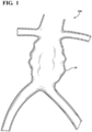
- Delivery systems for deployment of expandable devices or implants are disclosed herein which utilize multiple percutaneous access sites for treating a variety of vascular diseases, as shown in FIG. 1 , for example, for treating aneurysms 10 along a vessel 100,
- FIG. 1 vascular diseases
- FIG. 1 Delivery systems for deployment of expandable devices or implants are disclosed herein which utilize multiple percutaneous access sites for treating a variety of vascular diseases, as shown in FIG. 1 , for example, for treating aneurysms 10 along a vessel 100
- AAA abdominal aortic aneurysm
- the devices, systems and methods described herein are not limited to treatment of AAA's and can be applied to delivery of any endoluminally deliverable device, component or tool for treatment of disease in other parts of human vasculature.
- Examples of stent grafts usable with delivery systems in accordance with the present disclosure are disclosed in U.S. Patent 6,042,605 to Martin et. al.
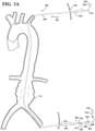
- a delivery system is shown in a configuration utilizing two or more percutaneous access sites 102, 104.
- the delivery system allows push-pull positioning and delivery of an expandable device at a vascular treatment site through manipulation of at least two portions or members of the delivery system from outside of the body from respective access sites.
- the delivery system can include first and second introducer sheaths 202, 204 to facilitate introduction of surgical implements through respective access sites 102, 104.
- the delivery system includes a guidewire 206 that can be routed through a portion of vasculature to be treated in a "body floss" or "through-and-through” access configuration, wherein opposite terminal ends 205, 207 of the guidewire 206 extend outside of the body from respective percutaneous access sites 102, 104 via the first and second introducer sheaths 202, 204.
- a delivery system for endoluminal delivery of an implantable medical device can include elongated first and second catheters extending through respective first and second percutaneous access points and releasably coupled to each other at leading ends thereof to allow a push-pull or a pull-pull positioning of the implantable medical device prior to full deployment at the treatment site.
- a first catheter generally indicated at 300, includes a leading end 306 and an opposite trailing end 322.
- the first catheter 300 has a guidewire lumen 310 through which a guidewire 206 can be routed.
- a first end 205 of the guidewire 206 can be inserted into the guidewire lumen 310 at the leading end 306 of the first catheter 300.
- the leading end 306 of the first catheter 300 can be fed into the vasculature through the first access site 102 via the first introducer sheath 202.
- the first catheter 300 can then be pushed along the guidewire 206 in the direction indicated at 302 until the leading end 306 exits the second access site 104.
- the trailing end 322 of the first catheter 300 remains outside of the body and extends from the first access site 102 via the first introducer sheath 202. In this configuration, the catheter 300 can be maneuvered by pushing or pulling the leading end 306 and trailing ends 322 of the first catheter 300 from outside of the body.
- the catheter 300 can be inserted through the second access site 104 via the second introducer sheath 204, translated in a retrograde direction opposite the direction indicated at 302, and out of the first access site 102.
- transfer of the leading end 306 between the first access site 102 and second access site 104 can be facilitated with a snare. This can be helpful if the catheter has a low bending or column strength such that it can not be effectively navigated between access sites by only pushing on one end of the catheter from outside the body.
- a second catheter generally indicated at 400, includes a leading end 406 and an opposite trailing end 422.
- the second catheter 400 has a guidewire lumen 410 for receiving the guidewire 206 therethrough.
- the second end 207 of the guidewire 206 can be inserted into the guidewire lumen 410 at the leading end 406 of the second catheter 400.
- the second catheter 400 can be pushed along the guidewire 206 until the leading ends 306, 406 engage.
- An expandable device can be releasably coupled to one of the first and second catheters at or near the leading end thereof.
- the expandable device can be releasably maintained or radially compressed toward a delivery configuration for endoluminal delivery by any suitable constraining means, such as a film constraining sleeve, a constraining tether or lattice, retractable sheath and the like.
- a suitable constraining means such as a film constraining sleeve, a constraining tether or lattice, retractable sheath and the like.
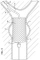
- an expandable device 500 is disposed at or near the leading end 406 of the second catheter 400.
- the expandable device 500 is compressed and held toward the delivery configuration by a constraining sleeve 502 extending about the expandable device 500 and having opposite ends or portions held together by a release line 504.
- the release line 504 can be disengaged from the constraining sleeve 502 to allow the device 500 to expand radially outwardly toward an unconstrained state or a partially unconstrained state or otherwise toward engagement with surrounding vessel walls at the treatment site.
- one or more constraining means or combination of constraining means can be configured to allow staged expansion through one or more intermediate expanded states prior to full deployment.
- An example of means for releasably constraining a device for endoluminal delivery is provided in U.S. Patent 6,352,561 to Leopold et al.
- the leading ends 306, 406 of the first and second catheters 300, 400 can be configured for matingly engaging or coupling to each other. Further, the leading ends 306, 406 can be configured for releasably coupling to each other. Coupling of the leading ends can be achieved by a variety of coupling arrangements. Non-limiting examples of coupling arrangements can include press fitting, threads, ball and detent, articulating clips or jaws, hook and loop, and magnetic.
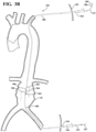
- the leading ends 306, 406 of the first and second catheters 300, 400 can be coupled to each other extracorporeal , as shown in FIG. 3A . Alternatively, the first and second catheters 300, 400 can be inserted into respective first and second access sites 102, 104 and the leading ends 306, 406 can be coupled in situ at or around the treatment site, as shown in FIG. 3B .
- trailing ends 322, 422 of the first and second catheters 300, 400 outside of the body can be pushed, pulled and rotated to axially and rotatably position the expandable device 500 at the treatment site.
- the expandable device 500 can be fully deployed to engage the surrounding vessel walls at the treatment site, as shown in FIG. 8 .
- Leading ends of first and second catheters can be coupled by providing an expandable device in a delivery configuration on a leading end of one of the first and second catheters and partially deploying the expandable device toward releasable engagement with a leading end of the other of the first and second catheters.
- the implantable prosthesis can be at least partially constrained along an outer wall of one of the first and second catheters and at least partially constrained along an inner wall of one of the first and second catheters, thereby forming a releasable connection between the first and second catheters.
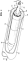
- an expandable device 500 is disposed at or near the leading end 406 of the second catheter 400.
- the expandable device 500 extends along an outer surface 428 of the second catheter 400 at or near the leading end 406 of the second catheter 400.
- the expandable device 500 is compressed and held toward the delivery configuration by a constraining sleeve 502 held together by a release line 504.
- the release line 504 can be disengaged from the constraining sleeve 502 to allow at least a portion of the device 500 to expand radially outwardly toward engagement with the leading end 306 of the first catheter 300.
- the leading end 306 of the first catheter 300 can include a bore 360 defined by an inner surface 362.
- the inner surface 362 can be generally annular for receiving therein the leading end 406 of the second catheter 400 and the constrained expandable device 500 supported thereon.
- disengagement of the release line 504 from the constraining sleeve 502 allows at least a portion of the device 500 to expand radially outwardly toward engagement with the inner surface 362 at the leading end 306 of the first catheter 300.
- a partially expanded portion 506 of the expandable device 500 has an engagement length measured by the length of the partially expanded portion 506 engaged with the inner surface 362 to create a releasable interconnection between the first and second catheters 300, 400.
- a remaining constrained portion 508 of the expandable device 500 may at least partially extend in the leading end 306 of the first catheter 300.
- the partially expanded portion 506 should apply sufficient outward radial force against the inner surface 362 to form a frictional coupling between the first and second catheters 300, 400 that allows, in one configuration, the first and second catheters 300, 400 to be pushed and/or pulled and/or rotated to axially and/or rotatably position the expandable device 500 at the treatment site.
- the coupling formed by the engagement between the partially expanded portion 506 and the inner surface 362 is releasable to allow decoupling and separation of the first and second catheters 300, 400.
- An opened section of the constraining sleeve 502 along the partially expanded portion 506 can be configured to remain between the first catheter inner wall and the expandable device 500.
- the constraining sleeve or portions thereof can be configured to be completely removed after deployment of the expandable device at the treatment site.
- the inner surface 362 can be configured to enhance the engagement or coupling between the first catheter 300 and second catheter 400.
- the inner surface 362 can include a texture or a rubber-like coating or layer to increase friction between the expandable device and the inner surface.
- the inner surface 362 can have cross-sectional profile that corresponds with or otherwise forms an interference engagement with an outer profile of the expandable device 500.
- trailing ends 322, 422 of the first and second catheters 300, 400 outside of the body can be pushed, pulled and rotated to axially and rotatably position the expandable device 500 at the treatment site.
- the expandable device 500 can be fully deployed to engage the surrounding vessel walls at the treatment site, as shown in FIG. 8 .
- the constraining sleeve 502 can be opened by displacing the release line 504 from the constraining sleeve 502 to allow the remaining constrained portion 508 to expand toward engagement with surrounding vessel walls on a first side 91 of an aneurysm 10 at the treatment side, as shown in FIG. 7A .
- the first catheter 300 can be displaced proximally or away from the second catheter 400, as indicated at arrow 602, to overcome the frictional engagement between the expandable device 500 and the inner surface 362.
- the displacement of the first catheter 300 away from the second catheter 400 allows the partially expanded portion 506 of the expandable device 500 to expand toward engagement with surrounding vessel walls on a second side 92 of the aneurysm 10, thereby completing exclusion of the aneurysm 10 from normal blood flow through the vessel, as shown in FIG. 8 .
- the first catheter 300 can be displaced proximally or away from the second catheter 400, as indicated at arrow 602, to overcome the releasable connection between the first and second catheters 300, 400 due to the frictional engagement between the expandable device 500 and the inner surface 362.
- the displacement of the first catheter 300 away from the second catheter 400 allows the partially expanded portion 506 of the expandable device 500 to expand toward engagement with surrounding vessel walls on the second side a2 of the aneurysm 10, as shown in FIG. 7B .
- the remaining constrained portion 508 of the expandable device 500 can be allowed to expand toward engagement with the surrounding vessel walls at the treatment site by displacing the release line 504 from the constraining sleeve 502, thereby completing exclusion of the aneurysm from normal blood flow through the vessel, as shown in FIG.8 .
- the first and second catheters 300, 400 can be removed from the treatment site and body from respective treatment sites (not shown).
- first and second catheters of the delivery system can be substantially more flexible than the other of the first and second catheters to facilitate traversing tortuous anatomy.
- a first catheter can be chosen to be a Pebax material with an outer diameter of 12.7 mm (0.5 inches) and an inner diameter of 1.0 mm (0.040 inches) with a durometer of X.
- a second catheter can be chosen to be a Pebax material with an outer diameter of 5.1 mm (0.2 inches) and an inner diameter of 1.0 mm (0.040 inches) with a durometer of .45X.
- Other parameters can be varied to achieve different ratios of one catheter to the other.
- the outer and inner diameters can be changed, a reinforcing member can be added to one or both of the catheters, or other suitable materials can be chosen.
- first and second catheters can have substantially no column strength or at least can be flexible so as to no be effectively pushable into and through the vasculature.
- a potential advantage of having a catheter with substantially no column strength is the catheter can be more easily fed through a vessel (e.g. pushed by blood in an antegrade fashion or pulled by a snare through tortuous anatomy).
- a first catheter can comprise a Pebax material with an outer diameter of about 8mm and an inner diameter of about 1.1 mm with a durometer of X.
- a second catheter can comprise a Pebax material with an outer diameter of approximately 4 mm and an inner diameter of about 1.1 mm with a durometer of about 0.5X.
- the second catheter can be an ePTFE tubular structure with desired outer and inner diameters.
- ePTFE tubular structure of approximately 8mm inner diameter and 8.14mm outer diameter is described below.
- the density of non-porous PTFE is about 2.2 g/cc; consequently, this film is about 86% porous.
- one or both of the first and second catheters can be tapered to facilitate entry into and movement through the vasculature.
- a delivery system can include a catheter having an elongated first portion and an elongated second portion, wherein a constrained device is mounted to the catheter in a constrained or delivery configuration between the first portion and second portion.
- the elongated first and second portions can be integral to form the catheter.
- the elongated first and second portions can be separate and connectable or releasably connectable to form the catheter.
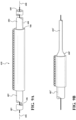
- a catheter 600 is shown in FIG. 9A having a first portion 602 and a second portion 604.
- the first portion 602 is elongated, extends along a first longitudinal axis 606 thereof, and terminates at a first end 603 of the catheter 600.
- the second portion 604 is elongated, extends along a second longitudinal axis 608 thereof, and terminates at a second end 605 of the catheter 600.
- An expandable device 700 is supported on a middle section 610 of the catheter 600 between the first portion 602 and second portion 604.
- the expandable device 700 can be radially constrained in a delivery configuration suitable for endoluminal delivery.
- the catheter 600 can be inserted into the vasculature, as described above in other embodiments, such that the first portion 602 extends outwardly from a first access site 102' via a first introducer sheath 202' and the second portion 604 extends outwardly from a second access site 104', optionally via a second introducer sheath 204'.
- the first and second portions 602, 604 extending outside of the body can be pushed, pulled and rotated to axially and rotatably position the expandable device 500 at the treatment site.
- one of the elongated first and second portions of the catheter can have a smaller diameter than the other of the elongated first and second portions.
- the second portion 604' of the catheter 600' can have a smaller diameter than the first portion 602' of the catheter 600'.
- one of the elongated first and second portions of the catheter can be substantially more flexible than the other of the elongated first and second portions of the catheter.
- one or both of the first and second portions of the catheter can have substantially no column strength or at least can be flexible so as to not be effectively pushable into and through the vasculature.
- first and second portions of the catheter can be axially compressible toward each other to cause the catheter and implant to buckle. This buckling, when combined with rotation of the catheter may be useful in correct and accurate placement of an endoluminal device.
- first and second portions of the catheter can be tapered toward the respective first and second ends to facilitate entry into and movement of the catheter through vasculature.
- one of the first and second catheters may in the form of an ePTFE fiber, wherein the fiber may not have an inner lumen.
- a delivery system is shown utilizing both trans-apical access and trans-femoral access sites, which allows push-pull positioning and delivery of an expandable implant inside of, at or near the heart through manipulation of at least two portions or members of the delivery system from outside of the body from the respective trans-apical and trans-femoral access sites.
- the delivery system can, for example, be used to deploy an endoprosthetic device, such as a stent graft for treating the ascending portion of the aortic arch or a valve device for replacing a failing valve.
- an endoprosthetic device such as a stent graft for treating the ascending portion of the aortic arch or a valve device for replacing a failing valve.
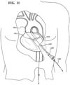
- a guidewire 1206 can be inserted through the trans-apical access site and into the left ventricle 1010 of the heart 1100, as shown in FIG. 10 .
- the guidewire 1206 can be routed through the aortic valve 1012, the aorta 1014, a femoral artery of one of the legs, and out of the body via the trans-femoral access site (not shown), resulting in a "body floss" or "through-and-through” access configuration, wherein opposite terminal ends 1205, 1207 of the guidewire 1206 extend outside of the body from respective trans-apical and trans-femoral access sites 1102, 1104, as shown in FIG. 11 .
- the guidewire 1206 can be tensioned by pulling on the opposite ends 1205, 1207 of the guidewire 1206, as illustrated by the arrows "a" and "b” in FIG. 11 , to cause the guidewire 1206 to extend along the inside radius of the aortic arch.
- a first introducer sheath 1202 can be inserted over the guidewire 1206 and into the heart 1100 via the trans-apical access site to facilitate introduction of surgical implements therethrough during the procedure.
- a second introducer sheath (not shown) can be inserted over the guidewire 1206 to facilitate femoral introduction of surgical implements through the trans-femoral access site.
- a first catheter generally indicated at 1300, includes a leading end 1306 and an opposite trailing end 1322.
- the first catheter 1300 has a guidewire lumen 1310 through which the guidewire 1206 can be routed.
- a first end 1205 of the guidewire 1206 can be inserted into the guidewire lumen 1310 at the leading end 1306 of the first catheter 1300.
- the leading end 1306 of the first catheter 1300 can be fed into the vasculature through the trans-apical access site 1102 via the first introducer sheath 1202.
- the first catheter 1300 can then be pushed along the guidewire 1206 in the direction indicated at 1302 until the leading end 1306 exits the trans-femoral access site (not illustrated).
- the trailing end 1322 of the first catheter 1300 remains outside of the body and extends from the first access site 1102 via the first introducer sheath 1202.
- the catheter 1300 can be maneuvered by pushing or pulling the leading 1306 and trailing 1322 ends of the first catheter 1300 from outside of the body.
- optionally tensioning the guidewire 1206, as illustrated in FIG. 11 can result in the first catheter 300, or any other implement delivered over the guidewire 1206, tracking and remaining along the inside radius of the aortic arch, as shown in FIGS 12-14 .
- a second catheter generally indicated at 1400, includes a leading end 1406 and an opposite trailing end 1422.
- the second catheter 1400 has a guidewire lumen 1410 for receiving the guidewire 1206 therethrough.
- the second end 1207 of the guidewire 1206 can be inserted into the guidewire lumen 1410 at the leading end 1406 of the second catheter 1400.
- the second catheter 1400 can be pushed along the guidewire 1206 until the leading ends 306, 306 engage.
- An endoprosthetic device for treating a failing heart valve or disease along the ascending portion of the aorta or aortic arch can be releasably coupled to one of the first and second catheters at or near the leading end thereof.
- the endoprosthetic device can be releasably maintained or radially compressed toward a delivery configuration for endoluminal delivery by any suitable constraining means, such as a film constraining sleeve, a constraining tether or lattice, retractable sheath and the like.
- one or more constraining means or combination of constraining means can be configured to allow staged expansion through one or more intermediate expanded states leading to full deployment. As shown in FIG. 12 , for example, a device 1500 is releasably held in a delivery configuration coupled at or near the leading end 1406 of the second catheter 1400.
- the leading ends 1306, 1406 of the first and second catheters 1300, 1400 can be configured for matingly engaging or coupling to each other. Further, the leading ends 1306, 1406 can be configured for releasably coupling to each other. The leading ends 1306, 1406 of the first and second catheters 1300, 1400 can be coupled to each other extra corpeal or in situ. Once the leading ends 1306, 1406 are coupled, the trailing ends 1322, 1422 of the first and second catheters 1300, 1400 can be accessed outside of the body from the respective trans-apical 1102 and trans-femoral 1202 access sites 1102, 1104 and pushed, pulled and rotated to axially and rotatably position the device 1500 at the treatment site, as shown in FIG. 13 . After the device 1500 has been positioned at a desirable location and orientation at the treatment site, the device 1500 can be fully deployed to engage the surrounding tissues at the treatment site.
- a filter 1800 may be deployed to filter blood entering the branch arteries 1016, 1018, 1020.
Landscapes
- Health & Medical Sciences (AREA)
- Biomedical Technology (AREA)
- Engineering & Computer Science (AREA)
- Life Sciences & Earth Sciences (AREA)
- Cardiology (AREA)
- Animal Behavior & Ethology (AREA)
- Veterinary Medicine (AREA)
- Public Health (AREA)
- Heart & Thoracic Surgery (AREA)
- General Health & Medical Sciences (AREA)
- Transplantation (AREA)
- Oral & Maxillofacial Surgery (AREA)
- Vascular Medicine (AREA)
- Surgery (AREA)
- Molecular Biology (AREA)
- Medical Informatics (AREA)
- Nuclear Medicine, Radiotherapy & Molecular Imaging (AREA)
- Pathology (AREA)
- Gastroenterology & Hepatology (AREA)
- Prostheses (AREA)
- Media Introduction/Drainage Providing Device (AREA)
- Surgical Instruments (AREA)
Applications Claiming Priority (3)
| Application Number | Priority Date | Filing Date | Title |
|---|---|---|---|
| US201461988038P | 2014-05-02 | 2014-05-02 | |
| US14/701,508 US10765544B2 (en) | 2014-05-02 | 2015-04-30 | Push and pull medical device delivery system |
| PCT/US2015/028903 WO2015168627A1 (en) | 2014-05-02 | 2015-05-01 | Push and pull medical device delivery system |
Publications (2)
| Publication Number | Publication Date |
|---|---|
| EP3137021A1 EP3137021A1 (en) | 2017-03-08 |
| EP3137021B1 true EP3137021B1 (en) | 2024-06-26 |
Family
ID=54354355
Family Applications (1)
| Application Number | Title | Priority Date | Filing Date |
|---|---|---|---|
| EP15722637.4A Active EP3137021B1 (en) | 2014-05-02 | 2015-05-01 | Push and pull medical device delivery system |
Country Status (9)
Families Citing this family (17)
| Publication number | Priority date | Publication date | Assignee | Title |
|---|---|---|---|---|
| US9782282B2 (en) | 2011-11-14 | 2017-10-10 | W. L. Gore & Associates, Inc. | External steerable fiber for use in endoluminal deployment of expandable devices |
| US9375308B2 (en) | 2012-03-13 | 2016-06-28 | W. L. Gore & Associates, Inc. | External steerable fiber for use in endoluminal deployment of expandable devices |
| US10363040B2 (en) | 2014-05-02 | 2019-07-30 | W. L. Gore & Associates, Inc. | Anastomosis devices |
| US11439396B2 (en) | 2014-05-02 | 2022-09-13 | W. L. Gore & Associates, Inc. | Occluder and anastomosis devices |
| US10433993B2 (en) | 2017-01-20 | 2019-10-08 | Medtronic Vascular, Inc. | Valve prosthesis having a radially-expandable sleeve integrated thereon for delivery and prevention of paravalvular leakage |
| WO2018165358A1 (en) | 2017-03-08 | 2018-09-13 | W. L. Gore & Associates, Inc. | Steering wire attach for angulation |
| US11724075B2 (en) * | 2017-04-18 | 2023-08-15 | W. L. Gore & Associates, Inc. | Deployment constraining sheath that enables staged deployment by device section |
| WO2019055311A1 (en) * | 2017-09-12 | 2019-03-21 | W. L. Gore & Associates, Inc. | SUBSTRATE WITH ROTARY SPACERS FOR MEDICAL DEVICE |
| WO2019165213A1 (en) | 2018-02-22 | 2019-08-29 | Medtronic Vascular, Inc. | Prosthetic heart valve delivery systems and methods |
| CN112004504B (zh) * | 2018-04-12 | 2025-02-11 | 柯惠有限合伙公司 | 支架递送系统和医疗装置递送系统 |
| EP3817687A1 (en) * | 2018-07-06 | 2021-05-12 | Muffin Incorporated d/b/a Cook Advanced Technologies | Storage devices, loading devices, delivery systems kits, and associated methods |
| CN108852466B (zh) * | 2018-07-13 | 2021-07-06 | 湖南埃普特医疗器械有限公司 | 取栓器 |
| WO2020046365A1 (en) * | 2018-08-31 | 2020-03-05 | W. L. Gore & Associates, Inc. | Apparatus, system, and method for steering an implantable medical device |
| US11065139B2 (en) | 2019-01-08 | 2021-07-20 | Covidien Lp | Apparatuses for stent delivery and positioning to cover an access site |
| US11229541B2 (en) * | 2019-01-08 | 2022-01-25 | Covidien Lp | Methods for stent delivery and positioning to cover an access site |
| US11065140B2 (en) * | 2019-01-08 | 2021-07-20 | Covidien Lp | Rotatable stent delivery apparatus to cover access site |
| CN116135245A (zh) * | 2023-03-13 | 2023-05-19 | 深圳市爱博医疗机器人有限公司 | 细长型医疗器械的递送装置 |
Citations (3)
| Publication number | Priority date | Publication date | Assignee | Title |
|---|---|---|---|---|
| US20040002714A1 (en) * | 2002-06-06 | 2004-01-01 | Mitchell Weiss | Method for installing a stent graft |
| US20090054836A1 (en) * | 2007-08-20 | 2009-02-26 | Medtronic Vascular, Inc. | Method and Apparatus for Treating Stenoses at Bifurcated Regions |
| US20090204083A1 (en) * | 2008-02-13 | 2009-08-13 | Medtronic Vascular, Inc. | Method and Apparatus for Treating Stenoses at Bifurcated Regions |
Family Cites Families (14)
| Publication number | Priority date | Publication date | Assignee | Title |
|---|---|---|---|---|
| US5591228A (en) | 1995-05-09 | 1997-01-07 | Edoga; John K. | Methods for treating abdominal aortic aneurysms |
| US6042605A (en) | 1995-12-14 | 2000-03-28 | Gore Enterprose Holdings, Inc. | Kink resistant stent-graft |
| US6352561B1 (en) | 1996-12-23 | 2002-03-05 | W. L. Gore & Associates | Implant deployment apparatus |
| US5948017A (en) | 1997-10-12 | 1999-09-07 | Taheri; Syde A. | Modular graft assembly |
| US6626939B1 (en) * | 1997-12-18 | 2003-09-30 | Boston Scientific Scimed, Inc. | Stent-graft with bioabsorbable structural support |
| US7850643B1 (en) * | 1999-09-27 | 2010-12-14 | Advanced Cardiovascular Systems, Inc. | Drug diffusion barriers for a catheter assembly |
| US6849087B1 (en) | 1999-10-06 | 2005-02-01 | Timothy A. M. Chuter | Device and method for staged implantation of a graft for vascular repair |
| US6899727B2 (en) * | 2001-01-22 | 2005-05-31 | Gore Enterprise Holdings, Inc. | Deployment system for intraluminal devices |
| US8128680B2 (en) * | 2005-01-10 | 2012-03-06 | Taheri Laduca Llc | Apparatus and method for deploying an implantable device within the body |
| EP3789069B1 (en) * | 2008-02-05 | 2024-04-03 | Silk Road Medical, Inc. | Systems for establishing retrograde carotid arterial blood flow |
| JP2012515578A (ja) * | 2009-01-23 | 2012-07-12 | エンドールミナル サイエンシーズ プロプライエタリー リミテッド | 血管内デバイスならびに関連のシステムおよび方法 |
| WO2011106547A2 (en) | 2010-02-26 | 2011-09-01 | Silk Road Medical, Inc. | Systems and methods for transcatheter aortic valve treatment |
| EP3053545B1 (en) * | 2011-04-28 | 2019-09-18 | Cook Medical Technologies LLC | Apparatus for facilitating deployment of an endoluminal prosthesis |
| CN105007860B (zh) * | 2013-01-08 | 2017-05-10 | 恩多斯潘有限公司 | 在植入期间支架移植物迁移的最小化 |
-
2015
- 2015-04-30 US US14/701,508 patent/US10765544B2/en active Active
- 2015-05-01 WO PCT/US2015/028903 patent/WO2015168627A1/en active Application Filing
- 2015-05-01 CN CN201580023481.0A patent/CN106456327B/zh active Active
- 2015-05-01 JP JP2016563460A patent/JP6985012B2/ja active Active
- 2015-05-01 AU AU2015252850A patent/AU2015252850B2/en active Active
- 2015-05-01 CA CA2945185A patent/CA2945185C/en active Active
- 2015-05-01 EP EP15722637.4A patent/EP3137021B1/en active Active
- 2015-05-01 KR KR1020167032150A patent/KR20160147846A/ko not_active Ceased
- 2015-05-01 ES ES15722637T patent/ES2986347T3/es active Active
-
2020
- 2020-02-27 JP JP2020031949A patent/JP7074787B2/ja active Active
Patent Citations (3)
| Publication number | Priority date | Publication date | Assignee | Title |
|---|---|---|---|---|
| US20040002714A1 (en) * | 2002-06-06 | 2004-01-01 | Mitchell Weiss | Method for installing a stent graft |
| US20090054836A1 (en) * | 2007-08-20 | 2009-02-26 | Medtronic Vascular, Inc. | Method and Apparatus for Treating Stenoses at Bifurcated Regions |
| US20090204083A1 (en) * | 2008-02-13 | 2009-08-13 | Medtronic Vascular, Inc. | Method and Apparatus for Treating Stenoses at Bifurcated Regions |
Also Published As
| Publication number | Publication date |
|---|---|
| KR20160147846A (ko) | 2016-12-23 |
| ES2986347T3 (es) | 2024-11-11 |
| WO2015168627A1 (en) | 2015-11-05 |
| JP7074787B2 (ja) | 2022-05-24 |
| CA2945185A1 (en) | 2015-11-05 |
| JP2020096942A (ja) | 2020-06-25 |
| AU2015252850B2 (en) | 2018-02-22 |
| US20150313738A1 (en) | 2015-11-05 |
| JP2017516520A (ja) | 2017-06-22 |
| EP3137021A1 (en) | 2017-03-08 |
| US10765544B2 (en) | 2020-09-08 |
| CA2945185C (en) | 2020-07-07 |
| AU2015252850A1 (en) | 2016-10-27 |
| CN106456327A (zh) | 2017-02-22 |
| JP6985012B2 (ja) | 2021-12-22 |
| CN106456327B (zh) | 2021-06-01 |
Similar Documents
| Publication | Publication Date | Title |
|---|---|---|
| EP3137021B1 (en) | Push and pull medical device delivery system | |
| US10806563B2 (en) | Preloaded wire for endoluminal device | |
| JP6659753B2 (ja) | 予めカニューレが挿入された開窓部 | |
| JP6522483B2 (ja) | 管腔内装置用の予め装着されたワイヤ | |
| JP5722764B2 (ja) | 分岐型移植片の展開システムおよび展開方法 | |
| EP2117631B1 (en) | Dual concentric guidewire and methods of bifurcated graft deployment | |
| EP2985007B1 (en) | Preloaded wire for endoluminal device | |
| JP2010503497A (ja) | 多重に分割されたグラフト展開システム | |
| US10500079B2 (en) | Preloaded branch wire loop constraint | |
| JP2023133439A (ja) | ロックワイヤルーメンを有する低プロフィル送達システム | |
| EP3245986B1 (en) | Wire retention and release mechanisms | |
| AU2015261727B2 (en) | Preloaded wire for endoluminal device |
Legal Events
| Date | Code | Title | Description |
|---|---|---|---|
| STAA | Information on the status of an ep patent application or granted ep patent |
Free format text: STATUS: THE INTERNATIONAL PUBLICATION HAS BEEN MADE |
|
| PUAI | Public reference made under article 153(3) epc to a published international application that has entered the european phase |
Free format text: ORIGINAL CODE: 0009012 |
|
| STAA | Information on the status of an ep patent application or granted ep patent |
Free format text: STATUS: REQUEST FOR EXAMINATION WAS MADE |
|
| 17P | Request for examination filed |
Effective date: 20161004 |
|
| AK | Designated contracting states |
Kind code of ref document: A1 Designated state(s): AL AT BE BG CH CY CZ DE DK EE ES FI FR GB GR HR HU IE IS IT LI LT LU LV MC MK MT NL NO PL PT RO RS SE SI SK SM TR |
|
| AX | Request for extension of the european patent |
Extension state: BA ME |
|
| DAV | Request for validation of the european patent (deleted) | ||
| DAX | Request for extension of the european patent (deleted) | ||
| REG | Reference to a national code |
Ref country code: HK Ref legal event code: DE Ref document number: 1233897 Country of ref document: HK |
|
| STAA | Information on the status of an ep patent application or granted ep patent |
Free format text: STATUS: EXAMINATION IS IN PROGRESS |
|
| 17Q | First examination report despatched |
Effective date: 20210322 |
|
| STAA | Information on the status of an ep patent application or granted ep patent |
Free format text: STATUS: EXAMINATION IS IN PROGRESS |
|
| RAP3 | Party data changed (applicant data changed or rights of an application transferred) |
Owner name: W.L. GORE & ASSOCIATES, INC. |
|
| GRAP | Despatch of communication of intention to grant a patent |
Free format text: ORIGINAL CODE: EPIDOSNIGR1 |
|
| STAA | Information on the status of an ep patent application or granted ep patent |
Free format text: STATUS: GRANT OF PATENT IS INTENDED |
|
| INTG | Intention to grant announced |
Effective date: 20240115 |
|
| P01 | Opt-out of the competence of the unified patent court (upc) registered |
Effective date: 20240319 |
|
| GRAS | Grant fee paid |
Free format text: ORIGINAL CODE: EPIDOSNIGR3 |
|
| GRAA | (expected) grant |
Free format text: ORIGINAL CODE: 0009210 |
|
| STAA | Information on the status of an ep patent application or granted ep patent |
Free format text: STATUS: THE PATENT HAS BEEN GRANTED |
|
| AK | Designated contracting states |
Kind code of ref document: B1 Designated state(s): AL AT BE BG CH CY CZ DE DK EE ES FI FR GB GR HR HU IE IS IT LI LT LU LV MC MK MT NL NO PL PT RO RS SE SI SK SM TR |
|
| REG | Reference to a national code |
Ref country code: GB Ref legal event code: FG4D |
|
| REG | Reference to a national code |
Ref country code: CH Ref legal event code: EP |
|
| REG | Reference to a national code |
Ref country code: DE Ref legal event code: R096 Ref document number: 602015089055 Country of ref document: DE |
|
| PG25 | Lapsed in a contracting state [announced via postgrant information from national office to epo] |
Ref country code: BG Free format text: LAPSE BECAUSE OF FAILURE TO SUBMIT A TRANSLATION OF THE DESCRIPTION OR TO PAY THE FEE WITHIN THE PRESCRIBED TIME-LIMIT Effective date: 20240626 |
|
| PG25 | Lapsed in a contracting state [announced via postgrant information from national office to epo] |
Ref country code: HR Free format text: LAPSE BECAUSE OF FAILURE TO SUBMIT A TRANSLATION OF THE DESCRIPTION OR TO PAY THE FEE WITHIN THE PRESCRIBED TIME-LIMIT Effective date: 20240626 Ref country code: FI Free format text: LAPSE BECAUSE OF FAILURE TO SUBMIT A TRANSLATION OF THE DESCRIPTION OR TO PAY THE FEE WITHIN THE PRESCRIBED TIME-LIMIT Effective date: 20240626 |
|
| REG | Reference to a national code |
Ref country code: LT Ref legal event code: MG9D |
|
| PG25 | Lapsed in a contracting state [announced via postgrant information from national office to epo] |
Ref country code: GR Free format text: LAPSE BECAUSE OF FAILURE TO SUBMIT A TRANSLATION OF THE DESCRIPTION OR TO PAY THE FEE WITHIN THE PRESCRIBED TIME-LIMIT Effective date: 20240927 |
|
| PG25 | Lapsed in a contracting state [announced via postgrant information from national office to epo] |
Ref country code: LV Free format text: LAPSE BECAUSE OF FAILURE TO SUBMIT A TRANSLATION OF THE DESCRIPTION OR TO PAY THE FEE WITHIN THE PRESCRIBED TIME-LIMIT Effective date: 20240626 |
|
| REG | Reference to a national code |
Ref country code: NL Ref legal event code: MP Effective date: 20240626 |
|
| PG25 | Lapsed in a contracting state [announced via postgrant information from national office to epo] |
Ref country code: NO Free format text: LAPSE BECAUSE OF FAILURE TO SUBMIT A TRANSLATION OF THE DESCRIPTION OR TO PAY THE FEE WITHIN THE PRESCRIBED TIME-LIMIT Effective date: 20240926 Ref country code: LV Free format text: LAPSE BECAUSE OF FAILURE TO SUBMIT A TRANSLATION OF THE DESCRIPTION OR TO PAY THE FEE WITHIN THE PRESCRIBED TIME-LIMIT Effective date: 20240626 Ref country code: HR Free format text: LAPSE BECAUSE OF FAILURE TO SUBMIT A TRANSLATION OF THE DESCRIPTION OR TO PAY THE FEE WITHIN THE PRESCRIBED TIME-LIMIT Effective date: 20240626 Ref country code: GR Free format text: LAPSE BECAUSE OF FAILURE TO SUBMIT A TRANSLATION OF THE DESCRIPTION OR TO PAY THE FEE WITHIN THE PRESCRIBED TIME-LIMIT Effective date: 20240927 Ref country code: FI Free format text: LAPSE BECAUSE OF FAILURE TO SUBMIT A TRANSLATION OF THE DESCRIPTION OR TO PAY THE FEE WITHIN THE PRESCRIBED TIME-LIMIT Effective date: 20240626 Ref country code: BG Free format text: LAPSE BECAUSE OF FAILURE TO SUBMIT A TRANSLATION OF THE DESCRIPTION OR TO PAY THE FEE WITHIN THE PRESCRIBED TIME-LIMIT Effective date: 20240626 Ref country code: RS Free format text: LAPSE BECAUSE OF FAILURE TO SUBMIT A TRANSLATION OF THE DESCRIPTION OR TO PAY THE FEE WITHIN THE PRESCRIBED TIME-LIMIT Effective date: 20240926 |
|
| REG | Reference to a national code |
Ref country code: ES Ref legal event code: FG2A Ref document number: 2986347 Country of ref document: ES Kind code of ref document: T3 Effective date: 20241111 |
|
| PG25 | Lapsed in a contracting state [announced via postgrant information from national office to epo] |
Ref country code: NL Free format text: LAPSE BECAUSE OF FAILURE TO SUBMIT A TRANSLATION OF THE DESCRIPTION OR TO PAY THE FEE WITHIN THE PRESCRIBED TIME-LIMIT Effective date: 20240626 |
|
| REG | Reference to a national code |
Ref country code: AT Ref legal event code: MK05 Ref document number: 1697087 Country of ref document: AT Kind code of ref document: T Effective date: 20240626 |
|
| PG25 | Lapsed in a contracting state [announced via postgrant information from national office to epo] |
Ref country code: NL Free format text: LAPSE BECAUSE OF FAILURE TO SUBMIT A TRANSLATION OF THE DESCRIPTION OR TO PAY THE FEE WITHIN THE PRESCRIBED TIME-LIMIT Effective date: 20240626 |
|
| REG | Reference to a national code |
Ref country code: HK Ref legal event code: WD Ref document number: 1233897 Country of ref document: HK |
|
| PG25 | Lapsed in a contracting state [announced via postgrant information from national office to epo] |
Ref country code: PT Free format text: LAPSE BECAUSE OF FAILURE TO SUBMIT A TRANSLATION OF THE DESCRIPTION OR TO PAY THE FEE WITHIN THE PRESCRIBED TIME-LIMIT Effective date: 20241028 |
|
| PG25 | Lapsed in a contracting state [announced via postgrant information from national office to epo] |
Ref country code: PT Free format text: LAPSE BECAUSE OF FAILURE TO SUBMIT A TRANSLATION OF THE DESCRIPTION OR TO PAY THE FEE WITHIN THE PRESCRIBED TIME-LIMIT Effective date: 20241028 |
|
| PG25 | Lapsed in a contracting state [announced via postgrant information from national office to epo] |
Ref country code: PL Free format text: LAPSE BECAUSE OF FAILURE TO SUBMIT A TRANSLATION OF THE DESCRIPTION OR TO PAY THE FEE WITHIN THE PRESCRIBED TIME-LIMIT Effective date: 20240626 |
|
| PG25 | Lapsed in a contracting state [announced via postgrant information from national office to epo] |
Ref country code: EE Free format text: LAPSE BECAUSE OF FAILURE TO SUBMIT A TRANSLATION OF THE DESCRIPTION OR TO PAY THE FEE WITHIN THE PRESCRIBED TIME-LIMIT Effective date: 20240626 |
|
| PG25 | Lapsed in a contracting state [announced via postgrant information from national office to epo] |
Ref country code: AT Free format text: LAPSE BECAUSE OF FAILURE TO SUBMIT A TRANSLATION OF THE DESCRIPTION OR TO PAY THE FEE WITHIN THE PRESCRIBED TIME-LIMIT Effective date: 20240626 Ref country code: IS Free format text: LAPSE BECAUSE OF FAILURE TO SUBMIT A TRANSLATION OF THE DESCRIPTION OR TO PAY THE FEE WITHIN THE PRESCRIBED TIME-LIMIT Effective date: 20241026 |
|
| PG25 | Lapsed in a contracting state [announced via postgrant information from national office to epo] |
Ref country code: CZ Free format text: LAPSE BECAUSE OF FAILURE TO SUBMIT A TRANSLATION OF THE DESCRIPTION OR TO PAY THE FEE WITHIN THE PRESCRIBED TIME-LIMIT Effective date: 20240626 |
|
| PG25 | Lapsed in a contracting state [announced via postgrant information from national office to epo] |
Ref country code: RO Free format text: LAPSE BECAUSE OF FAILURE TO SUBMIT A TRANSLATION OF THE DESCRIPTION OR TO PAY THE FEE WITHIN THE PRESCRIBED TIME-LIMIT Effective date: 20240626 Ref country code: SK Free format text: LAPSE BECAUSE OF FAILURE TO SUBMIT A TRANSLATION OF THE DESCRIPTION OR TO PAY THE FEE WITHIN THE PRESCRIBED TIME-LIMIT Effective date: 20240626 |
|
| PG25 | Lapsed in a contracting state [announced via postgrant information from national office to epo] |
Ref country code: SM Free format text: LAPSE BECAUSE OF FAILURE TO SUBMIT A TRANSLATION OF THE DESCRIPTION OR TO PAY THE FEE WITHIN THE PRESCRIBED TIME-LIMIT Effective date: 20240626 |
|
| PG25 | Lapsed in a contracting state [announced via postgrant information from national office to epo] |
Ref country code: SM Free format text: LAPSE BECAUSE OF FAILURE TO SUBMIT A TRANSLATION OF THE DESCRIPTION OR TO PAY THE FEE WITHIN THE PRESCRIBED TIME-LIMIT Effective date: 20240626 Ref country code: SK Free format text: LAPSE BECAUSE OF FAILURE TO SUBMIT A TRANSLATION OF THE DESCRIPTION OR TO PAY THE FEE WITHIN THE PRESCRIBED TIME-LIMIT Effective date: 20240626 Ref country code: RO Free format text: LAPSE BECAUSE OF FAILURE TO SUBMIT A TRANSLATION OF THE DESCRIPTION OR TO PAY THE FEE WITHIN THE PRESCRIBED TIME-LIMIT Effective date: 20240626 Ref country code: PL Free format text: LAPSE BECAUSE OF FAILURE TO SUBMIT A TRANSLATION OF THE DESCRIPTION OR TO PAY THE FEE WITHIN THE PRESCRIBED TIME-LIMIT Effective date: 20240626 Ref country code: IS Free format text: LAPSE BECAUSE OF FAILURE TO SUBMIT A TRANSLATION OF THE DESCRIPTION OR TO PAY THE FEE WITHIN THE PRESCRIBED TIME-LIMIT Effective date: 20241026 Ref country code: EE Free format text: LAPSE BECAUSE OF FAILURE TO SUBMIT A TRANSLATION OF THE DESCRIPTION OR TO PAY THE FEE WITHIN THE PRESCRIBED TIME-LIMIT Effective date: 20240626 Ref country code: CZ Free format text: LAPSE BECAUSE OF FAILURE TO SUBMIT A TRANSLATION OF THE DESCRIPTION OR TO PAY THE FEE WITHIN THE PRESCRIBED TIME-LIMIT Effective date: 20240626 Ref country code: AT Free format text: LAPSE BECAUSE OF FAILURE TO SUBMIT A TRANSLATION OF THE DESCRIPTION OR TO PAY THE FEE WITHIN THE PRESCRIBED TIME-LIMIT Effective date: 20240626 |
|
| REG | Reference to a national code |
Ref country code: DE Ref legal event code: R097 Ref document number: 602015089055 Country of ref document: DE |
|
| PG25 | Lapsed in a contracting state [announced via postgrant information from national office to epo] |
Ref country code: DK Free format text: LAPSE BECAUSE OF FAILURE TO SUBMIT A TRANSLATION OF THE DESCRIPTION OR TO PAY THE FEE WITHIN THE PRESCRIBED TIME-LIMIT Effective date: 20240626 |
|
| PLBE | No opposition filed within time limit |
Free format text: ORIGINAL CODE: 0009261 |
|
| STAA | Information on the status of an ep patent application or granted ep patent |
Free format text: STATUS: NO OPPOSITION FILED WITHIN TIME LIMIT |
|
| 26N | No opposition filed |
Effective date: 20250327 |
|
| PGFP | Annual fee paid to national office [announced via postgrant information from national office to epo] |
Ref country code: DE Payment date: 20250423 Year of fee payment: 11 |
|
| PGFP | Annual fee paid to national office [announced via postgrant information from national office to epo] |
Ref country code: GB Payment date: 20250423 Year of fee payment: 11 Ref country code: ES Payment date: 20250602 Year of fee payment: 11 |
|
| PGFP | Annual fee paid to national office [announced via postgrant information from national office to epo] |
Ref country code: IT Payment date: 20250423 Year of fee payment: 11 |
|
| PGFP | Annual fee paid to national office [announced via postgrant information from national office to epo] |
Ref country code: FR Payment date: 20250423 Year of fee payment: 11 |
|
| PGFP | Annual fee paid to national office [announced via postgrant information from national office to epo] |
Ref country code: IE Payment date: 20250424 Year of fee payment: 11 |