EP3135813B1 - Schallschutzvorrichtung für eine gleisanlage - Google Patents
Schallschutzvorrichtung für eine gleisanlage Download PDFInfo
- Publication number
- EP3135813B1 EP3135813B1 EP16185430.2A EP16185430A EP3135813B1 EP 3135813 B1 EP3135813 B1 EP 3135813B1 EP 16185430 A EP16185430 A EP 16185430A EP 3135813 B1 EP3135813 B1 EP 3135813B1
- Authority
- EP
- European Patent Office
- Prior art keywords
- sound insulation
- region
- sound
- fastening
- soundproofing
- Prior art date
- Legal status (The legal status is an assumption and is not a legal conclusion. Google has not performed a legal analysis and makes no representation as to the accuracy of the status listed.)
- Active
Links
Images




Classifications
-
- E—FIXED CONSTRUCTIONS
- E01—CONSTRUCTION OF ROADS, RAILWAYS, OR BRIDGES
- E01B—PERMANENT WAY; PERMANENT-WAY TOOLS; MACHINES FOR MAKING RAILWAYS OF ALL KINDS
- E01B19/00—Protection of permanent way against development of dust or against the effect of wind, sun, frost, or corrosion; Means to reduce development of noise
- E01B19/003—Means for reducing the development or propagation of noise
-
- E—FIXED CONSTRUCTIONS
- E01—CONSTRUCTION OF ROADS, RAILWAYS, OR BRIDGES
- E01B—PERMANENT WAY; PERMANENT-WAY TOOLS; MACHINES FOR MAKING RAILWAYS OF ALL KINDS
- E01B26/00—Tracks or track components not covered by any one of the preceding groups
- E01B26/005—Means for fixing posts, barriers, fences or the like to rails
-
- E—FIXED CONSTRUCTIONS
- E01—CONSTRUCTION OF ROADS, RAILWAYS, OR BRIDGES
- E01F—ADDITIONAL WORK, SUCH AS EQUIPPING ROADS OR THE CONSTRUCTION OF PLATFORMS, HELICOPTER LANDING STAGES, SIGNS, SNOW FENCES, OR THE LIKE
- E01F8/00—Arrangements for absorbing or reflecting air-transmitted noise from road or railway traffic
- E01F8/0005—Arrangements for absorbing or reflecting air-transmitted noise from road or railway traffic used in a wall type arrangement
- E01F8/0029—Arrangements for absorbing or reflecting air-transmitted noise from road or railway traffic used in a wall type arrangement with porous surfaces, e.g. concrete with porous fillers
Definitions
- the present invention relates to a soundproofing device for a track system, which soundproofing device comprises a soundproofing area and a fastening area for fastening to the track system.
- a soundproofing device to be attached to a track system which comprises a wall-shaped soundproofing element.
- the soundproofing element provides a soundproofing area which extends in the area of the track system next to the rails upwards and in the direction towards the rails.
- the soundproofing element is fastened to a rail via a plurality of carriers which provide a fastening region and are fixed in the lower region thereof and extend to the rails. These carriers have locking pins which engage in corresponding locking openings in the soundproofing element. To fix them to a rail, claws to be positioned over the rail base of a rail and locking screws that lock these are provided on these supports.
- a soundproofing device in which a plurality of supports which surround a rail foot of a rail and are fastened to the rail foot and are made of metal material and carry a plurality of sound insulation areas made of rubber material on both sides of a rail. These lip-like soundproofing areas extend towards the rail and lie against side surfaces of a rail head or a rail web connecting the rail head to the rail foot. When a train runs over it, the lip-like soundproofing areas positioned at the top in the vertical direction are deformed by a pulling wheel that rolls on the rail head.
- a soundproofing device for a track system according to the preamble of claim 1 is known, in which soundproofing elements are curved on both sides of a rail in the direction of the rail and have upward-running soundproofing areas and connecting them to a rail foot of the rail, and from the soundproofing elements or the Soundproofing areas of the same separately formed beams are defined on a track system.
- the soundproofing areas are constructed with a core made of rubber material, which is embedded at least on its side facing away from the rail in a rigid shell made of metal material or plastic material.
- the EP 1 905 901 A2 discloses a soundproofing device in which a soundproofing wall made of thermoplastic material, such as PE or PP, is arranged laterally next to the rails of a track system.
- a soundproofing device for a track system comprising a soundproofing area and a fastening area for fastening to a track system. It is further provided that the soundproofing area and the fastening area are formed on a soundproofing element made of rubber material and that the fastening area is designed for fastening the soundproofing element to a rail support arrangement carrying rails of a track system.
- the fastening area comprises a fastening fitting area that is adapted to the shape of a side end contour of a rail support arrangement and a plurality of fastening organ through openings.
- the soundproofing device is designed with a soundproofing element which takes over both the functionality for soundproofing, namely with its soundproofing area, and the functionality for fixing to a track system, namely with its fastening area.
- the attachment of additional supports on the soundproofing element on the one hand and on a rail on the other hand can be completely dispensed with.
- the fastening area is designed for fastening the soundproofing element to sleepers, which are largely used in rail systems as rail support arrangements.
- the fastening fitting area comprises a first fastening fitting area section to be positioned on an upper side of a rail support arrangement with a fastening fitting area underside and a second fastening fitting area section with a fastening fitting area end face to be positioned on a lateral face of a rail support arrangement, wherein fastening organ passage openings are preferably provided in the first fastening fitting area section.
- the soundproofing area is one of the Rails facing a track system to be positioned soundproofing side and a rear side to be positioned facing away from the rails of the track system, wherein the soundproofing area is preferably inclined in a height direction away from the fastening area towards the rear.
- the sound insulation area can be designed to obtain an optional sound insulation.
- An arrangement in which the soundproofing area is inclined in a height direction starting from the fastening area in the direction of the rear is particularly advantageous.
- the soundproofing device or its soundproofing area generally extends from the area where it is attached to a track system so that the soundproofing device is relatively close to the primary sound source, namely the tread run over by the wheels of rail vehicles of the respective rail head, but on the other hand an interference with the standard light space which is to be kept clear is avoided.
- a sound insulation formation can be provided on the sound insulation side, which in a particularly advantageous embodiment variant comprises a plurality of sound insulation projections arranged one above the other in the vertical direction, each with an upper sound reflection surface and / or a lower sound reflection surface.
- a soundproofing device for example, in that the soundproofing projections with their lower sound reflecting surfaces with respect to one of a rail running surface Rail outgoing sound propagation direction are oriented such that there is a sound reflection downwards on these lower sound reflection surfaces. Due to the primary reflection of sound downwards, i.e. towards the one that carries the rails Underground, e.g. B. in the direction of a ballast bed, on the one hand the sound radiation upwards and into the environment is avoided. On the other hand, the primary sound reflection in the direction of a ballast bed or the like ensures efficient sound insulation by means of multiple reflection or absorption on the very irregular surface of a ballast bed.
- This primary sound reflection in the downward direction i.e. in the direction of the subsurface, can be ensured, for example, by the fact that the lower sound reflection surfaces from sound insulation projections provided in a lower region of the sound insulation region to sound insulation projections provided in an upper region of the sound insulation region have an increasing angle of attack with respect to a height direction exhibit.
- the construction of the soundproofing device according to the invention can be such that between the lower sound reflection surface and the upper sound reflection surface of at least two sound insulation projections arranged directly one above the other, a sound insulation recess that tapers from the sound insulation side towards the rear and ends in a recess apex region is formed.
- a sound insulation recess that tapers from the sound insulation side towards the rear and ends in a recess apex region is formed.
- the soundproofing projections are essentially elongated in a longitudinal direction of soundproofing elements or / and that a plurality of groups of soundproofing projections arranged one above the other in a longitudinal direction of soundproofing are provided or / and that soundproofing projections arranged one above the other are provided are essentially offset to one another transversely to the height direction and in the direction from the soundproofing side to the rear, are arranged overlapping one another in regions.
- the sound insulation formation has at least on the sound insulation side a plurality of preferably pyramid-like sound insulation increases or / and sound insulation reductions.
- the soundproofing element at least in one volume area providing the surface on the soundproofing side and / or the rear side with at least one layer during manufacture the soundproofing element is for the first time cross-linked, preferably fiber-reinforced new rubber material.
- the core region of the soundproofing device carrying at least one such layer of new rubber material can be bound with rubber granulate material, for example obtained from the Recycling of waste rubber.
- At least one relief opening which can be closed or locked by a closing flap can be provided on the sound insulation area.
- a relief opening snow that is thrown sideways by a rail vehicle can pass, for example, when a track system is passed over, so that an excessive load on the soundproofing device by snow impinging on it can be avoided and also an excessive accumulation of snow on the side of the soundproofing device facing a track system can be avoided can be.
- a structurally simple to implement, yet stable configuration can be achieved if the end flap forms an integral part of the soundproofing element, the end flap preferably adjoining the soundproofing element in a deformation hinge area.
- the end flap adjoins the soundproofing element in an upper region thereof.
- the soundproofing behavior can be further improved in that a soundproofing lip inclined in the direction of a soundproofing side of the soundproofing element is provided on an upper side of the soundproofing element.
- the present invention further relates to a track system comprising a rail support arrangement constructed, for example, with sleepers supported rails and in a longitudinal direction of the track system next to the rails a soundproofing arrangement with at least one soundproofing device according to the invention.
- a plurality of such soundproofing devices are preferably provided in succession in the longitudinal direction of the track system.
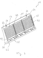
- the Fig. 1 and 2 show a soundproofing device, generally designated 10, on a track system 12.
- the track system 12 comprises, as a rail support arrangement 14, a plurality of sleepers 16 arranged in succession in a longitudinal direction of the track system. Rails 18 of the track system 12 are carried on the sleepers 16.
- a soundproofing element 11, which essentially provides the soundproofing device 10, is designed such that it can be fixed to the lateral end regions 20 of the sleepers 16, that is to say in principle to a lateral end region of the rail support arrangement 14.
- the soundproofing element 11 has a fastening region 22 positioned at the bottom in a height direction represented by a line H, that is to say, for example, in a direction orthogonal to the plane spanned by the rail support arrangement 14.
- a sound insulation area generally designated 24 and described in detail below.
- the fastening area 22 is constructed in such a way that it is adapted to the shape of the side end contour of the rail support arrangement 14, here the sleepers 16.
- the fastening region 22, adapted to the angular outer circumferential contour of the sleepers 16 forms a corresponding angular contour with a first fastening fitting region section 28 and a second fastening fitting region section 30 arranged at an angle thereto in a fastening fitting region generally denoted by 26.
- the first fastening fitting region section 28 has one on a top side 32 of the sleepers 16 fastening fitting area underside 34 to be positioned lying on.
- the second fastening fitting region section 30 has a fastening fitting region end 38 to be positioned against a lateral end face 36 of the sleepers 16.
- the fastening organ through openings 40 can be designed in the manner of an elongated hole.
- the fastening organ receiving openings to be provided in the rails 16 can be provided, for example, by dowel elements or the like that are already fitted into them during the production of concrete rails.
- it is also dimensioned such that it extends in the longitudinal direction of the track system over a plurality of sleepers and can therefore also be firmly connected to a plurality of sleepers.
- the soundproofing area 24 of the soundproofing device 10 or the soundproofing element 11 has a soundproofing side 42 to be positioned facing the rails 18 and a rear side 44 to be positioned facing away from the rails 18.
- the soundproofing area 24 is designed such that, starting from the fastening area 22, it extends in the direction away from the rails 18, that is to say inclined from the soundproofing side 42 to the rear side 44.
- this enables the fastening area 22 to be fastened to the sleepers 16, that is to say comparatively close to the rails 18, but on the other hand it ensures that the soundproofing device 10 does not intervene in the regular light space which is to be kept basically free.
- the soundproofing element 11 is formed on the soundproofing side 42 with a soundproofing formation generally designated 46.
- This soundproofing formation comprises a plurality of ones arranged one above the other and extending, for example, in a longitudinal direction of the track system or also in a longitudinal direction of a soundproofing device Soundproofing projections 48.
- the soundproofing projections 48 are arranged one above the other, the soundproofing projections 48 being arranged one above the other being offset due to the inclination of the sound insulation region 24 in the direction away from the rails 18, but lying overlapping one another.
- the soundproofing projections 48 have a generally triangular or sawtooth-like cross-sectional contour and have an upper sound reflecting surface 50 and a lower sound reflecting surface 52.
- the lower sound reflection surface 52 and the upper sound reflection surface 50 of two immediately adjacent sound insulation projections 48 delimit a sound insulation recess 56 ending in a recess apex region 54.
- the sound insulation projections 48 are basically designed in such a way that their lower sound reflection surfaces 52 are oriented such that sound emitted by a rail running surface 58 of an immediately adjacent rail 18 is reflected in a downward direction, that is to say in the direction of the rail support arrangement 14 or the sleepers 16.
- the contact area between a respective rail running surface 58 and the outer peripheral surface of a wheel forms an essential sound source.
- Recognizable orientation of the lower sound reflection surfaces 52 ensures that sound S emanating from this sound source is not reflected upwards into the environment, but downwards, where this sound is then efficiently attenuated, for example in the ballast bed, by multiple reflections or by absorption.
- the lower sound reflection surfaces 52 are arranged such that their inclination with respect to the height direction H from lower ones positioned further down Sound reflection surfaces 52 increases to lower sound reflection surfaces 52 positioned further up. It can be clearly seen that the angle of attack ⁇ 1 formed between an extension line L 1 of the bottom sound reflection surface 52 ′ positioned at the bottom and the height direction H is smaller than the angle of attack ⁇ 2 between the height direction H and the extension line L 2 of a lower position positioned further up Sound reflection surface 52 ". It goes without saying that not all of the lower sound reflection surfaces 52 need to have different angles of attack from one another. Of course, groups of lower sound reflection surfaces 42 can also be provided here, which are of the same height direction H.
- Fig. 1 One recognizes in Fig. 1 that several fields 59 lying next to one another in the longitudinal direction of the track system or also in the longitudinal direction of the soundproofing element with soundproofing projections 48 arranged one above the other are provided on the soundproofing element 11, each of which is separated or delimited by a separating web 60.
- This leads to an increased stability of the soundproofing element 11.
- This can be made of rubber material on the one hand for reasons of cost and on the other hand for reasons of stability.
- So-called tire cord or similar material can be used here, for example, in which textile fibers, PE fibers, polyester fibers, glass fibers or carbon fibers are embedded in the new rubber material, which have a length in the range of 15 mm to 30 mm, for example.
- This near-surface volume area of the soundproofing element 11 can have a thickness in the range from 0.5 cm to approximately 2 cm.
- the core area of the soundproofing element 11 can be constructed with bound rubber granulate, which can preferably be obtained by recycling used rubber, for example used tires, and can be bound by adhesive and / or vulcanization.
- a layer of not yet crosslinked, preferably fiber-reinforced new rubber material can first be inserted into a molded element.
- the construction material of the core area ie the granulate material
- a layer of new rubber material preferably fiber-reinforced.
- Another molded part is applied from above. The two molded parts are pressed against one another under pressure and temperature in order to trigger the crosslinking process in the new rubber material or to bind the granulate material to one another.
- a soundproofing element 11 produced in this way is comparatively stiff, in particular due to the stabilizing effect of the fiber-reinforced new rubber material, and does not lose its stability even under prolonged exposure to the weather. Also, due to the construction material described above, the soundproofing element 11 is so stable in its fastening area 22 that a stable mounting on the rail support arrangement 14 can be ensured using the fastening members, which are designed, for example, as screw bolts.
- FIGS 3 to 5 An alternative embodiment of the soundproofing device 10 is shown in FIGS 3 to 5 shown.
- the structure of this type of configuration essentially corresponds to that described above.
- the soundproofing projections 48 are arranged at a smaller mutual distance, which means that the upper soundproofing surfaces 50 and lower soundproofing surfaces 52, which each delimit a soundproofing recess 56, form an acute angle between them.
- This also makes it more efficient Soundproofing mechanism provided.
- two mounting eyelets 64 can be provided on an upwardly oriented upper side 62 of the sound insulation element 11 in order to be able to lift the soundproofing device 10 from a truck, for example, and to position it on the rail support arrangement 14. This enables the construction of the soundproofing device 10 or the respective soundproofing elements 11 with a comparatively large length of 1.5 m and more, so that the soundproofing element 11 can extend over several thresholds and can be connected to them. After attachment to the rail support assembly 14, the mounting eyelets 64 can be removed so that they do not protrude into the standard light room.
- FIGS 6 to 10 Another modified embodiment of the soundproofing device 10 or the soundproofing element 11 is shown in FIGS 6 to 10 shown.
- the basic structure of the soundproofing element 11 corresponds, in particular also with regard to the design of the soundproofing formation 46 provided on the soundproofing side 42, to the structure described above, so that reference can be made to the relevant statements.
- a plurality of, preferably pyramid-shaped, sound insulation increases and / or sound insulation depressions 66 arranged in groups or rows can be provided.
- These sound insulation increases or / and sound insulation depressions 66 provided, for example, on the respective lower sound reflection surfaces 52 lead to an increased scattering of the sound occurring on the sound insulation side 42.
- Such increases in sound insulation or sound reduction 66 can of course also in the in the 1 to 5 Shown embodiments of the soundproofing element 11 may be provided.
- Soundproofing element 11 shown is provided, for example, in at least one, preferably each of the fields 59, a closing flap 68.
- This forms an integral part of the soundproofing element 11 and is therefore produced with it as one body.
- the end flap 68 adjoins the remaining part of the soundproofing element 11 in the region of a deformation hinge region 70.
- the deformation hinge region 70 is provided, for example, in the region of a groove-like depression 72 opposite a recess apex 54 on the rear 44.
- the end flap 68 is separated from the remaining part of the soundproofing element 11 by a generally U-shaped recess 74.
- a relief opening 76 which is also essentially delimited by the U-shaped recess 74.
- the closure flap 68 can be pivoted in the deformation hinge region 70 with respect to the remaining part of the soundproofing element 11, in particular it can be swung in the direction of the rear side 44 of the soundproofing element 11.
- the end flap 68 opens the relief opening 76 at least in some areas.
- the sound insulation formation 46 is also provided or continued in the region of the end flap / s 68 on the sound insulation side 42.
- a further improvement in the sound insulation behavior can be achieved by a sound insulation lip 70 seen in the area of the upper side 62 of the sound insulation element 11.
- the soundproofing lip 78 extends from the upper side 62 on the soundproofing side 42 or in the direction of the soundproofing side 42 and diagonally upwards away from the rear side 44.
- the reflection behavior provided in particular by the lower sound reflection surfaces 52 is also continued in the upper region or going beyond the upper side 62.
Landscapes
- Engineering & Computer Science (AREA)
- Architecture (AREA)
- Civil Engineering (AREA)
- Structural Engineering (AREA)
- Railway Tracks (AREA)
- Train Traffic Observation, Control, And Security (AREA)
- Platform Screen Doors And Railroad Systems (AREA)
- Machines For Laying And Maintaining Railways (AREA)
Priority Applications (4)
| Application Number | Priority Date | Filing Date | Title |
|---|---|---|---|
| PL16185430T PL3135813T3 (pl) | 2015-08-27 | 2016-08-24 | Urządzenie do izolacji akustycznej dla torowiska |
| SI201630685T SI3135813T1 (sl) | 2015-08-27 | 2016-08-24 | Protihrupna naprava za tirno napravo |
| RS20200600A RS60341B1 (sr) | 2015-08-27 | 2016-08-24 | Uređaj za zvučnu izolaciju šinskog sistema |
| HRP20200868TT HRP20200868T1 (hr) | 2015-08-27 | 2020-06-01 | Uređaj za zvučnu izolaciju tračnog sustava |
Applications Claiming Priority (1)
| Application Number | Priority Date | Filing Date | Title |
|---|---|---|---|
| DE102015114219.8A DE102015114219A1 (de) | 2015-08-27 | 2015-08-27 | Schallschutzvorrichtung für eine Gleisanlage |
Publications (2)
| Publication Number | Publication Date |
|---|---|
| EP3135813A1 EP3135813A1 (de) | 2017-03-01 |
| EP3135813B1 true EP3135813B1 (de) | 2020-03-04 |
Family
ID=56799335
Family Applications (1)
| Application Number | Title | Priority Date | Filing Date |
|---|---|---|---|
| EP16185430.2A Active EP3135813B1 (de) | 2015-08-27 | 2016-08-24 | Schallschutzvorrichtung für eine gleisanlage |
Country Status (11)
| Country | Link |
|---|---|
| EP (1) | EP3135813B1 (pl) |
| DE (1) | DE102015114219A1 (pl) |
| DK (1) | DK3135813T3 (pl) |
| ES (1) | ES2792868T3 (pl) |
| HR (1) | HRP20200868T1 (pl) |
| HU (1) | HUE049766T2 (pl) |
| LT (1) | LT3135813T (pl) |
| PL (1) | PL3135813T3 (pl) |
| PT (1) | PT3135813T (pl) |
| RS (1) | RS60341B1 (pl) |
| SI (1) | SI3135813T1 (pl) |
Families Citing this family (3)
| Publication number | Priority date | Publication date | Assignee | Title |
|---|---|---|---|---|
| DE102018007317A1 (de) * | 2018-09-17 | 2020-03-19 | Alp Gmbh | Vorrichtung zum Dämpfen von Schallgeräuschen und Absorbieren von Schwingungen einer Eisenbahnschiene |
| DE202021101120U1 (de) | 2021-03-05 | 2022-06-08 | KRAIBURG STRAIL GmbH & Co. KG | Schalldämmwandelement für eine Gleisanlage |
| DE202022102882U1 (de) | 2022-05-25 | 2022-07-26 | KRAIBURG STRAIL GmbH & Co. KG | Schalldämmwandelement für eine Gleisanlage |
Family Cites Families (6)
| Publication number | Priority date | Publication date | Assignee | Title |
|---|---|---|---|---|
| DE3544481A1 (de) * | 1984-12-27 | 1986-07-03 | Dr.-Ing. Werner Weber Ingenieur-Gesellschaft mbH, 7530 Pforzheim | Schallschutzwand und dafuer geeignetes wandelement |
| ITTO20020303A1 (it) * | 2002-04-08 | 2003-10-08 | Fasano Eleonora | Barriera per abbattimento acustico dei rumori generati al piano del ferro per mezzi ferroviari e metropolitani in genere. |
| DE202006014248U1 (de) * | 2006-09-18 | 2008-02-07 | Manfred Jacob Kunststofftechnik Gmbh | Schallschutzwand |
| DE102009005439A1 (de) | 2009-01-21 | 2010-07-22 | Edilon) (Sedra Gmbh | Minischutzwand für Schwellengleise |
| KR20100137232A (ko) * | 2009-06-22 | 2010-12-30 | (주)엔텍엔지니어링 | 레일에 설치되는 방음장치 |
| FI122884B (fi) * | 2010-07-26 | 2012-08-15 | Jarmo Airaksinen | Yläpäästään vapaa seinärakenne ja seinärakenteen käyttö melu- tai näköesteenä |
-
2015
- 2015-08-27 DE DE102015114219.8A patent/DE102015114219A1/de not_active Withdrawn
-
2016
- 2016-08-24 EP EP16185430.2A patent/EP3135813B1/de active Active
- 2016-08-24 SI SI201630685T patent/SI3135813T1/sl unknown
- 2016-08-24 PT PT161854302T patent/PT3135813T/pt unknown
- 2016-08-24 DK DK16185430.2T patent/DK3135813T3/da active
- 2016-08-24 RS RS20200600A patent/RS60341B1/sr unknown
- 2016-08-24 PL PL16185430T patent/PL3135813T3/pl unknown
- 2016-08-24 ES ES16185430T patent/ES2792868T3/es active Active
- 2016-08-24 HU HUE16185430A patent/HUE049766T2/hu unknown
- 2016-08-24 LT LTEP16185430.2T patent/LT3135813T/lt unknown
-
2020
- 2020-06-01 HR HRP20200868TT patent/HRP20200868T1/hr unknown
Non-Patent Citations (1)
| Title |
|---|
| None * |
Also Published As
| Publication number | Publication date |
|---|---|
| ES2792868T3 (es) | 2020-11-12 |
| DK3135813T3 (da) | 2020-06-02 |
| SI3135813T1 (sl) | 2020-07-31 |
| RS60341B1 (sr) | 2020-07-31 |
| HRP20200868T1 (hr) | 2020-09-04 |
| PT3135813T (pt) | 2020-05-19 |
| HUE049766T2 (hu) | 2020-10-28 |
| EP3135813A1 (de) | 2017-03-01 |
| DE102015114219A1 (de) | 2017-03-02 |
| LT3135813T (lt) | 2020-04-10 |
| PL3135813T3 (pl) | 2020-08-24 |
Similar Documents
| Publication | Publication Date | Title |
|---|---|---|
| EP1762660B1 (de) | Verkehrs-Leit-Einrichtung | |
| WO2013010526A1 (de) | Schloss für eine fahrzeugtür mit federblech im einlaufbereich des schliessbolzens | |
| DE102019102226A1 (de) | Batterieträger mit deformierbarem Längsträger | |
| EP2210978A2 (de) | Minischutzwand für Schwellengleise | |
| DE212020000638U1 (de) | Kombinierte Vorrichtung zur Lärmminderung und Schalldämpfung für eine Schiene | |
| EP3135813A1 (de) | Schallschutzvorrichtung für eine gleisanlage | |
| DE102009037936A1 (de) | Rad für ein Schienenfahrzeug | |
| EP2683592B1 (de) | Kraftableitungskomponente für ein kraftfahrzeug zum schutz vor einem aufschlag einer bordsteinkante auf eine unterseite des kraftfahrzeugs | |
| DE202010000658U1 (de) | Schutzplankenanordnung | |
| DE102014217767A1 (de) | Schallschutzvorrichtung, insbesondere für eine Gleisanlage | |
| DE102014220703B4 (de) | Anordnung im Bereich eines Montageträgers im Vorderwagen eines Kraftfahrzeuges | |
| AT336664B (de) | Profilierte leitschiene | |
| DE102016119836A1 (de) | Leitplankenanordnung mit Ankerpfosten | |
| DE102007050650A1 (de) | Frontaufbau für ein Kraftfahrzeug | |
| DE202021101120U1 (de) | Schalldämmwandelement für eine Gleisanlage | |
| DE102014018066A1 (de) | Grundplatte, Schließvorrichtung und zugehöriges Kraftfahrzeug | |
| DE102012022471A1 (de) | Oberschiene für Sonnenschutzanlage | |
| EP3292245B1 (de) | Anordnung zur lagerung einer schienenfahrbahn und zugehörige schienenfahrbahn | |
| DE102018130419B4 (de) | Untere Stoßfängerabstützung für ein Kraftfahrzeug | |
| EP2284041A1 (de) | Tritthalterung | |
| DE102020113650B4 (de) | Schutzvorrichtung für einen Parkplatz für Kraftwagen | |
| EP2184213B1 (de) | Schienenfahrzeug mit einem Fahrzeugführerraum mit einer mindestens teilweise deformierbaren Fußbodenplatte | |
| EP2520719A2 (de) | Fahrzeugrückhaltesystem mit Anprallmatten | |
| EP1564334B1 (de) | Leiteinrichtung | |
| EP2521815B1 (de) | Begrünbares lärmschutzelement und lärmschutzwand |
Legal Events
| Date | Code | Title | Description |
|---|---|---|---|
| PUAI | Public reference made under article 153(3) epc to a published international application that has entered the european phase |
Free format text: ORIGINAL CODE: 0009012 |
|
| STAA | Information on the status of an ep patent application or granted ep patent |
Free format text: STATUS: THE APPLICATION HAS BEEN PUBLISHED |
|
| AK | Designated contracting states |
Kind code of ref document: A1 Designated state(s): AL AT BE BG CH CY CZ DE DK EE ES FI FR GB GR HR HU IE IS IT LI LT LU LV MC MK MT NL NO PL PT RO RS SE SI SK SM TR |
|
| AX | Request for extension of the european patent |
Extension state: BA ME |
|
| STAA | Information on the status of an ep patent application or granted ep patent |
Free format text: STATUS: REQUEST FOR EXAMINATION WAS MADE |
|
| 17P | Request for examination filed |
Effective date: 20170901 |
|
| RBV | Designated contracting states (corrected) |
Designated state(s): AL AT BE BG CH CY CZ DE DK EE ES FI FR GB GR HR HU IE IS IT LI LT LU LV MC MK MT NL NO PL PT RO RS SE SI SK SM TR |
|
| STAA | Information on the status of an ep patent application or granted ep patent |
Free format text: STATUS: EXAMINATION IS IN PROGRESS |
|
| 17Q | First examination report despatched |
Effective date: 20190117 |
|
| GRAP | Despatch of communication of intention to grant a patent |
Free format text: ORIGINAL CODE: EPIDOSNIGR1 |
|
| STAA | Information on the status of an ep patent application or granted ep patent |
Free format text: STATUS: GRANT OF PATENT IS INTENDED |
|
| RIC1 | Information provided on ipc code assigned before grant |
Ipc: E01B 19/00 20060101AFI20190920BHEP Ipc: E01B 26/00 20060101ALI20190920BHEP Ipc: E01F 8/00 20060101ALN20190920BHEP |
|
| INTG | Intention to grant announced |
Effective date: 20191016 |
|
| GRAS | Grant fee paid |
Free format text: ORIGINAL CODE: EPIDOSNIGR3 |
|
| GRAA | (expected) grant |
Free format text: ORIGINAL CODE: 0009210 |
|
| STAA | Information on the status of an ep patent application or granted ep patent |
Free format text: STATUS: THE PATENT HAS BEEN GRANTED |
|
| RIN1 | Information on inventor provided before grant (corrected) |
Inventor name: WEISS, WOLFGANG Inventor name: BARTOLOMAE, JOHANNES Inventor name: MOERTL, ANDREAS Inventor name: TUTZER, ROLAND Inventor name: MOELTER, TRISTAN Inventor name: NEUDECK, MICHAEL |
|
| AK | Designated contracting states |
Kind code of ref document: B1 Designated state(s): AL AT BE BG CH CY CZ DE DK EE ES FI FR GB GR HR HU IE IS IT LI LT LU LV MC MK MT NL NO PL PT RO RS SE SI SK SM TR |
|
| REG | Reference to a national code |
Ref country code: GB Ref legal event code: FG4D Free format text: NOT ENGLISH |
|
| REG | Reference to a national code |
Ref country code: CH Ref legal event code: NV Representative=s name: E. BLUM AND CO. AG PATENT- UND MARKENANWAELTE , CH Ref country code: CH Ref legal event code: EP |
|
| REG | Reference to a national code |
Ref country code: AT Ref legal event code: REF Ref document number: 1240480 Country of ref document: AT Kind code of ref document: T Effective date: 20200315 |
|
| REG | Reference to a national code |
Ref country code: DE Ref legal event code: R096 Ref document number: 502016009000 Country of ref document: DE |
|
| REG | Reference to a national code |
Ref country code: IE Ref legal event code: FG4D Free format text: LANGUAGE OF EP DOCUMENT: GERMAN |
|
| REG | Reference to a national code |
Ref country code: RO Ref legal event code: EPE |
|
| REG | Reference to a national code |
Ref country code: SE Ref legal event code: TRGR |
|
| REG | Reference to a national code |
Ref country code: PT Ref legal event code: SC4A Ref document number: 3135813 Country of ref document: PT Date of ref document: 20200519 Kind code of ref document: T Free format text: AVAILABILITY OF NATIONAL TRANSLATION Effective date: 20200511 |
|
| REG | Reference to a national code |
Ref country code: FI Ref legal event code: FGE |
|
| REG | Reference to a national code |
Ref country code: NL Ref legal event code: FP |
|
| REG | Reference to a national code |
Ref country code: HR Ref legal event code: TUEP Ref document number: P20200868T Country of ref document: HR |
|
| REG | Reference to a national code |
Ref country code: DK Ref legal event code: T3 Effective date: 20200528 |
|
| REG | Reference to a national code |
Ref country code: EE Ref legal event code: FG4A Ref document number: E018991 Country of ref document: EE Effective date: 20200331 |
|
| REG | Reference to a national code |
Ref country code: SK Ref legal event code: T3 Ref document number: E 34044 Country of ref document: SK |
|
| REG | Reference to a national code |
Ref country code: NO Ref legal event code: T2 Effective date: 20200304 |
|
| PG25 | Lapsed in a contracting state [announced via postgrant information from national office to epo] |
Ref country code: GR Free format text: LAPSE BECAUSE OF FAILURE TO SUBMIT A TRANSLATION OF THE DESCRIPTION OR TO PAY THE FEE WITHIN THE PRESCRIBED TIME-LIMIT Effective date: 20200605 |
|
| REG | Reference to a national code |
Ref country code: HR Ref legal event code: T1PR Ref document number: P20200868 Country of ref document: HR |
|
| REG | Reference to a national code |
Ref country code: HR Ref legal event code: ODRP Ref document number: P20200868 Country of ref document: HR Payment date: 20200817 Year of fee payment: 5 |
|
| REG | Reference to a national code |
Ref country code: HU Ref legal event code: AG4A Ref document number: E049766 Country of ref document: HU |
|
| PG25 | Lapsed in a contracting state [announced via postgrant information from national office to epo] |
Ref country code: SM Free format text: LAPSE BECAUSE OF FAILURE TO SUBMIT A TRANSLATION OF THE DESCRIPTION OR TO PAY THE FEE WITHIN THE PRESCRIBED TIME-LIMIT Effective date: 20200304 Ref country code: IS Free format text: LAPSE BECAUSE OF FAILURE TO SUBMIT A TRANSLATION OF THE DESCRIPTION OR TO PAY THE FEE WITHIN THE PRESCRIBED TIME-LIMIT Effective date: 20200704 |
|
| REG | Reference to a national code |
Ref country code: ES Ref legal event code: FG2A Ref document number: 2792868 Country of ref document: ES Kind code of ref document: T3 Effective date: 20201112 |
|
| REG | Reference to a national code |
Ref country code: DE Ref legal event code: R097 Ref document number: 502016009000 Country of ref document: DE |
|
| PLBE | No opposition filed within time limit |
Free format text: ORIGINAL CODE: 0009261 |
|
| STAA | Information on the status of an ep patent application or granted ep patent |
Free format text: STATUS: NO OPPOSITION FILED WITHIN TIME LIMIT |
|
| 26N | No opposition filed |
Effective date: 20201207 |
|
| PG25 | Lapsed in a contracting state [announced via postgrant information from national office to epo] |
Ref country code: MC Free format text: LAPSE BECAUSE OF FAILURE TO SUBMIT A TRANSLATION OF THE DESCRIPTION OR TO PAY THE FEE WITHIN THE PRESCRIBED TIME-LIMIT Effective date: 20200304 |
|
| REG | Reference to a national code |
Ref country code: HR Ref legal event code: ODRP Ref document number: P20200868 Country of ref document: HR Payment date: 20210817 Year of fee payment: 6 |
|
| PGFP | Annual fee paid to national office [announced via postgrant information from national office to epo] |
Ref country code: BG Payment date: 20210820 Year of fee payment: 6 Ref country code: FR Payment date: 20210819 Year of fee payment: 6 Ref country code: IE Payment date: 20210819 Year of fee payment: 6 |
|
| PGFP | Annual fee paid to national office [announced via postgrant information from national office to epo] |
Ref country code: PT Payment date: 20210812 Year of fee payment: 6 |
|
| PG25 | Lapsed in a contracting state [announced via postgrant information from national office to epo] |
Ref country code: MT Free format text: LAPSE BECAUSE OF FAILURE TO SUBMIT A TRANSLATION OF THE DESCRIPTION OR TO PAY THE FEE WITHIN THE PRESCRIBED TIME-LIMIT Effective date: 20200304 Ref country code: CY Free format text: LAPSE BECAUSE OF FAILURE TO SUBMIT A TRANSLATION OF THE DESCRIPTION OR TO PAY THE FEE WITHIN THE PRESCRIBED TIME-LIMIT Effective date: 20200304 |
|
| PG25 | Lapsed in a contracting state [announced via postgrant information from national office to epo] |
Ref country code: MK Free format text: LAPSE BECAUSE OF FAILURE TO SUBMIT A TRANSLATION OF THE DESCRIPTION OR TO PAY THE FEE WITHIN THE PRESCRIBED TIME-LIMIT Effective date: 20200304 Ref country code: AL Free format text: LAPSE BECAUSE OF FAILURE TO SUBMIT A TRANSLATION OF THE DESCRIPTION OR TO PAY THE FEE WITHIN THE PRESCRIBED TIME-LIMIT Effective date: 20200304 |
|
| REG | Reference to a national code |
Ref country code: HR Ref legal event code: ODRP Ref document number: P20200868 Country of ref document: HR Payment date: 20220817 Year of fee payment: 7 |
|
| PGFP | Annual fee paid to national office [announced via postgrant information from national office to epo] |
Ref country code: SK Payment date: 20220823 Year of fee payment: 7 Ref country code: RO Payment date: 20220812 Year of fee payment: 7 Ref country code: NO Payment date: 20220824 Year of fee payment: 7 Ref country code: LU Payment date: 20220823 Year of fee payment: 7 Ref country code: LT Payment date: 20220728 Year of fee payment: 7 Ref country code: EE Payment date: 20220823 Year of fee payment: 7 |
|
| PGFP | Annual fee paid to national office [announced via postgrant information from national office to epo] |
Ref country code: SI Payment date: 20220816 Year of fee payment: 7 Ref country code: RS Payment date: 20220811 Year of fee payment: 7 Ref country code: PL Payment date: 20220811 Year of fee payment: 7 Ref country code: LV Payment date: 20220819 Year of fee payment: 7 Ref country code: BE Payment date: 20220817 Year of fee payment: 7 |
|
| PG25 | Lapsed in a contracting state [announced via postgrant information from national office to epo] |
Ref country code: PT Free format text: LAPSE BECAUSE OF NON-PAYMENT OF DUE FEES Effective date: 20230224 |
|
| PG25 | Lapsed in a contracting state [announced via postgrant information from national office to epo] |
Ref country code: IE Free format text: LAPSE BECAUSE OF NON-PAYMENT OF DUE FEES Effective date: 20220824 Ref country code: FR Free format text: LAPSE BECAUSE OF NON-PAYMENT OF DUE FEES Effective date: 20220831 |
|
| REG | Reference to a national code |
Ref country code: HR Ref legal event code: ODRP Ref document number: P20200868 Country of ref document: HR Payment date: 20230817 Year of fee payment: 8 |
|
| PGFP | Annual fee paid to national office [announced via postgrant information from national office to epo] |
Ref country code: TR Payment date: 20230821 Year of fee payment: 8 |
|
| PGFP | Annual fee paid to national office [announced via postgrant information from national office to epo] |
Ref country code: HR Payment date: 20230817 Year of fee payment: 8 |
|
| REG | Reference to a national code |
Ref country code: EE Ref legal event code: MM4A Ref document number: E018991 Country of ref document: EE Effective date: 20230831 |
|
| REG | Reference to a national code |
Ref country code: LT Ref legal event code: MM4D Effective date: 20230824 |
|
| REG | Reference to a national code |
Ref country code: SK Ref legal event code: MM4A Ref document number: E 34044 Country of ref document: SK Effective date: 20230824 |
|
| PG25 | Lapsed in a contracting state [announced via postgrant information from national office to epo] |
Ref country code: LT Free format text: LAPSE BECAUSE OF NON-PAYMENT OF DUE FEES Effective date: 20230824 |
|
| PG25 | Lapsed in a contracting state [announced via postgrant information from national office to epo] |
Ref country code: LU Free format text: LAPSE BECAUSE OF NON-PAYMENT OF DUE FEES Effective date: 20230824 |
|
| PG25 | Lapsed in a contracting state [announced via postgrant information from national office to epo] |
Ref country code: RO Free format text: LAPSE BECAUSE OF NON-PAYMENT OF DUE FEES Effective date: 20230824 Ref country code: LU Free format text: LAPSE BECAUSE OF NON-PAYMENT OF DUE FEES Effective date: 20230824 Ref country code: LT Free format text: LAPSE BECAUSE OF NON-PAYMENT OF DUE FEES Effective date: 20230824 Ref country code: EE Free format text: LAPSE BECAUSE OF NON-PAYMENT OF DUE FEES Effective date: 20230831 Ref country code: SK Free format text: LAPSE BECAUSE OF NON-PAYMENT OF DUE FEES Effective date: 20230824 |
|
| PG25 | Lapsed in a contracting state [announced via postgrant information from national office to epo] |
Ref country code: SI Free format text: LAPSE BECAUSE OF NON-PAYMENT OF DUE FEES Effective date: 20230825 |
|
| REG | Reference to a national code |
Ref country code: BE Ref legal event code: MM Effective date: 20230831 |
|
| PG25 | Lapsed in a contracting state [announced via postgrant information from national office to epo] |
Ref country code: SI Free format text: LAPSE BECAUSE OF NON-PAYMENT OF DUE FEES Effective date: 20230825 Ref country code: RS Free format text: LAPSE BECAUSE OF NON-PAYMENT OF DUE FEES Effective date: 20230824 Ref country code: NO Free format text: LAPSE BECAUSE OF NON-PAYMENT OF DUE FEES Effective date: 20230831 Ref country code: LV Free format text: LAPSE BECAUSE OF NON-PAYMENT OF DUE FEES Effective date: 20230824 |
|
| PG25 | Lapsed in a contracting state [announced via postgrant information from national office to epo] |
Ref country code: BG Free format text: LAPSE BECAUSE OF NON-PAYMENT OF DUE FEES Effective date: 20220824 |
|
| PG25 | Lapsed in a contracting state [announced via postgrant information from national office to epo] |
Ref country code: BE Free format text: LAPSE BECAUSE OF NON-PAYMENT OF DUE FEES Effective date: 20230831 |
|
| REG | Reference to a national code |
Ref country code: SI Ref legal event code: KO00 Effective date: 20240429 |
|
| REG | Reference to a national code |
Ref country code: HR Ref legal event code: PBON Ref document number: P20200868 Country of ref document: HR Effective date: 20240824 |
|
| PG25 | Lapsed in a contracting state [announced via postgrant information from national office to epo] |
Ref country code: HR Free format text: LAPSE BECAUSE OF NON-PAYMENT OF DUE FEES Effective date: 20240824 |
|
| PG25 | Lapsed in a contracting state [announced via postgrant information from national office to epo] |
Ref country code: PL Free format text: LAPSE BECAUSE OF NON-PAYMENT OF DUE FEES Effective date: 20230824 |
|
| PGFP | Annual fee paid to national office [announced via postgrant information from national office to epo] |
Ref country code: NL Payment date: 20250821 Year of fee payment: 10 |
|
| PGFP | Annual fee paid to national office [announced via postgrant information from national office to epo] |
Ref country code: HU Payment date: 20250825 Year of fee payment: 10 |
|
| PGFP | Annual fee paid to national office [announced via postgrant information from national office to epo] |
Ref country code: FI Payment date: 20250822 Year of fee payment: 10 Ref country code: ES Payment date: 20250926 Year of fee payment: 10 |
|
| PGFP | Annual fee paid to national office [announced via postgrant information from national office to epo] |
Ref country code: DK Payment date: 20250825 Year of fee payment: 10 Ref country code: DE Payment date: 20250820 Year of fee payment: 10 |
|
| PGFP | Annual fee paid to national office [announced via postgrant information from national office to epo] |
Ref country code: IT Payment date: 20250825 Year of fee payment: 10 |
|
| PGFP | Annual fee paid to national office [announced via postgrant information from national office to epo] |
Ref country code: GB Payment date: 20250820 Year of fee payment: 10 |
|
| PGFP | Annual fee paid to national office [announced via postgrant information from national office to epo] |
Ref country code: AT Payment date: 20250821 Year of fee payment: 10 |
|
| PGFP | Annual fee paid to national office [announced via postgrant information from national office to epo] |
Ref country code: CH Payment date: 20250901 Year of fee payment: 10 Ref country code: SE Payment date: 20250820 Year of fee payment: 10 |
|
| PGFP | Annual fee paid to national office [announced via postgrant information from national office to epo] |
Ref country code: CZ Payment date: 20250818 Year of fee payment: 10 |