EP3135569B2 - Method for operating an auxiliary drive for a trailer, and system for driving at least one wheel of such a trailer - Google Patents
Method for operating an auxiliary drive for a trailer, and system for driving at least one wheel of such a trailer Download PDFInfo
- Publication number
- EP3135569B2 EP3135569B2 EP16183954.3A EP16183954A EP3135569B2 EP 3135569 B2 EP3135569 B2 EP 3135569B2 EP 16183954 A EP16183954 A EP 16183954A EP 3135569 B2 EP3135569 B2 EP 3135569B2
- Authority
- EP
- European Patent Office
- Prior art keywords
- trailer
- operating element
- user
- function
- auxiliary drive
- Prior art date
- Legal status (The legal status is an assumption and is not a legal conclusion. Google has not performed a legal analysis and makes no representation as to the accuracy of the status listed.)
- Active
Links
- 238000000034 method Methods 0.000 title claims description 24
- 238000004891 communication Methods 0.000 claims description 28
- 230000006854 communication Effects 0.000 claims description 28
- 230000003213 activating effect Effects 0.000 description 10
- 230000000694 effects Effects 0.000 description 10
- 230000004913 activation Effects 0.000 description 5
- 238000005516 engineering process Methods 0.000 description 3
- 241000282414 Homo sapiens Species 0.000 description 2
- 238000013459 approach Methods 0.000 description 2
- 230000007175 bidirectional communication Effects 0.000 description 2
- 230000003993 interaction Effects 0.000 description 2
- 238000010295 mobile communication Methods 0.000 description 2
- 230000008569 process Effects 0.000 description 2
- 239000003086 colorant Substances 0.000 description 1
- 238000012790 confirmation Methods 0.000 description 1
- 238000011161 development Methods 0.000 description 1
- 230000018109 developmental process Effects 0.000 description 1
- 238000013021 overheating Methods 0.000 description 1
- 238000013519 translation Methods 0.000 description 1
- 230000001960 triggered effect Effects 0.000 description 1
Images
Classifications
-
- B—PERFORMING OPERATIONS; TRANSPORTING
- B62—LAND VEHICLES FOR TRAVELLING OTHERWISE THAN ON RAILS
- B62D—MOTOR VEHICLES; TRAILERS
- B62D59/00—Trailers with driven ground wheels or the like
- B62D59/04—Trailers with driven ground wheels or the like driven from propulsion unit on trailer
Definitions
- the present invention relates to a method for operating an auxiliary drive for a trailer, in particular a caravan, a boat trailer, a sales van, a transport trailer or a car transport trailer, as well as a system for driving at least one wheel of such a trailer.
- auxiliary drives for trailers are already well known from the general state of the art.
- Such an auxiliary drive is used in particular to move the trailer in a state in which the trailer is uncoupled from a tractor. This is particularly advantageous for trailers that are moved, for example, on campsites or caravan parking lots and have to be maneuvered in the process.
- at least one drive element can be brought into interaction with at least one wheel of the trailer.
- the drive element is, for example, a drive roller of the auxiliary drive, wherein the drive roller is, for example, moved into contact with the wheel and kept in contact.
- the drive roller is driven with the aid of at least one motor, in particular an electric motor, of the auxiliary drive, whereby the wheel interacting with the drive roller is rotated or moved. This allows the trailer to be maneuvered precisely in the uncoupled state.
- the EN 20 2012 006 089 U1 discloses a shunting system for a trailer, with at least two shunting drives that can be arranged on the trailer, each with a drive roller, wherein each drive roller can be adjusted to a wheel of the trailer in order to drive it.
- a remote control unit for remote-controlled parking of a motor vehicle is known, with a housing and with elements for actuation.
- the EN 10 2012 007 986 A1 a maneuvering system for the automated maneuvering of a motor vehicle is known, with a vehicle-side control device which is designed to output control signals to a drive and/or steering device of the motor vehicle and thereby automatically carry out a maneuvering process of the motor vehicle.
- the EP 1 790 555 A1 an arrangement for manoeuvring a trailer with two wheels on each side. Furthermore, the EN 20 2012 006 089 U1 a shunting drive for a trailer is known. In addition, the US 2014/0338793 A1 a method of providing a computing device with wireless control of an operation of a control device.
- the object of the present invention is to provide a method and a system by means of which a trailer can be moved, in particular maneuvered, in a particularly simple and safe manner.
- a first aspect of the invention relates to a method for operating an auxiliary drive for a trailer, in particular a caravan, a boat trailer, a sales van, a transport trailer or a car transport trailer.
- at least one mobile terminal connected to the auxiliary drive via a wireless communication connection provides at least one functional control element by means of which at least one function of the auxiliary drive can be effected by a user or a person via the mobile terminal and the wireless connection.
- the mobile terminal provides at least one safety control element that is different from the functional control element, wherein the functional control element is enabled to effect the at least one function depending on at least one actuation or operation of the safety control element by the user.
- the functional control element basically serves to effect the at least one function of the auxiliary drive. To do this, the user operates or actuates the functional control element by, for example, touching and in particular pressing the functional control element.
- the at least one function is, for example, a drive function, in the context of which at least one wheel, i.e. a ground contact element of the trailer, is rotated and thus moved by means of the auxiliary drive. Since the trailer is supported on a roadway or ground via the wheel, for example, the trailer is driven or moved by driving or rotating the wheel and can thus be maneuvered, for example. In particular, the trailer can be maneuvered in its uncoupled state, in which the trailer is not coupled to a tractor.
- a drive function in the context of which at least one wheel, i.e. a ground contact element of the trailer, is rotated and thus moved by means of the auxiliary drive. Since the trailer is supported on a roadway or ground via the wheel, for example, the trailer is driven or moved by driving or rotating the wheel and can thus be maneuvered, for example. In particular, the trailer can be maneuvered in its uncoupled state, in which the trailer is not coupled to a tractor.
- the at least one function can be a so-called pivoting function, within the framework of which at least one drive element such as a drive roller of the auxiliary drive is moved in interaction and, for example, in contact with at least one wheel of the trailer.
- the auxiliary drive executes the at least one function when and preferably only when the functional control element is or is enabled for effecting the at least one function.
- the functional control element is enabled when the user operates or actuates the safety control element and, for example, touches and in particular presses it. This means, for example, that the functional control element is fundamentally or in an initial state or basic state blocked or deactivated with regard to the effecting of the at least one function. If the function control element is in this initial state or basic state and the user operates the function control element, function control element in the active state and the user operates the function control element while the function control element is in the initial state, the auxiliary drive does not carry out the at least one function. In other words, the auxiliary drive then does not carry out the at least one function.
- an active state of the functional control element is set or activated, for example.
- the functional control element is transferred to an active state.
- the at least one function is effected or the auxiliary drive carries out the at least one function.
- the auxiliary drive carries out the at least one function if and preferably only if the functional control element is in the active state, which in turn is effected by the safety control element being actuated. This enables particularly safe operation of the auxiliary drive as well as safe driving and thus maneuvering of the trailer, since, for example, unintentional and unwanted triggering of the at least one function can be avoided.
- the safety control element acts as a dead man's switch to ensure that both the functional control element and the safety control element must each be operated at least once in order to actually carry out at least one function.
- This makes it possible, for example, to distinguish between unwanted and unintentional operations of the functional control element by the user and intentional or intended operations, since in the case of unwanted or unintentional operations, for example, the user operates the functional control element but not the safety control element. In the case of intentional and desired operations, however, the user operates both the functional control element and the safety control element.
- the mobile device is, for example, a simple remote control, which, for example, only has the function of remotely controlling the auxiliary drive.
- the mobile device is, for example, a mobile communication device such as a cell phone or a smartphone, which is used to remotely control the auxiliary drive.
- a mobile communication device can also be used, for example, to make telephone calls.
- the mobile device is a tablet or a tablet PC, a laptop, a notebook or the like.
- the functional control element can be transferred from the basic state to the active state as a result of at least one actuation of the safety control element by the user and to be held in the active state for a period of time following the actuation of the safety control element or for a period of time following the termination of the actuation of the safety control element.
- This period of time is, for example, at least two seconds.
- the functional control element is in the active state - temporarily, namely during the predeterminable period of time - even when the safety control element is no longer being actuated by the user.
- the at least one function can therefore be effected by actuating the functional control element during the predeterminable period of time even when the safety control element is not being actuated by the user.
- the safety control element is provided as a control surface on a touch-sensitive screen of the mobile terminal.
- the configurations and advantages described for the functional control element designed as a control surface also apply to the safety control element designed as a control surface and vice versa. If the user touches the touch-sensitive screen in the area of the safety control element designed as a control surface, an actuation of the safety control element by the user can be reliably detected by means of the touch-sensitive screen. If the user no longer touches the touch-sensitive screen or if the distance between the user and the touch-sensitive screen exceeds the predeterminable threshold value, this detects that the actuation of the functional control element or the safety control element has ended. If the user stops activating the safety control element and/or the functional control element, the execution of at least one function is stopped.
- the invention provides that an actuation by the user of the released functional control element, i.e. one in the active state, is displayed by means of at least one symbol on a display of the mobile terminal. This visually communicates to the user that he is actually actuating the functional control element in order to actually effect the at least one function. Overall, it is thus possible to visually communicate the operation of the auxiliary drive to the user, so that particularly safe operation can be achieved.
- the invention also provides that the activation of the released functional control element by the user is displayed by means of the at least one symbol in an area of the mobile terminal that is different from the functional control element and the safety control element.
- the user can be reliably visually informed, even if the user covers the functional control element and the safety control element with his fingers, that he is activating both the safety control element and the functional control element and is thus actually activating the at least one function.
- the respective operations of the functional control element and the safety control element are recorded by the mobile device and in particular represent inputs into the mobile device.
- the function control element is released while the user is holding the safety control element operated, wherein the functional control element is blocked for executing the at least one function, while an actuation of the safety control element by the user does not take place.
- the functional control element is in the active state for as long as and only as long as the user operates the safety control element or an actuation of the control element by the user is detected.
- the user must therefore operate both the functional control element and the safety control element at the same time in order to actually execute the at least one function.
- the auxiliary drive carries out the at least one function if and preferably only if a simultaneous actuation of the safety control element and the functional control element by the user is detected by means of the mobile terminal.
- the user must therefore confirm the function control element and the safety control element simultaneously, for example using two fingers of one hand or using at least one finger of his first hand and at least one finger of his second hand, in order to actually carry out at least one function.
- This makes it possible to achieve particularly safe operation of the auxiliary drive, as the risk of the user's hands getting caught between moving components can be kept particularly low. In particular, this makes it possible to keep the risk of functions of the auxiliary drive being triggered inadvertently, for example when the user puts the mobile device in his pocket.
- the functional control element is blocked immediately after the user has finished activating the safety control element, i.e. it is switched or transferred to the basic state.
- the functional control element is switched from the active state to the basic state immediately, i.e. at least with almost no time delay and in particular without a specific time delay, when the user has finished activating the safety control element or when the user has detected that the safety control element has finished activating it. This enables particularly safe operation of the auxiliary drive.
- an actuation of the safety control element by the user is displayed by means of at least one symbol on the display of the mobile device.
- the at least one symbol is displayed on the display of the mobile device. This can visually communicate to the user that he is actually activating the safety control element. The user is thus visually communicated that the function control element is in the active state and the user can actually carry out the at least one function.
- the wireless communication connection is, for example, a radio connection or a wireless communication connection via radio technology.
- the wireless communication connection can be a connection via Bluetooth, WLAN (Wireless Local Area Network) or the like.
- the wireless communication connection means that the mobile device is not connected to the auxiliary drive via a physical line, but rather the The mobile terminal is connected to the auxiliary drive without such a physical cable, for example by means of radio technology, so that the mobile terminal can, for example, wirelessly exchange data with the auxiliary drive via the wireless communication connection.
- the functional control element and/or the safety control element can be designed, for example, as a mechanical control element, in particular as a button, wherein the mechanical control element can be moved, for example, relative to a housing of the mobile terminal between at least two different positions.
- the mechanical control element can be designed, in particular, as a button.
- the functional control element is provided as a control surface on a touch-sensitive screen of the mobile device.
- the touch-sensitive screen can be used, for example, to detect when the user approaches the mobile device and in particular the touch-sensitive screen. Such an approach is detected, for example, when a distance between the user and the touch-sensitive screen falls below a predeterminable threshold value, with the user, for example, touching the touch-sensitive screen.
- a distance between the user and the touch-sensitive screen in the area of the functional control element designed as a control surface falls below the predeterminable threshold value or if the user, for example, touches the touch-sensitive screen in the area of the functional control element designed as a control surface, an actuation of the functional control element by the user using the touch-sensitive screen is detected. This can ensure safe and simple operation of the auxiliary drive.
- a second aspect of the invention relates to a system for driving at least one wheel of a trailer, in particular a caravan, a boat trailer, a sales van, a transport trailer or a car transport trailer.
- the system comprises at least one auxiliary drive for driving the wheel.
- the system also comprises at least one mobile terminal that can be connected to the auxiliary drive via a wireless communication connection and has at least one functional control element by means of which at least one function of the auxiliary drive can be effected by a user via the mobile terminal and the wireless connection.
- the mobile terminal has at least one safety control element that is different from the functional control element, wherein the system is designed to release the functional control element depending on at least one actuation of the safety control element by the user for effecting the at least one function.
- the system is designed to carry out a method according to the invention.
- Advantages and embodiments of the first aspect of the invention are to be regarded as advantages and embodiments of the second aspect of the invention and vice versa.
- particularly safe operation of the auxiliary drive can be achieved by means of the system according to the invention, since the user does not only have to actuate the functional control element, but both the functional control element and the safety control element in order to actually effect the at least one function of the auxiliary drive.
- the safety control element is designed as a control surface on a touch-sensitive screen of the mobile terminal.
- the mobile terminal has a display with at least one display area that is different from the functional control element and the safety control element.
- an actuation of the enabled functional control element by the user can be displayed by means of at least one symbol on the display of the mobile terminal.
- the functional control element is designed as a control surface on a touch-sensitive screen of the mobile terminal. This makes it possible to achieve a particularly high level of functionality, since the area of the control surface can be used for different displays. Furthermore, this makes it possible to achieve particularly safe operation, since the actuation and termination of the actuation of the functional control element can be reliably detected.
- This display is, for example, the previously mentioned touch-sensitive screen, which is also commonly referred to as a touch display or touch screen.
- a further embodiment is characterized in that the at least one function is designed as a rotation function, by means of which a rotation of the trailer can be effected via the auxiliary drive, while a translational movement of the trailer is at least substantially avoided.
- the rotation function causes a rotation on the spot, so that the trailer rotates about its vertical axis or vertical direction, without essentially moving translationally, i.e. forwards or backwards.
- the trailer can be rotated in a particularly small space and aligned as required without the trailer colliding with other objects. This makes particularly safe operation possible.
- auxiliary drive drives the wheel in one direction of rotation during the turning function, while the auxiliary drive does not drive a second wheel of the trailer that is opposite the wheel in the transverse direction of the trailer.
- This has proven to be particularly advantageous for multi-axle trailers, which can then be turned in a particularly space-saving manner using the turning function.
- Such a multi-axle trailer has at least two axles that are arranged one after the other in the longitudinal direction of the vehicle, or one behind the other, with such an axle having at least two ground contact elements in the form of wheels that are arranged opposite one another in the transverse direction of the trailer.
- auxiliary drive during the rotation function, drives the wheel in a first direction of rotation and a second wheel, which is opposite the wheel in the transverse direction of the trailer, in a second direction of rotation opposite to the first direction of rotation.
- This has proven to be particularly advantageous for single-axle trailers, whereby such a single-axle trailer has exactly one axle.
- Such an axle comprises at least two ground contact elements in the form of wheels, which are arranged opposite one another in the transverse direction of the trailer and thus in the transverse direction of the vehicle and over which the trailer rolls onto the ground when driving.
- a further embodiment is characterized in that the function is designed as a maneuvering function, in which the auxiliary drive drives the wheel in one direction of rotation at a first speed and a second wheel opposite the wheel in the transverse direction of the trailer in the direction of rotation at a second speed that is different from the first speed and is greater than zero.
- the auxiliary drive drives the wheels in the same direction, but the first wheel is driven more strongly or at a higher speed than the second wheel, so that the trailer is moved forwards or backwards, but not along a straight line, but along a curve. This makes it particularly easy to maneuver the trailer.
- the second speed is at least one tenth and at most three eighths of the first speed.
- the auxiliary drive has at least one further function, which is designed as a drive function, in which the auxiliary drive drives the trailer along a straight line by driving the wheels, i.e. the first wheel and the second wheel, at a third speed that corresponds to 100%.
- the trailer is thus moved backwards or forwards and at least essentially along a straight line.
- the trailer does not corner as a result of the auxiliary drive.
- the shunting function provides that the first speed is in a range of 80% to 100% of the third speed and the second speed is in a range of 10% to 30% of the third speed. This allows the trailer to corner particularly advantageously as part of the shunting function.
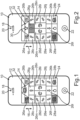
- Fig.1 shows a schematic plan view of a mobile terminal, designated as a whole by 10, which is designed as a mobile telecommunications terminal in the present case.
- the mobile terminal 10 is designed as a smartphone and is therefore designed to establish a telephone connection via radio technology.
- the mobile terminal 10 comprises a housing 12 and a display 14, which is designed as a touch-sensitive screen.
- the mobile terminal 10 has a Fig.1 by a double arrow 16, wherein at least one loudspeaker 18 for reproducing sounds is arranged above the display 14 in relation to this vertical direction.
- a camera 20 for capturing images is arranged above the loudspeaker 18 in the vertical direction of the mobile terminal 10. This means that the mobile terminal 10 has the loudspeaker 18 and the camera 20.
- an operating element 22 of the mobile terminal 10 is arranged under the display 14.
- the operating element 22 is designed as a mechanical operating element, whereby the operating element 22 is designed as a button in the present case.
- the operating element 22 can be switched between a Fig. 1 and 2 shown starting position and at least one operating position different from the starting position.
- at least one spring element supported at least indirectly on the operating element 22 is tensioned, so that the spring element provides a spring force which acts on the operating element 22 in the operating position.
- a user and thus, a person of the mobile terminal 10 can move the operating element 22 from the starting position to the operating position, whereby the spring element is tensioned.
- the user applies a force to the operating element 22, whereby the user presses the operating element 22, for example. If the user lets go of the operating element 22, the spring element can relax again so that the operating element 22 is moved from the operating position back to the starting position by means of the spring force. By moving the operating element 22 from the starting position to the operating position in this way, the user can operate the mobile terminal 10, whereby the movement of the operating element 22 is also referred to as actuating or operating.
- the mobile terminal 10 is used to carry out a method for operating an auxiliary drive for a trailer, in particular a caravan, a boat trailer, a sales van, a transport trailer or a car transport trailer.
- the auxiliary drive is, for example, at least indirectly held on a frame of the trailer and has, for example, a drive unit with at least two motors, in particular electric motors.
- the auxiliary drive has at least one drive element, in particular in the form of a drive roller.
- the trailer has at least one axle, which comprises two ground contact elements in the form of wheels arranged opposite one another in the transverse direction or transverse direction of the vehicle of the trailer.
- the wheels are held at least indirectly on the frame of the trailer and can be rotated relative to the frame, so that the trailer can roll on a floor or on a roadway via the wheels.
- a drive unit of the auxiliary drive is assigned to each wheel of the axle.
- the drive roller can be moved in translation between at least one use position and at least one non-use position, for example by means of a first of the motors in the longitudinal direction or vehicle longitudinal direction of the trailer.
- the drive roller In the use position, the drive roller is in contact or support with the associated wheel, wherein the drive roller is held in contact with the associated wheel and pressed against the wheel, for example by means of the first motor.
- the second motor serves, for example, to drive the drive roller. If the drive roller is in the use position and the drive roller is driven by the second motor, the wheel associated with the drive roller is driven, i.e. rotated relative to the frame, whereby the trailer is driven or moved. This makes it possible to move the trailer and in particular to maneuver it when the trailer is not coupled to a tractor.
- Such a state, in which the trailer is not coupled to a tractor is also referred to as an uncoupled state.
- the drive roller In the non-use position, the drive roller is spaced from the associated wheel so that the drive roller does not interact with the wheel. If the drive roller were to be driven by the second motor in the non-use position, the associated wheel would not be driven because the drive roller does not interact with the associated wheel.
- the mobile terminal 10 provides a graphical user interface 24 (GUI) by means of which the aforementioned user can operate the auxiliary drive so that the user can move and thus maneuver the uncoupled trailer via the mobile terminal 10 and the auxiliary drive.
- GUI graphical user interface 24
- the mobile terminal 10 is connected to the auxiliary drive via a wireless communication connection.
- the mobile terminal 10 comprises a first communication module (not visible in the figures), wherein the auxiliary drive comprises a second communication module (not visible in the figures).
- the wireless communication connection between the auxiliary drive and the mobile terminal 10 is established via these communication modules, so that, for example, the mobile terminal can transmit data to the second communication module and thus to the auxiliary drive via the first communication module, wherein the auxiliary drive can receive the data transmitted by the mobile terminal 10 via the second communication module.
- the auxiliary drive can transmit data to the first communication module and thus to the mobile terminal 10 via the second communication module, wherein the mobile terminal 10 can receive the data transmitted by the auxiliary drive or the second communication module via the first communication module.
- the communication modules are designed both to send and to receive the respective data, bidirectional communication between the mobile terminal 10 and the auxiliary drive is possible, so that the mobile terminal 10 and the auxiliary drive can exchange data and thus information in both directions.
- a wireless communication connection is advantageous because the user can then walk around the trailer and thus observe the trailer particularly well while the user holds the mobile terminal 10 in his hands and, for example, while the user maneuvers the trailer via the auxiliary drive, the wireless communication connection and the mobile terminal 10.
- the mobile terminal 10 Since the mobile terminal 10 provides the graphical user interface 24 on or by means of the display 14, the mobile terminal 10 has the graphical user interface 24.
- the graphical user interface 24 comprises a plurality of functional control elements 26a-n, by means of which at least one function of the auxiliary drive can be effected by the user via the mobile terminal 10 and the wireless communication connection. In other words, respective, mutually different functions of the auxiliary drive can be effected with the help of the functional control elements 26a-n.
- the functional control elements 26a, b serve, for example, to swivel in and out the respective drive roller assigned to the respective wheel. Swiveling in means the movement of the respective drive roller from the non-use position to the use position, while swiveling out means the reverse movement of the drive roller from the use position to the non-use position.
- the other functional control elements 26c-n can be used to effect different movements or driving or maneuvering maneuvers of the trailer via the auxiliary drive.
- the functional control element 26g can be used, for example, to simply drive the trailer forwards without the trailer turning or cornering. Accordingly, the functional control element 26l can be used, for example, to simply drive the trailer backwards without it cornering.
- the functional control elements 26c-f and 26h-k are used to cause the trailer to curve forwards or backwards, whereby the trailer then, for example, drives around curves with different curve radii. Furthermore, the function control elements 26m, n serve to effect the respective rotation functions of the auxiliary drive and thus of the trailer.
- the respective functional control element 26a-n has at least one directional arrow, by means of which the respective driving maneuver, in particular the direction or direction of travel of the trailer during the respective driving maneuver, is illustrated.
- the directional arrows of the functional control elements 26c-f and 26h-k are curved differently in order to illustrate the previously mentioned different curve radii.
- the respective turning function is to be understood as a rotation on the spot. In other words, the respective turning function causes the trailer to rotate about its vertical direction via the auxiliary drive, while a translational movement of the trailer forwards or backwards is at least essentially avoided. This means that the trailer can be turned or rotated in a very tight space, for example. This is provided in particular for a single-axle trailer, whereby the trailer has exactly one axle.
- the user can carry out a maneuvering function as the respective driving maneuver, in which the auxiliary drive drives one of the wheels in one direction of rotation at a first speed and the other wheel opposite the one wheel in the transverse direction of the trailer in the direction of rotation at a second speed that is different from the first speed and is greater than zero.
- the auxiliary drive drives, for example, the wheel on the outside of the curve at the first speed and the wheel on the inside of the curve at the second speed, which is lower than the first speed and greater than zero.
- the second speed is preferably at least one tenth and at most three eighths of the second speed.
- the forward travel mentioned above is, for example, a drive function of the auxiliary drive.
- the auxiliary drive drives the trailer along a straight line by the auxiliary drive driving the wheels at a third speed that corresponds to 100%.
- the shunting function provides that the first speed is in a range of 80% to 100% of the third speed and the second speed is in a range of 10% to 30% of the third speed.
- the wheel on the outside of the curve is driven at 80% to 100% of the third speed, while the wheel on the inside of the curve is driven at 10% to 30% of the third speed.
- This shunting function is preferably provided for a single-axle trailer and a multi-axle trailer.
- the second time period is longer than the first and third time periods, whereby the first and third time periods are, for example, of equal length.
- the first time period and the third time period last at least 5 seconds, whereby the second time period preferably lasts at least 10 seconds.
- the mobile terminal 10 provides two safety control elements 28a, b that are different from one another and different from the functional control elements 26a-n, wherein the safety control elements 28a, b are also components of the GUI and are therefore displayed on the display 14 or by means of the latter.
- the functional control elements 26a-n and the safety control elements 28a, b are not mechanical control elements, but rather control surfaces or control fields that are provided or displayed on the touch-sensitive screen (display 14).
- the functional control elements 26a-n and the safety control elements 28a, b are respective sub-areas or sub-areas of the graphical user interface 24, wherein these sub-areas or sub-areas (functional control elements 26a-n and safety control elements 28a, b) are arranged next to one another and thus differ from one another in terms of their respective position on the display 14.
- the safety control elements 28a, b are arranged below the functional control elements 26a-n relative to the vertical direction of the mobile terminal 10 and in particular in the lateral edge areas of the display 14 or the graphical user interface 24.
- the functional control elements 26a-n can be released to effect the respective function depending on at least one actuation of the respective safety control element 28a, b by the user.
- the method provides for the respective functional control element 26a-n to be released to effect the respective function depending on at least one actuation of the safety control element 28a, b by the user.
- the user In order to actually effect the respective function, i.e. the respective driving maneuver of the trailer using the auxiliary drive via the wireless communication connection and the mobile terminal 10, the user must not only actuate the respective corresponding functional control element 26a-n, but also at least one of the safety control elements 28a, b.
- the operation is carried out in such a way that the user touches the display 14 in the area of the respective functional control element 26a-n or in the area of the respective safety control element 28a, b. Such contact between the user and the display 14 is detected by means of the touch-sensitive screen.
- the respective safety control element 28a, b has a symbol in the form of a letter. This letter is a small "e".
- the safety control element 28a is actuated by the user, whereby the safety control element 28b is not actuated by the user, i.e. is unactuated or non-actuated.
- the symbol of the safety control element 28a, b has the same color as in the non-actuated state.
- the respective symbol of the respective safety control element 28a, b is backed by a colored area, whereby the area has a first color in the actuated state and a second color that is different from the first color in the non-actuated state.
- This colored area the color of which changes depending on the confirmation of the safety control element 28a, b, is thus a symbol by means of which the user is visually informed that the user is actuating the safety control element 28a, b or that such an actuation of the safety control element 28a, b by the user is detected.
- the respective direction arrow has a first color in the actuated state and a second color that is different from the first color in the non-confirmed state, and is backed by a colored area both in the actuated state and in the non-confirmed state, which has a first color in the confirmed state and a second color that is different from the first color in the non-actuated state.
- the functional control elements 26a-n are released so that the user can then actually carry out the respective driving maneuver by actuating one of the functional control elements 26a-n, i.e. by touching the display 14 in the area of the respective desired functional control element 26a-n.
- Fig.1 It is illustrated that the user actuates the function control element 26a or touches the display 14 in the area of the function control element 26a in order to pivot one of the drive rollers or both drive rollers.
- the method of the method provides that the respective functional control element 26a-n is released while the user keeps the respective safety control element 28a, b actuated, whereby the functional control elements 26a-n are blocked from executing the respective functions if the user does not actuate the safety control elements 28a, b.
- the functional control elements 26a-n are released immediately after a End of an operation of the safety control elements 28a, b by the user. This means that the function control elements 26a-n are only released while the user operates at least one of the safety control elements 28a, b. During all periods in which the user does not operate the safety control elements 28a, b, the function control elements 26a-n are blocked from executing the functions. In other words, if the user operates one of the function control elements 26a-n while the user does not operate any of the safety control elements 28a, b, the respective function is not executed or not carried out by the auxiliary drive.
- the user uses a finger of his first hand to operate the safety control element 28a, while he uses a finger of his second hand to operate the function control element 26a.
- Fig.2 it is illustrated that the user causes the trailer to move forward.
- the user actuates the functional control element 26g, while the user actuates and keeps actuated the safety control element 28a.
- both the actuation of the safety control element 28a by the user and the actuation of the released functional control element 26g by the user are displayed by means of at least one symbol on the display 14 by changing the color of the surface of the safety control element 28a and the colors of the surface and the direction arrow of the functional control element 26g compared to the non-actuated state.
- the activation of the enabled functional control element 26g by the user is displayed by means of at least one symbol 30 in an area 32 of the display 14 or the graphical user interface 24 that is different from the functional control elements 26a-n and the safety control elements 28a, b.
- the symbol 30 is a direction arrow that characterizes forward travel. The symbol 30 allows the user to recognize that the activation of the functional control element 26g and the safety control element 28a has been successful and that the respective function is actually being carried out by the auxiliary drive, even if he completely covers the functional control element 26g and the safety control element 28a with his respective fingers.
- At least one haptic feedback or a haptic effect is caused by actuating the safety control element 28a, b and/or the respective functional control element 26a-n.
- This haptic feedback occurs, for example, in that a vibration of the mobile terminal 10 is caused, in particular over a predeterminable period of time, by means of at least one vibration element of the mobile terminal 10 (not visible in the figures) when an actuation by the user of one of the safety control elements 28a, b and/or one of the particularly enabled functional control elements 26an is detected.
- This haptic feedback can also be used to haptically communicate to the user that an actuation by the user of the safety control element 28a or the corresponding functional control element 26a-n has occurred or is detected.
- the safety control element 28a or 28b functions as a dead man's switch, so to speak, which must be actuated by the user and kept actuated in order to release the functional control elements 26a-n and to actually be able to carry out the respective driving maneuver.
- This makes it possible to avoid unwanted and unintentional movements of the trailer as a result of unwanted and unintentional contact between the user and the display 14, for example when the user puts the mobile device 10 in his pocket.
- the auxiliary drive transmits data and thus information about its state, for example. For example, it is possible to display a fault, overheating of the auxiliary drive and/or other information about the auxiliary drive by means of the graphical user interface.
Landscapes
- Engineering & Computer Science (AREA)
- Chemical & Material Sciences (AREA)
- Combustion & Propulsion (AREA)
- Transportation (AREA)
- Mechanical Engineering (AREA)
- Handcart (AREA)
Description
Die vorliegende Erfindung betrifft ein Verfahren zum Betreiben eines Hilfsantriebs für einen Anhänger, insbesondere einen Wohnwagen, einen Bootsanhänger, einen Verkaufswagen, einen Transportanhänger oder einen Autotransportanhänger, sowie ein System zum Antreiben wenigstens eines Rads eines solchen Anhängers.The present invention relates to a method for operating an auxiliary drive for a trailer, in particular a caravan, a boat trailer, a sales van, a transport trailer or a car transport trailer, as well as a system for driving at least one wheel of such a trailer.
Hilfsantriebe für Anhänger, insbesondere für Wohnwagen, Bootsanhänger, Verkaufswagen, Transportanhänger und ähnliche Anhänger sind aus dem allgemeinen Stand der Technik bereits hinlänglich bekannt. Ein solcher Hilfsantrieb dient insbesondere dazu, den Anhänger in einem Zustand, in welchem der Anhänger von einer Zugmaschine abgekoppelt ist, zu bewegen. Dies ist besonders vorteilhaft bei Anhängern, die beispielsweise auf Campingplätzen oder Wohnwagen-Parkplätzen bewegt und dabei rangiert werden müssen. Bei einem solchen bekannten Hilfsantrieb ist wenigstens ein Antriebselement mit zumindest einem Rad des Anhängers in Zusammenwirken bringbar. Bei dem Antriebselement handelt es sich beispielsweise um einen Antriebswalze des Hilfsantriebs, wobei die Antriebswalze beispielsweise in Kontakt mit dem Rad bewegt und in Kontakt gehalten wird. Mithilfe wenigstens eines Motors, insbesondere eines Elektromotors, des Hilfsantriebs wird die Antriebswalze angetrieben, wodurch das sich in Zusammenwirken mit der Antriebswalze befindende Rad gedreht beziehungsweise bewegt wird. Dadurch kann der Anhänger in abgekoppeltem Zustand präzise rangiert werden.Auxiliary drives for trailers, in particular for caravans, boat trailers, sales vans, transport trailers and similar trailers are already well known from the general state of the art. Such an auxiliary drive is used in particular to move the trailer in a state in which the trailer is uncoupled from a tractor. This is particularly advantageous for trailers that are moved, for example, on campsites or caravan parking lots and have to be maneuvered in the process. In such a known auxiliary drive, at least one drive element can be brought into interaction with at least one wheel of the trailer. The drive element is, for example, a drive roller of the auxiliary drive, wherein the drive roller is, for example, moved into contact with the wheel and kept in contact. The drive roller is driven with the aid of at least one motor, in particular an electric motor, of the auxiliary drive, whereby the wheel interacting with the drive roller is rotated or moved. This allows the trailer to be maneuvered precisely in the uncoupled state.
Die
Aus der
Außerdem ist der
Außerdem offenbart die
Aufgabe der vorliegenden Erfindung ist es, ein Verfahren ein System zu schaffen, mittels welchen ein Anhänger auf besonders einfache und sichere Weise bewegt, insbesondere rangiert, werden kann.The object of the present invention is to provide a method and a system by means of which a trailer can be moved, in particular maneuvered, in a particularly simple and safe manner.
Diese Aufgabe wird erfindungsgemäß durch ein Verfahren mit den Merkmalen des Patentanspruchs 1 sowie durch ein System mit den Merkmalen des Patentanspruchs 6 gelöst. Vorteilhafte Ausgestaltungen mit zweckmäßigen Weiterbildungen der Erfindung sind in den übrigen Ansprüchen angegeben.This object is achieved according to the invention by a method having the features of patent claim 1 and by a system having the features of patent claim 6. Advantageous embodiments with expedient further developments of the invention are specified in the remaining claims.
Ein erster Aspekt der Erfindung betrifft ein Verfahren zum Betreiben eines Hilfsantriebs für einen Anhänger, insbesondere einen Wohnwagen, einen Bootsanhänger, einen Verkaufswagen, einen Transportanhänger oder einen Autotransportanhänger. Bei dem Verfahren stellt zumindest ein mit dem Hilfsantrieb über eine drahtlose Kommunikationsverbindung verbundenes mobiles Endgerät wenigstens ein Funktionsbedienelement bereit, mittels welchem wenigstens eine Funktion des Hilfsantriebs von einem Nutzer beziehungsweise einer Person über das mobile Endgerät und die drahtlose Verbindung bewirkbar ist.A first aspect of the invention relates to a method for operating an auxiliary drive for a trailer, in particular a caravan, a boat trailer, a sales van, a transport trailer or a car transport trailer. In the method, at least one mobile terminal connected to the auxiliary drive via a wireless communication connection provides at least one functional control element by means of which at least one function of the auxiliary drive can be effected by a user or a person via the mobile terminal and the wireless connection.
Ferner stellt das mobile Endgerät wenigstens ein von dem Funktionsbedienelement unterschiedliches Sicherheitsbedienelement bereit, wobei das Funktionsbedienelement in Abhängigkeit von wenigstens einer durch den Nutzer bewirkten Betätigung beziehungsweise Bedienung des Sicherheitsbedienelements für das Bewirken der wenigstens einen Funktion freigegeben wird. Mit anderen Worten dient das Funktionsbedienelement grundsätzlich dazu, die wenigstens eine Funktion des Hilfsantriebs zu bewirken. Hierzu bedient beziehungsweise betätigt der Nutzer das Funktionsbedienelement, indem der Nutzer das Funktionsbedienelement beispielsweise berührt und insbesondere drückt.Furthermore, the mobile terminal provides at least one safety control element that is different from the functional control element, wherein the functional control element is enabled to effect the at least one function depending on at least one actuation or operation of the safety control element by the user. In other words, the functional control element basically serves to effect the at least one function of the auxiliary drive. To do this, the user operates or actuates the functional control element by, for example, touching and in particular pressing the functional control element.
Bei der wenigstens einen Funktion handelt es sich beispielsweise um eine Antriebsfunktion, in deren Rahmen wenigstens ein Rad, das heißt ein Bodenkontaktelement des Anhängers mittels des Hilfsantriebs gedreht und somit bewegt wird. Da der Anhänger beispielsweise über das Rad auf einer Fahrbahn beziehungsweise einem Boden abgestützt ist, wird der Anhänger durch das Antreiben beziehungsweise Drehen des Rades angetrieben beziehungsweise bewegt und kann somit beispielsweise rangiert werden. Insbesondere kann der Anhänger dadurch in seinem abgekoppelten Zustand rangiert werden, in welchem der Anhänger nicht mit einer Zugmaschine gekoppelt ist.The at least one function is, for example, a drive function, in the context of which at least one wheel, i.e. a ground contact element of the trailer, is rotated and thus moved by means of the auxiliary drive. Since the trailer is supported on a roadway or ground via the wheel, for example, the trailer is driven or moved by driving or rotating the wheel and can thus be maneuvered, for example. In particular, the trailer can be maneuvered in its uncoupled state, in which the trailer is not coupled to a tractor.
Ferner kann es sich bei der wenigstens einen Funktion um eine sogenannte Einschwenkfunktion handeln, in deren Rahmen wenigstens ein Antriebselement wie beispielsweise eine Antriebswalze des Hilfsantriebs in Zusammenwirken und dabei beispielsweise in Kontakt mit wenigstens einem Rad des Anhängers bewegt wird.Furthermore, the at least one function can be a so-called pivoting function, within the framework of which at least one drive element such as a drive roller of the auxiliary drive is moved in interaction and, for example, in contact with at least one wheel of the trailer.
Im Rahmen des erfindungsgemäßen Verfahrens ist es nun vorgesehen, dass der Hilfsantrieb die wenigstens eine Funktion dann und vorzugsweise nur dann ausführt, wenn das Funktionsbedienelement für das Bewirken der wenigstens einen Funktion freigegeben wird beziehungsweise ist. Das Funktionsbedienelement wird dabei freigegeben, indem der Nutzer das Sicherheitsbedienelement bedient beziehungsweise betätigt und dabei beispielsweise berührt und insbesondere drückt. Dies bedeutet beispielsweise, dass das Funktionsbedienelement grundsätzlich beziehungsweise in einem Ausgangszustand oder Grundzustand hinsichtlich des Bewirkens der wenigstens einen Funktion gesperrt oder deaktiviert ist. Befindet sich das Funktionsbedienelement in diesem Ausgangszustand oder Grundzustand und betätigt der Nutzer das Funktionsbedienelement, Funktionsbedienelement in dem Aktivzustand und betätigt der Nutzer das Funktionsbedienelement, während sich das Funktionsbedienelement in dem Ausgangszustand befindet, so führt der Hilfsantrieb die wenigstens eine Funktion nicht aus. Mit anderen Worten unterbleibt dann ein Ausführen der wenigstens einen Funktion durch den Hilfsantrieb.Within the scope of the method according to the invention, it is now provided that the auxiliary drive executes the at least one function when and preferably only when the functional control element is or is enabled for effecting the at least one function. The functional control element is enabled when the user operates or actuates the safety control element and, for example, touches and in particular presses it. This means, for example, that the functional control element is fundamentally or in an initial state or basic state blocked or deactivated with regard to the effecting of the at least one function. If the function control element is in this initial state or basic state and the user operates the function control element, function control element in the active state and the user operates the function control element while the function control element is in the initial state, the auxiliary drive does not carry out the at least one function. In other words, the auxiliary drive then does not carry out the at least one function.
Betätigt der Nutzer das Sicherheitsbedienelement, so wird beispielsweise ein Aktivzustand des Funktionsbedienelements eingestellt beziehungsweise aktiviert. Mit anderen Worten wird das Funktionsbedienelement in einen Aktivzustand überführt. Befindet sich das Funktionsbedienelement in dem Aktivzustand und betätigt der Nutzer das Funktionsbedienelement, während sich das Funktionsbedienelement in dem Aktivzustand befindet, so wird die wenigstens eine Funktion bewirkt beziehungsweise der Hilfsantrieb führt die wenigstens eine Funktion aus. Dies bedeutet, dass der Hilfsantrieb die wenigstens eine Funktion dann und vorzugsweise nur dann ausführt, wenn sich das Funktionsbedienelement in dem Aktivzustand befindet, was wiederum dadurch bewirkt wird, dass das Sicherheitsbedienelement betätigt wird. Hierdurch können ein besonders sicherer Betrieb des Hilfsantriebs sowie ein sicheres Antreiben und somit Rangieren des Anhängers realisiert werden, da beispielsweise ein unbeabsichtigtes und ungewünschtes Auslösen der wenigstens einen Funktion vermieden werden kann.If the user operates the safety control element, an active state of the functional control element is set or activated, for example. In other words, the functional control element is transferred to an active state. If the functional control element is in the active state and the user operates the functional control element while the functional control element is in the active state, the at least one function is effected or the auxiliary drive carries out the at least one function. This means that the auxiliary drive carries out the at least one function if and preferably only if the functional control element is in the active state, which in turn is effected by the safety control element being actuated. This enables particularly safe operation of the auxiliary drive as well as safe driving and thus maneuvering of the trailer, since, for example, unintentional and unwanted triggering of the at least one function can be avoided.
Das Sicherheitsbedienelement fungiert dabei sozusagen als Totmannschalter um sicherzustellen, dass sowohl das Funktionsbedienelement als auch das Sicherheitsbedienelement jeweils wenigstens einmal betätigt werden müssen, um die wenigstens eine Funktion tatsächlich zu bewirken. Dadurch können beispielsweise ungewollt und unbeabsichtigt durch den Nutzer bewirkte Betätigungen des Funktionsbedienelements von gewollten beziehungsweise beabsichtigten Betätigungen unterschieden werden, da der Nutzer beispielsweise bei ungewollten beziehungsweise unbeabsichtigten Betätigungen das Funktionsbedienelement, nicht jedoch das Sicherheitsbedienelement betätigt. Bei beabsichtigten und gewünschten jedoch betätigt der Nutzer sowohl das Funktionsbedienelement als auch das Sicherheitsbedienelement. In der Folge ist es beispielsweise möglich, die Gefahr, dass es zu unerwünschten Ausführungen der wenigstens einen Funktion kommt, wenn der Nutzer das mobile Endgerät handhabt und dabei beispielsweise verstaut beziehungsweise in seine Tasche steckt, besonders gering zu halten.The safety control element acts as a dead man's switch to ensure that both the functional control element and the safety control element must each be operated at least once in order to actually carry out at least one function. This makes it possible, for example, to distinguish between unwanted and unintentional operations of the functional control element by the user and intentional or intended operations, since in the case of unwanted or unintentional operations, for example, the user operates the functional control element but not the safety control element. In the case of intentional and desired operations, however, the user operates both the functional control element and the safety control element. As a result, it is possible, for example, to keep the risk of unwanted execution of at least one function particularly low when the user handles the mobile device and, for example, stows it away or puts it in his pocket.
Das mobile Endgerät ist beispielsweise eine einfache Fernbedienung, welche beispielsweise lediglich die Funktion hat, den Hilfsantrieb fernzusteuern. Vorzugsweise handelt es sich bei dem mobilen Endgerät jedoch beispielsweise um ein mobiles Kommunikationsendgerät wie beispielsweise ein Handy oder ein Smartphone, welches zum Fernbedienen des Hilfsantriebs genutzt wird. Ein solches mobiles Kommunikationsendgerät kann beispielsweise ferner dazu genutzt werden, Telefongespräche zu führen. Ferner ist es denkbar, dass es sich bei dem mobilen Endgerät um ein Tablet beziehungsweise einen Tablet-PC, einen Laptop, ein Notebook oder dergleichen handelt.The mobile device is, for example, a simple remote control, which, for example, only has the function of remotely controlling the auxiliary drive. Preferably, however, the mobile device is, for example, a mobile communication device such as a cell phone or a smartphone, which is used to remotely control the auxiliary drive. Such a mobile communication device can also be used, for example, to make telephone calls. It is also conceivable that the mobile device is a tablet or a tablet PC, a laptop, a notebook or the like.
Es ist möglich, dass das Funktionsbedienelement infolge wenigstens einer durch den Nutzer bewirkten Betätigung des Sicherheitsbedienelements aus dem Grundzustand in den Aktivzustand überführt und während einer sich an die Betätigung des Sicherheitsbedienelements beziehungsweise während einer sich an ein Beenden der Betätigung des Sicherheitsbedienelements anschließenden Zeitdauer in dem Aktivzustand gehalten wird. Bei dieser Zeitdauer handelt es sich beispielsweise um wenigstens zwei Sekunden. Dies bedeutet, dass sich das Funktionsbedienelement - vorrübergehend, nämlich während der vorgebbaren Zeitdauer - auch dann in dem Aktivzustand befindet, wenn das Sicherheitsbedienelement nicht mehr durch den Nutzer betätigt wird. Somit kann die wenigstens eine Funktion durch Betätigen des Funktionsbedienelements während der vorgebbaren Zeitdauer auch dann bewirkt werden, wenn das Sicherheitsbedienelement nicht durch den Nutzer betätigt wird.It is possible for the functional control element to be transferred from the basic state to the active state as a result of at least one actuation of the safety control element by the user and to be held in the active state for a period of time following the actuation of the safety control element or for a period of time following the termination of the actuation of the safety control element. This period of time is, for example, at least two seconds. This means that the functional control element is in the active state - temporarily, namely during the predeterminable period of time - even when the safety control element is no longer being actuated by the user. The at least one function can therefore be effected by actuating the functional control element during the predeterminable period of time even when the safety control element is not being actuated by the user.
Erfindungsgemäß ist es vorgesehen, dass das Sicherheitsbedienelement als Bedienfläche auf einem berührungsempfindlichen Bildschirm des mobilen Endgeräts bereitgestellt wird. Dabei gelten die zu dem als Bedienfläche ausgebildeten Funktionsbedienelement geschilderten Ausgestaltungen und Vorteile auch für das als Bedienfläche ausgebildete Sicherheitsbedienelement und umgekehrt. Berührt somit der Nutzer den berührungsempfindlichen Bildschirm im Bereich des als Bedienfläche ausgebildeten Sicherheitsbedienelements, so kann eine durch den Nutzer bewirkte Betätigung des Sicherheitsbedienelements mittels des berührungsempfindlichen Bildschirms sicher erfasst werden. Berührt der Nutzer des berührungsempfindlichen Bildschirm nicht mehr beziehungsweise überschreitet der Abstand zwischen dem Nutzer und dem berührungsempfindlichen Bildschirm des vorgebbaren Schwellenwert, so wird dadurch ein Beenden der Betätigung des Funktionsbedienelements beziehungsweise des Sicherheitsbedienelements erfasst. Beendet somit der Nutzer die Betätigung des Sicherheitsbedienelements und/oder des Funktionsbedienelements, so wird das Ausführen der wenigstens einen Funktion gestoppt.According to the invention, it is provided that the safety control element is provided as a control surface on a touch-sensitive screen of the mobile terminal. The configurations and advantages described for the functional control element designed as a control surface also apply to the safety control element designed as a control surface and vice versa. If the user touches the touch-sensitive screen in the area of the safety control element designed as a control surface, an actuation of the safety control element by the user can be reliably detected by means of the touch-sensitive screen. If the user no longer touches the touch-sensitive screen or if the distance between the user and the touch-sensitive screen exceeds the predeterminable threshold value, this detects that the actuation of the functional control element or the safety control element has ended. If the user stops activating the safety control element and/or the functional control element, the execution of at least one function is stopped.
Bei der Erfindung ist es vorgesehen, dass eine durch den Nutzer bewirkte Betätigung des freigegebenen, das heißt sich in dem Aktivzustand befindenden Funktionsbedienelements mittels wenigstens eines Symbols auf einer Anzeige des mobilen Endgeräts angezeigt wird. Hierdurch wird dem Nutzer optisch kommuniziert, dass er das Funktionsbedienelement tatsächlich betätigt, um die wenigstens eine Funktion tatsächlich zu bewirken. Insgesamt ist es somit möglich, dem Nutzer den Betrieb des Hilfsantriebs optisch zu kommunizieren, so dass sich ein besonders sicherer Betrieb realisieren lässt.The invention provides that an actuation by the user of the released functional control element, i.e. one in the active state, is displayed by means of at least one symbol on a display of the mobile terminal. This visually communicates to the user that he is actually actuating the functional control element in order to actually effect the at least one function. Overall, it is thus possible to visually communicate the operation of the auxiliary drive to the user, so that particularly safe operation can be achieved.
Bei der Erfindung ist es auch vorgesehen, dass die durch den Nutzer bewirkte Betätigung des freigegebenen Funktionsbedienelements mittels des wenigstens einen Symbols in einem vom Funktionsbedienelement und vom Sicherheitsbedienelement unterschiedlichen Bereich des mobilen Endgeräts angezeigt wird. Diesen Merkmalen liegt die Idee zugrunde, dass der Nutzer das Sicherheitsbedienelement und das Funktionsbedienelement beispielsweise mithilfe jeweils eines Fingers betätigt, so dass das Sicherheitsbedienelement und das Funktionsbedienelement bei ihrer jeweiligen Betätigung durch den jeweiligen Finger zumindest teilweise, zumindest überwiegend oder vollständig überdeckt sind. Da nun jedoch die durch den Nutzer bewirkte Betätigung des freigegebenen Funktionsbedienelements in dem vom Funktionsbedienelement und vom Sicherheitsbedienelement unterschiedlichen Bereich angezeigt wird, kann dem Nutzer auch dann, wenn der Nutzer mit seinen Fingern das Funktionsbedienelement und das Sicherheitsbedienelement überdeckt, sicher optisch kommuniziert werden, dass er sowohl das Sicherheitsbedienelement als auch das Funktionsbedienelement betätigt und somit die wenigstens eine Funktion tatsächlich bewirkt. Insbesondere ist es möglich, dem Nutzer mittels des wenigstens einen Symbols eine Art der wenigstens einen Funktion optisch zu kommunizieren, so dass dem Nutzer beispielsweise anhand des Symbols eine mittels der Funktion bewirkte Bewegung des Anhängers angezeigt werden kann. Dadurch kann der Nutzer den Anhänger über die drahtlose Kommunikationsverbindung und das mobile Endgerät besonders einfach und sicher bewegen und rangieren.The invention also provides that the activation of the released functional control element by the user is displayed by means of the at least one symbol in an area of the mobile terminal that is different from the functional control element and the safety control element. These features are based on the idea that the user activates the safety control element and the functional control element, for example using a finger each, so that the safety control element and the functional control element are at least partially, at least predominantly or completely covered by the respective finger when they are activated. However, since the activation of the released functional control element by the user is displayed in the area that is different from the functional control element and the safety control element, the user can be reliably visually informed, even if the user covers the functional control element and the safety control element with his fingers, that he is activating both the safety control element and the functional control element and is thus actually activating the at least one function. In particular, it is possible to visually communicate a type of the at least one function to the user by means of the at least one symbol, so that the user can be shown a movement of the trailer that is induced by the function, for example using the symbol. This allows the user to move and maneuver the trailer particularly easily and safely via the wireless communication connection and the mobile device.
Die jeweiligen Betätigungen des Funktionsbedienelements und des Sicherheitsbedienelements werden mittels des mobilen Endgeräts erfasst und stellen insbesondere Eingaben in das mobile Endgerät dar.The respective operations of the functional control element and the safety control element are recorded by the mobile device and in particular represent inputs into the mobile device.
Als besonders vorteilhaft hat es sich jedoch gezeigt, wenn das Funktionsbedienelement freigegeben wird, während der Nutzer das Sicherheitsbedienelement betätigt hält, wobei das Funktionsbedienelement für das Bewirken der wenigstens einen Funktion gesperrt wird, während eine durch den Nutzer bewirkte Betätigung des Sicherheitsbedienelements unterbleibt. Dies bedeutet, dass sich das Funktionsbedienelement so lange und nur so lange in dem Aktivzustand befindet, wie der Nutzer das Sicherheitsbedienelement betätigt beziehungsweise eine durch den Nutzer bewirkte Betätigung des Bedienelements erfasst wird. Der Nutzer muss somit sowohl das Funktionsbedienelement als auch das Sicherheitsbedienelement gleichzeitig betätigen, um die wenigstens eine Funktion tatsächlich zu bewirken. Mit anderen Worten führt der Hilfsantrieb die wenigstens eine Funktion dann und vorzugsweise nur dann aus, wenn eine gleichzeitige, durch den Nutzer bewirkte Betätigung des Sicherheitsbedienelements und des Funktionsbedienelements mittels des mobilen Endgeräts erfasst wird.However, it has proven particularly advantageous if the function control element is released while the user is holding the safety control element operated, wherein the functional control element is blocked for executing the at least one function, while an actuation of the safety control element by the user does not take place. This means that the functional control element is in the active state for as long as and only as long as the user operates the safety control element or an actuation of the control element by the user is detected. The user must therefore operate both the functional control element and the safety control element at the same time in order to actually execute the at least one function. In other words, the auxiliary drive carries out the at least one function if and preferably only if a simultaneous actuation of the safety control element and the functional control element by the user is detected by means of the mobile terminal.
Der Nutzer muss somit beispielsweise mithilfe zweier Finger einer Hand oder aber mithilfe wenigstens eines Fingers seiner ersten Hand und mithilfe wenigstens eines Fingers seiner zweiten Hand das Funktionsbedienelement und das Sicherheitsbedienelementgleichzeitig bestätigen, um die wenigstens eine Funktion tatsächlich zu bewirken. Dadurch kann ein besonders sicherer Betrieb des Hilfsantriebs realisiert werden, da beispielsweise die Gefahr, dass die Hände des Nutzers zwischen sich bewegende Bauteile gelangen, besonders gering gehalten werden kann. Insbesondere kann dadurch die Gefahr von unbeabsichtigtem Auslösen von Funktionen des Hilfsantriebs besonders gering gehalten werden, wenn der Nutzer beispielsweise das mobile Endgerät in seine Tasche steckt.The user must therefore confirm the function control element and the safety control element simultaneously, for example using two fingers of one hand or using at least one finger of his first hand and at least one finger of his second hand, in order to actually carry out at least one function. This makes it possible to achieve particularly safe operation of the auxiliary drive, as the risk of the user's hands getting caught between moving components can be kept particularly low. In particular, this makes it possible to keep the risk of functions of the auxiliary drive being triggered inadvertently, for example when the user puts the mobile device in his pocket.
Als besonders vorteilhaft hat es sich gezeigt, wenn das Funktionsbedienelement unmittelbar nach einem Beenden einer durch den Nutzer bewirkten Betätigung des Sicherheitsbedienelements gesperrt, das heißt in den Grundzustand geschaltet oder überführt wird. Darunter ist zu verstehen, dass das Funktionsbedienelement aus dem Aktivzustand in den Grundzustand sofort, das heißt zumindest nahezu ohne Zeitverzögerung und insbesondere ohne gezielte Zeitverzögerung geschaltet wird, wenn der Nutzer das Betätigen des Sicherheitsbedienelements beendet beziehungsweise ein Beenden der durch den Nutzer bewirkten Betätigung des Sicherheitsbedienelement erfasst wird. Hierdurch kann ein besonders sicherer Betrieb des Hilfsantriebs realisiert werden.It has proven to be particularly advantageous if the functional control element is blocked immediately after the user has finished activating the safety control element, i.e. it is switched or transferred to the basic state. This means that the functional control element is switched from the active state to the basic state immediately, i.e. at least with almost no time delay and in particular without a specific time delay, when the user has finished activating the safety control element or when the user has detected that the safety control element has finished activating it. This enables particularly safe operation of the auxiliary drive.
In weiterer Ausgestaltung der Erfindung wird eine durch den Nutzer bewirkte Betätigung des Sicherheitsbedienelements mittels wenigstens eines Symbols auf der Anzeige des mobilen Endgeräts angezeigt. Mit anderen Worten, wird mittels des mobilen Endgeräts erfasst, dass der Nutzerdas Sicherheitsbedienelement betätigt, so wird das wenigstens eine Symbol auf der Anzeige des mobilen Endgeräts angezeigt. Hierdurch kann dem Nutzer optisch kommuniziert werden, dass er das Sicherheitsbedienelement tatsächlich betätigt. Somit wird dem Nutzer optisch kommuniziert, dass sich das Funktionsbedienelement in dem Aktivzustand befindet und der Nutzer die wenigstens eine Funktion tatsächlich bewirken kann.In a further embodiment of the invention, an actuation of the safety control element by the user is displayed by means of at least one symbol on the display of the mobile device. In other words, if the mobile device detects that the user is activating the safety control element, the at least one symbol is displayed on the display of the mobile device. This can visually communicate to the user that he is actually activating the safety control element. The user is thus visually communicated that the function control element is in the active state and the user can actually carry out the at least one function.
Bei der drahtlosen Kommunikationsverbindung handelt es sich beispielsweise um eine Funkverbindung beziehungsweise um eine drahtlose Kommunikationsverbindung über Funktechnik. Insbesondere kann es sich bei der drahtlosen Kommunikationsverbindung um eine Verbindung über Bluetooth, WLAN (Wireless Local Area Network) oder dergleichen handeln. Unter der drahtlosen Kommunikationsverbindung ist zu verstehen, dass das mobile Endgerät nicht etwa über eine physische Leitung mit dem Hilfsantrieb verbunden ist, sondern das mobile Endgerät ist ohne eine solche physische Leitung beispielsweise mittels Funktechnik mit dem Hilfsantrieb verbunden, so dass das mobile Endgerät mit dem Hilfsantrieb über die drahtlose Kommunikationsverbindung beispielsweise Daten drahtlos austauschen kann.The wireless communication connection is, for example, a radio connection or a wireless communication connection via radio technology. In particular, the wireless communication connection can be a connection via Bluetooth, WLAN (Wireless Local Area Network) or the like. The wireless communication connection means that the mobile device is not connected to the auxiliary drive via a physical line, but rather the The mobile terminal is connected to the auxiliary drive without such a physical cable, for example by means of radio technology, so that the mobile terminal can, for example, wirelessly exchange data with the auxiliary drive via the wireless communication connection.
Das Funktionsbedienelement und/oder das Sicherheitsbedienelement kann beispielsweise als mechanisches Bedienelement, insbesondere als Knopf, ausgebildet sein, wobei das mechanische Bedienelement beispielsweise relativ zu einem Gehäuse des mobilen Endgeräts zwischen wenigstens zwei unterschiedlichen Stellungen bewegbar ist. Dabei kann das mechanische Bedienelement insbesondere als Taster ausgebildet sein.The functional control element and/or the safety control element can be designed, for example, as a mechanical control element, in particular as a button, wherein the mechanical control element can be moved, for example, relative to a housing of the mobile terminal between at least two different positions. The mechanical control element can be designed, in particular, as a button.
Als besonders vorteilhaft hat es sich jedoch gezeigt, wenn das Funktionsbedienelement als Bedienfläche auf einem berührungsempfindlichen Bildschirm des mobilen Endgeräts bereitgestellt wird. Mittels des berührungsempfindlichen Bildschirms kann beispielsweise eine Annäherung des Nutzers an das mobile Endgerät und insbesondere an den berührungsempfindlichen Bildschirm erfasst werden. Eine solche Annäherung wird beispielsweise erfasst, wenn ein Abstand zwischen dem Nutzer und dem berührungsempfindlichen Bildschirm einen vorgebbaren Schwellenwert unterschreitet, wobei der Nutzer beispielsweise den berührungsempfindlichen Bildschirm berührt. Unterschreitet ein Abstand zwischen dem Nutzer und dem berührungsempfindlichen Bildschirm im Bereich des als Bedienfläche ausgebildeten Funktionsbedienelements den vorgebbaren Schwellenwert beziehungsweise berührt der Nutzer beispielsweise den berührungsempfindlichen Bildschirm im Bereich des als Bedienfläche ausgebildeten Funktionsbedienelements, so wird dadurch eine durch den Nutzer bewirkte Betätigung des Funktionsbedienelements mittels des berührungsempfindlichen Bildschirm erfasst. Hierdurch kann eine sichere und einfache Bedienung des Hilfsantriebs gewährleistet werden.However, it has proven to be particularly advantageous if the functional control element is provided as a control surface on a touch-sensitive screen of the mobile device. The touch-sensitive screen can be used, for example, to detect when the user approaches the mobile device and in particular the touch-sensitive screen. Such an approach is detected, for example, when a distance between the user and the touch-sensitive screen falls below a predeterminable threshold value, with the user, for example, touching the touch-sensitive screen. If a distance between the user and the touch-sensitive screen in the area of the functional control element designed as a control surface falls below the predeterminable threshold value or if the user, for example, touches the touch-sensitive screen in the area of the functional control element designed as a control surface, an actuation of the functional control element by the user using the touch-sensitive screen is detected. This can ensure safe and simple operation of the auxiliary drive.
Ein zweiter Aspekt der Erfindung betrifft ein System zum Antreiben wenigstens eines Rads eines Anhängers, insbesondere eines Wohnwagens, eines Bootsanhängers, eines Verkaufswagens, eines Transportanhängers oder eines Autotransportanhängers. Das System umfasst wenigstens einen Hilfsantrieb zum Antreiben des Rads. Ferner umfasst das System zumindest ein über eine drahtlose Kommunikationsverbindung mit dem Hilfsantrieb verbindbares mobiles Endgerät, welches wenigstens ein Funktionsbedienelement aufweist, mittels welchem wenigstens eine Funktion des Hilfsantriebs von einem Nutzer über das mobile Endgerät und die drahtlose Verbindung bewirkbar ist.A second aspect of the invention relates to a system for driving at least one wheel of a trailer, in particular a caravan, a boat trailer, a sales van, a transport trailer or a car transport trailer. The system comprises at least one auxiliary drive for driving the wheel. The system also comprises at least one mobile terminal that can be connected to the auxiliary drive via a wireless communication connection and has at least one functional control element by means of which at least one function of the auxiliary drive can be effected by a user via the mobile terminal and the wireless connection.
Des Weiteren weist das mobile Endgerät wenigstens ein von dem Funktionsbedienelement unterschiedliches Sicherheitsbedienelement auf, wobei das System dazu ausgebildet ist, das Funktionsbedienelement in Abhängigkeit von wenigstens einer durch den Nutzer bewirkten Betätigung des Sicherheitsbedienelements für das Bewirken der wenigstens einen Funktion freizugeben. Mit anderen Worten ist das System zum Durchführen eines erfindungsgemäßen Verfahrens ausgebildet. Vorteile und Ausgestaltungen des ersten Aspekts der Erfindung sind als Vorteile und Ausgestaltungen des zweiten Aspekts der Erfindung anzusehen und umgekehrt. Somit lässt sich mittels des erfindungsgemäßen Systems ein besonders sicherer Betrieb des Hilfsantriebs realisieren, da der Nutzer nicht nur das Funktionsbedienelement, sondern sowohl das Funktionsbedienelement als auch das Sicherheitsbedienelement betätigen muss, um die wenigstens eine Funktion des Hilfsantriebs tatsächlich zu bewirken.Furthermore, the mobile terminal has at least one safety control element that is different from the functional control element, wherein the system is designed to release the functional control element depending on at least one actuation of the safety control element by the user for effecting the at least one function. In other words, the system is designed to carry out a method according to the invention. Advantages and embodiments of the first aspect of the invention are to be regarded as advantages and embodiments of the second aspect of the invention and vice versa. Thus, particularly safe operation of the auxiliary drive can be achieved by means of the system according to the invention, since the user does not only have to actuate the functional control element, but both the functional control element and the safety control element in order to actually effect the at least one function of the auxiliary drive.
Erfindungsgemäß ist es vorgesehen, dass das Sicherheitsbedienelement als Bedienfläche auf einem berührungsempfindlichen Bildschirm des mobilen Endgeräts ausgebildet ist. Bei der Erfindung weist das mobile Endgerät eine Anzeige mit wenigstens einem von dem Funktionsbedienelement und von dem Sicherheitsbedienelement unterschiedlichen Anzeigebereich auf. In dem genanten Anzeigebereich ist eine durch den Nutzer bewirkte Betätigung des freigegebenen Funktionsbedienelements mittels wenigstens eines Symbols auf der Anzeige des mobilen Endgeräts anzeigbar. Hierdurch kann ein Nutzer sicher optisch kommuniziert werden, dass die wenigstens eine Funktion des Hilfsantriebs tatsächlich bewirkt. Insbesondere ist es möglich, dem Nutzer die Art der Funktion und somit beispielsweise die durchdie Funktion bewirkte Bewegung des Anhängers optisch mitzuteilen.According to the invention, it is provided that the safety control element is designed as a control surface on a touch-sensitive screen of the mobile terminal. In the invention, the mobile terminal has a display with at least one display area that is different from the functional control element and the safety control element. In the said display area, an actuation of the enabled functional control element by the user can be displayed by means of at least one symbol on the display of the mobile terminal. This allows a user to be reliably visually informed that the at least one function of the auxiliary drive is actually being carried out. In particular, it is possible to visually communicate the type of function and thus, for example, the movement of the trailer caused by the function to the user.
Bei einer vorteilhaften Ausführungsform der Erfindung ist das Funktionsbedienelement als Bedienfläche auf einem berührungsempfindlichen Bildschirm des mobilen Endgeräts ausgebildet. Hierdurch kann ein besonders hoher Funktionserfüllungsumfang realisiert werden, da der Bereich der Bedienfläche für unterschiedliche Anzeigen genutzt werden kann. Ferner ist es dadurch möglich, einen besonders sicheren Betrieb zu realisieren, da das Betätigen und das Beenden der Betätigung des Funktionsbedienelements sicher erfasst werden können.In an advantageous embodiment of the invention, the functional control element is designed as a control surface on a touch-sensitive screen of the mobile terminal. This makes it possible to achieve a particularly high level of functionality, since the area of the control surface can be used for different displays. Furthermore, this makes it possible to achieve particularly safe operation, since the actuation and termination of the actuation of the functional control element can be reliably detected.
Diese Anzeige ist beispielsweiseder zuvor genannte berührungsempfindliche Bildschirm, welcher üblicherweise auch als Touch-Display oder Touch-Screen bezeichnet wird.This display is, for example, the previously mentioned touch-sensitive screen, which is also commonly referred to as a touch display or touch screen.
Eine weitere Ausführungsform zeichnet sich dadurch aus, dass die wenigstens eine Funktion als Drehfunktion ausgebildet ist, mittels welcher über den Hilfsantrieb eine Drehung des Anhängers bewirkbar ist, während eine translatorische Bewegung des Anhängers zumindest im Wesentlichen unterbleibt. Dies bedeutet, dass durch die Drehfunktion eine Drehung auf der Stelle bewirkt wird, so dass sich der Anhänger um seine Hochachse beziehungsweise Hochrichtung dreht, ohne sich im Wesentlichen translatorisch, das heißt vor oder zurück zu bewegen. Dadurch kann der Anhänger beispielsweise auf besonders kleinem Raum gedreht und bedarfsgerecht ausgerichtet werden, ohne dass es zu Kollisionen des Anhängers mit anderen Objekten kommt. Somit ist ein besonders sicherer Betrieb realisierbar.A further embodiment is characterized in that the at least one function is designed as a rotation function, by means of which a rotation of the trailer can be effected via the auxiliary drive, while a translational movement of the trailer is at least substantially avoided. This means that the rotation function causes a rotation on the spot, so that the trailer rotates about its vertical axis or vertical direction, without essentially moving translationally, i.e. forwards or backwards. This means that the trailer can be rotated in a particularly small space and aligned as required without the trailer colliding with other objects. This makes particularly safe operation possible.
Um den Anhänger mittels der Drehfunktion besonders effektiv auf der Stelle drehen zu können, ist es beispielsweise vorgesehen, dass der Hilfsantrieb bei der Drehfunktion das Rad in eine Drehrichtung antreibt, während ein durch den Hilfsantrieb bewirktes Antreiben eines dem Rad in Querrichtung des Anhängers gegenüberliegenden, zweiten Rades des Anhängers unterbleibt. Dies hat sich als besonders vorteilhaft für mehrachsige Anhänger erwiesen, welche dann mittels der Drehfunktion besonders platzsparend gedreht werden können. Ein solcher mehrachsiger Anhänger weist wenigstens zwei in Fahrzeuglängsrichtung aufeinanderfolgende beziehungsweise hintereinander angeordnete Achsen auf, wobei eine solche Achse wenigstens zwei in Querrichtung des Anhängers gegenüberliegend angeordnete Bodenkontaktelemente in Form von Rädern aufweist.In order to be able to turn the trailer particularly effectively on the spot using the turning function, it is provided, for example, that the auxiliary drive drives the wheel in one direction of rotation during the turning function, while the auxiliary drive does not drive a second wheel of the trailer that is opposite the wheel in the transverse direction of the trailer. This has proven to be particularly advantageous for multi-axle trailers, which can then be turned in a particularly space-saving manner using the turning function. Such a multi-axle trailer has at least two axles that are arranged one after the other in the longitudinal direction of the vehicle, or one behind the other, with such an axle having at least two ground contact elements in the form of wheels that are arranged opposite one another in the transverse direction of the trailer.
Außerdem hat es sich als vorteilhaft gezeigt, wenn der Hilfsantrieb bei der Drehfunktion das Rad in eine erste Drehrichtung und ein dem Rad in Querrichtung des Anhängers gegenüberliegendes, zweites Rad in eine der ersten Drehrichtung entgegengesetzte, zweite Drehrichtung antreibt. Dies hat sich als besonders vorteilhaft für einachsige Anhänger gezeigt, wobei ein solcher einachsiger Anhänger genau eine Achse aufweist. Eine solche Achse umfasst wenigstens zwei in Querrichtung des Anhängers und somit in Fahrzeugquerrichtung gegenüberliegend angeordnete Bodenkontaktelemente in Form von Rädern, über welche der Anhänger bei einer Fahrt auf den Boden abrollt.It has also been shown to be advantageous if the auxiliary drive, during the rotation function, drives the wheel in a first direction of rotation and a second wheel, which is opposite the wheel in the transverse direction of the trailer, in a second direction of rotation opposite to the first direction of rotation. This has proven to be particularly advantageous for single-axle trailers, whereby such a single-axle trailer has exactly one axle. Such an axle comprises at least two ground contact elements in the form of wheels, which are arranged opposite one another in the transverse direction of the trailer and thus in the transverse direction of the vehicle and over which the trailer rolls onto the ground when driving.
Eine weitere Ausführungsform zeichnet sich dadurch aus, dass die Funktion als Rangierfunktion ausgebildet ist, bei welcher der Hilfsantrieb das Rad in eine Drehrichtung mit einer ersten Drehzahl und ein dem Rad in Querrichtung des Anhängers gegenüberliegendes, zweites Rad in die Drehrichtung mit einer von der ersten Drehzahl unterschiedlichen, zweiten Drehzahl antreibt, welche größer als Null ist. Mit anderen Worten treibt der Hilfsantrieb die Räder gleichsinnig an, wobei jedoch das erste Rad stärker beziehungsweise mit einer höheren Drehzahl als das zweite Rad angetrieben wird, so dass der Anhänger vorwärts oder rückwärts und dabei jedoch nicht entlang einer geraden Linie, sondern entlang einer Kurve bewegt wird. Dadurch kann der Anhänger besonders einfach rangiert werden. Um den Anhänger besonders einfach rangieren zu können, hat es sich als vorteilhaft gezeigt, wenn die zweite Drehzahl mindestens ein Zehntel und höchstens drei Achtel der ersten Drehzahl beträgt.A further embodiment is characterized in that the function is designed as a maneuvering function, in which the auxiliary drive drives the wheel in one direction of rotation at a first speed and a second wheel opposite the wheel in the transverse direction of the trailer in the direction of rotation at a second speed that is different from the first speed and is greater than zero. In other words, the auxiliary drive drives the wheels in the same direction, but the first wheel is driven more strongly or at a higher speed than the second wheel, so that the trailer is moved forwards or backwards, but not along a straight line, but along a curve. This makes it particularly easy to maneuver the trailer. In order to be able to maneuver the trailer particularly easily, it has proven advantageous if the second speed is at least one tenth and at most three eighths of the first speed.
Schließlich hat es sich als besonders vorteilhaft gezeigt, wenn der Hilfsantrieb wenigstens eine weitere Funktion aufweist, welche als Antriebsfunktion ausgebildet ist, bei welcher der Hilfsantrieb den Anhänger entlang einer geraden Linie antreibt, indem der Hilfsantrieb die Räder, das heißt das erste Rad und das zweite Rad, mit einer dritten Drehzahl antreibt, die 100% entspricht. Der Anhänger wird somit rückwärts oder vorwärts und dabei zumindest im Wesentlichen entlang einer geraden Linie bewegt. Eine durch den Hilfsantrieb bewirkte Kurvenfahrt des Anhängers unterbleibt.Finally, it has proven to be particularly advantageous if the auxiliary drive has at least one further function, which is designed as a drive function, in which the auxiliary drive drives the trailer along a straight line by driving the wheels, i.e. the first wheel and the second wheel, at a third speed that corresponds to 100%. The trailer is thus moved backwards or forwards and at least essentially along a straight line. The trailer does not corner as a result of the auxiliary drive.
Im Vergleich zur Antriebsfunktion ist es bei der Rangierfunktion vorgesehen, dass die erste Drehzahl in einem Bereich von einschließlich 80% bis einschließlich 100% der dritten Drehzahl und die zweite Drehzahl in einem Bereich von einschließlich 10% bis einschließlich 30% der dritten Drehzahl liegt. Dadurch kann im Rahmen der Rangierfunktion eine besonders vorteilhafte Kurvenfahrt des Anhängers bewirkt werden.In comparison to the drive function, the shunting function provides that the first speed is in a range of 80% to 100% of the third speed and the second speed is in a range of 10% to 30% of the third speed. This allows the trailer to corner particularly advantageously as part of the shunting function.
Die Zeichnung zeigt in:
- Fig. 1
- eine schematische Draufsicht eines mobilen Endgeräts zum Betreiben eines Hilfsantriebs nach dem erfindungsgemäßen Verfahren; und
- Fig. 2
- eine weitere schematische Draufsicht des mobilen Endgeräts.
- Fig.1
- a schematic plan view of a mobile terminal for operating an auxiliary drive according to the method according to the invention; and
- Fig.2
- another schematic top view of the mobile device.
In den Figuren sind gleiche oder funktionsgleiche Elemente mit gleichen Bezugszeichen versehen.In the figures, identical or functionally identical elements are provided with identical reference symbols.
Das mobile Endgerät 10 umfasst ein Gehäuse 12 sowie ein Anzeige 14, welche als berührungsempfindlicher Bildschirm ausgebildet ist. Das mobile Endgerät 10 weist eine in
Bezogen auf die Hochrichtung des mobilen Endgeräts 10 ist unter der Anzeige 14 ein Bedienelement 22 des mobilen Endgeräts 10 angeordnet. Das Bedienelement 22 ist dabei als mechanisches Bedienelement ausgebildet, wobei das Bedienelement 22 vorliegend als Taster ausgebildet ist. Dies bedeutet, dass das Bedienelement 22 zwischen einer in
Wie im Folgenden noch genauer erläutert wird, wird das mobile Endgerät 10 zum Durchführen eines Verfahrens zum Betreiben eines Hilfsantriebs für einen Anhänger, insbesondere einen Wohnwagen, einen Bootsanhänger, einen Verkaufswagen, einen Transportanhänger oder einen Autotransportanhänger, genutzt. Der Hilfsantrieb ist beispielsweise zumindest mittelbar an einem Rahmen des Anhängers gehalten und weist beispielsweise eine Antriebseinheit mit wenigstens zwei Motoren, insbesondere Elektromotoren, auf. Ferner weist der Hilfsantrieb wenigstens ein Antriebselement insbesondere in Form einer Antriebswalze auf. Der Anhänger weist wenigstens eine Achse auf, welche zwei in Querrichtung beziehungsweise Fahrzeugquerrichtung des Anhängers gegenüberliegend angeordnete Bodenkontaktelemente in Form von Rädern umfasst. Die Räder sind zumindest mittelbar an dem Rahmen des Anhängers gehalten und relativ zu dem Rahmen drehbar, so dass der Anhänger über die Räder auf einem Boden beziehungsweise an einer Fahrbahn abrollen kann. Insbesondere ist jedem Rad der Achse eine Antriebseinheit des Hilfsantriebs zugeordnet.As will be explained in more detail below, the
Die Antriebswalze ist beispielsweise mittels eines ersten der Motoren in Längsrichtung beziehungsweise Fahrzeuglängsrichtung des Anhängers translatorisch zwischen wenigstens einer Gebrauchsstellung und wenigstens einer Nicht-Gebrauchsstellung bewegbar. In der Gebrauchsstellung befindet sich die Antriebswalze in Kontakt beziehungsweise Stützanlage mit dem zugeordneten Rad, wobei die Antriebswalze in Kontakt mit dem zugeordneten Rad gehalten und beispielsweise mittels des ersten Motors gegen das Rad gedrückt wird. Somit wirkt die Antriebswalze in der Gebrauchsstellung mit dem Rad zusammen. Der zweite Motor dient beispielsweise dazu, die Antriebswalze anzutreiben. Befindet sich die Antriebswalze in der Gebrauchsstellung und wird die Antriebswalze mittels des zweiten Motors angetrieben, so wird dadurch das der Antriebswalze zugeordnete Rad angetrieben, das heißt relativ zu dem Rahmen gedreht, wodurch der Anhänger angetrieben beziehungsweise bewegt wird. Dadurch ist es möglich, den Anhänger zu bewegen und insbesondere zu rangieren, wenn der Anhänger nicht mit einer Zugmaschine gekoppelt ist. Ein solcher Zustand, in welcher der Anhänger nicht mit einer Zugmaschine gekoppelt ist, wird auch als abgekoppelter Zustand bezeichnet.The drive roller can be moved in translation between at least one use position and at least one non-use position, for example by means of a first of the motors in the longitudinal direction or vehicle longitudinal direction of the trailer. In the use position, the drive roller is in contact or support with the associated wheel, wherein the drive roller is held in contact with the associated wheel and pressed against the wheel, for example by means of the first motor. Thus, in the use position, the drive roller interacts with the wheel. The second motor serves, for example, to drive the drive roller. If the drive roller is in the use position and the drive roller is driven by the second motor, the wheel associated with the drive roller is driven, i.e. rotated relative to the frame, whereby the trailer is driven or moved. This makes it possible to move the trailer and in particular to maneuver it when the trailer is not coupled to a tractor. Such a state, in which the trailer is not coupled to a tractor, is also referred to as an uncoupled state.
In der Nicht-Gebrauchsstellung ist die Antriebswalze von dem zugeordneten Rad beabstandet, so dass die Antriebswalze nicht mit dem Rad zusammenwirkt. Würde die Antriebswalze in der Nicht-Gebrauchsstellung mittels des zweiten Motors angetrieben werden, so würde dann das zugeordnete Rad nicht angetrieben werden, da die Antriebswalze nicht mit dem zugeordneten Rad zusammenwirkt.In the non-use position, the drive roller is spaced from the associated wheel so that the drive roller does not interact with the wheel. If the drive roller were to be driven by the second motor in the non-use position, the associated wheel would not be driven because the drive roller does not interact with the associated wheel.
Im Rahmen des Verfahrens stellt das mobile Endgerät 10 eine graphische Benutzeroberfläche 24 (GUI) bereit, mittels welcher der zuvor genannte Nutzer den Hilfsantrieb bedienen kann, so dass der Nutzer den abgekoppelten Anhänger über das mobile Endgerät 10 und den Hilfsantrieb bewegen und somit rangieren kann.As part of the method, the
Im Rahmen des Verfahrens wird beziehungsweise ist das mobile Endgerät 10 mit dem Hilfsantrieb über eine drahtlose Kommunikationsverbindung verbunden. Hierzu umfasst das mobile Endgerät 10 ein in den Figuren nicht erkennbares erstes Kommunikationsmodul, wobei der Hilfsantrieb ein in den Figuren nicht erkennbares, zweites Kommunikationsmodul umfasst. Über diese Kommunikationsmodule wird die drahtlose Kommunikationsverbindung zwischen dem Hilfsantrieb und dem mobilen Endgerät 10 aufgebaut, so dass beispielsweise das mobile Endgerät über das erste Kommunikationsmodul Daten an das zweite Kommunikationsmodul und somit den Hilfsantrieb übermitteln kann, wobei der Hilfsantrieb über das zweite Kommunikationsmodul die vom mobilen Endgerät 10 übermittelten Daten empfangen kann. Alternativ oder zusätzlich ist es denkbar, dass der Hilfsantrieb über das zweite Kommunikationsmodul Daten an das erste Kommunikationsmodul und somit das mobile Endgerät 10 übermitteln kann, wobei das mobile Endgerät 10 über das erste Kommunikationsmodul die vom Hilfsantrieb beziehungsweise dem zweiten Kommunikationsmodul übermittelten Daten empfangen kann.As part of the method, the
Sind somit die Kommunikationsmodule sowohl zum Senden als auch zum Empfangen der jeweiligen Daten ausgebildet, so ist eine bidirektionale Kommunikation zwischen dem mobilen Endgerät 10 und dem Hilfsantrieb möglich, so dass das mobile Endgerät 10 und der Hilfsantrieb Daten und somit Informationen in beide Richtungen austauschen können. Eine solche drahtlose Kommunikationsverbindung ist vorteilhaft, da der Nutzer dann um den Anhänger herumlaufen und den Anhänger somit besonders gut beobachten kann, während der Nutzer das mobile Endgerät 10 in seinen Händen hält und beispielsweise während der Nutzer den Anhänger über den Hilfsantrieb, die drahtlose Kommunikationsverbindung und das mobile Endgerät 10 rangiert.If the communication modules are designed both to send and to receive the respective data, bidirectional communication between the
Da das mobile Endgerät 10 die graphische Benutzeroberfläche 24 auf der beziehungsweise mittels der Anzeige 14 bereitstellt, weist das mobile Endgerät 10 im Rahmen des Verfahrens die graphische Benutzeroberfläche 24 auf. Die graphische Benutzeroberfläche 24 umfasst eine Mehrzahl von Funktionsbedienelementen 26a-n, mittels welchen jeweils wenigstens eine Funktion des Hilfsantriebs von dem Nutzer über das mobile Endgerät 10 und die drahtlose Kommunikationsverbindung bewirkbar ist. Mit anderen Worten sind mithilfe der Funktionsbedienelemente 26a-n jeweilige, voneinander unterschiedliche Funktionen des Hilfsantriebs bewirkbar.Since the
Die Funktionsbedienelemente 26a, b dienen beispielsweise dazu, die jeweilige, dem jeweiligen Rad zugeordnete Antriebswalze einzuschwenken und auszuschwenken. Unter dem Einschwenken ist die Bewegung der jeweiligen Antriebswalze aus der Nicht-Gebrauchsstellung in die Gebrauchsstellung zu verstehen, wobei unter dem Ausschwenken die umgekehrte Bewegung der Antriebswalze aus der Gebrauchsstellung in die Nicht-Gebrauchsstellung zu verstehen ist. Über die anderen Funktionsbedienelemente 26c-n können unterschiedliche Bewegungen beziehungsweise Fahr- oder Rangiermanöver des Anhängers über den Hilfsantrieb bewirkt werden. Mittels des Funktionsbedienelements 26g wird beispielsweise eine einfache Vorwärtsfahrt des Anhängers bewirkt, ohne dass sich der Anhänger dreht beziehungsweise eine Kurve fährt. Demzufolge wird beispielsweise über das Funktionsbedienelement 26l eine einfache Rückwärtsfahrt des Anhängers bewirkt, ohne dass dieser eine Kurve fährt. Die Funktionsbedienelemente 26c-f und 26h-k dienen dazu, Kurvenfahrten des Anhängers nach vorne beziehungsweise nach hinten zu bewirken, wobei dann der Anhänger beispielsweise jeweilige Kurven mit unterschiedlichen Kurvenradien fährt. Ferner dienen die Funktionsbedienelemente 26m, n zum Bewirken jeweiliger Drehfunktionen des Hilfsantriebs und somit des Anhängers.The
Aus
Mittels der Funktionsbedienelemente 26c, h, f und k kann der Nutzer als das jeweilige Fahrmanöver eine Rangierfunktion bewirken, bei welcher der Hilfsantrieb eines der Räder in eine Drehrichtung mit einer ersten Drehzahl und das dem einen Rad in Querrichtung des Anhängers gegenüberliegendes andere Rad in die Drehrichtung mit einer von der ersten Drehzahl unterschiedlichen, zweiten Drehzahl antreibt, welche größer als Null ist. Dabei treibt der Hilfsantrieb beispielsweise das kurvenäußere Rad mit der ersten Drehzahl und das kurveninnere Rad mit der zweiten Drehzahl an, welcher geringer als die erste Drehzahl und größer als Null ist. Vorzugsweise beträgt die zweite Drehzahl mindestens ein Zehntel und höchstens drei Achtel der zweiten Drehzahl. Die oben genannte Vorwärtsfahrt ist beispielsweise eine Antriebsfunktion des Hilfsantriebs. Bei dieser Antriebsfunktion treibt der Hilfsantrieb den Anhänger entlang einer geraden Linie an, indem der Hilfsantrieb die Räder mit einer dritten Drehzahl antreibt, die 100% entspricht. Im Vergleich zu der Antriebsfunktion ist es bei der Rangierfunktion vorgesehen, dass die erste Drehzahl in einem Bereich von einschließlich 80% bis einschließlich 100% der dritten Drehzahl und die zweite Drehzahl in einem Bereich von einschließlich 10% bis einschließlich 30% der dritten Drehzahl liegt. Mit anderen Worten wird beispielsweise das kurvenäußere Rad mit 80% bis 100% der dritten Drehzahl angetrieben, während das kurveninnere Rad mit 10% bis 30% der dritten Drehzahl angetrieben wird. Diese Rangierfunktion ist vorzugsweise bei einem einachsigen Anhänger und bei einem mehrachsigen Anhänger vorgesehen.By means of the
Bei einem mehrachsigen Anhänger ist die oben genannte Drehfunktion beispielsweise folgendermaßen ausgebildet: Solange der Nutzer beispielsweise eines der Funktionsbedienelemente 26m, n betätigt hält, wird:
- während einer ersten Zeitspanne ein erstes der Räder mit der ersten Drehzahl in eine erste Drehrichtung und das dem ersten Rad gegenüberliegende, zweite Rad mit der zweiten Drehzahl in die erste Drehrichtung mittels des Hilfsantriebs gedreht,
- während einer sich an die erste Zeitspanne anschließenden, zweiten Zeitspanne das zweite Rad mit der ersten Drehzahl in eine der ersten Drehrichtung entgegengesetzte, zweite Drehrichtung und das erste Rad mit der zweiten Drehzahl in die zweite Drehrichtung mittels des Hilfsantriebs gedreht, und
- während einer sich an die zweite Zeitspanne anschließenden, dritten Zeitspanne das Rad mit der ersten Drehzahl in die erste Drehrichtung und das zweite Rad mit der zweiten Drehzahl in die erste Drehrichtung mittels des Hilfsantriebs gedreht.
- during a first period of time, a first of the wheels is rotated at the first speed in a first direction of rotation and the second wheel opposite the first wheel is rotated at the second speed in the first direction of rotation by means of the auxiliary drive,
- during a second period of time following the first period of time, the second wheel is rotated at the first speed in a second direction of rotation opposite to the first direction of rotation and the first wheel is rotated at the second speed in the second direction of rotation by means of the auxiliary drive, and
- during a third period of time following the second period of time, the wheel is rotated at the first speed in the first direction of rotation and the second wheel is rotated at the second speed in the first direction of rotation by means of the auxiliary drive.
Vorzugsweise ist die zweite Zeitspanne länger als die erste und die dritte Zeitspanne, wobei die erste und die dritte Zeitspanne beispielsweise gleichlang sind. Insbesondere dauern die erste Zeitspanne und die dritte Zeitspanne zumindest 5 Sekunden, wobei die zweite Zeitspanne vorzugsweise mindestens 10 Sekunden dauert. Hierdurch kann ein besonders platzsparendes Wenden des mehrachsigen Anhängers realisiert werden. Der Bewegungsablauf dieser Drehfunktion, insbesondere für einen mehrachsigen Anhänger, ist besonders präzise in der
Ferner stellt das mobile Endgerät 10 im Rahmen des Verfahrens zwei voneinander unterschiedliche und von den Funktionsbedienelementen 26a-n unterschiedliche Sicherheitsbedienelemente 28a, b bereit, wobei die Sicherheitsbedienelemente 28a, b ebenfalls Bestandteile der GUI sind und demzufolge auf der Anzeige 14 beziehungsweise mittels dieser angezeigt werden. Die Funktionsbedienelemente 26a-n und die Sicherheitsbedienelemente 28a, b sind im Gegensatz zum Bedienelement 22 nicht etwa mechanische Bedienelemente, sondern Bedienflächen oder Bedienfelder, welche auf dem berührungsempfindlichen Bildschirm (Anzeige 14) bereitgestellt beziehungsweise angezeigt werden. Dies bedeutet, dass die Funktionsbedienelemente 26a-n und die Sicherheitsbedienelemente 28a, b jeweilige Teilbereiche oder Teilflächen der graphischen Benutzeroberfläche 24 sind, wobei diese Teilflächen beziehungsweise Teilbereiche (Funktionsbedienelemente 26a-n und Sicherheitsbedienelemente 28a, b) nebeneinander angeordnet sind und sich somit hinsichtlich ihrer jeweiligen Position auf der Anzeige 14 voneinander unterscheiden. Dabei sind die Sicherheitsbedienelemente 28a, b bezogen auf die Hochrichtung des mobilen Endgeräts 10 unter den Funktionsbedienelementen 26a-n und insbesondere in seitlichen Randbereichen der Anzeige 14 beziehungsweise der graphischen Benutzeroberfläche 24 angeordnet.Furthermore, as part of the method, the
Um nun einen besonders sicheren Betrieb des Hilfsantriebs und somit ein sicheres Rangieren des Anhängers mittels des Hilfsantriebs realisieren zu können, sind die Funktionsbedienelemente 26a-n in Abhängigkeit von wenigstens einer durch den Nutzer bewirkten Betätigung des jeweiligen Sicherheitsbedienelements 28a, b für das Bewirken der jeweiligen Funktion freigebbar. Mit anderen Worten ist es im Rahmen des Verfahrens vorgesehen, dass das jeweilige Funktionsbedienelement 26a-n in Abhängigkeit von wenigstens einer durch den Nutzer bewirkten Betätigung des Sicherheitsbedienelements 28a, b für das Bewirken der jeweiligen Funktion freigegeben wird. Um die jeweilige Funktion, das heißt das jeweilige Fahrmanöver des Anhängers mittels des Hilfsantriebs über die drahtlose Kommunikationsverbindung und das mobile Endgerät 10 tatsächlich zu bewirken, muss der Nutzer nicht nur das jeweils entsprechende Funktionsbedienelement 26a-n, sondern auch wenigstens eines der Sicherheitsbedienelemente 28a, b betätigen. Das Betätigen erfolgt derart, dass der Nutzer die Anzeige 14 im Bereich des jeweiligen Funktionsbedienelements 26a-n beziehungsweise im Bereich des jeweiligen Sicherheitsbedienelements 28a, b berührt. Eine solche Berührung zwischen dem Nutzer und der Anzeige 14 wird mittels des berührungsempfindlichen Bildschirms erfasst.In order to be able to realize particularly safe operation of the auxiliary drive and thus safe maneuvering of the trailer using the auxiliary drive, the
Aus
Analoges trifft auch auf die Funktionsbedienelemente 26a-n zu. Der jeweilige Richtungspfeil weist im betätigten Zustand eine erste Farbe und im nicht-bestätigten Zustand eine von der ersten Farbe, unterschiedliche zweite Farbe auf und ist sowohl im betätigten Zustand als auch im nicht-bestätigtem Zustand mit einer farbigen Fläche hinterlegt, welche in bestätigtem Zustand eine erste Farbe und im nicht-betätigtem Zustand eine von der ersten Farbe unterschiedliche, zweite Farbe aufweist.The same applies to the
Berührt der Nutzer mit seinem Finger beispielsweise die Anzeige 14 im Bereich des Sicherheitsbedienelements 28a, so wird dieses Berühren mittels der Anzeige 14 erfasst und der Nutzer bedient oder betätigt das Sicherheitsbedienelement 28a. In der Folge werden die Funktionsbedienelemente 26a-n freigegeben, so dass dann der Nutzer das jeweilige Fahrmanöver tatsächlich bewirken kann, indem der Nutzer eines der Funktionsbedienelemente 26a-n betätigt, das heißt die Anzeige 14 im Bereich des jeweiligen, gewünschten Funktionsbedienelements 26a-n berührt.If the user touches the
In
Um einen besonders sicheren Betrieb zu realisieren, ist es im Rahmen des Verfahrens des Verfahrens vorgesehen, dass das jeweilige Funktionsbedienelement 26a-n freigegeben wird, während der Nutzer das jeweilige Sicherheitsbedienelement 28a, b betätigt hält, wobei die Funktionsbedienelemente 26a-n für das Bewirken der jeweiligen Funktionen gesperrt werden, wenn eine durch den Nutzer bewirkte Betätigung der Sicherheitsbedienelemente 28a, b unterbleibt. Dabei werden die Funktionsbedienelemente 26a-n unmittelbar nach einem Beenden einer durch den Nutzer bewirkten Betätigung der Sicherheitsbedienelemente 28a, b gesperrt. Dies bedeutet, dass die Funktionsbedienelemente 26a-n nur dann freigegeben werden, während der Nutzer zumindest eines der Sicherheitsbedienelemente 28a, b betätigt. Während aller Zeitspannen, während welchen eine durch den Nutzer bewirkte Betätigung der Sicherheitsbedienelemente 28a, b unterbleibt, werden die Funktionsbedienelemente 26a-n für das Bewirken der Funktionen gesperrt. Mit anderen Worten, betätigt der Nutzer eines der Funktionsbedienelemente 26a-n, während der Nutzer keines der Sicherheitsbedienelemente 28a, b betätigt, so wird die jeweilige Funktion nicht bewirkt beziehungsweise nicht durch den Hilfsantrieb ausgeführt.In order to achieve particularly safe operation, the method of the method provides that the respective
Zum Betätigen des Sicherheitsbedienelements 28a nutzt der Nutzer beispielsweise einen Finger seiner ersten Hand, wobei er zum Betätigen des Funktionsbedienelements 26a einen Finger seiner zweiten Hand nutzt. Dadurch kann sicher vermieden werden, dass die Hände des Nutzers beim Einschwenken der Antriebswalze zwischen diese und das zugeordnete Rad gelangen können, da der Nutzer beide Hände zum Betätigen des Funktionsbedienelements 26a und zum gleichzeitigen Betätigen des Sicherheitsbedienelements 28a am mobilen Endgerät 10 hat.For example, the user uses a finger of his first hand to operate the
Beendet der Nutzer das Betätigen des Funktionsbedienelements 26a und/oder beendet der Nutzer das Betätigen des Sicherheitsbedienelements 28a, beziehungsweise wird ein Beenden des durch den Nutzer bewirkten Betätigens des Funktionsbedienelements 26a und/oder des Sicherheitsbedienelements 28a mittels der Anzeige 14 erfasst, so wird die Funktion und vorliegend das Einschwenken der Antriebswalze gestoppt beziehungsweise beendet.If the user stops activating the
In
Darüber hinaus wird die durch den Nutzer bewirkte Betätigung des freigegebenen Funktionsbedienelements 26g mittels wenigstens eines Symbols 30 in einem von den Funktionsbedienelementen 26a-n und von den Sicherheitsbedienelementen 28a, b unterschiedlichen Bereich 32 der Anzeige 14 beziehungsweise der graphischen Benutzeroberfläche 24 angezeigt. Bei dem Symbol 30 handelt es sich vorliegend um einen Richtungspfeil, welcher die Vorwärtsfahrt charakterisiert. Anhand des Symbols 30 kann der Nutzer auch dann, wenn er das Funktionsbedienelement 26g und das Sicherheitsbedienelement 28a mit seinen jeweiligen Fingern vollständig überdeckt, erkennen, dass die Betätigung des Funktionsbedienelements 26g und des Sicherheitsbedienelements 28a erfolgreich ist und die jeweilige Funktion tatsächlich von dem Hilfsantrieb ausgeführt wird.In addition, the activation of the enabled
Dadurch, dass die Sicherheitsbedienelemente 28a, b bezogen auf die Hochrichtung des mobilen Endgeräts 10 in einem unteren Bereich der Anzeige 14 angeordnet sind, ist eine gute und einfache Bedienung gewährleistet.The fact that the
Es ist denkbar, dass durch das Betätigen des Sicherheitsbedienelements 28a, b und/oder des jeweiligen Funktionsbedienelements 26a-n wenigstens eine haptische Rückmeldung beziehungsweise ein haptischer Effekt bewirkt wird. Diese haptische Rückmeldung erfolgt beispielsweise dadurch, dass mittels wenigstens eines in den Figuren nicht erkennbaren Vibrationselements des mobilen Endgeräts 10 eine Vibration des mobilen Endgeräts 10, insbesondere über eine vorgebbare Zeitdauer, bewirkt wird, wenn eine durch den Nutzer bewirkte Betätigung eines der Sicherheitsbedienelemente 28a, b und/oder eines der insbesondere freigegebenen Funktionsbedienelemente 26an erfasst wird. Durch diese haptische Rückmeldung kann dem Nutzer auch haptisch kommuniziert werden, dass eine durch den Nutzer bewirkte Betätigung des Sicherheitsbedienelements 28a beziehungsweise des entsprechenden Funktionsbedienelements 26a-n erfolgt beziehungsweise erfasst wird.It is conceivable that at least one haptic feedback or a haptic effect is caused by actuating the
Insgesamt ist aus den Figuren erkennbar, dass das Sicherheitsbedienelement 28a beziehungsweise 28b sozusagen als Totmannschalter fungiert, welcher durch den Nutzer betätigt werden muss und betätigt gehalten werden muss, um die Funktionsbedienelemente 26a-n freizugeben und das jeweilige Fahrmanöver tatsächlich bewirken zu können. Dadurch können ungewollte und unbeabsichtigte Bewegungen des Anhängers infolge von ungewollten und unbeabsichtigten Berührungen zwischen dem Nutzer und der Anzeige 14 vermieden werden, wenn der Nutzer beispielsweise das mobile Endgerät 10 in seine Tasche steckt.Overall, it can be seen from the figures that the
Alternativ oder zusätzlich ist es möglich, auf der Anzeige 14 beziehungsweise mittels der graphischen Benutzeroberfläche 24, insbesondere in dem Bereich 32, wenigstens eine einen Zustand des Hilfsantriebs charakterisierende Information anzuzeigen. Im Rahmen der bidirektionalen Kommunikation übermittelt der Hilfsantrieb beispielsweise Daten und somit Informationen über seinen Zustand. Beispielsweise ist es möglich, mittels der graphischen Benutzeroberfläche eine Störung, eine Überhitzung des Hilfsantriebs und/oder eine andere Information über den Hilfsantrieb anzuzeigen.Alternatively or additionally, it is possible to display at least one piece of information characterizing a state of the auxiliary drive on the
Claims (13)
- A method for operating an auxiliary drive for a trailer, in particular a caravan, a boat trailer, a sales vehicle, a transport trailer or a car transport trailer, in which at least one mobile terminal (10) connected to the auxiliary drive via a wireless communication link provides at least one functional operating element (26a-n), by means of which at least one function of the auxiliary drive can be effected by a user via the mobile terminal (10) via the wireless communication link, and at least one safety operating element (28a,b) different from the functional operating element (26a-n), wherein the functional operating element (26a-n) is enabled depending on at least one actuation of the safety operating element (28a,b) effected by the user for effecting the at least one function,
characterized in that
the safety operating element (28a,b) is provided on a touch-sensitive screen (14) of the mobile terminal (10) as an operating surface, wherein an actuation of the enabled functional operating element (26a-n) effected by the user is displayed on a display (14) of the mobile terminal (10) by means of at least one symbol (30), and wherein the actuation of the enabled functional operating element (26a-n) effected by the user is displayed in an area (32) of the mobile terminal (10) different from the functional operating element (26an) and from the safety operating element (28a,b) by means of the at least one symbol (30). - The method according to claim 1,
characterized in that
the functional operating element (26a-n) is enabled, while the user keeps actuated the safety operating element (28a,b), wherein the functional operating element (26a-n) for effecting the at least one function is disabled, while an actuation of the safety operating element (28a,b) effected by the user is omitted. - The method according to claim 1 or 2,
characterized in that
the functional operating element (26a-n) is disabled immediately after terminating an actuation of the safety operating element (28a,b) effected by the user. - The method according to any one of the preceding claims,
characterized in that
an actuation of the safety operating element (28a,b) effected by the user is displayed on a display (14) of the mobile terminal (10) by means of at least one symbol. - The method according to any one of the preceding claims,
characterized in that
the functional operating element (26a-n) is provided as an operating surface on a touch-sensitive screen (14) of the mobile terminal (10) - A system for driving at least one wheel of a trailer, in particular of a caravan, a boat trailer, a sales vehicle, a transport trailer or a car transport trailer, with at least one auxiliary drive for driving the wheel, and with at least one mobile terminal (10) connectable to the auxiliary drive via a wireless communication link, which comprises at least one functional operating element (26a-n), by means of which at least one function of the auxiliary drive can be effected by a user via the mobile terminal and the wireless link, and at least one safety operating element (28a,b) different from the functional operating element (26a-n), wherein the system is formed to enable the functional operating element (26a-n) depending on at least one actuation of the safety operating element (28a,b) effected by the user for effecting the at least one function,
characterized in that
the safety operating element (28a,b) is formed as an operating surface on a touch-sensitive screen (14) of the mobile terminal (10), wherein the mobile terminal (10) comprises a display (14) with at least one display area (32) different from the functional operating element (26a-n) and from the safety operating element (28a,b), in which an actuation of the enabled functional operating element (26a-n) effected by the user can be displayed on the display (14) of the mobile terminal (10) by means of at least one symbol (30). - The system according to claim 6,
characterized in that
the functional operating element (26a-n) is formed as an operating surface on a touch-sensitive screen (14) of the mobile terminal (10). - The system according to any one of claims 6 or 7,
characterized in that
the function is formed as a rotational function, by means of which a rotation of the trailer can be effected via the auxiliary drive, while a translational movement of the trailer is omitted. - The system according to claim 8,
characterized in that
in the rotational function, the auxiliary drive drives the wheel in a rotational direction, while a drive of a second wheel opposing the wheel in transverse direction of the trailer effected by the auxiliary drive is omitted. - The system according to claim 8,
characterized in that
in the rotational function, the auxiliary drive drives the wheel in a first rotational direction and a second wheel opposing the wheel in transverse direction of the trailer in a second rotational direction opposite to the first rotational direction. - The system according to any one of claims 6 or 7,
characterized in that
the function is formed as a maneuvering function, in which the auxiliary drive drives the wheel in a rotational direction with a first rotational speed and a second wheel opposing the wheel in transverse direction of the trailer in the rotational direction with a second rotational speed different from the first rotational speed, which is greater than zero. - The system according to claim 11,
characterized in that
the second rotational speed is at least one tenth and at most three eighths of the first rotational speed. - The system according to claim 11 or 12,
characterized in that
the auxiliary drive comprises at least one further function, which is formed as a drive function, in which the auxiliary drive drives the trailer along a straight line in that the auxiliary drive drives the wheels with a third rotational speed, which corresponds to 100 %, wherein the first rotational speed is in a range of 80 % inclusive to 100 % inclusive of the third rotational speed and the second rotational speed is in a range of 10 % inclusive to 30 % inclusive of the third rotational speed in the maneuvering function.
Applications Claiming Priority (1)
| Application Number | Priority Date | Filing Date | Title |
|---|---|---|---|
| DE102015114308.9A DE102015114308A1 (en) | 2015-08-28 | 2015-08-28 | A method of operating an auxiliary drive for a trailer and system for driving at least one wheel of such a trailer |
Publications (3)
| Publication Number | Publication Date |
|---|---|
| EP3135569A1 EP3135569A1 (en) | 2017-03-01 |
| EP3135569B1 EP3135569B1 (en) | 2019-11-06 |
| EP3135569B2 true EP3135569B2 (en) | 2024-04-10 |
Family
ID=56683823
Family Applications (1)
| Application Number | Title | Priority Date | Filing Date |
|---|---|---|---|
| EP16183954.3A Active EP3135569B2 (en) | 2015-08-28 | 2016-08-12 | Method for operating an auxiliary drive for a trailer, and system for driving at least one wheel of such a trailer |
Country Status (2)
| Country | Link |
|---|---|
| EP (1) | EP3135569B2 (en) |
| DE (1) | DE102015114308A1 (en) |
Families Citing this family (4)
| Publication number | Priority date | Publication date | Assignee | Title |
|---|---|---|---|---|
| DE202017105100U1 (en) * | 2017-08-24 | 2018-08-30 | Reich Gmbh Regel- Und Sicherheitstechnik | Signal transmission device for a device, in particular for a caravan, caravan, Motorcaravan or a boat and system with such a signal transmission device, and trailer and vehicle |
| JP7042774B2 (en) | 2019-06-18 | 2022-03-28 | 本田技研工業株式会社 | Trailer |
| DE102020200889A1 (en) | 2020-01-27 | 2021-07-29 | Zf Friedrichshafen Ag | Remote control for a trailer |
| DE202021100823U1 (en) | 2021-02-19 | 2022-05-30 | Alois Kober Gmbh | Determination module, marshalling system and trailer |
Citations (4)
| Publication number | Priority date | Publication date | Assignee | Title |
|---|---|---|---|---|
| EP1679251A2 (en) † | 2004-12-30 | 2006-07-12 | Reich KG | Auxiliary drive and vehicle provided with an auxiliary drive |
| DE102012008858A1 (en) † | 2012-04-28 | 2012-11-08 | Daimler Ag | Method for performing autonomous parking process of motor vehicle e.g. passenger car, involves storing target position and/or last driven trajectory of vehicle in suitable device prior to start of autonomous vehicle parking operation |
| WO2013053776A2 (en) † | 2011-10-12 | 2013-04-18 | Bayerische Motoren Werke Aktiengesellschaft | Remote control for a parking assistance system and a parking assistance system which can be controlled by remote control |
| US20140336793A1 (en) † | 2013-05-09 | 2014-11-13 | Terydon, Inc. | System and method for wireless control using a deadman switch |
Family Cites Families (4)
| Publication number | Priority date | Publication date | Assignee | Title |
|---|---|---|---|---|
| DE10346888A1 (en) * | 2003-10-09 | 2005-05-04 | Daimler Chrysler Ag | Remote control unit for parking of vehicle, esp. car, has user interface with buttons symbolizing four wheels and switch for operating wheels |
| NL1029805C2 (en) | 2005-08-25 | 2007-02-27 | Reich Kg | Arrangement for manoeuvring trailer e.g. caravan, controls drive units to drive wheels respectively such that trailer makes forward or backward turn automatically followed by backward or forward turn |
| DE102012007986A1 (en) * | 2012-04-20 | 2013-10-24 | Valeo Schalter Und Sensoren Gmbh | Remote maneuvering of a motor vehicle using a portable communication device |
| DE202012006089U1 (en) * | 2012-05-29 | 2012-07-12 | Truma Gerätetechnik GmbH & Co. KG | Trailer maneuvering system with remote control |
-
2015
- 2015-08-28 DE DE102015114308.9A patent/DE102015114308A1/en active Pending
-
2016
- 2016-08-12 EP EP16183954.3A patent/EP3135569B2/en active Active
Patent Citations (4)
| Publication number | Priority date | Publication date | Assignee | Title |
|---|---|---|---|---|
| EP1679251A2 (en) † | 2004-12-30 | 2006-07-12 | Reich KG | Auxiliary drive and vehicle provided with an auxiliary drive |
| WO2013053776A2 (en) † | 2011-10-12 | 2013-04-18 | Bayerische Motoren Werke Aktiengesellschaft | Remote control for a parking assistance system and a parking assistance system which can be controlled by remote control |
| DE102012008858A1 (en) † | 2012-04-28 | 2012-11-08 | Daimler Ag | Method for performing autonomous parking process of motor vehicle e.g. passenger car, involves storing target position and/or last driven trajectory of vehicle in suitable device prior to start of autonomous vehicle parking operation |
| US20140336793A1 (en) † | 2013-05-09 | 2014-11-13 | Terydon, Inc. | System and method for wireless control using a deadman switch |
Also Published As
| Publication number | Publication date |
|---|---|
| EP3135569B1 (en) | 2019-11-06 |
| DE102015114308A1 (en) | 2017-03-02 |
| EP3135569A1 (en) | 2017-03-01 |
Similar Documents
| Publication | Publication Date | Title |
|---|---|---|
| EP3135569B2 (en) | Method for operating an auxiliary drive for a trailer, and system for driving at least one wheel of such a trailer | |
| DE102016224529B4 (en) | Functional safeguarding of remote-controlled trailer maneuvering | |
| EP2388180B1 (en) | Reversing aid device for regulating a reverse motion of a road vehicle train | |
| EP1925540B1 (en) | Auxiliary drive for a trailer | |
| EP2947532B1 (en) | Mover system with a remote controller and a mover device for a trailer | |
| EP2669124B1 (en) | Trailer shunting system with remote control | |
| EP3283350A1 (en) | Signaling information on a detected parking space to the operator of a remote control for a parking assistance system which can be controlled by remote control for automatically parking a motor vehicle | |
| DE102016224528B4 (en) | Remote-controlled, assisted maneuvering of a trailer | |
| DE102016110791A1 (en) | Gesture control for a retractable steering wheel | |
| DE102009012253A1 (en) | Method for assisting driver during reverse driving of locomotive set from drawing vehicle with trailer, involves fading trajectory in display of video image, so that locomotive set is moved along trajectory during reverse driving of set | |
| EP3755603A1 (en) | Remote-controlled parking assistance system with autonomous decision about the presence of a parking or parking-space-exiting situation and corresponding parking method | |
| EP3036142A1 (en) | Method for operating a driver assistance system of a motor vehicle by means of at least one operating device | |
| DE102014016225B4 (en) | A method of operating a display of a motor vehicle and display system for a motor vehicle and motor vehicle with a display system | |
| EP2846209B1 (en) | Method for externally controlling an agricultural commercial vehicle | |
| EP1752365B1 (en) | Safety device for a trailer auxiliary drive | |
| EP3140147B1 (en) | User interface and method for changing between screen views of a user interface | |
| DE202015009858U1 (en) | System for driving at least one wheel of a trailer | |
| WO2014071988A1 (en) | Push carriage, especially infant carriage | |
| EP3960594A1 (en) | Method for operating an auxiliary drive for a trailer, system for driving at least one wheel of such a trailer, and computer program product and data carrier for carrying out the steps of the method | |
| DE102019220110A1 (en) | Method and system for the preferably level alignment of a vehicle with respect to a surface | |
| DE102022107080B3 (en) | Bumper assembly for a motor vehicle, motor vehicle and method for operating a bumper assembly | |
| DE102016216679A1 (en) | Recognizing the operator intention after performing a parking operation in a parking assistance system that can be operated from outside a vehicle | |
| WO2024041815A1 (en) | Automatic vehicle selection for application of a parking assistance system | |
| EP3699067A1 (en) | Route train | |
| DE102013216442B4 (en) | Method and device for optimizing a steering angle in a parking position |
Legal Events
| Date | Code | Title | Description |
|---|---|---|---|
| PUAI | Public reference made under article 153(3) epc to a published international application that has entered the european phase |
Free format text: ORIGINAL CODE: 0009012 |
|
| STAA | Information on the status of an ep patent application or granted ep patent |
Free format text: STATUS: THE APPLICATION HAS BEEN PUBLISHED |
|
| AK | Designated contracting states |
Kind code of ref document: A1 Designated state(s): AL AT BE BG CH CY CZ DE DK EE ES FI FR GB GR HR HU IE IS IT LI LT LU LV MC MK MT NL NO PL PT RO RS SE SI SK SM TR |
|
| AX | Request for extension of the european patent |
Extension state: BA ME |
|
| STAA | Information on the status of an ep patent application or granted ep patent |
Free format text: STATUS: REQUEST FOR EXAMINATION WAS MADE |
|
| 17P | Request for examination filed |
Effective date: 20170901 |
|
| RBV | Designated contracting states (corrected) |
Designated state(s): AL AT BE BG CH CY CZ DE DK EE ES FI FR GB GR HR HU IE IS IT LI LT LU LV MC MK MT NL NO PL PT RO RS SE SI SK SM TR |
|
| RIC1 | Information provided on ipc code assigned before grant |
Ipc: B62D 59/04 20060101AFI20190415BHEP |
|
| GRAP | Despatch of communication of intention to grant a patent |
Free format text: ORIGINAL CODE: EPIDOSNIGR1 |
|
| STAA | Information on the status of an ep patent application or granted ep patent |
Free format text: STATUS: GRANT OF PATENT IS INTENDED |
|
| INTG | Intention to grant announced |
Effective date: 20190528 |
|
| RAP1 | Party data changed (applicant data changed or rights of an application transferred) |
Owner name: REICH GMBH, REGEL- UND SICHERHEITSTECHNIK |
|
| GRAS | Grant fee paid |
Free format text: ORIGINAL CODE: EPIDOSNIGR3 |
|
| GRAA | (expected) grant |
Free format text: ORIGINAL CODE: 0009210 |
|
| STAA | Information on the status of an ep patent application or granted ep patent |
Free format text: STATUS: THE PATENT HAS BEEN GRANTED |
|
| AK | Designated contracting states |
Kind code of ref document: B1 Designated state(s): AL AT BE BG CH CY CZ DE DK EE ES FI FR GB GR HR HU IE IS IT LI LT LU LV MC MK MT NL NO PL PT RO RS SE SI SK SM TR |
|
| REG | Reference to a national code |
Ref country code: GB Ref legal event code: FG4D Free format text: NOT ENGLISH |
|
| REG | Reference to a national code |
Ref country code: AT Ref legal event code: REF Ref document number: 1198385 Country of ref document: AT Kind code of ref document: T Effective date: 20191115 Ref country code: CH Ref legal event code: EP |
|
| REG | Reference to a national code |
Ref country code: IE Ref legal event code: FG4D Free format text: LANGUAGE OF EP DOCUMENT: GERMAN |
|
| REG | Reference to a national code |
Ref country code: DE Ref legal event code: R096 Ref document number: 502016007399 Country of ref document: DE |
|
| REG | Reference to a national code |
Ref country code: LT Ref legal event code: MG4D |
|
| PG25 | Lapsed in a contracting state [announced via postgrant information from national office to epo] |
Ref country code: PT Free format text: LAPSE BECAUSE OF FAILURE TO SUBMIT A TRANSLATION OF THE DESCRIPTION OR TO PAY THE FEE WITHIN THE PRESCRIBED TIME-LIMIT Effective date: 20200306 Ref country code: BG Free format text: LAPSE BECAUSE OF FAILURE TO SUBMIT A TRANSLATION OF THE DESCRIPTION OR TO PAY THE FEE WITHIN THE PRESCRIBED TIME-LIMIT Effective date: 20200206 Ref country code: LV Free format text: LAPSE BECAUSE OF FAILURE TO SUBMIT A TRANSLATION OF THE DESCRIPTION OR TO PAY THE FEE WITHIN THE PRESCRIBED TIME-LIMIT Effective date: 20191106 Ref country code: SE Free format text: LAPSE BECAUSE OF FAILURE TO SUBMIT A TRANSLATION OF THE DESCRIPTION OR TO PAY THE FEE WITHIN THE PRESCRIBED TIME-LIMIT Effective date: 20191106 Ref country code: FI Free format text: LAPSE BECAUSE OF FAILURE TO SUBMIT A TRANSLATION OF THE DESCRIPTION OR TO PAY THE FEE WITHIN THE PRESCRIBED TIME-LIMIT Effective date: 20191106 Ref country code: PL Free format text: LAPSE BECAUSE OF FAILURE TO SUBMIT A TRANSLATION OF THE DESCRIPTION OR TO PAY THE FEE WITHIN THE PRESCRIBED TIME-LIMIT Effective date: 20191106 Ref country code: GR Free format text: LAPSE BECAUSE OF FAILURE TO SUBMIT A TRANSLATION OF THE DESCRIPTION OR TO PAY THE FEE WITHIN THE PRESCRIBED TIME-LIMIT Effective date: 20200207 Ref country code: NO Free format text: LAPSE BECAUSE OF FAILURE TO SUBMIT A TRANSLATION OF THE DESCRIPTION OR TO PAY THE FEE WITHIN THE PRESCRIBED TIME-LIMIT Effective date: 20200206 Ref country code: LT Free format text: LAPSE BECAUSE OF FAILURE TO SUBMIT A TRANSLATION OF THE DESCRIPTION OR TO PAY THE FEE WITHIN THE PRESCRIBED TIME-LIMIT Effective date: 20191106 |
|
| REG | Reference to a national code |
Ref country code: NL Ref legal event code: FP |
|
| PG25 | Lapsed in a contracting state [announced via postgrant information from national office to epo] |
Ref country code: RS Free format text: LAPSE BECAUSE OF FAILURE TO SUBMIT A TRANSLATION OF THE DESCRIPTION OR TO PAY THE FEE WITHIN THE PRESCRIBED TIME-LIMIT Effective date: 20191106 Ref country code: HR Free format text: LAPSE BECAUSE OF FAILURE TO SUBMIT A TRANSLATION OF THE DESCRIPTION OR TO PAY THE FEE WITHIN THE PRESCRIBED TIME-LIMIT Effective date: 20191106 Ref country code: IS Free format text: LAPSE BECAUSE OF FAILURE TO SUBMIT A TRANSLATION OF THE DESCRIPTION OR TO PAY THE FEE WITHIN THE PRESCRIBED TIME-LIMIT Effective date: 20200306 |
|
| PG25 | Lapsed in a contracting state [announced via postgrant information from national office to epo] |
Ref country code: AL Free format text: LAPSE BECAUSE OF FAILURE TO SUBMIT A TRANSLATION OF THE DESCRIPTION OR TO PAY THE FEE WITHIN THE PRESCRIBED TIME-LIMIT Effective date: 20191106 |
|
| PG25 | Lapsed in a contracting state [announced via postgrant information from national office to epo] |
Ref country code: DK Free format text: LAPSE BECAUSE OF FAILURE TO SUBMIT A TRANSLATION OF THE DESCRIPTION OR TO PAY THE FEE WITHIN THE PRESCRIBED TIME-LIMIT Effective date: 20191106 Ref country code: EE Free format text: LAPSE BECAUSE OF FAILURE TO SUBMIT A TRANSLATION OF THE DESCRIPTION OR TO PAY THE FEE WITHIN THE PRESCRIBED TIME-LIMIT Effective date: 20191106 Ref country code: RO Free format text: LAPSE BECAUSE OF FAILURE TO SUBMIT A TRANSLATION OF THE DESCRIPTION OR TO PAY THE FEE WITHIN THE PRESCRIBED TIME-LIMIT Effective date: 20191106 Ref country code: ES Free format text: LAPSE BECAUSE OF FAILURE TO SUBMIT A TRANSLATION OF THE DESCRIPTION OR TO PAY THE FEE WITHIN THE PRESCRIBED TIME-LIMIT Effective date: 20191106 Ref country code: CZ Free format text: LAPSE BECAUSE OF FAILURE TO SUBMIT A TRANSLATION OF THE DESCRIPTION OR TO PAY THE FEE WITHIN THE PRESCRIBED TIME-LIMIT Effective date: 20191106 |
|
| REG | Reference to a national code |
Ref country code: DE Ref legal event code: R026 Ref document number: 502016007399 Country of ref document: DE |
|
| PLBI | Opposition filed |
Free format text: ORIGINAL CODE: 0009260 |
|
| PLAX | Notice of opposition and request to file observation + time limit sent |
Free format text: ORIGINAL CODE: EPIDOSNOBS2 |
|
| PG25 | Lapsed in a contracting state [announced via postgrant information from national office to epo] |
Ref country code: SK Free format text: LAPSE BECAUSE OF FAILURE TO SUBMIT A TRANSLATION OF THE DESCRIPTION OR TO PAY THE FEE WITHIN THE PRESCRIBED TIME-LIMIT Effective date: 20191106 Ref country code: SM Free format text: LAPSE BECAUSE OF FAILURE TO SUBMIT A TRANSLATION OF THE DESCRIPTION OR TO PAY THE FEE WITHIN THE PRESCRIBED TIME-LIMIT Effective date: 20191106 |
|
| 26 | Opposition filed |
Opponent name: TRUMA GERAETETECHNIK GMBH & CO. KG Effective date: 20200804 |
|
| PG25 | Lapsed in a contracting state [announced via postgrant information from national office to epo] |
Ref country code: SI Free format text: LAPSE BECAUSE OF FAILURE TO SUBMIT A TRANSLATION OF THE DESCRIPTION OR TO PAY THE FEE WITHIN THE PRESCRIBED TIME-LIMIT Effective date: 20191106 |
|
| PLBB | Reply of patent proprietor to notice(s) of opposition received |
Free format text: ORIGINAL CODE: EPIDOSNOBS3 |
|
| PG25 | Lapsed in a contracting state [announced via postgrant information from national office to epo] |
Ref country code: IT Free format text: LAPSE BECAUSE OF FAILURE TO SUBMIT A TRANSLATION OF THE DESCRIPTION OR TO PAY THE FEE WITHIN THE PRESCRIBED TIME-LIMIT Effective date: 20191106 |
|
| PG25 | Lapsed in a contracting state [announced via postgrant information from national office to epo] |
Ref country code: MC Free format text: LAPSE BECAUSE OF FAILURE TO SUBMIT A TRANSLATION OF THE DESCRIPTION OR TO PAY THE FEE WITHIN THE PRESCRIBED TIME-LIMIT Effective date: 20191106 |
|
| REG | Reference to a national code |
Ref country code: CH Ref legal event code: PL |
|
| PG25 | Lapsed in a contracting state [announced via postgrant information from national office to epo] |
Ref country code: LI Free format text: LAPSE BECAUSE OF NON-PAYMENT OF DUE FEES Effective date: 20200831 Ref country code: CH Free format text: LAPSE BECAUSE OF NON-PAYMENT OF DUE FEES Effective date: 20200831 Ref country code: LU Free format text: LAPSE BECAUSE OF NON-PAYMENT OF DUE FEES Effective date: 20200812 |
|
| REG | Reference to a national code |
Ref country code: BE Ref legal event code: MM Effective date: 20200831 |
|
| PG25 | Lapsed in a contracting state [announced via postgrant information from national office to epo] |
Ref country code: BE Free format text: LAPSE BECAUSE OF NON-PAYMENT OF DUE FEES Effective date: 20200831 Ref country code: IE Free format text: LAPSE BECAUSE OF NON-PAYMENT OF DUE FEES Effective date: 20200812 |
|
| PLCK | Communication despatched that opposition was rejected |
Free format text: ORIGINAL CODE: EPIDOSNREJ1 |
|
| APBM | Appeal reference recorded |
Free format text: ORIGINAL CODE: EPIDOSNREFNO |
|
| APBP | Date of receipt of notice of appeal recorded |
Free format text: ORIGINAL CODE: EPIDOSNNOA2O |
|
| APAH | Appeal reference modified |
Free format text: ORIGINAL CODE: EPIDOSCREFNO |
|
| APBQ | Date of receipt of statement of grounds of appeal recorded |
Free format text: ORIGINAL CODE: EPIDOSNNOA3O |
|
| PG25 | Lapsed in a contracting state [announced via postgrant information from national office to epo] |
Ref country code: TR Free format text: LAPSE BECAUSE OF FAILURE TO SUBMIT A TRANSLATION OF THE DESCRIPTION OR TO PAY THE FEE WITHIN THE PRESCRIBED TIME-LIMIT Effective date: 20191106 Ref country code: MT Free format text: LAPSE BECAUSE OF FAILURE TO SUBMIT A TRANSLATION OF THE DESCRIPTION OR TO PAY THE FEE WITHIN THE PRESCRIBED TIME-LIMIT Effective date: 20191106 Ref country code: CY Free format text: LAPSE BECAUSE OF FAILURE TO SUBMIT A TRANSLATION OF THE DESCRIPTION OR TO PAY THE FEE WITHIN THE PRESCRIBED TIME-LIMIT Effective date: 20191106 |
|
| PG25 | Lapsed in a contracting state [announced via postgrant information from national office to epo] |
Ref country code: MK Free format text: LAPSE BECAUSE OF FAILURE TO SUBMIT A TRANSLATION OF THE DESCRIPTION OR TO PAY THE FEE WITHIN THE PRESCRIBED TIME-LIMIT Effective date: 20191106 |
|
| REG | Reference to a national code |
Ref country code: AT Ref legal event code: MM01 Ref document number: 1198385 Country of ref document: AT Kind code of ref document: T Effective date: 20210812 |
|
| PG25 | Lapsed in a contracting state [announced via postgrant information from national office to epo] |
Ref country code: AT Free format text: LAPSE BECAUSE OF NON-PAYMENT OF DUE FEES Effective date: 20210812 |
|
| P01 | Opt-out of the competence of the unified patent court (upc) registered |
Effective date: 20230601 |
|
| PGFP | Annual fee paid to national office [announced via postgrant information from national office to epo] |
Ref country code: NL Payment date: 20230823 Year of fee payment: 8 |
|
| APBU | Appeal procedure closed |
Free format text: ORIGINAL CODE: EPIDOSNNOA9O |
|
| PGFP | Annual fee paid to national office [announced via postgrant information from national office to epo] |
Ref country code: GB Payment date: 20230824 Year of fee payment: 8 |
|
| PGFP | Annual fee paid to national office [announced via postgrant information from national office to epo] |
Ref country code: FR Payment date: 20230821 Year of fee payment: 8 Ref country code: DE Payment date: 20230829 Year of fee payment: 8 |
|
| PUAH | Patent maintained in amended form |
Free format text: ORIGINAL CODE: 0009272 |
|
| STAA | Information on the status of an ep patent application or granted ep patent |
Free format text: STATUS: PATENT MAINTAINED AS AMENDED |
|
| 27A | Patent maintained in amended form |
Effective date: 20240410 |
|
| AK | Designated contracting states |
Kind code of ref document: B2 Designated state(s): AL AT BE BG CH CY CZ DE DK EE ES FI FR GB GR HR HU IE IS IT LI LT LU LV MC MK MT NL NO PL PT RO RS SE SI SK SM TR |
|
| REG | Reference to a national code |
Ref country code: DE Ref legal event code: R102 Ref document number: 502016007399 Country of ref document: DE |