JP7042774B2 - Trailer - Google Patents
Trailer Download PDFInfo
- Publication number
- JP7042774B2 JP7042774B2 JP2019113011A JP2019113011A JP7042774B2 JP 7042774 B2 JP7042774 B2 JP 7042774B2 JP 2019113011 A JP2019113011 A JP 2019113011A JP 2019113011 A JP2019113011 A JP 2019113011A JP 7042774 B2 JP7042774 B2 JP 7042774B2
- Authority
- JP
- Japan
- Prior art keywords
- trailer
- towing vehicle
- parking space
- parking
- control unit
- Prior art date
- Legal status (The legal status is an assumption and is not a legal conclusion. Google has not performed a legal analysis and makes no representation as to the accuracy of the status listed.)
- Active
Links
Images


Classifications
-
- B—PERFORMING OPERATIONS; TRANSPORTING
- B60—VEHICLES IN GENERAL
- B60T—VEHICLE BRAKE CONTROL SYSTEMS OR PARTS THEREOF; BRAKE CONTROL SYSTEMS OR PARTS THEREOF, IN GENERAL; ARRANGEMENT OF BRAKING ELEMENTS ON VEHICLES IN GENERAL; PORTABLE DEVICES FOR PREVENTING UNWANTED MOVEMENT OF VEHICLES; VEHICLE MODIFICATIONS TO FACILITATE COOLING OF BRAKES
- B60T8/00—Arrangements for adjusting wheel-braking force to meet varying vehicular or ground-surface conditions, e.g. limiting or varying distribution of braking force
- B60T8/17—Using electrical or electronic regulation means to control braking
- B60T8/1701—Braking or traction control means specially adapted for particular types of vehicles
- B60T8/1708—Braking or traction control means specially adapted for particular types of vehicles for lorries or tractor-trailer combinations
-
- B—PERFORMING OPERATIONS; TRANSPORTING
- B60—VEHICLES IN GENERAL
- B60T—VEHICLE BRAKE CONTROL SYSTEMS OR PARTS THEREOF; BRAKE CONTROL SYSTEMS OR PARTS THEREOF, IN GENERAL; ARRANGEMENT OF BRAKING ELEMENTS ON VEHICLES IN GENERAL; PORTABLE DEVICES FOR PREVENTING UNWANTED MOVEMENT OF VEHICLES; VEHICLE MODIFICATIONS TO FACILITATE COOLING OF BRAKES
- B60T8/00—Arrangements for adjusting wheel-braking force to meet varying vehicular or ground-surface conditions, e.g. limiting or varying distribution of braking force
- B60T8/17—Using electrical or electronic regulation means to control braking
- B60T8/1755—Brake regulation specially adapted to control the stability of the vehicle, e.g. taking into account yaw rate or transverse acceleration in a curve
- B60T8/17551—Brake regulation specially adapted to control the stability of the vehicle, e.g. taking into account yaw rate or transverse acceleration in a curve determining control parameters related to vehicle stability used in the regulation, e.g. by calculations involving measured or detected parameters
-
- B—PERFORMING OPERATIONS; TRANSPORTING
- B60—VEHICLES IN GENERAL
- B60W—CONJOINT CONTROL OF VEHICLE SUB-UNITS OF DIFFERENT TYPE OR DIFFERENT FUNCTION; CONTROL SYSTEMS SPECIALLY ADAPTED FOR HYBRID VEHICLES; ROAD VEHICLE DRIVE CONTROL SYSTEMS FOR PURPOSES NOT RELATED TO THE CONTROL OF A PARTICULAR SUB-UNIT
- B60W30/00—Purposes of road vehicle drive control systems not related to the control of a particular sub-unit, e.g. of systems using conjoint control of vehicle sub-units, or advanced driver assistance systems for ensuring comfort, stability and safety or drive control systems for propelling or retarding the vehicle
- B60W30/06—Automatic manoeuvring for parking
-
- B—PERFORMING OPERATIONS; TRANSPORTING
- B60—VEHICLES IN GENERAL
- B60W—CONJOINT CONTROL OF VEHICLE SUB-UNITS OF DIFFERENT TYPE OR DIFFERENT FUNCTION; CONTROL SYSTEMS SPECIALLY ADAPTED FOR HYBRID VEHICLES; ROAD VEHICLE DRIVE CONTROL SYSTEMS FOR PURPOSES NOT RELATED TO THE CONTROL OF A PARTICULAR SUB-UNIT
- B60W30/00—Purposes of road vehicle drive control systems not related to the control of a particular sub-unit, e.g. of systems using conjoint control of vehicle sub-units, or advanced driver assistance systems for ensuring comfort, stability and safety or drive control systems for propelling or retarding the vehicle
- B60W30/18—Propelling the vehicle
- B60W30/18009—Propelling the vehicle related to particular drive situations
- B60W30/18036—Reversing
-
- B—PERFORMING OPERATIONS; TRANSPORTING
- B60—VEHICLES IN GENERAL
- B60W—CONJOINT CONTROL OF VEHICLE SUB-UNITS OF DIFFERENT TYPE OR DIFFERENT FUNCTION; CONTROL SYSTEMS SPECIALLY ADAPTED FOR HYBRID VEHICLES; ROAD VEHICLE DRIVE CONTROL SYSTEMS FOR PURPOSES NOT RELATED TO THE CONTROL OF A PARTICULAR SUB-UNIT
- B60W30/00—Purposes of road vehicle drive control systems not related to the control of a particular sub-unit, e.g. of systems using conjoint control of vehicle sub-units, or advanced driver assistance systems for ensuring comfort, stability and safety or drive control systems for propelling or retarding the vehicle
- B60W30/18—Propelling the vehicle
- B60W30/18009—Propelling the vehicle related to particular drive situations
- B60W30/18109—Braking
-
- B—PERFORMING OPERATIONS; TRANSPORTING
- B62—LAND VEHICLES FOR TRAVELLING OTHERWISE THAN ON RAILS
- B62D—MOTOR VEHICLES; TRAILERS
- B62D15/00—Steering not otherwise provided for
- B62D15/02—Steering position indicators ; Steering position determination; Steering aids
- B62D15/027—Parking aids, e.g. instruction means
- B62D15/0285—Parking performed automatically
-
- B—PERFORMING OPERATIONS; TRANSPORTING
- B60—VEHICLES IN GENERAL
- B60T—VEHICLE BRAKE CONTROL SYSTEMS OR PARTS THEREOF; BRAKE CONTROL SYSTEMS OR PARTS THEREOF, IN GENERAL; ARRANGEMENT OF BRAKING ELEMENTS ON VEHICLES IN GENERAL; PORTABLE DEVICES FOR PREVENTING UNWANTED MOVEMENT OF VEHICLES; VEHICLE MODIFICATIONS TO FACILITATE COOLING OF BRAKES
- B60T2201/00—Particular use of vehicle brake systems; Special systems using also the brakes; Special software modules within the brake system controller
- B60T2201/10—Automatic or semi-automatic parking aid systems
-
- B—PERFORMING OPERATIONS; TRANSPORTING
- B60—VEHICLES IN GENERAL
- B60W—CONJOINT CONTROL OF VEHICLE SUB-UNITS OF DIFFERENT TYPE OR DIFFERENT FUNCTION; CONTROL SYSTEMS SPECIALLY ADAPTED FOR HYBRID VEHICLES; ROAD VEHICLE DRIVE CONTROL SYSTEMS FOR PURPOSES NOT RELATED TO THE CONTROL OF A PARTICULAR SUB-UNIT
- B60W2300/00—Indexing codes relating to the type of vehicle
- B60W2300/14—Trailers, e.g. full trailers, caravans
Description
本発明はトレーラに関する。 The present invention relates to a trailer.
キャンピングトレーラは、一般的にキャンピングカーに比べ居住空間を広くゆったりと、かつ搭載設備を充実させることが出来る。また、イニシャルコスト・ランニングコスト共に低く抑えることが出来る。更にキャンピングトレーラを切り離すことで牽引車は普段の移動に使用できると共に、トレーラは屋外の居住空間として利用可能である。このようなトレーラは利便性が高いものの、牽引時の操縦に慣れが必要である。そこで、牽引時の操縦性を向上する技術が提案されている(例えば特許文献1~3)。また、車両の自動化技術の進展により、先行車の追従走行や自動駐車も提案されている(例えば特許文献4及び5)。
Camping trailers generally have a wider living space than campers, and can be equipped with more equipment. In addition, both the initial cost and the running cost can be kept low. Furthermore, by separating the camping trailer, the towing vehicle can be used for normal movement, and the trailer can be used as an outdoor living space. Although such a trailer is highly convenient, it requires some familiarity with maneuvering during towing. Therefore, a technique for improving maneuverability during traction has been proposed (for example,
機械的な連結状態にある牽引車とトレーラは、トータルの全長が長いため、出先において駐車可能な駐車場が限られる。自動追従技術や自動駐車技術をトレーラに適用すれば、機械的な連結なく牽引車に対してトレーラを自動追従させることができ、牽引車の乗員の操縦面での利便性を向上できるだけでなく、駐車場において牽引車とトレーラとを別々の駐車スペースに駐車することが可能となり、牽引車の乗員の駐車面での利便性も向上できる。 Since the total length of the tow vehicle and trailer that are mechanically connected is long, the parking lot that can be parked on the go is limited. By applying automatic tracking technology and automatic parking technology to the trailer, the trailer can be automatically followed by the towing vehicle without mechanical connection, which not only improves the convenience of the towing vehicle occupants in terms of maneuvering. In the parking lot, the towing vehicle and the trailer can be parked in separate parking spaces, and the convenience of the towing vehicle occupants in terms of parking can be improved.
しかし、トレーラを単独で自動駐車させる場合にトレーラが牽引車から大きく離れてしまうと、牽引車の乗員がトレーラの動きを監視しづらくなる。 However, if the trailer is far away from the towing vehicle when the trailer is automatically parked independently, it becomes difficult for the occupants of the towing vehicle to monitor the movement of the trailer.
本発明の目的は、牽引車の乗員がトレーラの自動駐車を監視し易い技術を提供することにある。 An object of the present invention is to provide a technique for easily monitoring the automatic parking of a trailer by a occupant of a towing vehicle.
本発明によれば、
機械的な連結なく牽引車に対する自動追従走行が可能な電動自走式のトレーラであって、
周囲状況を検知する検知手段と、
前記検知手段の検知結果に基づいて、駐車スペースを認識する認識手段と、
駐車指示を受信する受信手段と、
前記受信手段が前記駐車指示を受信した場合に、前記牽引車及び前記トレーラが停車した位置から、前記認識手段が認識した駐車スペースへ前記トレーラを移動するための移動軌跡を設定する設定手段と、
前記設定手段が設定した移動軌跡に沿って前記トレーラを前記駐車スペースへ移動させる移動制御手段と、を備え、
前記設定手段は、前記牽引車と前記トレーラとの距離が所定範囲内に維持される移動軌跡を設定し、
前記設定手段は、前記牽引車と前記トレーラとの距離が前記所定範囲内に維持される移動軌跡を設定できない場合は、前記トレーラと前記牽引車が共に移動する区間を含む移動軌跡を設定する、
ことを特徴とするトレーラが提供される。
According to the present invention
It is an electric self-propelled trailer that can automatically follow a towing vehicle without mechanical connection.
Detection means to detect the surrounding situation and
A recognition means for recognizing a parking space based on the detection result of the detection means,
Receiving means to receive parking instructions and
When the receiving means receives the parking instruction, the setting means for setting the movement locus for moving the trailer from the position where the towing vehicle and the trailer are stopped to the parking space recognized by the recognition means, and the setting means.
A movement control means for moving the trailer to the parking space along a movement trajectory set by the setting means is provided.
The setting means sets a movement locus in which the distance between the towing vehicle and the trailer is maintained within a predetermined range.
When the setting means cannot set a movement locus in which the distance between the towing vehicle and the trailer is maintained within the predetermined range, the setting means sets a movement locus including a section in which the trailer and the towing vehicle move together.
A trailer characterized by that is provided.
本発明によれば、牽引車の乗員がトレーラの自動駐車を監視し易い技術を提供することができる。 According to the present invention, it is possible to provide a technique for easily monitoring the automatic parking of the trailer by the occupant of the towing vehicle.
以下、添付図面を参照して実施形態を詳しく説明する。尚、以下の実施形態は特許請求の範囲に係る発明を限定するものではなく、また実施形態で説明されている特徴の組み合わせの全てが発明に必須のものとは限らない。実施形態で説明されている複数の特徴のうち二つ以上の特徴が任意に組み合わされてもよい。また、同一若しくは同様の構成には同一の参照番号を付し、重複した説明は省略する。 Hereinafter, embodiments will be described in detail with reference to the accompanying drawings. It should be noted that the following embodiments do not limit the invention according to the claims, and not all combinations of features described in the embodiments are essential to the invention. Two or more of the plurality of features described in the embodiments may be arbitrarily combined. In addition, the same or similar configuration will be given the same reference number, and duplicated explanations will be omitted.
<トレーラ及び牽引車の概要>
図1は本発明の一実施形態に係るトレーラ1及びその牽引車2のブロック図である。図中、Fr、Rr、L及びRは、トレーラ1及び牽引車2の前進走行時における前、後、左、右を示す。トレーラ1は、例えば、キャンピングトレーラであり、ソファー、ベッド、シャワー、トイレ、キッチンなどの生活空間(不図示)を備える一方、運転席或いは乗員による運転機構を備えない車両であり、走行中は無人である。本実施形態のトレーラ1は、前輪10f、後輪10rをそれぞれ二つ備えた四輪車であるが、三輪車であってもよい。
<Overview of trailers and towing vehicles>
FIG. 1 is a block diagram of a
トレーラ1は、バッテリ11を主電源とした電動自走式車両である。バッテリ11は例えばリチウムイオンバッテリ等の二次電池であり、トレーラ1はバッテリ11から供給される電力により自走する。トレーラ1は、電動走行機構12を備える。電動走行機構12は、走行機構13と、操舵機構14及び15と、制動機構16を備える。
The
走行機構13は、走行モータ13aを駆動源としてトレーラ1を前進又は後進させる機構であり、本実施形態の場合、前輪10fを駆動輪としている。前輪10f、後輪10rにはそれぞれディスクブレーキ等の制動機構16が設けられている。
The
操舵機構14は操舵モータ14aを駆動源として前輪10fに舵角を与える機構であり、操舵機構15は操舵モータ15aを駆動源として後輪10rに舵角を与える機構である。つまり、本実施形態の電動走行機構12は、前輪10f及び後輪10rを操舵する四輪操舵機構を備えるが、前輪10f又は後輪10rのみを操舵する二輪操舵機構であってもよい。
The
トレーラ1は、周囲状況を検知する検知ユニット18を備える。検知ユニット18は、トレーラ1の周辺を監視する外界センサ群である。外界センサは、例えば、カメラ、レーダ、ライダ(Light Detection and Ranging)である。外界センサは、トレーラ1の前部、後部、左右の側部にそれぞれ設けることができ、これによりトレーラ1の四方を監視することができる。トレーラ1は、また、通信装置19を備える。通信装置19は牽引車2と車車間通信を行う通信部を含む。
The
トレーラ1は、制御ユニット(ECU)17を備える。制御ユニット17は、CPUに代表されるプロセッサ、半導体メモリやハードディスク等の記憶デバイス、外部デバイスとのインタフェースを含む。記憶デバイスにはプロセッサが実行するプログラムやプロセッサが処理に使用するデータ(地図情報)等が格納される。プロセッサ、記憶デバイス、インタフェースは、トレーラ1の機能別に複数組設けられて互いに通信可能に構成されてもよい。制御ユニット17は、検知ユニット18の検知結果や、通信装置19による牽引車2との通信で取得した情報により、牽引車2に対する自動追従走行制御や、後述するトレーラ1の駐車制御を行う。
The
牽引車2は、前輪20f、後輪20rをそれぞれ二つ備えた四輪車であり、例えば自動運転機能を有する乗用車である。牽引車2は、前列、後列にそれぞれシート21を四つ備えている。シート数はこれに限られず、例えば、後列には三つのシートが備えられていてもよい。前列右側のシート21は、ステアリングホイール23aが配置された運転席である。運転席の近傍には、乗員に情報を表示する入出力装置28が配置されている。本実施形態の入出力装置28はタッチパネル式表示装置であり、乗員に対して情報を表示するだけでなく、牽引車2に対して乗員が指示を行うための入力装置を兼ねている。入出力装置28は音声の入出力装置であってもよく、或いは、タッチパネル式表示装置と音声の入出力装置とを兼ね備えた装置であってもよい。
The towing
牽引車2は、牽引車2を前進又は後進させるパワーユニット(PU)22を備える。パワーユニット22は例えばエンジン及び自動変速機を備え、前輪20fを駆動する。パワーユニット22はアクセルペダル(不図示)に対する運転者の操作により、牽引車2の加速・減速を行う他、制御ユニット(ECU)25の制御により牽引車2の加速・減速を自動的に行うことが可能である。前輪20f、後輪20rにはそれぞれディスクブレーキ等の制動機構24が設けられている。制動機構24はブレーキペダル(不図示)に対する運転者の操作により、牽引車2の制動を行う他、制御ユニット(ECU)25の制御により牽引車2の制動を自動的に行うことが可能である。
The towing
牽引車2は、電動パワーステアリング機構23を備える。電動パワーステアリング機構23はステアリングホイール23aに対する運転者の操作により前輪20fに舵角を与える。また、電動パワーステアリング機構23はモータを駆動源とした自動操舵機能を備え、運転者の操作によらず、前輪20fに舵角を与えることが可能である。
The towing
牽引車2は、周囲状況を検知する検知ユニット26を備える。検知ユニット26は、牽引車2の周辺を監視する外界センサ群である。外界センサは、例えば、カメラ、レーダ、ライダ(Light Detection and Ranging)である。外界センサは、牽引車2の前部、後部、左右の側部にそれぞれ設けることができ、これにより牽引車2の四方を監視することができる。牽引車2は、また、通信装置27を備える。通信装置27はトレーラ1と車車間通信を行う通信部や、インターネット等の通信網を介して各種の情報を提供するサーバと通信を行う通信部を含む。
The towing
牽引車2は、制御ユニット25を備える。制御ユニット25は、CPUに代表されるプロセッサ、半導体メモリやハードディスク等の記憶デバイス、外部デバイスとのインタフェースを含む。記憶デバイスにはプロセッサが実行するプログラムやプロセッサが処理に使用するデータ等が格納される。プロセッサ、記憶デバイス、インタフェースは、牽引車2の機能別に複数組設けられて互いに通信可能に構成されてもよい。
The towing
制御ユニット25は、検知ユニット26の検知結果や、通信装置27により取得した情報或いは地図情報により、牽引車2の自動運転や走行支援を行うことができる。また、制御ユニット25は、通信装置27を介して、トレーラ1に対して各種の指示を行うことができる。
The
<自動追従制御>
トレーラ1は、機械的な連結なく牽引車2に対する自動追従走行が可能である。例えば、トレーラ1の制御ユニット17は検知ユニット18の検知結果に基づいて、先導する牽引車2を識別し、牽引車2と一定の距離を維持しながら牽引車2に追従する。牽引車2の識別を容易にするため、牽引車2には識別マークが後部に設けられていてもよく、検知ユニット18は識別マークを撮影して認識するためのカメラを含んでいてもよい。また、制御ユニット17と制御ユニット25との車車間通信によって互いのID情報を照合し、牽引関係とすべき車両か否かを相互に認識してもよい。
<Automatic follow-up control>
The
牽引車2の制御ユニット25は、牽引車2の誘導経路、牽引車2の加減速、制動、右左折の情報を車車間通信によりトレーラ1へ送信する。トレーラ1の制御ユニット17は、受信した情報や、車線区画線や縁石等を検知ユニット18で検知して走行車線を認識し、地図情報を参照して走行車線を維持しつつ牽引車2に追従する。制御ユニット25は制御ユニット17へ推奨車間距離を指示し、制御ユニット17は推奨車間距離を維持するようにトレーラ1の走行を制御してもよい。
The
<自動駐車制御>
本実施形態のトレーラ1は、牽引車2と機械的に連結されていないため、牽引車2とは別の駐車スペースに駐車可能である。これにより外出先での駐車場の選択肢が増えて牽引車2の乗員の駐車面での利便性を向上できる。図2~図7を参照してトレーラ1の自動駐車制御の例について説明する。図2~図6は自動駐車制御におけるトレーラ1や牽引車2の挙動を模式的に示した図である。図7はトレーラ1の制御ユニット17と牽引車2の制御ユニット25の処理例を示すフローチャートである。各図を適宜参照する。
<Automatic parking control>
Since the
図2は、牽引車2が駐車場3に進入してきた段階を示している。トレーラ1は牽引車2に対する自動追従制御を実行中である。駐車場3には複数の駐車スペース30が存在する。牽引車2の乗員が入出力装置28によりトレーラ1の駐車準備を指示すると、牽引車2の制御ユニット25がこれを受け付け(図7のS1)、車車間通信によりトレーラ1の制御ユニット17に対して、駐車準備要求を送信する(図7のS2)。
FIG. 2 shows the stage where the towing
トレーラ1の制御ユニット17は、駐車準備要求を受信し(図7のS11)、検知ユニット18の検知結果から、空の駐車スペース30を認識する(図7のS12)。図3はトレーラ1の駐車候補として、駐車スペース30a~30fが認識された状況を例示している。制御ユニット17は、車車間通信により牽引車2の制御ユニット25に対して、駐車スペースの認識結果として図3の駐車スペース30a~30fが駐車可能であることの通知を送信する(図7のS13)。
The
牽引車2の制御ユニット25は通知を受信する(図7のS3)。牽引車2が停車していない場合、制御ユニット25は牽引車2を停車させ(図7のS4)、これによりトレーラ1も停車する。牽引車2の停車は、例えば、入出力装置28に停車することを乗員に促し、乗員の停車操作により行うことができる。牽引車2及びトレーラ1の停車後、制御ユニット25は入出力装置28に、駐車スペース30a~30fを示す図形または映像を表示し、牽引車2の乗員にトレーラ1を駐車させるいずれか駐車スペースを選択させる。入出力装置28上で、駐車スペースの選択と駐車開始が乗員により指示されると、牽引車2の制御ユニット25が、車車間通信によりトレーラ1の制御ユニット17に対して、選択された駐車スペースに対するトレーラ1の駐車指示を送信する(図7のS4)。
The
トレーラ1の制御ユニット17は、駐車指示を受信し(図7のS14)、牽引車2への自動追従を終了して自動駐車を開始する。自動駐車制御において、制御ユニット17は、まず、検知ユニット18の検知結果により周辺の状況(他の駐車車両Vの存在や周辺の構造物、駐車スペース30aの位置等)を認識し、停車位置から駐車スペース30aまでの移動軌跡を演算して設定する(図7のS15)。そして、設定した移動軌跡に沿ってトレーラ1が移動するように電動走行機構12の駆動を制御する(図7のS16)。図4の例では、指示された駐車スペース30aへトレーラ1を移動している状態を示している。
The
トレーラ1の移動中、牽引車2の制御ユニット25は、対応制御を行う(図7のS5)。詳細は後述する。トレーラ1が駐車スペース30aへ移動する間、牽引車2の乗員はトレーラ1の挙動を監視可能である。
While the
トレーラ1の駐車が完了すると、牽引車2の運転者は好みの駐車スペースに牽引車2を駐車する。図5の例のようにトレーラ1と牽引車2とを別々の駐車スペースに駐車可能である。
When the parking of the
図6(A)は、牽引車2が駐車場3から出発する場合を例示している。牽引車2の制御ユニット25は、車車間通信によりトレーラ1の制御ユニット17へ発進要求を送信する(図7のS7)。発進要求を受信したトレーラ1の制御ユニット17は、発進制御を開始する(図7のS18)。発進制御において制御ユニット17は、検知ユニット18の検知結果から牽引車2の存在を認識し、図6(B)に示すように牽引車2の後方の位置へトレーラ1を移動する。続いて、牽引車2に対する自動追従走行を開始する(図7のS19)。駐車後に自動追従走行に簡単に復帰できるため、牽引車2の乗員にとって、トレーラ1の利便性が向上する。
FIG. 6A illustrates a case where the towing
<移動軌跡の設定と移動制御>
図7のS15の移動軌跡の設定と、S16の移動制御並びにS5の対応制御について説明する。トレーラ1の自動駐車の際、トレーラ1が牽引車2から遠くに離れてしまうと、牽引車2の乗員がトレーラ1の挙動を監視しづらくなる。そこで、トレーラ1の近くに牽引車2が存在することを維持しつつ、トレーラ1の自動駐車を行う。
<Movement trajectory setting and movement control>
The setting of the movement locus of S15 in FIG. 7, the movement control of S16, and the correspondence control of S5 will be described. If the
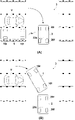
図8(A)は、S15の移動軌跡の設定例を示す説明図である。制御ユニット17は、検知ユニット18の検知結果から駐車場3内の平面座標を設定し、トレーラ1、牽引車2、各駐車スペース30、障害物の位置を平面座標上で特定する。そして、制御ユニット17は、例えば、トレーラ1の停車位置から駐車スペース30aにトレーラ1を移動するための1又は複数の移動軌跡の候補を演算する。そして、牽引車2から距離rの範囲4内にトレーラ1が維持される移動軌跡を選択する。これにより、牽引車2の乗員がトレーラ1の挙動を監視し易くなる。図8(A)の移動軌跡50は、トレーラ1を真っ直ぐに後退させ、その後、右前方へ前進させ、その後、左後方へ後退させることで、駐車スペース30aにトレーラ1を移動させる軌跡である。
FIG. 8A is an explanatory diagram showing an example of setting the movement locus of S15. The
範囲4の中心は、図示の例の場合、牽引車2の中心位置である。牽引車2の中心位置として例えば、トレーラ1の車幅方向中央で、牽引車2の側に2mの位置を牽引車2の中心位置とみなしてもよい。また、範囲4の中心は牽引車2の後端部であってもよい。範囲4の半径である距離rは例えば6m~10mの範囲内の距離である。
The center of the range 4 is the center position of the towing
牽引車2から距離rの範囲4内にトレーラ1が維持される移動軌跡とは、トレーラ1の全体が範囲4内に維持される軌跡であってもよいが、本実施形態ではトレーラ1の一部が範囲4内に維持される軌跡としている。図8(B)の移動軌跡51は、範囲4内にトレーラ1が維持されない移動軌跡の例である。移動軌跡51は、トレーラ1を真っ直ぐに後退させ、その後、右前方へ前進させ、その後、左後方へ後退させることで、駐車スペース30aにトレーラ1を移動させる軌跡である。トレーラ1を真っ直ぐに後退させたときに、トレーラ1の全体が範囲4外に位置するので、移動軌跡51は基本的に設定されない。
The movement locus in which the
範囲4内にトレーラ1が維持される移動軌跡を設定できない場合、制御ユニット17はトレーラ1と牽引車2が共に移動する区間を含む移動軌跡を設定する。トレーラ1に牽引車2を追従させることで、トレーラ1の近くに牽引車2が存在することを維持する。図9(A)及び図9(B)はその説明図である。
When the movement locus in which the
図9(A)の例では牽引車2の乗員がトレーラ1の駐車スペースとして駐車スペース30gを選択した場合を想定している。駐車スペース30gは、牽引車2の停車位置から距離r以上離れており、範囲4内にトレーラ1が維持される移動軌跡が存在しない。こうした場合、制御ユニット17は、図9(B)に示す移動軌跡52を設定する。なお、周辺障害物の存在によって、範囲4内にトレーラ1が維持される移動軌跡が存在しない場合も同様である。
In the example of FIG. 9A, it is assumed that the occupant of the towing
移動軌跡52は、トレーラ1と牽引車2が共に移動する区間52aを含む。トレーラ1の制御ユニット17は、車車間通信により牽引車2の制御ユニット25に対して、トレーラ1と共に、区間52aだけ移動(図示の例では後退)することの指示を送信する。指示を受信した牽引車2の制御ユニット25は、区間52aだけトレーラ1と協働的に牽引車2を移動させる。牽引車2の移動は、制御ユニット25が自動運転により行ってもよいし、牽引車2の運転者に入出力装置28によって移動を促してもよい。運転者に移動を促す場合、牽引車2の停止については制御ユニット25が制動装置24による制動を支援してもよい。
The
トレーラ1と牽引車2が区間52aだけ移動すると牽引車2は停車し、トレーラ1のみが駐車スペース30gへ移動する。この移動においては、範囲4内にトレーラ1を維持することが可能である。図9(B)の例では、区間52aの移動後、トレーラ1を真っ直ぐに後退させ、その後、右前方へ前進させ、その後、左後方へ後退させることで、駐車スペース30gにトレーラ1を移動させる軌跡である。
When the
このように、トレーラ1を駐車スペース30へ移動させる際のトレーラ1及び牽引車2の停車位置によって、範囲4内にトレーラ1が維持される移動軌跡を設定できない場合、牽引車2を一定区間、共に移動させることで、範囲4内にトレーラ1を維持する移動軌跡を設定することができる。
As described above, when the movement locus in which the
次に、制御ユニット17が、トレーラ1と牽引車2が共に移動する区間を含む移動軌跡を設定する場合の別の例について説明する。トレーラ1を駐車スペース30に移動させる際、周辺の障害物の存在によっては、トレーラ1を何度も切り返す必要が生じ得る。このような場合、牽引車2の乗員がトレーラ1が駐車スペース30に移動させることができるのかどうか、不安に感じる場合がある。そこで、トレーラ1の駐車スペース30への移動距離が所定距離以上となる場合は、トレーラ1と牽引車2が共に移動する区間を含む移動軌跡を設定する。所定距離としては、例えば、15m~20mの範囲内の距離である。図10(A)及び図10(B)はその説明図である。
Next, another example in which the
図10(A)は、駐車スペース30hへのトレーラ1の移動軌跡の選択候補として、移動軌跡53が演算された状況を示している。移動軌跡53は、図8(A)等で説明した範囲4内にトレーラ1が維持される移動軌跡である。しかし、移動軌跡53はトレーラ1の切り返しを多く含み、トレーラ1を真っ直ぐに後退させ、その後、右前方へ前進させ、その後、左後方へ後退させ、その位置から前進させ、その後、左後方へ後退させている。その結果、移動軌跡53は移動開始から移動終了までの距離が長い軌跡である。こうした場合、制御ユニット17は、図10(B)に示す移動軌跡54を設定する。
FIG. 10A shows a situation in which the
移動軌跡54は、トレーラ1と牽引車2が共に移動する区間54aを含む。トレーラ1の制御ユニット17は、車車間通信により牽引車2の制御ユニット25に対して、トレーラ1と共に、区間54aだけ移動(図示の例では前進)することの指示を送信する。指示を受信した牽引車2の制御ユニット25は、区間54aだけトレーラ1と協働的に牽引車2を移動させる。牽引車2の移動は、制御ユニット25が自動運転により行ってもよいし、牽引車2の運転者に入出力装置28によって移動を促してもよい。運転者に移動を促す場合、牽引車2の停止については制御ユニット25が制動装置24による制動を支援してもよい。
The
トレーラ1と牽引車2が区間54aだけ移動すると牽引車2は停車し、トレーラ1のみが駐車スペース30hへ移動する。この移動においては、範囲4内にトレーラ1を維持することが可能である。図10(B)の例では、区間54aの移動後、トレーラ1を真っ直ぐに後退させ、その後、右前方へ前進させ、その後、左後方へ後退させることで、駐車スペース30hにトレーラ1を移動させる軌跡である。
When the
なお、図10(A)及び図10(B)は、トレーラ1の駐車スペース30への移動距離が所定距離以上となる場合は、トレーラ1と牽引車2が共に移動する区間を含む移動軌跡を設定する例としたが、距離を基準とせず、トレーラ1の切り返しの回数(例えば5回以上)を基準としてトレーラ1と牽引車2が共に移動する区間を含む移動軌跡を設定してもよい。
In addition, FIG. 10A and FIG. 10B show a movement locus including a section in which the
次に、図7のS16の移動制御並びにS5の対応制御の処理例について図11を参照して説明する。図11のS161~S163は図7のS16の移動制御の例を示し、S51~S53は図7のS5の対応制御の例を示している。 Next, a processing example of the movement control of S16 of FIG. 7 and the correspondence control of S5 will be described with reference to FIG. S161 to S163 in FIG. 11 show an example of the movement control of S16 of FIG. 7, and S51 to S53 show an example of the correspondence control of S5 of FIG.
トレーラ1の制御ユニット17は、図7のS15で移動軌跡を設定すると、S161において、設定した移動軌跡がトレーラ1と牽引車2とを同時に移動する区間(図9(B)の区間52aや図10(B)の区間53a)を含むか否かを判定し、含まない場合はS162へ進み、含む場合はS163へ進む。
When the movement locus is set in S15 of FIG. 7, the
S162でトレーラ1の制御ユニット17は移動制御1を実行する。移動制御1で制御ユニット17は、図8(A)に例示したように、牽引車2の移動を要せずにトレーラ1を、S15で設定した移動軌跡に従って移動させる。トレーラ1の移動中、牽引車2が移動してしまうと、トレーラ1から牽引車2が離れてしまう場合がある。そこで、トレーラ1の制御ユニット17は、牽引車2の制御ユニット25に対して、トレーラ1が駐車スペース30へ移動中であることを示す移動中情報を送信する。この移動中情報は、トレーラ1が移動中、周期的に送信されるものであってもよいし、トレーラ1の移動開始の際と、移動終了の際に送信されてもよい。移動中情報を受信した牽引車2の制御ユニット25は、停車中の牽引車2の発進を禁止し、トレーラ1の移動が終了すると発進禁止を解除する。発進禁止は、牽引車2の制御ユニット25が、パワーユニット22を停止させる、或いは、駆動輪である前輪20fへの駆動伝達を遮断(変速機をニュートラルにする等)することによって行ってもよい。或いは、牽引車2は発進可能であるものの、乗員に対して入出力装置28によって牽引車2の発進を行わないように警告したり、発進した場合はトレーラ1を停車させるものであってもよい。
In S162, the
S163でトレーラ1の制御ユニット17は移動制御2を実行する。移動制御2で制御ユニット17は、図9(B)や図10(B)に例示したように、牽引車2をトレーラ1と共に移動させる。このため、トレーラ1の制御ユニット17は牽引車2の制御ユニット25へ移動指示を送信する。移動指示を受信した牽引車2の制御ユニット25は、S52でトレーラ1と共に移動する。
In S163, the
トレーラ1と牽引車2の移動区間が終了すると牽引車2は停車する。トレーラ1の制御ユニット17は、トレーラ1単独を駐車スペース30へ移動させる制御を開始する。その際、S162の移動制御1と同様、牽引車2の制御ユニット25に対して、トレーラ1が駐車スペース30へ移動中であることを示す移動中情報を送信する。移動中情報を受信した牽引車2の制御ユニット25は、S53で停車中の牽引車2の発進を禁止し、トレーラ1の移動が終了すると発進禁止を解除する。以上により、図7のS16の移動制御並びにS5の対応制御が終了する。
When the moving section between the
<通信端末を利用した駐車指示>
上述した実施形態では、牽引車2の乗員がトレーラ1の駐車を指示する際、牽引車2の車載装置(入出力装置28及び制御ユニット25)を介して、トレーラ1の制御ユニット17に指示を送信する構成としたが(図7のS1~S4)、これに加えて、乗員の通信端末からもトレーラ1の制御ユニット17へ指示を送信可能であってもよい。図12(A)はその模式図である。
<Parking instructions using communication terminals>
In the above-described embodiment, when the occupant of the towing
図示の例の場合、牽引車2の乗員6は牽引車2から降車し、自身の通信端末7を用いた無線通信によりトレーラ1の制御ユニット17に指示を送信している。乗員6が牽引車2から降車しつつ、トレーラ1に駐車指示を送信できるようにしたことで、乗員6はトレーラ1の移動を監視し易い場所に移動できる。
In the case of the illustrated example, the
通信端末7は、例えばスマートフォンに代表される携帯端末である。図12(B)は通信端末7のブロック図である。通信端末7は、処理部71、記憶部72、通信部73、表示部74を含む。処理部71は、CPUに代表されるプロセッサであり、記憶部72に記憶されたプログラムを実行する。記憶部72は、RAM、ROMなどの記憶デバイスである。記憶部72に記憶されたプログラムには、トレーラ1の制御ユニット17に駐車指示を行うためのアプリケーションプログラムも含まれる。通信部73は、トレーラ1の通信装置19と通信可能な無線通信装置である。表示部74は、入力機能を備えた電子画像の表示装置であり、例えば、タッチパネル式ディスプレイである。
The
通信端末7が実行する処理としては、例えば、図7のS1~S4の処理を挙げることができる。その他の処理については、牽引車2の制御ユニット25が、トレーラ1の制御ユニット17との車車間通信により行うことができる。
Examples of the processes executed by the
<実施形態のまとめ>
上記実施形態は以下のトレーラを少なくとも開示する。
<Summary of embodiments>
The above embodiment discloses at least the following trailers.
1.上記実施形態のトレーラは、
機械的な連結なく牽引車(2)に対する自動追従走行が可能な電動自走式のトレーラ(1)であって、
周囲状況を検知する検知手段(18)と、
前記検知手段の検知結果に基づいて、駐車スペースを認識する認識手段(17,S12)と、
駐車指示を受信する受信手段(19,17,S11)と、
前記受信手段が前記駐車指示を受信した場合に、前記牽引車及び前記トレーラが停車した位置から、前記認識手段が認識した駐車スペースへ前記トレーラを移動するための移動軌跡を設定する設定手段(17,S15)と、
前記設定手段が設定した移動軌跡に沿って前記トレーラを前記駐車スペースへ移動させる移動制御手段(17,S16)と、を備え、
前記設定手段は、前記牽引車と前記トレーラとの距離が所定範囲(4)内に維持される移動軌跡(50)を設定する。
この実施形態によれば、前記牽引車の乗員が前記トレーラの自動駐車を監視し易い技術を提供することができる。
1. 1. The trailer of the above embodiment is
It is an electric self-propelled trailer (1) that can automatically follow the towing vehicle (2) without mechanical connection.
Detection means (18) to detect the surrounding situation and
A recognition means (17, S12) that recognizes a parking space based on the detection result of the detection means,
Receiving means (19,17, S11) to receive parking instructions and
Setting means (17) for setting a movement locus for moving the trailer from the position where the towing vehicle and the trailer are stopped to the parking space recognized by the recognition means when the receiving means receives the parking instruction. , S15) and
A movement control means (17, S16) for moving the trailer to the parking space along a movement trajectory set by the setting means is provided.
The setting means sets a movement locus (50) in which the distance between the towing vehicle and the trailer is maintained within a predetermined range (4).
According to this embodiment, it is possible to provide a technique for easily monitoring the automatic parking of the trailer by the occupant of the towing vehicle.
2.上記実施形態では、
前記設定手段は、前記牽引車と前記トレーラとの距離が前記所定範囲内に維持される移動軌跡を設定できない場合は、前記トレーラと前記牽引車が共に移動する区間(52a)を含む移動軌跡(52)を設定する。
この実施形態によれば、前記牽引車及び前記トレーラの停車位置に起因して前記移動軌跡を設定できない場合であっても、前記牽引車を移動させることで、前記移動軌跡を設定することが可能となり、前記牽引車の乗員が前記トレーラの自動駐車を監視し易くすることができる。
2. 2. In the above embodiment,
When the setting means cannot set a movement locus in which the distance between the towing vehicle and the trailer is maintained within the predetermined range, the moving locus including a section (52a) in which the trailer and the towing vehicle move together (52a). 52) is set.
According to this embodiment, even when the movement locus cannot be set due to the stop positions of the towing vehicle and the trailer, the movement locus can be set by moving the towing vehicle. Therefore, it is possible to facilitate the occupant of the towing vehicle to monitor the automatic parking of the trailer.
3.上記実施形態では、
前記設定手段は、前記駐車スペースへの移動距離が所定距離以上となる場合は、前記トレーラと前記牽引車が共に移動する区間(54a)を含む移動軌跡(54)を設定する。
この実施形態によれば、前記トレーラが前記駐車スペースへ移動するための移動距離が長距離となり、前記牽引車の乗員を不安にさせる可能性がある場合は、前記牽引車を移動させることで、前記トレーラが単独で移動する距離を短くすることができ、前記牽引車の乗員の不安を解消することができる。
3. 3. In the above embodiment,
When the moving distance to the parking space is equal to or longer than a predetermined distance, the setting means sets a moving locus (54) including a section (54a) in which the trailer and the towing vehicle move together.
According to this embodiment, when the moving distance for the trailer to move to the parking space is long and there is a possibility that the occupant of the towing vehicle may be anxious, the towing vehicle may be moved. The distance that the trailer travels alone can be shortened, and the anxiety of the occupant of the towing vehicle can be eliminated.
4.上記実施形態のトレーラは、
前記設定手段が、前記トレーラと前記牽引車が共に移動する区間を含む移動軌跡を設定した場合に、前記牽引車の制御部(25)に前記トレーラと共に移動することの要求を送信する送信手段(19,17,S163)を備える。
この実施形態によれば、前記牽引車の前記制御部が、前記トレーラの駐車のために、その移動の必要性を認識し易くなる。
4. The trailer of the above embodiment is
When the setting means sets a movement locus including a section in which the trailer and the towing vehicle move together, a transmission means for transmitting a request to move with the trailer to the control unit (25) of the towing vehicle (25). 19,17, S163).
According to this embodiment, the control unit of the towing vehicle can easily recognize the necessity of its movement for parking the trailer.
5.上記実施形態のトレーラは、
前記トレーラが前記駐車スペースへ移動中であることを示す情報を前記牽引車の制御部に送信する送信手段(19,17,S162,S163)を備える。
この実施形態によれば、前記牽引車の前記制御部が、前記トレーラが駐車のために移動中であることを認識し易くなり、前記牽引車の停車の維持等、乗員が前記トレーラを監視し易い状態を維持し易くなる。
5. The trailer of the above embodiment is
A transmission means (19,17, S162, S163) for transmitting information indicating that the trailer is moving to the parking space to the control unit of the towing vehicle is provided.
According to this embodiment, the control unit of the towing vehicle can easily recognize that the trailer is moving for parking, and the occupant monitors the trailer, such as keeping the towing vehicle stopped. It becomes easier to maintain an easy state.
6.上記実施形態では、
前記受信手段は、前記牽引車の乗員の通信端末(7)から前記駐車指示を受信可能である。
この実施形態によれば、前記牽引車の乗員が、前記牽引車から降車して、前記トレーラに対して駐車指示を行うことができる。
6. In the above embodiment,
The receiving means can receive the parking instruction from the communication terminal (7) of the occupant of the towing vehicle.
According to this embodiment, the occupant of the towing vehicle can get off the towing vehicle and give a parking instruction to the trailer.
7.上記実施形態のトレーラは、
前記駐車スペースに駐車中に、前記牽引車の制御部から発進指示を受信した場合に、前記駐車スペースから前記トレーラを発進させ、前記牽引車に対する追従を開始させる発進制御手段(17,S18,S19)を備える。
7. The trailer of the above embodiment is
Starting control means (17, S18 , S19) that start the trailer from the parking space and start following the towing vehicle when a start instruction is received from the control unit of the towing vehicle while parked in the parking space. ).
この実施形態によれば、前記牽引車からの指示により、駐車中の前記トレーラを発進させて追従させることができるので、前記牽引車の乗員の利便性を向上できる。 According to this embodiment, the trailer in parking can be started and followed by an instruction from the towing vehicle, so that the convenience of the occupant of the towing vehicle can be improved.
以上、発明の実施形態について説明したが、発明は上記の実施形態に制限されるものではなく、発明の要旨の範囲内で、種々の変形・変更が可能である。 Although the embodiments of the invention have been described above, the invention is not limited to the above-described embodiments, and various modifications and changes can be made within the scope of the gist of the invention.
1 トレーラ、2 牽引車、17 制御ユニット、18 検知ユニット 1 trailer, 2 towing vehicle, 17 control unit, 18 detection unit
Claims (6)
周囲状況を検知する検知手段と、
前記検知手段の検知結果に基づいて、駐車スペースを認識する認識手段と、
駐車指示を受信する受信手段と、
前記受信手段が前記駐車指示を受信した場合に、前記牽引車及び前記トレーラが停車した位置から、前記認識手段が認識した駐車スペースへ前記トレーラを移動するための移動軌跡を設定する設定手段と、
前記設定手段が設定した移動軌跡に沿って前記トレーラを前記駐車スペースへ移動させる移動制御手段と、を備え、
前記設定手段は、前記牽引車と前記トレーラとの距離が所定範囲内に維持される移動軌跡を設定し、
前記設定手段は、前記牽引車と前記トレーラとの距離が前記所定範囲内に維持される移動軌跡を設定できない場合は、前記トレーラと前記牽引車が共に移動する区間を含む移動軌跡を設定する、
ことを特徴とするトレーラ。 It is an electric self-propelled trailer that can automatically follow a towing vehicle without mechanical connection.
Detection means to detect the surrounding situation and
A recognition means for recognizing a parking space based on the detection result of the detection means,
Receiving means to receive parking instructions and
When the receiving means receives the parking instruction, the setting means for setting the movement locus for moving the trailer from the position where the towing vehicle and the trailer are stopped to the parking space recognized by the recognition means, and the setting means.
A movement control means for moving the trailer to the parking space along a movement trajectory set by the setting means is provided.
The setting means sets a movement locus in which the distance between the towing vehicle and the trailer is maintained within a predetermined range.
When the setting means cannot set a movement locus in which the distance between the towing vehicle and the trailer is maintained within the predetermined range, the setting means sets a movement locus including a section in which the trailer and the towing vehicle move together.
A trailer that features that.
周囲状況を検知する検知手段と、
前記検知手段の検知結果に基づいて、駐車スペースを認識する認識手段と、
駐車指示を受信する受信手段と、
前記受信手段が前記駐車指示を受信した場合に、前記牽引車及び前記トレーラが停車した位置から、前記認識手段が認識した駐車スペースへ前記トレーラを移動するための移動軌跡を設定する設定手段と、
前記設定手段が設定した移動軌跡に沿って前記トレーラを前記駐車スペースへ移動させる移動制御手段と、を備え、
前記設定手段は、前記牽引車と前記トレーラとの距離が所定範囲内に維持される移動軌跡を設定し、
前記設定手段は、前記駐車スペースへの移動距離が所定距離以上となる場合は、前記トレーラと前記牽引車が共に移動する区間を含む移動軌跡を設定する、
ことを特徴とするトレーラ。 It is an electric self-propelled trailer that can automatically follow a towing vehicle without mechanical connection.
Detection means to detect the surrounding situation and
A recognition means for recognizing a parking space based on the detection result of the detection means,
Receiving means to receive parking instructions and
When the receiving means receives the parking instruction, the setting means for setting the movement locus for moving the trailer from the position where the towing vehicle and the trailer are stopped to the parking space recognized by the recognition means, and the setting means.
A movement control means for moving the trailer to the parking space along a movement trajectory set by the setting means is provided.
The setting means sets a movement locus in which the distance between the towing vehicle and the trailer is maintained within a predetermined range.
When the moving distance to the parking space is equal to or longer than a predetermined distance, the setting means sets a moving locus including a section in which the trailer and the towing vehicle move together.
A trailer that features that.
前記設定手段が、前記トレーラと前記牽引車が共に移動する区間を含む移動軌跡を設定した場合に、前記牽引車の制御部に前記トレーラと共に移動することの要求を送信する送信手段を備える、
ことを特徴とするトレーラ。 The trailer according to claim 1 or 2 .
The setting means includes a transmission means for transmitting a request to move with the trailer to the control unit of the towing vehicle when a movement locus including a section in which the trailer and the towing vehicle move together is set.
A trailer that features that.
周囲状況を検知する検知手段と、
前記検知手段の検知結果に基づいて、駐車スペースを認識する認識手段と、
駐車指示を受信する受信手段と、
前記受信手段が前記駐車指示を受信した場合に、前記牽引車及び前記トレーラが停車した位置から、前記認識手段が認識した駐車スペースへ前記トレーラを移動するための移動軌跡を設定する設定手段と、
前記設定手段が設定した移動軌跡に沿って前記トレーラを前記駐車スペースへ移動させる移動制御手段と、を備え、
前記設定手段は、前記牽引車と前記トレーラとの距離が所定範囲内に維持される移動軌跡を設定し、
前記駐車スペースに駐車中に、前記牽引車の制御部から発進指示を受信した場合に、前記駐車スペースから前記トレーラを発進させ、前記牽引車に対する追従を開始させる発進制御手段を備える、
ことを特徴とするトレーラ。 It is an electric self-propelled trailer that can automatically follow a towing vehicle without mechanical connection.
Detection means to detect the surrounding situation and
A recognition means for recognizing a parking space based on the detection result of the detection means,
Receiving means to receive parking instructions and
When the receiving means receives the parking instruction, the setting means for setting the movement locus for moving the trailer from the position where the towing vehicle and the trailer are stopped to the parking space recognized by the recognition means, and the setting means.
A movement control means for moving the trailer to the parking space along a movement trajectory set by the setting means is provided.
The setting means sets a movement locus in which the distance between the towing vehicle and the trailer is maintained within a predetermined range.
A start control means for starting the trailer from the parking space and starting to follow the towing vehicle when a start instruction is received from the control unit of the towing vehicle while parked in the parking space is provided .
A trailer that features that.
前記トレーラが前記駐車スペースへ移動中であることを示す情報を前記牽引車の制御部に送信する送信手段を備える、
ことを特徴とするトレーラ。 The trailer according to any one of claims 1 to 4 .
A transmission means for transmitting information indicating that the trailer is moving to the parking space to the control unit of the towing vehicle is provided.
A trailer that features that.
前記受信手段は、前記牽引車の乗員の通信端末から前記駐車指示を受信可能である、
ことを特徴とするトレーラ。 The trailer according to any one of claims 1 to 5 .
The receiving means can receive the parking instruction from the communication terminal of the occupant of the towing vehicle.
A trailer that features that.
Priority Applications (3)
| Application Number | Priority Date | Filing Date | Title |
|---|---|---|---|
| JP2019113011A JP7042774B2 (en) | 2019-06-18 | 2019-06-18 | Trailer |
| DE102020206828.3A DE102020206828A1 (en) | 2019-06-18 | 2020-06-02 | pendant |
| US16/898,923 US11458939B2 (en) | 2019-06-18 | 2020-06-11 | Trailer |
Applications Claiming Priority (1)
| Application Number | Priority Date | Filing Date | Title |
|---|---|---|---|
| JP2019113011A JP7042774B2 (en) | 2019-06-18 | 2019-06-18 | Trailer |
Publications (3)
| Publication Number | Publication Date |
|---|---|
| JP2020203618A JP2020203618A (en) | 2020-12-24 |
| JP2020203618A5 JP2020203618A5 (en) | 2021-05-20 |
| JP7042774B2 true JP7042774B2 (en) | 2022-03-28 |
Family
ID=73654122
Family Applications (1)
| Application Number | Title | Priority Date | Filing Date |
|---|---|---|---|
| JP2019113011A Active JP7042774B2 (en) | 2019-06-18 | 2019-06-18 | Trailer |
Country Status (3)
| Country | Link |
|---|---|
| US (1) | US11458939B2 (en) |
| JP (1) | JP7042774B2 (en) |
| DE (1) | DE102020206828A1 (en) |
Families Citing this family (2)
| Publication number | Priority date | Publication date | Assignee | Title |
|---|---|---|---|---|
| KR20220045605A (en) * | 2020-10-05 | 2022-04-13 | 현대자동차주식회사 | System and method for controlling driving of vehicle |
| US20220250618A1 (en) * | 2021-02-05 | 2022-08-11 | Bendix Commercial Vehicle Systems Llc | Suppression of LDW/LKA Prior to Tight Cornering of a Commercial Vehicle |
Citations (3)
| Publication number | Priority date | Publication date | Assignee | Title |
|---|---|---|---|---|
| JP2000311299A (en) | 1999-04-28 | 2000-11-07 | Honda Motor Co Ltd | Convoy forming method for automatic following traveling system |
| US20150115571A1 (en) | 2013-10-24 | 2015-04-30 | GM Global Technology Operations LLC | Smart tow |
| WO2019105665A1 (en) | 2017-11-28 | 2019-06-06 | Jaguar Land Rover Limited | Parking assist method and apparatus |
Family Cites Families (12)
| Publication number | Priority date | Publication date | Assignee | Title |
|---|---|---|---|---|
| JPH06219348A (en) | 1993-01-22 | 1994-08-09 | Mazda Motor Corp | Towing vehicle and towing vehicle system |
| JPH10157652A (en) | 1996-12-03 | 1998-06-16 | Honda Motor Co Ltd | Maneuvering device for trailer |
| JP3524400B2 (en) | 1998-09-30 | 2004-05-10 | 本田技研工業株式会社 | Automatic following system |
| JP5515782B2 (en) | 2010-01-26 | 2014-06-11 | トヨタ自動車株式会社 | Steering device |
| DE102014224099A1 (en) | 2014-11-26 | 2016-06-02 | Robert Bosch Gmbh | Method and device for operating multiple vehicles |
| DE102015114308A1 (en) | 2015-08-28 | 2017-03-02 | Reich Kg, Regel- Und Sicherheitstechnik | A method of operating an auxiliary drive for a trailer and system for driving at least one wheel of such a trailer |
| DE102016102847A1 (en) * | 2016-02-18 | 2017-08-24 | Nüwiel GbR (vertretungsberechtigte Gesellschafter: Sandro Rabbiosi, 21073 Hamburg; Fahad Aman Khan, 21073 Hamburg; Natalia Tomiyma, 22303 Hamburg) | Method for controlling a driven trailer, a motor-driven trailer and a sensor unit for this purpose |
| JP6629156B2 (en) | 2016-08-31 | 2020-01-15 | アイシン精機株式会社 | Parking assistance device |
| DE102017200168A1 (en) | 2017-01-09 | 2018-07-12 | Volkswagen Aktiengesellschaft | Method and system for providing at least partially automated guidance of a follower vehicle |
| US10899384B2 (en) * | 2017-07-13 | 2021-01-26 | Continental Automotive Systems, Inc. | Trailer reverse assist with follow-me system |
| CN111108023B (en) * | 2017-10-10 | 2022-04-12 | 株式会社爱信 | Parking assist apparatus |
| EP3953195A1 (en) * | 2019-04-12 | 2022-02-16 | Continental Automotive Systems, Inc. | Autonomous vehicle-trailer maneuvering and parking |
-
2019
- 2019-06-18 JP JP2019113011A patent/JP7042774B2/en active Active
-
2020
- 2020-06-02 DE DE102020206828.3A patent/DE102020206828A1/en not_active Withdrawn
- 2020-06-11 US US16/898,923 patent/US11458939B2/en active Active
Patent Citations (3)
| Publication number | Priority date | Publication date | Assignee | Title |
|---|---|---|---|---|
| JP2000311299A (en) | 1999-04-28 | 2000-11-07 | Honda Motor Co Ltd | Convoy forming method for automatic following traveling system |
| US20150115571A1 (en) | 2013-10-24 | 2015-04-30 | GM Global Technology Operations LLC | Smart tow |
| WO2019105665A1 (en) | 2017-11-28 | 2019-06-06 | Jaguar Land Rover Limited | Parking assist method and apparatus |
Also Published As
| Publication number | Publication date |
|---|---|
| JP2020203618A (en) | 2020-12-24 |
| US20200398803A1 (en) | 2020-12-24 |
| DE102020206828A1 (en) | 2020-12-24 |
| US11458939B2 (en) | 2022-10-04 |
Similar Documents
| Publication | Publication Date | Title |
|---|---|---|
| JP7068233B2 (en) | Trailer | |
| US11543816B2 (en) | Signaling information on a detected parking space to the operator of a remote control for a parking assistance system which can be controlled by remote control for automatically parking a motor vehicle | |
| JP7184784B2 (en) | Method and system for remotely operating a vehicle | |
| CN109795487B (en) | Device and method for controlling train travel of vehicles | |
| JP6260544B2 (en) | Automatic driving device | |
| US9944294B2 (en) | Vehicle traveling control apparatus | |
| JP2021527586A (en) | Environmentally active sensing type parking lot automatic parking system | |
| JP5471462B2 (en) | Automatic parking equipment | |
| CN107176099B (en) | Vehicle travel control device | |
| JP6047083B2 (en) | Parking assistance system | |
| CN109421800B (en) | Steering assist device | |
| CN102027458A (en) | Method and apparatus for driver control of a limited-ability autonomous vehicle | |
| CN112440981A (en) | Method for executing automatic passenger-replacing parking | |
| JP7042774B2 (en) | Trailer | |
| US20190161086A1 (en) | Method and mechanism for assisted performance of a reverse-turning maneuver of a vehicle | |
| JP2017165277A (en) | Traveling control device of vehicle | |
| CN112208511A (en) | Auxiliary hooking system with switching process for interrupted operation | |
| JP2017165393A (en) | Traveling control device of vehicle | |
| CN113825691B (en) | Vehicle travel control method and travel control device | |
| US20200247197A1 (en) | System and methods for vehicle alignment control | |
| US11584400B2 (en) | Autonomous vehicle | |
| CN111845722B (en) | Automatic automobile driving method, automatic automobile parking method and electronic equipment | |
| US20190389262A1 (en) | System and method for positioning a vehicle with reduced variation | |
| JP2014184746A (en) | Parking assist apparatus, and control device | |
| KR20200142154A (en) | Driver assistance system and control method for the same |
Legal Events
| Date | Code | Title | Description |
|---|---|---|---|
| RD02 | Notification of acceptance of power of attorney |
Free format text: JAPANESE INTERMEDIATE CODE: A7422 Effective date: 20210103 |
|
| A521 | Request for written amendment filed |
Free format text: JAPANESE INTERMEDIATE CODE: A523 Effective date: 20210125 |
|
| A621 | Written request for application examination |
Free format text: JAPANESE INTERMEDIATE CODE: A621 Effective date: 20210329 |
|
| A521 | Request for written amendment filed |
Free format text: JAPANESE INTERMEDIATE CODE: A523 Effective date: 20210409 |
|
| A131 | Notification of reasons for refusal |
Free format text: JAPANESE INTERMEDIATE CODE: A131 Effective date: 20220207 |
|
| A521 | Request for written amendment filed |
Free format text: JAPANESE INTERMEDIATE CODE: A523 Effective date: 20220214 |
|
| TRDD | Decision of grant or rejection written | ||
| A01 | Written decision to grant a patent or to grant a registration (utility model) |
Free format text: JAPANESE INTERMEDIATE CODE: A01 Effective date: 20220304 |
|
| A61 | First payment of annual fees (during grant procedure) |
Free format text: JAPANESE INTERMEDIATE CODE: A61 Effective date: 20220315 |
|
| R150 | Certificate of patent or registration of utility model |
Ref document number: 7042774 Country of ref document: JP Free format text: JAPANESE INTERMEDIATE CODE: R150 |