EP3135569B2 - Procédé de fonctionnement d'un entraînement auxiliaire pour une remorque et système d'entrainement d'au moins une roue d'une telle remorque - Google Patents
Procédé de fonctionnement d'un entraînement auxiliaire pour une remorque et système d'entrainement d'au moins une roue d'une telle remorque Download PDFInfo
- Publication number
- EP3135569B2 EP3135569B2 EP16183954.3A EP16183954A EP3135569B2 EP 3135569 B2 EP3135569 B2 EP 3135569B2 EP 16183954 A EP16183954 A EP 16183954A EP 3135569 B2 EP3135569 B2 EP 3135569B2
- Authority
- EP
- European Patent Office
- Prior art keywords
- trailer
- operating element
- user
- function
- auxiliary drive
- Prior art date
- Legal status (The legal status is an assumption and is not a legal conclusion. Google has not performed a legal analysis and makes no representation as to the accuracy of the status listed.)
- Active
Links
Images
Classifications
-
- B—PERFORMING OPERATIONS; TRANSPORTING
- B62—LAND VEHICLES FOR TRAVELLING OTHERWISE THAN ON RAILS
- B62D—MOTOR VEHICLES; TRAILERS
- B62D59/00—Trailers with driven ground wheels or the like
- B62D59/04—Trailers with driven ground wheels or the like driven from propulsion unit on trailer
Definitions
- the present invention relates to a method for operating an auxiliary drive for a trailer, in particular a caravan, a boat trailer, a sales van, a transport trailer or a car transport trailer, as well as a system for driving at least one wheel of such a trailer.
- auxiliary drives for trailers are already well known from the general state of the art.
- Such an auxiliary drive is used in particular to move the trailer in a state in which the trailer is uncoupled from a tractor. This is particularly advantageous for trailers that are moved, for example, on campsites or caravan parking lots and have to be maneuvered in the process.
- at least one drive element can be brought into interaction with at least one wheel of the trailer.
- the drive element is, for example, a drive roller of the auxiliary drive, wherein the drive roller is, for example, moved into contact with the wheel and kept in contact.
- the drive roller is driven with the aid of at least one motor, in particular an electric motor, of the auxiliary drive, whereby the wheel interacting with the drive roller is rotated or moved. This allows the trailer to be maneuvered precisely in the uncoupled state.
- the EN 20 2012 006 089 U1 discloses a shunting system for a trailer, with at least two shunting drives that can be arranged on the trailer, each with a drive roller, wherein each drive roller can be adjusted to a wheel of the trailer in order to drive it.
- a remote control unit for remote-controlled parking of a motor vehicle is known, with a housing and with elements for actuation.
- the EN 10 2012 007 986 A1 a maneuvering system for the automated maneuvering of a motor vehicle is known, with a vehicle-side control device which is designed to output control signals to a drive and/or steering device of the motor vehicle and thereby automatically carry out a maneuvering process of the motor vehicle.
- the EP 1 790 555 A1 an arrangement for manoeuvring a trailer with two wheels on each side. Furthermore, the EN 20 2012 006 089 U1 a shunting drive for a trailer is known. In addition, the US 2014/0338793 A1 a method of providing a computing device with wireless control of an operation of a control device.
- the object of the present invention is to provide a method and a system by means of which a trailer can be moved, in particular maneuvered, in a particularly simple and safe manner.
- a first aspect of the invention relates to a method for operating an auxiliary drive for a trailer, in particular a caravan, a boat trailer, a sales van, a transport trailer or a car transport trailer.
- at least one mobile terminal connected to the auxiliary drive via a wireless communication connection provides at least one functional control element by means of which at least one function of the auxiliary drive can be effected by a user or a person via the mobile terminal and the wireless connection.
- the mobile terminal provides at least one safety control element that is different from the functional control element, wherein the functional control element is enabled to effect the at least one function depending on at least one actuation or operation of the safety control element by the user.
- the functional control element basically serves to effect the at least one function of the auxiliary drive. To do this, the user operates or actuates the functional control element by, for example, touching and in particular pressing the functional control element.
- the at least one function is, for example, a drive function, in the context of which at least one wheel, i.e. a ground contact element of the trailer, is rotated and thus moved by means of the auxiliary drive. Since the trailer is supported on a roadway or ground via the wheel, for example, the trailer is driven or moved by driving or rotating the wheel and can thus be maneuvered, for example. In particular, the trailer can be maneuvered in its uncoupled state, in which the trailer is not coupled to a tractor.
- a drive function in the context of which at least one wheel, i.e. a ground contact element of the trailer, is rotated and thus moved by means of the auxiliary drive. Since the trailer is supported on a roadway or ground via the wheel, for example, the trailer is driven or moved by driving or rotating the wheel and can thus be maneuvered, for example. In particular, the trailer can be maneuvered in its uncoupled state, in which the trailer is not coupled to a tractor.
- the at least one function can be a so-called pivoting function, within the framework of which at least one drive element such as a drive roller of the auxiliary drive is moved in interaction and, for example, in contact with at least one wheel of the trailer.
- the auxiliary drive executes the at least one function when and preferably only when the functional control element is or is enabled for effecting the at least one function.
- the functional control element is enabled when the user operates or actuates the safety control element and, for example, touches and in particular presses it. This means, for example, that the functional control element is fundamentally or in an initial state or basic state blocked or deactivated with regard to the effecting of the at least one function. If the function control element is in this initial state or basic state and the user operates the function control element, function control element in the active state and the user operates the function control element while the function control element is in the initial state, the auxiliary drive does not carry out the at least one function. In other words, the auxiliary drive then does not carry out the at least one function.
- an active state of the functional control element is set or activated, for example.
- the functional control element is transferred to an active state.
- the at least one function is effected or the auxiliary drive carries out the at least one function.
- the auxiliary drive carries out the at least one function if and preferably only if the functional control element is in the active state, which in turn is effected by the safety control element being actuated. This enables particularly safe operation of the auxiliary drive as well as safe driving and thus maneuvering of the trailer, since, for example, unintentional and unwanted triggering of the at least one function can be avoided.
- the safety control element acts as a dead man's switch to ensure that both the functional control element and the safety control element must each be operated at least once in order to actually carry out at least one function.
- This makes it possible, for example, to distinguish between unwanted and unintentional operations of the functional control element by the user and intentional or intended operations, since in the case of unwanted or unintentional operations, for example, the user operates the functional control element but not the safety control element. In the case of intentional and desired operations, however, the user operates both the functional control element and the safety control element.
- the mobile device is, for example, a simple remote control, which, for example, only has the function of remotely controlling the auxiliary drive.
- the mobile device is, for example, a mobile communication device such as a cell phone or a smartphone, which is used to remotely control the auxiliary drive.
- a mobile communication device can also be used, for example, to make telephone calls.
- the mobile device is a tablet or a tablet PC, a laptop, a notebook or the like.
- the functional control element can be transferred from the basic state to the active state as a result of at least one actuation of the safety control element by the user and to be held in the active state for a period of time following the actuation of the safety control element or for a period of time following the termination of the actuation of the safety control element.
- This period of time is, for example, at least two seconds.
- the functional control element is in the active state - temporarily, namely during the predeterminable period of time - even when the safety control element is no longer being actuated by the user.
- the at least one function can therefore be effected by actuating the functional control element during the predeterminable period of time even when the safety control element is not being actuated by the user.
- the safety control element is provided as a control surface on a touch-sensitive screen of the mobile terminal.
- the configurations and advantages described for the functional control element designed as a control surface also apply to the safety control element designed as a control surface and vice versa. If the user touches the touch-sensitive screen in the area of the safety control element designed as a control surface, an actuation of the safety control element by the user can be reliably detected by means of the touch-sensitive screen. If the user no longer touches the touch-sensitive screen or if the distance between the user and the touch-sensitive screen exceeds the predeterminable threshold value, this detects that the actuation of the functional control element or the safety control element has ended. If the user stops activating the safety control element and/or the functional control element, the execution of at least one function is stopped.
- the invention provides that an actuation by the user of the released functional control element, i.e. one in the active state, is displayed by means of at least one symbol on a display of the mobile terminal. This visually communicates to the user that he is actually actuating the functional control element in order to actually effect the at least one function. Overall, it is thus possible to visually communicate the operation of the auxiliary drive to the user, so that particularly safe operation can be achieved.
- the invention also provides that the activation of the released functional control element by the user is displayed by means of the at least one symbol in an area of the mobile terminal that is different from the functional control element and the safety control element.
- the user can be reliably visually informed, even if the user covers the functional control element and the safety control element with his fingers, that he is activating both the safety control element and the functional control element and is thus actually activating the at least one function.
- the respective operations of the functional control element and the safety control element are recorded by the mobile device and in particular represent inputs into the mobile device.
- the function control element is released while the user is holding the safety control element operated, wherein the functional control element is blocked for executing the at least one function, while an actuation of the safety control element by the user does not take place.
- the functional control element is in the active state for as long as and only as long as the user operates the safety control element or an actuation of the control element by the user is detected.
- the user must therefore operate both the functional control element and the safety control element at the same time in order to actually execute the at least one function.
- the auxiliary drive carries out the at least one function if and preferably only if a simultaneous actuation of the safety control element and the functional control element by the user is detected by means of the mobile terminal.
- the user must therefore confirm the function control element and the safety control element simultaneously, for example using two fingers of one hand or using at least one finger of his first hand and at least one finger of his second hand, in order to actually carry out at least one function.
- This makes it possible to achieve particularly safe operation of the auxiliary drive, as the risk of the user's hands getting caught between moving components can be kept particularly low. In particular, this makes it possible to keep the risk of functions of the auxiliary drive being triggered inadvertently, for example when the user puts the mobile device in his pocket.
- the functional control element is blocked immediately after the user has finished activating the safety control element, i.e. it is switched or transferred to the basic state.
- the functional control element is switched from the active state to the basic state immediately, i.e. at least with almost no time delay and in particular without a specific time delay, when the user has finished activating the safety control element or when the user has detected that the safety control element has finished activating it. This enables particularly safe operation of the auxiliary drive.
- an actuation of the safety control element by the user is displayed by means of at least one symbol on the display of the mobile device.
- the at least one symbol is displayed on the display of the mobile device. This can visually communicate to the user that he is actually activating the safety control element. The user is thus visually communicated that the function control element is in the active state and the user can actually carry out the at least one function.
- the wireless communication connection is, for example, a radio connection or a wireless communication connection via radio technology.
- the wireless communication connection can be a connection via Bluetooth, WLAN (Wireless Local Area Network) or the like.
- the wireless communication connection means that the mobile device is not connected to the auxiliary drive via a physical line, but rather the The mobile terminal is connected to the auxiliary drive without such a physical cable, for example by means of radio technology, so that the mobile terminal can, for example, wirelessly exchange data with the auxiliary drive via the wireless communication connection.
- the functional control element and/or the safety control element can be designed, for example, as a mechanical control element, in particular as a button, wherein the mechanical control element can be moved, for example, relative to a housing of the mobile terminal between at least two different positions.
- the mechanical control element can be designed, in particular, as a button.
- the functional control element is provided as a control surface on a touch-sensitive screen of the mobile device.
- the touch-sensitive screen can be used, for example, to detect when the user approaches the mobile device and in particular the touch-sensitive screen. Such an approach is detected, for example, when a distance between the user and the touch-sensitive screen falls below a predeterminable threshold value, with the user, for example, touching the touch-sensitive screen.
- a distance between the user and the touch-sensitive screen in the area of the functional control element designed as a control surface falls below the predeterminable threshold value or if the user, for example, touches the touch-sensitive screen in the area of the functional control element designed as a control surface, an actuation of the functional control element by the user using the touch-sensitive screen is detected. This can ensure safe and simple operation of the auxiliary drive.
- a second aspect of the invention relates to a system for driving at least one wheel of a trailer, in particular a caravan, a boat trailer, a sales van, a transport trailer or a car transport trailer.
- the system comprises at least one auxiliary drive for driving the wheel.
- the system also comprises at least one mobile terminal that can be connected to the auxiliary drive via a wireless communication connection and has at least one functional control element by means of which at least one function of the auxiliary drive can be effected by a user via the mobile terminal and the wireless connection.
- the mobile terminal has at least one safety control element that is different from the functional control element, wherein the system is designed to release the functional control element depending on at least one actuation of the safety control element by the user for effecting the at least one function.
- the system is designed to carry out a method according to the invention.
- Advantages and embodiments of the first aspect of the invention are to be regarded as advantages and embodiments of the second aspect of the invention and vice versa.
- particularly safe operation of the auxiliary drive can be achieved by means of the system according to the invention, since the user does not only have to actuate the functional control element, but both the functional control element and the safety control element in order to actually effect the at least one function of the auxiliary drive.
- the safety control element is designed as a control surface on a touch-sensitive screen of the mobile terminal.
- the mobile terminal has a display with at least one display area that is different from the functional control element and the safety control element.
- an actuation of the enabled functional control element by the user can be displayed by means of at least one symbol on the display of the mobile terminal.
- the functional control element is designed as a control surface on a touch-sensitive screen of the mobile terminal. This makes it possible to achieve a particularly high level of functionality, since the area of the control surface can be used for different displays. Furthermore, this makes it possible to achieve particularly safe operation, since the actuation and termination of the actuation of the functional control element can be reliably detected.
- This display is, for example, the previously mentioned touch-sensitive screen, which is also commonly referred to as a touch display or touch screen.
- a further embodiment is characterized in that the at least one function is designed as a rotation function, by means of which a rotation of the trailer can be effected via the auxiliary drive, while a translational movement of the trailer is at least substantially avoided.
- the rotation function causes a rotation on the spot, so that the trailer rotates about its vertical axis or vertical direction, without essentially moving translationally, i.e. forwards or backwards.
- the trailer can be rotated in a particularly small space and aligned as required without the trailer colliding with other objects. This makes particularly safe operation possible.
- auxiliary drive drives the wheel in one direction of rotation during the turning function, while the auxiliary drive does not drive a second wheel of the trailer that is opposite the wheel in the transverse direction of the trailer.
- This has proven to be particularly advantageous for multi-axle trailers, which can then be turned in a particularly space-saving manner using the turning function.
- Such a multi-axle trailer has at least two axles that are arranged one after the other in the longitudinal direction of the vehicle, or one behind the other, with such an axle having at least two ground contact elements in the form of wheels that are arranged opposite one another in the transverse direction of the trailer.
- auxiliary drive during the rotation function, drives the wheel in a first direction of rotation and a second wheel, which is opposite the wheel in the transverse direction of the trailer, in a second direction of rotation opposite to the first direction of rotation.
- This has proven to be particularly advantageous for single-axle trailers, whereby such a single-axle trailer has exactly one axle.
- Such an axle comprises at least two ground contact elements in the form of wheels, which are arranged opposite one another in the transverse direction of the trailer and thus in the transverse direction of the vehicle and over which the trailer rolls onto the ground when driving.
- a further embodiment is characterized in that the function is designed as a maneuvering function, in which the auxiliary drive drives the wheel in one direction of rotation at a first speed and a second wheel opposite the wheel in the transverse direction of the trailer in the direction of rotation at a second speed that is different from the first speed and is greater than zero.
- the auxiliary drive drives the wheels in the same direction, but the first wheel is driven more strongly or at a higher speed than the second wheel, so that the trailer is moved forwards or backwards, but not along a straight line, but along a curve. This makes it particularly easy to maneuver the trailer.
- the second speed is at least one tenth and at most three eighths of the first speed.
- the auxiliary drive has at least one further function, which is designed as a drive function, in which the auxiliary drive drives the trailer along a straight line by driving the wheels, i.e. the first wheel and the second wheel, at a third speed that corresponds to 100%.
- the trailer is thus moved backwards or forwards and at least essentially along a straight line.
- the trailer does not corner as a result of the auxiliary drive.
- the shunting function provides that the first speed is in a range of 80% to 100% of the third speed and the second speed is in a range of 10% to 30% of the third speed. This allows the trailer to corner particularly advantageously as part of the shunting function.
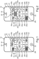
- Fig.1 shows a schematic plan view of a mobile terminal, designated as a whole by 10, which is designed as a mobile telecommunications terminal in the present case.
- the mobile terminal 10 is designed as a smartphone and is therefore designed to establish a telephone connection via radio technology.
- the mobile terminal 10 comprises a housing 12 and a display 14, which is designed as a touch-sensitive screen.
- the mobile terminal 10 has a Fig.1 by a double arrow 16, wherein at least one loudspeaker 18 for reproducing sounds is arranged above the display 14 in relation to this vertical direction.
- a camera 20 for capturing images is arranged above the loudspeaker 18 in the vertical direction of the mobile terminal 10. This means that the mobile terminal 10 has the loudspeaker 18 and the camera 20.
- an operating element 22 of the mobile terminal 10 is arranged under the display 14.
- the operating element 22 is designed as a mechanical operating element, whereby the operating element 22 is designed as a button in the present case.
- the operating element 22 can be switched between a Fig. 1 and 2 shown starting position and at least one operating position different from the starting position.
- at least one spring element supported at least indirectly on the operating element 22 is tensioned, so that the spring element provides a spring force which acts on the operating element 22 in the operating position.
- a user and thus, a person of the mobile terminal 10 can move the operating element 22 from the starting position to the operating position, whereby the spring element is tensioned.
- the user applies a force to the operating element 22, whereby the user presses the operating element 22, for example. If the user lets go of the operating element 22, the spring element can relax again so that the operating element 22 is moved from the operating position back to the starting position by means of the spring force. By moving the operating element 22 from the starting position to the operating position in this way, the user can operate the mobile terminal 10, whereby the movement of the operating element 22 is also referred to as actuating or operating.
- the mobile terminal 10 is used to carry out a method for operating an auxiliary drive for a trailer, in particular a caravan, a boat trailer, a sales van, a transport trailer or a car transport trailer.
- the auxiliary drive is, for example, at least indirectly held on a frame of the trailer and has, for example, a drive unit with at least two motors, in particular electric motors.
- the auxiliary drive has at least one drive element, in particular in the form of a drive roller.
- the trailer has at least one axle, which comprises two ground contact elements in the form of wheels arranged opposite one another in the transverse direction or transverse direction of the vehicle of the trailer.
- the wheels are held at least indirectly on the frame of the trailer and can be rotated relative to the frame, so that the trailer can roll on a floor or on a roadway via the wheels.
- a drive unit of the auxiliary drive is assigned to each wheel of the axle.
- the drive roller can be moved in translation between at least one use position and at least one non-use position, for example by means of a first of the motors in the longitudinal direction or vehicle longitudinal direction of the trailer.
- the drive roller In the use position, the drive roller is in contact or support with the associated wheel, wherein the drive roller is held in contact with the associated wheel and pressed against the wheel, for example by means of the first motor.
- the second motor serves, for example, to drive the drive roller. If the drive roller is in the use position and the drive roller is driven by the second motor, the wheel associated with the drive roller is driven, i.e. rotated relative to the frame, whereby the trailer is driven or moved. This makes it possible to move the trailer and in particular to maneuver it when the trailer is not coupled to a tractor.
- Such a state, in which the trailer is not coupled to a tractor is also referred to as an uncoupled state.
- the drive roller In the non-use position, the drive roller is spaced from the associated wheel so that the drive roller does not interact with the wheel. If the drive roller were to be driven by the second motor in the non-use position, the associated wheel would not be driven because the drive roller does not interact with the associated wheel.
- the mobile terminal 10 provides a graphical user interface 24 (GUI) by means of which the aforementioned user can operate the auxiliary drive so that the user can move and thus maneuver the uncoupled trailer via the mobile terminal 10 and the auxiliary drive.
- GUI graphical user interface 24
- the mobile terminal 10 is connected to the auxiliary drive via a wireless communication connection.
- the mobile terminal 10 comprises a first communication module (not visible in the figures), wherein the auxiliary drive comprises a second communication module (not visible in the figures).
- the wireless communication connection between the auxiliary drive and the mobile terminal 10 is established via these communication modules, so that, for example, the mobile terminal can transmit data to the second communication module and thus to the auxiliary drive via the first communication module, wherein the auxiliary drive can receive the data transmitted by the mobile terminal 10 via the second communication module.
- the auxiliary drive can transmit data to the first communication module and thus to the mobile terminal 10 via the second communication module, wherein the mobile terminal 10 can receive the data transmitted by the auxiliary drive or the second communication module via the first communication module.
- the communication modules are designed both to send and to receive the respective data, bidirectional communication between the mobile terminal 10 and the auxiliary drive is possible, so that the mobile terminal 10 and the auxiliary drive can exchange data and thus information in both directions.
- a wireless communication connection is advantageous because the user can then walk around the trailer and thus observe the trailer particularly well while the user holds the mobile terminal 10 in his hands and, for example, while the user maneuvers the trailer via the auxiliary drive, the wireless communication connection and the mobile terminal 10.
- the mobile terminal 10 Since the mobile terminal 10 provides the graphical user interface 24 on or by means of the display 14, the mobile terminal 10 has the graphical user interface 24.
- the graphical user interface 24 comprises a plurality of functional control elements 26a-n, by means of which at least one function of the auxiliary drive can be effected by the user via the mobile terminal 10 and the wireless communication connection. In other words, respective, mutually different functions of the auxiliary drive can be effected with the help of the functional control elements 26a-n.
- the functional control elements 26a, b serve, for example, to swivel in and out the respective drive roller assigned to the respective wheel. Swiveling in means the movement of the respective drive roller from the non-use position to the use position, while swiveling out means the reverse movement of the drive roller from the use position to the non-use position.
- the other functional control elements 26c-n can be used to effect different movements or driving or maneuvering maneuvers of the trailer via the auxiliary drive.
- the functional control element 26g can be used, for example, to simply drive the trailer forwards without the trailer turning or cornering. Accordingly, the functional control element 26l can be used, for example, to simply drive the trailer backwards without it cornering.
- the functional control elements 26c-f and 26h-k are used to cause the trailer to curve forwards or backwards, whereby the trailer then, for example, drives around curves with different curve radii. Furthermore, the function control elements 26m, n serve to effect the respective rotation functions of the auxiliary drive and thus of the trailer.
- the respective functional control element 26a-n has at least one directional arrow, by means of which the respective driving maneuver, in particular the direction or direction of travel of the trailer during the respective driving maneuver, is illustrated.
- the directional arrows of the functional control elements 26c-f and 26h-k are curved differently in order to illustrate the previously mentioned different curve radii.
- the respective turning function is to be understood as a rotation on the spot. In other words, the respective turning function causes the trailer to rotate about its vertical direction via the auxiliary drive, while a translational movement of the trailer forwards or backwards is at least essentially avoided. This means that the trailer can be turned or rotated in a very tight space, for example. This is provided in particular for a single-axle trailer, whereby the trailer has exactly one axle.
- the user can carry out a maneuvering function as the respective driving maneuver, in which the auxiliary drive drives one of the wheels in one direction of rotation at a first speed and the other wheel opposite the one wheel in the transverse direction of the trailer in the direction of rotation at a second speed that is different from the first speed and is greater than zero.
- the auxiliary drive drives, for example, the wheel on the outside of the curve at the first speed and the wheel on the inside of the curve at the second speed, which is lower than the first speed and greater than zero.
- the second speed is preferably at least one tenth and at most three eighths of the second speed.
- the forward travel mentioned above is, for example, a drive function of the auxiliary drive.
- the auxiliary drive drives the trailer along a straight line by the auxiliary drive driving the wheels at a third speed that corresponds to 100%.
- the shunting function provides that the first speed is in a range of 80% to 100% of the third speed and the second speed is in a range of 10% to 30% of the third speed.
- the wheel on the outside of the curve is driven at 80% to 100% of the third speed, while the wheel on the inside of the curve is driven at 10% to 30% of the third speed.
- This shunting function is preferably provided for a single-axle trailer and a multi-axle trailer.
- the second time period is longer than the first and third time periods, whereby the first and third time periods are, for example, of equal length.
- the first time period and the third time period last at least 5 seconds, whereby the second time period preferably lasts at least 10 seconds.
- the mobile terminal 10 provides two safety control elements 28a, b that are different from one another and different from the functional control elements 26a-n, wherein the safety control elements 28a, b are also components of the GUI and are therefore displayed on the display 14 or by means of the latter.
- the functional control elements 26a-n and the safety control elements 28a, b are not mechanical control elements, but rather control surfaces or control fields that are provided or displayed on the touch-sensitive screen (display 14).
- the functional control elements 26a-n and the safety control elements 28a, b are respective sub-areas or sub-areas of the graphical user interface 24, wherein these sub-areas or sub-areas (functional control elements 26a-n and safety control elements 28a, b) are arranged next to one another and thus differ from one another in terms of their respective position on the display 14.
- the safety control elements 28a, b are arranged below the functional control elements 26a-n relative to the vertical direction of the mobile terminal 10 and in particular in the lateral edge areas of the display 14 or the graphical user interface 24.
- the functional control elements 26a-n can be released to effect the respective function depending on at least one actuation of the respective safety control element 28a, b by the user.
- the method provides for the respective functional control element 26a-n to be released to effect the respective function depending on at least one actuation of the safety control element 28a, b by the user.
- the user In order to actually effect the respective function, i.e. the respective driving maneuver of the trailer using the auxiliary drive via the wireless communication connection and the mobile terminal 10, the user must not only actuate the respective corresponding functional control element 26a-n, but also at least one of the safety control elements 28a, b.
- the operation is carried out in such a way that the user touches the display 14 in the area of the respective functional control element 26a-n or in the area of the respective safety control element 28a, b. Such contact between the user and the display 14 is detected by means of the touch-sensitive screen.
- the respective safety control element 28a, b has a symbol in the form of a letter. This letter is a small "e".
- the safety control element 28a is actuated by the user, whereby the safety control element 28b is not actuated by the user, i.e. is unactuated or non-actuated.
- the symbol of the safety control element 28a, b has the same color as in the non-actuated state.
- the respective symbol of the respective safety control element 28a, b is backed by a colored area, whereby the area has a first color in the actuated state and a second color that is different from the first color in the non-actuated state.
- This colored area the color of which changes depending on the confirmation of the safety control element 28a, b, is thus a symbol by means of which the user is visually informed that the user is actuating the safety control element 28a, b or that such an actuation of the safety control element 28a, b by the user is detected.
- the respective direction arrow has a first color in the actuated state and a second color that is different from the first color in the non-confirmed state, and is backed by a colored area both in the actuated state and in the non-confirmed state, which has a first color in the confirmed state and a second color that is different from the first color in the non-actuated state.
- the functional control elements 26a-n are released so that the user can then actually carry out the respective driving maneuver by actuating one of the functional control elements 26a-n, i.e. by touching the display 14 in the area of the respective desired functional control element 26a-n.
- Fig.1 It is illustrated that the user actuates the function control element 26a or touches the display 14 in the area of the function control element 26a in order to pivot one of the drive rollers or both drive rollers.
- the method of the method provides that the respective functional control element 26a-n is released while the user keeps the respective safety control element 28a, b actuated, whereby the functional control elements 26a-n are blocked from executing the respective functions if the user does not actuate the safety control elements 28a, b.
- the functional control elements 26a-n are released immediately after a End of an operation of the safety control elements 28a, b by the user. This means that the function control elements 26a-n are only released while the user operates at least one of the safety control elements 28a, b. During all periods in which the user does not operate the safety control elements 28a, b, the function control elements 26a-n are blocked from executing the functions. In other words, if the user operates one of the function control elements 26a-n while the user does not operate any of the safety control elements 28a, b, the respective function is not executed or not carried out by the auxiliary drive.
- the user uses a finger of his first hand to operate the safety control element 28a, while he uses a finger of his second hand to operate the function control element 26a.
- Fig.2 it is illustrated that the user causes the trailer to move forward.
- the user actuates the functional control element 26g, while the user actuates and keeps actuated the safety control element 28a.
- both the actuation of the safety control element 28a by the user and the actuation of the released functional control element 26g by the user are displayed by means of at least one symbol on the display 14 by changing the color of the surface of the safety control element 28a and the colors of the surface and the direction arrow of the functional control element 26g compared to the non-actuated state.
- the activation of the enabled functional control element 26g by the user is displayed by means of at least one symbol 30 in an area 32 of the display 14 or the graphical user interface 24 that is different from the functional control elements 26a-n and the safety control elements 28a, b.
- the symbol 30 is a direction arrow that characterizes forward travel. The symbol 30 allows the user to recognize that the activation of the functional control element 26g and the safety control element 28a has been successful and that the respective function is actually being carried out by the auxiliary drive, even if he completely covers the functional control element 26g and the safety control element 28a with his respective fingers.
- At least one haptic feedback or a haptic effect is caused by actuating the safety control element 28a, b and/or the respective functional control element 26a-n.
- This haptic feedback occurs, for example, in that a vibration of the mobile terminal 10 is caused, in particular over a predeterminable period of time, by means of at least one vibration element of the mobile terminal 10 (not visible in the figures) when an actuation by the user of one of the safety control elements 28a, b and/or one of the particularly enabled functional control elements 26an is detected.
- This haptic feedback can also be used to haptically communicate to the user that an actuation by the user of the safety control element 28a or the corresponding functional control element 26a-n has occurred or is detected.
- the safety control element 28a or 28b functions as a dead man's switch, so to speak, which must be actuated by the user and kept actuated in order to release the functional control elements 26a-n and to actually be able to carry out the respective driving maneuver.
- This makes it possible to avoid unwanted and unintentional movements of the trailer as a result of unwanted and unintentional contact between the user and the display 14, for example when the user puts the mobile device 10 in his pocket.
- the auxiliary drive transmits data and thus information about its state, for example. For example, it is possible to display a fault, overheating of the auxiliary drive and/or other information about the auxiliary drive by means of the graphical user interface.
Landscapes
- Engineering & Computer Science (AREA)
- Chemical & Material Sciences (AREA)
- Combustion & Propulsion (AREA)
- Transportation (AREA)
- Mechanical Engineering (AREA)
- Handcart (AREA)
Claims (13)
- Procédé pour faire fonctionner une propulsion auxiliaire pour une remorque, en particulier une caravane, une remorque à bateaux, un véhicule de vente, une remorque de transport ou une remorque porte-voitures, pour lequel au moins un équipement terminal mobile (10), relié à la propulsion auxiliaire par l'intermédiaire d'une liaison de communication sans fil, met à disposition au moins un élément de commande fonctionnel (26a-n), au moyen duquel au moins une fonction de la propulsion auxiliaire peut être exécutée par un utilisateur par l'intermédiaire de l'équipement terminal mobile (10) et de la liaison de communication sans fil, et au moins un élément de commande de sécurité (28a, b), différent de l'élément de commande fonctionnel (26a-n), l'élément de commande fonctionnel (26a-n) étant débloqué en fonction d'au moins un actionnement, effectué par l'utilisateur, de l'élément de commande de sécurité (28a, b), pour l'exécution de la au moins une fonction,
caractérisé en ce que
l'élément de commande de sécurité (28a, b) est fourni sous forme de surface de commande sur un écran tactile (14) de l'équipement terminal mobile (10), un actionnement, effectué par l'utilisateur, de l'élément de commande fonctionnel débloqué (26a-n) étant affiché au moyen d'au moins un symbole (30) sur un affichage (14) de l'équipement terminal mobile (10), et l'actionnement, effectué par l'utilisateur, de l'élément de commande fonctionnel débloqué (26a-n) étant affiché au moyen du au moins un symbole (30) dans une zone (32), différente de l'élément de commande fonctionnel (26an) et de l'élément de commande de sécurité (28a, b), de l'équipement terminal mobile (10). - Procédé selon la revendication 1,
caractérisé en ce que
l'élément de commande fonctionnel (26a-n) est débloqué tandis que l'utilisateur maintient l'élément de commande de sécurité (28a, b) actionné, l'élément de commande fonctionnel (26a-n) étant bloqué pour l'exécution de la au moins une fonction, tandis que cesse un actionnement, effectué par l'utilisateur, de l'élément de commande de sécurité (28a, b). - Procédé selon la revendication 1 ou 2,
caractérisé en ce que l'élément de commande fonctionnel (26a-n) est bloqué immédiatement après la fin d'un actionnement, effectué par l'utilisateur, de l'élément de commande de sécurité (28a, b). - Procédé selon l'une des revendications précédentes,
caractérisé en ce
qu'un actionnement, effectué par l'utilisateur, de l'élément de commande de sécurité (28a, b) est affiché au moyen d'au moins un symbole sur un affichage (14) de l'équipement terminal mobile (10). - Procédé selon l'une des revendications précédentes,
caractérisé en ce que
l'élément de commande fonctionnel (26a-n) est fourni sous forme de surface de commande sur un écran tactile (14) de l'équipement terminal mobile (10). - Système pour entraîner au moins une roue d'une remorque, en particulier d'une caravane, d'une remorque à bateaux, d'un véhicule de vente, d'une remorque de transport ou d'une remorque porte-voitures, avec au moins une propulsion auxiliaire, destinée à entraîner la roue et avec au moins un équipement terminal mobile (10), pouvant être relié à la propulsion auxiliaire par l'intermédiaire d'une liaison de communication sans fil, lequel système comporte au moins un élément de commande fonctionnel (26a-n), au moyen duquel au moins une fonction de la propulsion auxiliaire peut être exécutée par un utilisateur par l'intermédiaire de l'équipement terminal mobile et de la liaison sans fil, et au moins un élément de commande de sécurité (28a, b), différent de l'élément de commande fonctionnel (26a-n), le système étant constitué pour débloquer l'élément de commande fonctionnel (26a-n), en fonction d'au moins un actionnement, effectué par l'utilisateur, de l'élément de commande de sécurité (28a, b), pour l'exécution de la au moins une fonction,
caractérisé en ce que
l'élément de commande de sécurité (28a, b) est réalisé sous forme de surface de commande sur un écran tactile (14) de l'équipement terminal mobile (10), l'équipement terminal mobile (10) comporte un affichage (14) avec au moins une zone d'affichage (32), différente de l'élément de commande fonctionnel (26a-n) et de l'élément de commande de sécurité (28a, b), dans laquelle un actionnement, effectué par l'utilisateur, de l'élément de commande fonctionnel débloqué (26a-n) peut être affiché au moyen d'au moins un symbole (30) sur l'affichage (14) de l'équipement terminal mobile (10). - Système selon la revendication 6,
caractérisé en ce que
l'élément de commande fonctionnel (26a-n) est réalisé sous forme de surface de commande sur un écran tactile (14) de l'équipement terminal mobile (10). - Système selon l'une des revendications 6 ou 7,
caractérisé en ce que
la fonction est réalisée sous forme de fonction de rotation, au moyen de laquelle une rotation de la remorque peut être effectuée par l'intermédiaire de la propulsion auxiliaire, tandis que cesse un mouvement de translation de la remorque. - Système selon la revendication 8,
caractérisé en ce que
la propulsion auxiliaire entraîne la roue, en ce qui concerne la fonction de rotation, dans un sens de rotation, tandis que cesse un entraînement, réalisé par la propulsion auxiliaire, d'une seconde roue, opposée à la roue dans le sens transversal de la remorque. - Système selon la revendication 8,
caractérisé en ce que
la propulsion auxiliaire entraîne la roue, en ce qui concerne la fonction de rotation, dans un premier sens de rotation et une seconde roue, opposée à la roue dans le sens transversal de la remorque, dans un second sens de rotation, opposé au premier sens de rotation. - Système selon l'une des revendications 6 ou 7,
caractérisé en ce que
la fonction est réalisée sous forme de fonction de manoeuvre, pour laquelle la propulsion auxiliaire entraîne la roue dans un sens de rotation avec une première vitesse de rotation et une seconde roue, opposée à la roue dans le sens transversal de la remorque, dans le sens de rotation avec une deuxième vitesse de rotation, différente de la première vitesse de rotation, laquelle deuxième vitesse est supérieure à zéro. - Système selon la revendication 11,
caractérisé en ce que
la deuxième vitesse de rotation est égale à au moins un dixième et au plus trois huitièmes de la première vitesse de rotation. - Système selon la revendication 11 ou 12,
caractérisé en ce que
la propulsion auxiliaire comporte au moins une autre fonction, qui est réalisée sous forme de fonction d'entraînement, pour laquelle la propulsion auxiliaire entraîne la remorque le long d'une ligne droite, la propulsion auxiliaire entraînant les roues avec une troisième vitesse de rotation, qui correspond à 100 %, la première vitesse de rotation se situant, en ce qui concerne la fonction de manoeuvre, dans une plage de 80 % inclus jusqu'à 100 % inclus de la troisième vitesse de rotation et la deuxième vitesse de rotation dans une plage de 10 % inclus jusqu'à 30 % inclus de la troisième vitesse de rotation.
Applications Claiming Priority (1)
| Application Number | Priority Date | Filing Date | Title |
|---|---|---|---|
| DE102015114308.9A DE102015114308A1 (de) | 2015-08-28 | 2015-08-28 | Verfahren zum Betreiben eines Hilfsantriebs für einen Anhänger sowie System zum Antreiben wenigstens eines Rads eines solchen Anhängers |
Publications (3)
| Publication Number | Publication Date |
|---|---|
| EP3135569A1 EP3135569A1 (fr) | 2017-03-01 |
| EP3135569B1 EP3135569B1 (fr) | 2019-11-06 |
| EP3135569B2 true EP3135569B2 (fr) | 2024-04-10 |
Family
ID=56683823
Family Applications (1)
| Application Number | Title | Priority Date | Filing Date |
|---|---|---|---|
| EP16183954.3A Active EP3135569B2 (fr) | 2015-08-28 | 2016-08-12 | Procédé de fonctionnement d'un entraînement auxiliaire pour une remorque et système d'entrainement d'au moins une roue d'une telle remorque |
Country Status (2)
| Country | Link |
|---|---|
| EP (1) | EP3135569B2 (fr) |
| DE (1) | DE102015114308A1 (fr) |
Families Citing this family (6)
| Publication number | Priority date | Publication date | Assignee | Title |
|---|---|---|---|---|
| DE202017105100U1 (de) * | 2017-08-24 | 2018-08-30 | Reich Gmbh Regel- Und Sicherheitstechnik | Signalübertragungseinrichtung für eine Vorrichtung, insbesondere für einen Wohnwagen, Caravan, Motorcaravan oder ein Boot sowie System mit einer solchen Signalübertragungseinrichtung, und Anhänger und Fahrzeug |
| JP7042774B2 (ja) | 2019-06-18 | 2022-03-28 | 本田技研工業株式会社 | トレーラ |
| DE102020200889A1 (de) | 2020-01-27 | 2021-07-29 | Zf Friedrichshafen Ag | Fernbedienung für einen Anhänger |
| DE202021100823U1 (de) | 2021-02-19 | 2022-05-30 | Alois Kober Gmbh | Ermittlungsmodul, Rangiersystem und Anhänger |
| DE102023103631A1 (de) | 2023-02-15 | 2024-08-22 | Reich Gesellschaft mbH Regel- und Sicherheitstechnik | Verfahren zum Nivellieren eines Anhängers, insbesondere eines Wohnwagens oder eines Wohnmobils |
| DE102023114019A1 (de) | 2023-05-26 | 2024-11-28 | Reich Gesellschaft mbH Regel- und Sicherheitstechnik | Verfahren zum betreiben eines hilfsantriebs für einen anhänger sowie hilfsantrieb für einen anhänger |
Citations (4)
| Publication number | Priority date | Publication date | Assignee | Title |
|---|---|---|---|---|
| EP1679251A2 (fr) † | 2004-12-30 | 2006-07-12 | Reich KG | Entraînement auxiliaire et véhicule pourvu d'un entraînement auxiliaire |
| DE102012008858A1 (de) † | 2012-04-28 | 2012-11-08 | Daimler Ag | Verfahren zum autonomen Parken eines Kraftfahrzeugs, Fahrerassistenzvorrichtung zur Durchführung des Verfahrens, sowie Kraftfahrzeug mit der Fahrerassistenzvorrichtung |
| WO2013053776A2 (fr) † | 2011-10-12 | 2013-04-18 | Bayerische Motoren Werke Aktiengesellschaft | Télécommande pour un système d'assistance au stationnement et système d'assistance au stationnement pouvant être commandé par télécommande |
| US20140336793A1 (en) † | 2013-05-09 | 2014-11-13 | Terydon, Inc. | System and method for wireless control using a deadman switch |
Family Cites Families (4)
| Publication number | Priority date | Publication date | Assignee | Title |
|---|---|---|---|---|
| DE10346888A1 (de) * | 2003-10-09 | 2005-05-04 | Daimler Chrysler Ag | Fernsteuereinheit zum Rangieren eines Fahrzeugs |
| NL1029805C2 (nl) | 2005-08-25 | 2007-02-27 | Reich Kg | Inrichting en werkwijze voor het manoeuvreren van een losgekoppelde aanhanger. |
| DE102012007986A1 (de) * | 2012-04-20 | 2013-10-24 | Valeo Schalter Und Sensoren Gmbh | Ferngesteuertes Rangieren eines Kraftfahrzeugsmithilfe eines tragbaren Kommunikationsgeräts |
| DE102012010551B4 (de) * | 2012-05-29 | 2016-03-24 | Truma Gerätetechnik GmbH & Co. KG | Anhänger-Rangiersystem mit Fernbedienung |
-
2015
- 2015-08-28 DE DE102015114308.9A patent/DE102015114308A1/de not_active Ceased
-
2016
- 2016-08-12 EP EP16183954.3A patent/EP3135569B2/fr active Active
Patent Citations (4)
| Publication number | Priority date | Publication date | Assignee | Title |
|---|---|---|---|---|
| EP1679251A2 (fr) † | 2004-12-30 | 2006-07-12 | Reich KG | Entraînement auxiliaire et véhicule pourvu d'un entraînement auxiliaire |
| WO2013053776A2 (fr) † | 2011-10-12 | 2013-04-18 | Bayerische Motoren Werke Aktiengesellschaft | Télécommande pour un système d'assistance au stationnement et système d'assistance au stationnement pouvant être commandé par télécommande |
| DE102012008858A1 (de) † | 2012-04-28 | 2012-11-08 | Daimler Ag | Verfahren zum autonomen Parken eines Kraftfahrzeugs, Fahrerassistenzvorrichtung zur Durchführung des Verfahrens, sowie Kraftfahrzeug mit der Fahrerassistenzvorrichtung |
| US20140336793A1 (en) † | 2013-05-09 | 2014-11-13 | Terydon, Inc. | System and method for wireless control using a deadman switch |
Also Published As
| Publication number | Publication date |
|---|---|
| EP3135569B1 (fr) | 2019-11-06 |
| EP3135569A1 (fr) | 2017-03-01 |
| DE102015114308A1 (de) | 2017-03-02 |
Similar Documents
| Publication | Publication Date | Title |
|---|---|---|
| EP3135569B2 (fr) | Procédé de fonctionnement d'un entraînement auxiliaire pour une remorque et système d'entrainement d'au moins une roue d'une telle remorque | |
| DE102016224529B4 (de) | Funktionsabsicherung eines fernbedienten Anhängerrangierens | |
| EP2388180B1 (fr) | Dispositif d'aide à la marche arrière pour le réglage de la marche arrière d'un train de véhicule automobile | |
| EP2774828B1 (fr) | Procédé, système de commande et système de freinage pour la commande de la maneuvre en marche arrière d'un véhicule attelé | |
| EP2947532B1 (fr) | Système de manoeuvre doté d'une télécommande et d'un dispositif de manoeuvre pour une remorque | |
| EP2669124B1 (fr) | Système de rangement de remorque avec télécommande | |
| WO2013053776A2 (fr) | Télécommande pour un système d'assistance au stationnement et système d'assistance au stationnement pouvant être commandé par télécommande | |
| DE102016224528B4 (de) | Fernbedientes assistiertes Rangieren eines Gespanns | |
| WO2016166086A1 (fr) | Signalisation à l'utilisateur d'une commande à distance d'un système d'assistance au stationnement pouvant être contrôlé par une commande à distance d'une information concernant un emplacement de stationnement identifié afin de stationner de manière automatisée un véhicule automobile | |
| DE102019125712A1 (de) | Schnittstellen für fernbedienbare anhängermanöverhilfe | |
| DE102009012253A1 (de) | Verfahren zur Unterstützung beim Rückwärtsfahren eines Gespanns aus Zugfahrzeug mit Anhänger | |
| EP1925540A2 (fr) | Entraînement d'assistance pour une remorque | |
| WO2019161841A1 (fr) | Système d'aide au stationnement télécommandé avec décision indépendante sur l'existence d'une situation de parking ou de sortie de parking et procédé de stationnement correspondant | |
| EP2846209B1 (fr) | Procédé de commande externe d'un véhicule utilitaire agricole | |
| WO2015024708A1 (fr) | Procédé permettant d'utiliser un système d'assistance au conducteur d'un véhicule automobile au moyen d'au moins un dispositif de commande | |
| DE102014016225B4 (de) | Verfahren zum Betreiben einer Anzeigeeinrichtung eines Kraftwagens und Anzeigesystem für einen Kraftwagen sowie Kraftwagen mit einem Anzeigesystem | |
| EP1752365B1 (fr) | Dispositif de sécurité pour un entraînement auxiliaire de remorque | |
| WO2014071988A1 (fr) | Voiture à pousser, en particulier poussette | |
| DE202015009858U1 (de) | System zum Antreiben wenigstens eines Rads eines Anhängers | |
| DE102014208350B4 (de) | Kraftfahrzeug mit einer Vorrichtung zur wenigstens teilweisen Steuerung der Längs- und/oder Querdynamik des Kraftfahrzeugs mit der Hand | |
| EP3960594A1 (fr) | Procédé de fonctionnement d'un entraînement auxiliaire pour une remorque, système d'entraînement d'au moins une roue d'une telle remorque, ainsi que produit-programme informatique et support de données permettant de mettre en uvre les étapes du procédé | |
| EP3699067A1 (fr) | Train routier | |
| DE102017217639B4 (de) | Vorrichtung und Verfahren zum Anzeigen einer einem Lenkwinkel eines Fahrzeugs entsprechenden Stellung eines Lenksensors | |
| DE102019220110A1 (de) | Verfahren und System zur vorzugsweise ebenen Ausrichtung eines Fahrzeugs zu einem Untergrund | |
| DE102014208502A1 (de) | Anwenderschnittstelle und Verfahren zum Wechseln zwischen Bildschirmansichten einer Anwenderschnittstelle |
Legal Events
| Date | Code | Title | Description |
|---|---|---|---|
| PUAI | Public reference made under article 153(3) epc to a published international application that has entered the european phase |
Free format text: ORIGINAL CODE: 0009012 |
|
| STAA | Information on the status of an ep patent application or granted ep patent |
Free format text: STATUS: THE APPLICATION HAS BEEN PUBLISHED |
|
| AK | Designated contracting states |
Kind code of ref document: A1 Designated state(s): AL AT BE BG CH CY CZ DE DK EE ES FI FR GB GR HR HU IE IS IT LI LT LU LV MC MK MT NL NO PL PT RO RS SE SI SK SM TR |
|
| AX | Request for extension of the european patent |
Extension state: BA ME |
|
| STAA | Information on the status of an ep patent application or granted ep patent |
Free format text: STATUS: REQUEST FOR EXAMINATION WAS MADE |
|
| 17P | Request for examination filed |
Effective date: 20170901 |
|
| RBV | Designated contracting states (corrected) |
Designated state(s): AL AT BE BG CH CY CZ DE DK EE ES FI FR GB GR HR HU IE IS IT LI LT LU LV MC MK MT NL NO PL PT RO RS SE SI SK SM TR |
|
| RIC1 | Information provided on ipc code assigned before grant |
Ipc: B62D 59/04 20060101AFI20190415BHEP |
|
| GRAP | Despatch of communication of intention to grant a patent |
Free format text: ORIGINAL CODE: EPIDOSNIGR1 |
|
| STAA | Information on the status of an ep patent application or granted ep patent |
Free format text: STATUS: GRANT OF PATENT IS INTENDED |
|
| INTG | Intention to grant announced |
Effective date: 20190528 |
|
| RAP1 | Party data changed (applicant data changed or rights of an application transferred) |
Owner name: REICH GMBH, REGEL- UND SICHERHEITSTECHNIK |
|
| GRAS | Grant fee paid |
Free format text: ORIGINAL CODE: EPIDOSNIGR3 |
|
| GRAA | (expected) grant |
Free format text: ORIGINAL CODE: 0009210 |
|
| STAA | Information on the status of an ep patent application or granted ep patent |
Free format text: STATUS: THE PATENT HAS BEEN GRANTED |
|
| AK | Designated contracting states |
Kind code of ref document: B1 Designated state(s): AL AT BE BG CH CY CZ DE DK EE ES FI FR GB GR HR HU IE IS IT LI LT LU LV MC MK MT NL NO PL PT RO RS SE SI SK SM TR |
|
| REG | Reference to a national code |
Ref country code: GB Ref legal event code: FG4D Free format text: NOT ENGLISH |
|
| REG | Reference to a national code |
Ref country code: AT Ref legal event code: REF Ref document number: 1198385 Country of ref document: AT Kind code of ref document: T Effective date: 20191115 Ref country code: CH Ref legal event code: EP |
|
| REG | Reference to a national code |
Ref country code: IE Ref legal event code: FG4D Free format text: LANGUAGE OF EP DOCUMENT: GERMAN |
|
| REG | Reference to a national code |
Ref country code: DE Ref legal event code: R096 Ref document number: 502016007399 Country of ref document: DE |
|
| REG | Reference to a national code |
Ref country code: LT Ref legal event code: MG4D |
|
| PG25 | Lapsed in a contracting state [announced via postgrant information from national office to epo] |
Ref country code: PT Free format text: LAPSE BECAUSE OF FAILURE TO SUBMIT A TRANSLATION OF THE DESCRIPTION OR TO PAY THE FEE WITHIN THE PRESCRIBED TIME-LIMIT Effective date: 20200306 Ref country code: BG Free format text: LAPSE BECAUSE OF FAILURE TO SUBMIT A TRANSLATION OF THE DESCRIPTION OR TO PAY THE FEE WITHIN THE PRESCRIBED TIME-LIMIT Effective date: 20200206 Ref country code: LV Free format text: LAPSE BECAUSE OF FAILURE TO SUBMIT A TRANSLATION OF THE DESCRIPTION OR TO PAY THE FEE WITHIN THE PRESCRIBED TIME-LIMIT Effective date: 20191106 Ref country code: SE Free format text: LAPSE BECAUSE OF FAILURE TO SUBMIT A TRANSLATION OF THE DESCRIPTION OR TO PAY THE FEE WITHIN THE PRESCRIBED TIME-LIMIT Effective date: 20191106 Ref country code: FI Free format text: LAPSE BECAUSE OF FAILURE TO SUBMIT A TRANSLATION OF THE DESCRIPTION OR TO PAY THE FEE WITHIN THE PRESCRIBED TIME-LIMIT Effective date: 20191106 Ref country code: PL Free format text: LAPSE BECAUSE OF FAILURE TO SUBMIT A TRANSLATION OF THE DESCRIPTION OR TO PAY THE FEE WITHIN THE PRESCRIBED TIME-LIMIT Effective date: 20191106 Ref country code: GR Free format text: LAPSE BECAUSE OF FAILURE TO SUBMIT A TRANSLATION OF THE DESCRIPTION OR TO PAY THE FEE WITHIN THE PRESCRIBED TIME-LIMIT Effective date: 20200207 Ref country code: NO Free format text: LAPSE BECAUSE OF FAILURE TO SUBMIT A TRANSLATION OF THE DESCRIPTION OR TO PAY THE FEE WITHIN THE PRESCRIBED TIME-LIMIT Effective date: 20200206 Ref country code: LT Free format text: LAPSE BECAUSE OF FAILURE TO SUBMIT A TRANSLATION OF THE DESCRIPTION OR TO PAY THE FEE WITHIN THE PRESCRIBED TIME-LIMIT Effective date: 20191106 |
|
| REG | Reference to a national code |
Ref country code: NL Ref legal event code: FP |
|
| PG25 | Lapsed in a contracting state [announced via postgrant information from national office to epo] |
Ref country code: RS Free format text: LAPSE BECAUSE OF FAILURE TO SUBMIT A TRANSLATION OF THE DESCRIPTION OR TO PAY THE FEE WITHIN THE PRESCRIBED TIME-LIMIT Effective date: 20191106 Ref country code: HR Free format text: LAPSE BECAUSE OF FAILURE TO SUBMIT A TRANSLATION OF THE DESCRIPTION OR TO PAY THE FEE WITHIN THE PRESCRIBED TIME-LIMIT Effective date: 20191106 Ref country code: IS Free format text: LAPSE BECAUSE OF FAILURE TO SUBMIT A TRANSLATION OF THE DESCRIPTION OR TO PAY THE FEE WITHIN THE PRESCRIBED TIME-LIMIT Effective date: 20200306 |
|
| PG25 | Lapsed in a contracting state [announced via postgrant information from national office to epo] |
Ref country code: AL Free format text: LAPSE BECAUSE OF FAILURE TO SUBMIT A TRANSLATION OF THE DESCRIPTION OR TO PAY THE FEE WITHIN THE PRESCRIBED TIME-LIMIT Effective date: 20191106 |
|
| PG25 | Lapsed in a contracting state [announced via postgrant information from national office to epo] |
Ref country code: DK Free format text: LAPSE BECAUSE OF FAILURE TO SUBMIT A TRANSLATION OF THE DESCRIPTION OR TO PAY THE FEE WITHIN THE PRESCRIBED TIME-LIMIT Effective date: 20191106 Ref country code: EE Free format text: LAPSE BECAUSE OF FAILURE TO SUBMIT A TRANSLATION OF THE DESCRIPTION OR TO PAY THE FEE WITHIN THE PRESCRIBED TIME-LIMIT Effective date: 20191106 Ref country code: RO Free format text: LAPSE BECAUSE OF FAILURE TO SUBMIT A TRANSLATION OF THE DESCRIPTION OR TO PAY THE FEE WITHIN THE PRESCRIBED TIME-LIMIT Effective date: 20191106 Ref country code: ES Free format text: LAPSE BECAUSE OF FAILURE TO SUBMIT A TRANSLATION OF THE DESCRIPTION OR TO PAY THE FEE WITHIN THE PRESCRIBED TIME-LIMIT Effective date: 20191106 Ref country code: CZ Free format text: LAPSE BECAUSE OF FAILURE TO SUBMIT A TRANSLATION OF THE DESCRIPTION OR TO PAY THE FEE WITHIN THE PRESCRIBED TIME-LIMIT Effective date: 20191106 |
|
| REG | Reference to a national code |
Ref country code: DE Ref legal event code: R026 Ref document number: 502016007399 Country of ref document: DE |
|
| PLBI | Opposition filed |
Free format text: ORIGINAL CODE: 0009260 |
|
| PLAX | Notice of opposition and request to file observation + time limit sent |
Free format text: ORIGINAL CODE: EPIDOSNOBS2 |
|
| PG25 | Lapsed in a contracting state [announced via postgrant information from national office to epo] |
Ref country code: SK Free format text: LAPSE BECAUSE OF FAILURE TO SUBMIT A TRANSLATION OF THE DESCRIPTION OR TO PAY THE FEE WITHIN THE PRESCRIBED TIME-LIMIT Effective date: 20191106 Ref country code: SM Free format text: LAPSE BECAUSE OF FAILURE TO SUBMIT A TRANSLATION OF THE DESCRIPTION OR TO PAY THE FEE WITHIN THE PRESCRIBED TIME-LIMIT Effective date: 20191106 |
|
| 26 | Opposition filed |
Opponent name: TRUMA GERAETETECHNIK GMBH & CO. KG Effective date: 20200804 |
|
| PG25 | Lapsed in a contracting state [announced via postgrant information from national office to epo] |
Ref country code: SI Free format text: LAPSE BECAUSE OF FAILURE TO SUBMIT A TRANSLATION OF THE DESCRIPTION OR TO PAY THE FEE WITHIN THE PRESCRIBED TIME-LIMIT Effective date: 20191106 |
|
| PLBB | Reply of patent proprietor to notice(s) of opposition received |
Free format text: ORIGINAL CODE: EPIDOSNOBS3 |
|
| PG25 | Lapsed in a contracting state [announced via postgrant information from national office to epo] |
Ref country code: IT Free format text: LAPSE BECAUSE OF FAILURE TO SUBMIT A TRANSLATION OF THE DESCRIPTION OR TO PAY THE FEE WITHIN THE PRESCRIBED TIME-LIMIT Effective date: 20191106 |
|
| PG25 | Lapsed in a contracting state [announced via postgrant information from national office to epo] |
Ref country code: MC Free format text: LAPSE BECAUSE OF FAILURE TO SUBMIT A TRANSLATION OF THE DESCRIPTION OR TO PAY THE FEE WITHIN THE PRESCRIBED TIME-LIMIT Effective date: 20191106 |
|
| REG | Reference to a national code |
Ref country code: CH Ref legal event code: PL |
|
| PG25 | Lapsed in a contracting state [announced via postgrant information from national office to epo] |
Ref country code: LI Free format text: LAPSE BECAUSE OF NON-PAYMENT OF DUE FEES Effective date: 20200831 Ref country code: CH Free format text: LAPSE BECAUSE OF NON-PAYMENT OF DUE FEES Effective date: 20200831 Ref country code: LU Free format text: LAPSE BECAUSE OF NON-PAYMENT OF DUE FEES Effective date: 20200812 |
|
| REG | Reference to a national code |
Ref country code: BE Ref legal event code: MM Effective date: 20200831 |
|
| PG25 | Lapsed in a contracting state [announced via postgrant information from national office to epo] |
Ref country code: BE Free format text: LAPSE BECAUSE OF NON-PAYMENT OF DUE FEES Effective date: 20200831 Ref country code: IE Free format text: LAPSE BECAUSE OF NON-PAYMENT OF DUE FEES Effective date: 20200812 |
|
| PLCK | Communication despatched that opposition was rejected |
Free format text: ORIGINAL CODE: EPIDOSNREJ1 |
|
| APBM | Appeal reference recorded |
Free format text: ORIGINAL CODE: EPIDOSNREFNO |
|
| APBP | Date of receipt of notice of appeal recorded |
Free format text: ORIGINAL CODE: EPIDOSNNOA2O |
|
| APAH | Appeal reference modified |
Free format text: ORIGINAL CODE: EPIDOSCREFNO |
|
| APBQ | Date of receipt of statement of grounds of appeal recorded |
Free format text: ORIGINAL CODE: EPIDOSNNOA3O |
|
| PG25 | Lapsed in a contracting state [announced via postgrant information from national office to epo] |
Ref country code: TR Free format text: LAPSE BECAUSE OF FAILURE TO SUBMIT A TRANSLATION OF THE DESCRIPTION OR TO PAY THE FEE WITHIN THE PRESCRIBED TIME-LIMIT Effective date: 20191106 Ref country code: MT Free format text: LAPSE BECAUSE OF FAILURE TO SUBMIT A TRANSLATION OF THE DESCRIPTION OR TO PAY THE FEE WITHIN THE PRESCRIBED TIME-LIMIT Effective date: 20191106 Ref country code: CY Free format text: LAPSE BECAUSE OF FAILURE TO SUBMIT A TRANSLATION OF THE DESCRIPTION OR TO PAY THE FEE WITHIN THE PRESCRIBED TIME-LIMIT Effective date: 20191106 |
|
| PG25 | Lapsed in a contracting state [announced via postgrant information from national office to epo] |
Ref country code: MK Free format text: LAPSE BECAUSE OF FAILURE TO SUBMIT A TRANSLATION OF THE DESCRIPTION OR TO PAY THE FEE WITHIN THE PRESCRIBED TIME-LIMIT Effective date: 20191106 |
|
| REG | Reference to a national code |
Ref country code: AT Ref legal event code: MM01 Ref document number: 1198385 Country of ref document: AT Kind code of ref document: T Effective date: 20210812 |
|
| PG25 | Lapsed in a contracting state [announced via postgrant information from national office to epo] |
Ref country code: AT Free format text: LAPSE BECAUSE OF NON-PAYMENT OF DUE FEES Effective date: 20210812 |
|
| P01 | Opt-out of the competence of the unified patent court (upc) registered |
Effective date: 20230601 |
|
| APBU | Appeal procedure closed |
Free format text: ORIGINAL CODE: EPIDOSNNOA9O |
|
| PUAH | Patent maintained in amended form |
Free format text: ORIGINAL CODE: 0009272 |
|
| STAA | Information on the status of an ep patent application or granted ep patent |
Free format text: STATUS: PATENT MAINTAINED AS AMENDED |
|
| 27A | Patent maintained in amended form |
Effective date: 20240410 |
|
| AK | Designated contracting states |
Kind code of ref document: B2 Designated state(s): AL AT BE BG CH CY CZ DE DK EE ES FI FR GB GR HR HU IE IS IT LI LT LU LV MC MK MT NL NO PL PT RO RS SE SI SK SM TR |
|
| REG | Reference to a national code |
Ref country code: DE Ref legal event code: R102 Ref document number: 502016007399 Country of ref document: DE |
|
| REG | Reference to a national code |
Ref country code: NL Ref legal event code: FP |
|
| PGFP | Annual fee paid to national office [announced via postgrant information from national office to epo] |
Ref country code: NL Payment date: 20250821 Year of fee payment: 10 |
|
| PGFP | Annual fee paid to national office [announced via postgrant information from national office to epo] |
Ref country code: DE Payment date: 20250825 Year of fee payment: 10 |
|
| PGFP | Annual fee paid to national office [announced via postgrant information from national office to epo] |
Ref country code: GB Payment date: 20250822 Year of fee payment: 10 |
|
| PGFP | Annual fee paid to national office [announced via postgrant information from national office to epo] |
Ref country code: FR Payment date: 20250821 Year of fee payment: 10 |