EP3134581B1 - Verfahren und bodenstabilisierungsmittel - Google Patents
Verfahren und bodenstabilisierungsmittel Download PDFInfo
- Publication number
- EP3134581B1 EP3134581B1 EP15720257.3A EP15720257A EP3134581B1 EP 3134581 B1 EP3134581 B1 EP 3134581B1 EP 15720257 A EP15720257 A EP 15720257A EP 3134581 B1 EP3134581 B1 EP 3134581B1
- Authority
- EP
- European Patent Office
- Prior art keywords
- soil
- layer
- der
- water
- stabilising
- Prior art date
- Legal status (The legal status is an assumption and is not a legal conclusion. Google has not performed a legal analysis and makes no representation as to the accuracy of the status listed.)
- Active
Links
Images


Classifications
-
- E—FIXED CONSTRUCTIONS
- E02—HYDRAULIC ENGINEERING; FOUNDATIONS; SOIL SHIFTING
- E02D—FOUNDATIONS; EXCAVATIONS; EMBANKMENTS; UNDERGROUND OR UNDERWATER STRUCTURES
- E02D3/00—Improving or preserving soil or rock, e.g. preserving permafrost soil
-
- E—FIXED CONSTRUCTIONS
- E02—HYDRAULIC ENGINEERING; FOUNDATIONS; SOIL SHIFTING
- E02D—FOUNDATIONS; EXCAVATIONS; EMBANKMENTS; UNDERGROUND OR UNDERWATER STRUCTURES
- E02D3/00—Improving or preserving soil or rock, e.g. preserving permafrost soil
- E02D3/12—Consolidating by placing solidifying or pore-filling substances in the soil
- E02D3/126—Consolidating by placing solidifying or pore-filling substances in the soil and mixing by rotating blades
Definitions
- the invention relates to a system technology consisting of the process instructions and an active ingredient used for solidification, hereinafter referred to as "soil stabilizer", for use of non-construction suitable frost-prone, fine and mixed-grained mineral soils and their conversion to durable + resistant + frost-resistant + high-carrying foundation , Load-bearing, bedding and filling layers in construction.
- the DE 26 33 749 A1 describes a soil stabilizer for soil stabilization based on epoxy resin ester.
- a plasticizer Alkylsulfonester is specified. After the addition of the soil stabilizer, compaction and, in particular, curing of the epoxy resin-treated soil must be carried out to obtain a stable, consolidated soil layer.
- the DE 44 28 269 A1 describes an impregnation soil stabilizer for soil consolidation based on polyvinyl esters. This document discloses plasticizers based on alkylsulfonic acids.
- the DE 195 09 085 A1 discloses a plastisol composition. Plasticizers based on alkyl sulfonic acid esters are described, and it is stated that coatings of a general type can be made with this type of plastisol composition.
- the DE 10 2004 031 039 A1 discloses a method for soil consolidation in which several additives in the form of polyelectrolytes, preferably polymers or copolymers based on acrylamide, and a hydraulic binder or a bitumen emulsion are applied to the soil to be consolidated and mixed with the soil. This is followed by mechanical compaction of the soil.
- the invention has for its object to improve a system technology for soil stabilization, consisting of a procedure and a soil stabilizer, in terms of process flow and cost to achieve a permanent indestructible improvement in the soil properties of fine-grained and mixed-grained, cohesive soils.
- a preferred field of application of the invention is the implementation of the method and the application of the soil stabilizer as highly load-bearing and frost-resistant foundation, support, bedding and filling layers in building construction, in road and road construction and in earthworks and civil engineering.
- the application is generally valid for new buildings and also for renovations.
- a particularly favorable application of the invention relates not only to road construction, but also to building construction.
- foundations are used, which are used as foundation pads for floor slabs of buildings. If no viable layer is present in the foundation level of a building, the stabilizer according to the invention is also used for the consolidation of the substrate.
- stable backfill layers can also be produced in building construction, e.g. serve to fill up excavated excavations.
- Such stabilized filler layers are also used in pipeline construction for covering the pipelines installed in the ground.
- Existing structures can also be drained by partially excavating the soil previously installed in the excavation area and re-installing it after treatment with the soil stabilizer according to the invention.
- Another important application of the present invention is in the treatment of moats in which the sole or slopes are susceptible to erosion. Also in this case, the sole or embankments of moats can be secured and sealed against erosion by treatment with the soil stabilizer of the present invention.
- the soil stabilizer of the invention is even suitable for the production of blocks or other solid structures in a modular design.
- a soil treated with the stabilizing agent is pressed into molds and subsequently the building blocks, structural elements or other modular building elements thus produced are used for further construction in civil engineering. These elements are then particularly waterproof, highly resilient and protected against ingress of moisture.
- the use of the soil stabilizer according to the invention is also suitable for dyke construction or dyke restoration. It can both the entire structure of a dike or even water-stressed parts of a dike (such as the sealing apron) are protected against ingress of pressurized water.
- An essential feature of the soil stabilizer is that a permanent reduction of the water binding forces of the fine soil components of these soils is achieved by a soil stabilizer acting as an ion exchanger and catalyst.
- the soil stabilizer used is a slightly water-soluble, clear liquid whose chemical composition is a mixture of different sulfonic acids + special additives + water.
- the viscosity is oily.
- a major constituent of the active ingredients of the soil stabilizer is a mixture of various sulfonic acids which share the common functional group -SO 3 H linked to a water repellent organic component R.
- the representation is: R - SO 3 - H.
- the sulfonic acids dissociate in water.
- the soil stabilizer of the invention acts as an ion exchanger and catalyst in the soil.
- the soil stabilizer causes the hydrogen ions H +, (and thus the water attached to these ions via hydrogen bonding), which are adhesively bound to the surface of the soil particles, to be displaced and replaced by (+) metal ions present in the water shell, e.g. Na +; K +: Mg ++; Ca ++; AI +++;
- the soil stabilizer according to the invention furthermore has the effect that the (+) metal ions bound to the soil particles can no longer accumulate water of hydration by combining with the (+) metal ions in the acid-residual ions contained in the soil stabilizer. It is therefore a reduction of Adsorbtionswasserhülle by an ion exchange mechanism.
- the acid-residual ions contained in the soil stabilizer and attached to the metal ions are linked to a hydrophobic organic moiety.
- the hydrophobic components cause that in the compacted soil no more water can be transported in the pore space.
- the hydrogen ions H + released during dissociation in the soil stabilizer according to the invention react directly with the hydroxyl ions OH - present in the water shell to form hydronium ions H3O + and in a further step to water H2O. Thus, the acid effect is eliminated and neutralization has occurred.
- the soils treated with the soil stabilizer may contribute to the optimum soil water content required for compaction the same compaction work to higher density of dry compacted than not treated with the soil stabilizer soil.
- the hydrophobic (water-repellent) constituents of the soil stabilizer cause capillary water rise to be prevented in a soil treated and compacted with the soil stabilizer in accordance with the instructions for use and the penetration of water into the compacted soil body is prevented at all.
- clay silt (also called silt or dust sand), mineral mixtures of stones, gravel or sand, each with admixtures of more than 15% by mass of silt and / or clay: such as clayey sand, silty sand, clayey silty sand, clayey gravel sand, silty gravel sand, clayey silty gravel sand, loam (mixture of fine sand + silt + clay), natural or broken rock mixtures.
- silt also called silt or dust sand
- mineral mixtures of stones gravel or sand
- the soil stabilizer according to the invention can generally be used in construction, in particular in road construction and road construction, earthworks and foundations for the purpose of solidifying the frost-prone, fine-grained and mixed-grained loosened rocks.
- These mineral soils no longer have to be removed from the construction site as before and replaced by frost-proof mineral mixtures (as antifreeze layer, gravel base layer, gravel layer). Rather, the soil present on the construction site is treated on site with the soil stabilizer and, after subsequent compaction, converted into permanently resistant + frost-resistant + highly loadable construction layers.
- Soil mechanical classification of the suitable soils to be treated with the soil stabilizer For optimum success in the application of the soil stabilizer, the mineral soils to be used must have the following soil mechanical properties A + B + C + D, which are determined in soil mechanical laboratory tests. The predominant soils are suitable for solidification with the soil stabilizer.
- soil stabilizer is of great advantage in areas that do not have suitable rock resources to produce frost-resistant, sustainable rock mixes for base courses.
- the technology can also be used advantageously for securing traffic routes in areas with permafrost soils, which in the summer thaw to a greater depth and thereby soften, thus losing their load-bearing capacity in the underground.
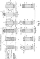
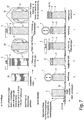
- FIG. 1 In the method steps aj the stepwise construction and the production of a road surface for the production of a road with the system technology according to the invention is shown.
- the substructure should be designed as a fine and mixed-grained soil in the subsurface.
- the proportion of fine soil particles with D ⁇ 0.06 mm is more than 15% of the dry matter.
- Such a substructure 1 would be at risk from frost and water, and therefore it is not possible on such a substructure a cover layer 10, for. As asphalt, apply.
- the substructure 1 is first torn open and loosened up to a layer depth 2 of preferably 10 cm below ground in the direction of the arrows 6, connected with an increase in volume due to the loosening.
- step c the soil stabilizing agent 3 according to the invention (abbreviation: BSM) is applied to this layer over a large area in the direction of arrow 4 and absorbed by the loosened layer.
- BSM soil stabilizing agent 3 according to the invention
- the substructure so impregnated with the soil stabilizing agent 3 in the surface area is milled and mixed in the directions of the arrows 6 to a layer depth of preferably 30 cm, so that the soil stabilizing agent is evenly distributed to the depth of 30 cm in the substrate.
- the soil stabilizing agent 3 in the direction of arrow 4 evenly on the Distributed surface, and included in the near-surface area of the soil.
- step f the entire stabilizing layer 5 impregnated with the soil stabilizing agent is again mixed and dried, whereby the introduced total amount of the soil stabilizing agent 3 is uniformly distributed to a depth of 30 cm in the substrate.
- the converted stabilizing layer 5 is now strongly compressed with a compressor 7, which results in a volume compression and results in a novel load-bearing substrate in the form of the stabilizing layer 5 now present.
- a compensating layer 8 is applied to the converted stabilizing layer 5 and sprayed in step i with the soil stabilizing agent 3 according to the invention in the direction of arrow 4 over a large area and impregnated.
- the compensation layer 8 is partially pressed into the underlying and compressed stabilization layer 5 in step j. This results in a high-strength, frost-resistant and stable base for the subsequent construction of a road surface, consisting of upper bound support layer 34 and a cover layer 10 (see the later figures).
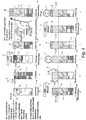
- the FIG. 2 starts from a different starting situation, where it is assumed that, starting from a substructure 1 with less than 15% by mass of fines with D ⁇ 0.06 mm, then in process step b an order of brought mineral soil with a high proportion of fines (eg clay, loam ) hereinafter referred to as clay layer 9, takes place on the substructure.
- a high proportion of fines eg clay, loam
- this layer of clay 9 with the inventive Soil stabilizer 3 sprayed in the direction of arrow 4 over a large area, so that the soil stabilizing agent 3 penetrates into the loose layer.
- step d the milling and mixing is carried out to a depth of 30 cm in the direction of arrows 6, whereby a coherent uniform and homogeneous stabilizing layer 5 is produced.
- the stabilization layer 5 is treated again in step e with the soil stabilizer 3 and in step f in the arrow directions 6 again mixed and dried.
- step g the compression and compression of the impregnated with the soil stabilizing agent stabilizing layer 3 via the compressor 7, and in step h, a leveling layer 8 is applied, which is in turn sprayed in step i with the soil stabilizer 3 in the direction of arrow 4 over a large area.
- the compensating layer 8 is then compacted with the compressor 7, thereby producing a composite with the compacted stabilizing layer 5.
- an upper bound support layer 34 and a cover layer 10, which corresponds to a conventional road surface, are applied to the stabilization layer 5 thus produced with a leveling layer 8 thereon.
- the embodiment differs according to FIG. 3 from the previous embodiments according to FIG. 1 and 2 only by being in the FIG. 3
- a road with the top edge 32 and a cover layer 10 said cover layer 10 may be made of asphalt or concrete.
- This cover layer 10 is damaged, and it must be made from this damaged road a new road with the substructure according to the invention.
- the existing damaged covering layer 10 and the supporting layer 11 are first of all torn open in the direction of the arrow 6 and mixed with the substrate 1 in method step b.
- the layer depth 2 is given here, for example, at 30 cm below the upper edge 32 of the old cover layer.
- the soil stabilizing agent 3 is then applied over a large area in the direction of arrow 4 to the thus mixed and homogenized layer, which is absorbed in the surface area of the loosened soil.
- the stabilization layer 5 is milled and mixed in the directions of the arrows 6, whereby the soil stabilizer is uniformly distributed in the layer.
- step e the soil stabilizing agent 3 is once again applied over a large area to the stabilization layer 5 prepared in this way in the direction of arrow 4, and in method step f a mixing and simultaneous drying of the stabilizing layer 5 thus homogenized and saturated with the soil stabilizing agent takes place.
- method step g a compression is now carried out with the compressor 7, and in method step h an order is made for a leveling layer 8.
- step i a renewed order of a Soil stabilizer 3 in the direction of arrow 4 on the leveling layer 8, for sealing the surface.
- method step j a compression of the leveling layer 8 and partial impressions in the stabilization layer 5 is effected with the compressor 7 and the now ready prepared substructure is covered in method step k with a conventional upper bound support layer and a cover layer of asphalt or concrete or the like. This creates a new road with a high-strength, frost-proof and stable base.
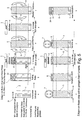
- the high water permeability of the substrate present in this example makes it possible to distribute the soil stabilizing agent 3 evenly without mechanical mixing in the lower region of the stabilizing layer 5.
- step b first a loosening of the surface with a ripper 14, which in the direction of arrow 15 along the surface of the substructure up to a layer depth 13 of z. B. 5 cm below the top edge 31 moves.
- step c the soil stabilizing agent 3 according to the invention is sprayed onto the loosened surface in the direction of arrow 4. It penetrates by the action of gravity in the direction of arrow 17 in the substructure 1 with the stones and soaked him in step d uniformly, without destroying the dense structure in the underground.
- a suitable soil is obtained from a side extraction and passed through a sieve 19 with a mesh width of 50 mm in the direction of arrow 18, wherein the stones 12 are retained with D> 50 mm and subsequently must not be crushed.
- the sieve leaves only the soil portions with a diameter of ⁇ 50 mm.
- the screen passage 20 with D ⁇ 50 mm is poured in step f in the direction of arrow 21 on the previously loosened and treated with the soil stabilizer existing Planum and distributed in a uniform layer thickness.
- the heaped up layer is impregnated with the soil stabilizing agent 3 according to the invention in the direction of arrow 4, wherein the soil stabilizing agent is taken up by the soil pores in the upper region of the filling.
- this layered layer 22 saturated with the soil stabilizer is mixed and dried and compacted with the compressor 7 in method step i.
- a compensation layer 8 is then applied, which is further impregnated in method step k with the soil stabilizing agent 3 according to the invention in the direction of arrow 4 and impregnated.
- the layers 8 + 22 + 5 thus prepared and impregnated with the soil stabilizing agent 3 are compacted with a compactor 7, whereby a frost-proof and heavy-duty substructure for applying an upper supporting layer 34, e.g. Asphalttrag für, and a cover layer 10, z. As asphalt or concrete, is given.
- a build-up layer 23 is applied with a low fines content.
- This build-up layer preferably has particles with a diameter D ⁇ 0.06 mm and ⁇ 15% by mass fraction, for the reduction of the soil present in the subsurface with a very high fines content.
- the structural layer impregnated with the soil stabilizing agent is mixed into the substrate to the depth 2 and the entire stabilizing layer is mixed 5 is mixed and crushed.
- step e a repeated application of the soil stabilizing agent 3 in the direction of arrow 4 takes place on the loosened surface.
- the stabilizing layer 5 is again mixed and dried, so that the total amount of soil stabilizing agent is uniformly distributed in the stabilizing layer, and compressed in step g with the compressor 7.
- a compensating layer 8 is applied and, in method step i, again soaked with the soil stabilizing agent 3 in the direction of arrow 4 and impregnated.
- step j the structure thus produced is again compacted with the compressor 7, so that the leveling layer is partially pressed into the previously compacted stabilization layer, and finally, in method step k, the leveling layer 8, which now firmly and homogeneously the stabilizing layer 5 is connected, a conventional upper bound support layer 34, for example as an asphalt base course, and a cover layer 10, for. As asphalt or concrete, applied.
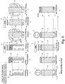
- the embodiment according to FIG. 6 differs from the aforementioned embodiments according to the FIGS. 1 to 5 merely by additionally adding recycled material to the surface of the existing substrate 1.
- a recycled material may, for. B. unloaded rubble, filter ash, broken brick, concrete break or field stones.
- a frost-prone substructure 1 is assumed, as it is also indicated as a starting point in the aforementioned exemplary embodiments.
- step b an order of the recycled material 24, which may also include stones 12, broken brick, concrete break and field stones if necessary.
- step c a first application of the soil stabilizing agent 3 in the direction of arrow 4 is caused on the layer of recycled material 24, wherein the soil stabilizing agent penetrates in the arrow directions 7 in the applied loose layer and thus produces a homogeneous stabilizing layer 5 in step d if this stabilizing layer milled and mixed.
- a soil stabilizing agent 3 in the direction of arrow 4 is applied to the stabilizing layer 5 homogenized in this way, and in process step f, in turn, this layer impregnated with the soil stabilizing agent is mixed and dried.
- step g the compression is carried out with the compressor 7, and then in step h, a compensation layer 8 is applied.
- step i for the third time the soil stabilizing agent 3 is applied to the leveling layer 8, soaking the leveling layer 8 and sealing the surface.
- the stabilization layer 5 and the leveling layer 8 are densified, so that in method step k a standard upper bound support layer 34, e.g. As asphalt base course, and a cover layer 10, z. B. can be applied from asphalt or concrete.
- a standard upper bound support layer 34 e.g. As asphalt base course, and a cover layer 10, z. B. can be applied from asphalt or concrete.
- the embodiment according to FIG. 7 assumes that the entire floor is being made for a new substructure in a bulk storage facility. It is therefore a fine and mixed-grained frost-prone soil, which is delivered to a bulk storage or in a warehouse.
- the proportion of the fine soil particles D ⁇ 0.06 mm is preferably in a proportion of> 15% of the dry matter.
- Such a floor as a proposed substructure for a road would be severely endangered by frost and water and therefore unsuitable.
- step b a first application of the soil stabilizing agent 3 is caused on the delivery floor spread for processing and in process step c, the soil is milled and mixed.
- a second order of the soil stabilizing agent 3 followed by repeated mixing in step e, and the thus homogenized soil for a later stabilization layer 5 is carried out in a protected atmosphere, the z. B. with a cover 27, as protection against precipitation and moisture is stored until further processing.
- a prepared for installation as a stabilization layer 5 soil with optimum water content for the compaction is kept in a warehouse, for example, which can then be used as needed to build a road. This takes place in method step f, where on a Underground 28 a layered installation of the stabilizing layer 5 takes place after the process step e.
- the dumping height of the installation corresponds to the depth of action of the compressor 7 used in method step g. It is assumed that the compressor 7 has such a depth of action that the compaction of the stabilization layer 5 also takes place in the substrate 28 in method step g.
- a compensation layer 8 is applied to the thus homogenized stabilization layer 5 which has been compacted, and in method step i the third application of the soil stabilization agent 3 to the compensation layer 8 takes place.
- method step j the material is compacted and in method step k, a conventional upper bound support layer 34 and a cover layer 10 made of asphalt or concrete can be applied to the thus compacted structure 5, 8.
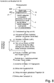
- FIG. 8 Below a covering layer 10 and upper bound support layer 34 is a leveling layer 8 is arranged, and the upcoming soil of the substrate, which has been repeatedly impregnated and mixed with the soil stabilizing agent 3 and has been converted to a stabilizing layer 5, stored on a substrate 1, which is present at the construction site.
- This substrate 1 may consist of naturally stored loose rock and is usually sensitive to frost. Due to the measures according to the invention, this existing substrate 1 is converted from the existing surface to the working depth of the milling machine into an impregnated stabilizing layer 5 and is therefore highly load-bearing and protected against the influence of frost and water.
- process step (1) a top soil removal takes place
- process step (2) a loosening of Substrate and crushing and mixing with a tiller takes place.
- step (3) the rough planum is prepared, and in step (4), a mixture of water and the soil stabilizer 3 (BSM) according to the invention is introduced according to the manufacturer's instructions and mixed intensively with the soil.
- This soil tilling are preferably used.
- the introduction of the soil stabilizing agent can happen several times after the process steps (4a) and (4b), wherein preferably at least two operations take place.
- process step (5) a fine planum is produced on the surface of this layer.
- this provided as a stabilizing layer 5 soil layer has the optimum water content, to subsequently ensure optimum compaction. If the current water content is higher than the required optimum water content for the compaction, the soil must be dried. If the actual water content is lower than the required optimum water content for the compaction, the soil should be moistened.
- step (7) compression takes place, preferably with a roller (compressor 7), this compressor preferably being intended to have more than 15 t dead weight. This ensures intensive compaction of the stabilization layer 5.
- a compensation layer 8 is installed.
- the upper bound support layer 34 eg as an asphalt base layer
- the cover layer 10 for example, installed as an asphalt surface layer, and the road is so manufactured with the operations described above.
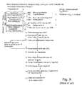
- FIG. 9 In comparison shows the FIG. 9 a conventional construction process and a construction of a conventional road.
- a conventional prior art road consists of a top layer and two underlying base layers, namely an upper bound support layer (OTS) and a lower unbound support layer (UTS), the lower support layer being the preferred is designed as an antifreeze layer.
- OTS upper bound support layer
- UTS lower unbound support layer
- FIG. 9 it is off FIG. 9 recognizable that the existing subsurface is optionally repeatedly subjected to soil consolidation, combined with the incorporation of geotextile and / or geogrid to increase bearing capacity.
- the method steps (1) to (11) show the production of the road structure according to FIG. 9 According to the state of the art.
- the higher effort compared to the method FIG. 8 lies in the fact that an improvement of the underground must take place with conventional stabilization procedures (eg lime stabilization or cement stabilization, that additional components (geotextile, geogrid) are required, but above all: that dredged poorly viable soil of the underground dredged and transported away and thus must be replaced by costly expensive frost-resistant rock mixtures, which must be installed, leveled and compacted as a lower base course.
- conventional stabilization procedures eg lime stabilization or cement stabilization, that additional components (geotextile, geogrid
- step (10) the installation of an upper bonded support layer 34, for example, as an asphalt base course
- step (11) the installation of a cover layer 10, for example as an asphalt surface layer done.
- the comparison of the procedure according to FIG. 9 with the procedure after FIG. 8 shows the advantages of the present invention.
- the present invention dispenses with the multilayer structure of a substructure by delivered frost-resistant rock mixtures as a substitute for removing soil of the substrate, because with the multiple introduction of soil stabilizer in the existing substrate and by repeated mixing and subsequent compaction, a homogeneous stabilizing layer is produced and therefore to a multilayer structure according to FIG. 9 (Prior art) can be dispensed with.
Landscapes
- Engineering & Computer Science (AREA)
- Structural Engineering (AREA)
- Life Sciences & Earth Sciences (AREA)
- General Life Sciences & Earth Sciences (AREA)
- Soil Sciences (AREA)
- Environmental & Geological Engineering (AREA)
- Agronomy & Crop Science (AREA)
- Mining & Mineral Resources (AREA)
- Paleontology (AREA)
- Civil Engineering (AREA)
- General Engineering & Computer Science (AREA)
- Road Paving Structures (AREA)
- Investigation Of Foundation Soil And Reinforcement Of Foundation Soil By Compacting Or Drainage (AREA)
- Processing Of Solid Wastes (AREA)
Priority Applications (1)
| Application Number | Priority Date | Filing Date | Title |
|---|---|---|---|
| PL15720257T PL3134581T3 (pl) | 2014-04-05 | 2015-03-28 | Sposób i środek do stabilizacji gruntu |
Applications Claiming Priority (2)
| Application Number | Priority Date | Filing Date | Title |
|---|---|---|---|
| DE102014004936.1A DE102014004936A1 (de) | 2014-04-05 | 2014-04-05 | Verfahren und Bodenstabilisierungsmittel zur dauerhaften Bodenverfestigung von frostgefährdeten fein- und gemischtkörnigen Mineralböden zur Verwendung als hochtragfähige und frostsichere Gründungs-, Trag-, Bettungs- und Verfüllschichten im Hochbau, im Str |
| PCT/EP2015/000669 WO2015149924A1 (de) | 2014-04-05 | 2015-03-28 | Verfahren und bodenstabilisierungsmittel zur dauerhaften bodenverfestigung von frostgefährdeten fein- und gemischtkörnigen mineralböden zur verwendung als hochtragfähige und frostsichere gründungs-, trag-, bettungs- und verfüllschichten im hochbau, im strassen- und wegebau und im erd- und tiefbau |
Publications (2)
| Publication Number | Publication Date |
|---|---|
| EP3134581A1 EP3134581A1 (de) | 2017-03-01 |
| EP3134581B1 true EP3134581B1 (de) | 2018-05-16 |
Family
ID=53051781
Family Applications (1)
| Application Number | Title | Priority Date | Filing Date |
|---|---|---|---|
| EP15720257.3A Active EP3134581B1 (de) | 2014-04-05 | 2015-03-28 | Verfahren und bodenstabilisierungsmittel |
Country Status (6)
| Country | Link |
|---|---|
| EP (1) | EP3134581B1 (pl) |
| BR (1) | BR112016023075B1 (pl) |
| DE (1) | DE102014004936A1 (pl) |
| ES (1) | ES2683863T3 (pl) |
| PL (1) | PL3134581T3 (pl) |
| WO (1) | WO2015149924A1 (pl) |
Families Citing this family (1)
| Publication number | Priority date | Publication date | Assignee | Title |
|---|---|---|---|---|
| CN118447957B (zh) * | 2024-05-17 | 2024-11-15 | 河海大学 | 一种高含水率淤泥固化压实土的固化参数优化方法及系统 |
Family Cites Families (9)
| Publication number | Priority date | Publication date | Assignee | Title |
|---|---|---|---|---|
| IT1066017B (it) | 1975-07-28 | 1985-03-04 | Latta Laurence Jr | Stabilizzatore per terreno e procedimento di stabilizzazione |
| JPS59188782U (ja) * | 1983-06-02 | 1984-12-14 | 福山ゴム工業株式会社 | ゴムクロ−ラ |
| CH664405A5 (de) * | 1983-09-01 | 1988-02-29 | Plana Eng Ag | Verfahren zur stabilisierung einer bodenschicht. |
| DE4428269A1 (de) | 1994-08-10 | 1996-02-15 | Henkel Kgaa | Verwendung ausgewählter und biologisch verträglicher Stabilisatoren in Polyvinylester-basierten Imprägniermitteln zur Erdreichverfestigung |
| DE19509085B4 (de) | 1995-03-16 | 2004-05-19 | Henkel Teroson Gmbh | Plastisol-Zusammensetzung, ihre Herstellung und Verwendung |
| CN1155537C (zh) * | 2002-02-06 | 2004-06-30 | 中国科学院广州地球化学研究所 | 一种粘土矿物钝化剂及制备方法和用途 |
| WO2004112953A2 (de) * | 2003-06-26 | 2004-12-29 | Silver Cay Worldwide Corp. | Verfahren zur bodenverbesserung, verwendung von polyelektrolyten dafür sowie verfahren zur behandlung eines gemenges, verfahren und vorrichtung zum herstellen eines additivs dafür |
| WO2005121277A1 (de) * | 2004-06-08 | 2005-12-22 | Christoph Muther | Verfahren zur behandlung eines gemenges sowie verfahren und vorrichtung zum herstellen eines additivs dafür |
| CN102079980A (zh) * | 2009-11-26 | 2011-06-01 | 钟维安 | 膨胀土改良剂 |
-
2014
- 2014-04-05 DE DE102014004936.1A patent/DE102014004936A1/de not_active Withdrawn
-
2015
- 2015-03-28 EP EP15720257.3A patent/EP3134581B1/de active Active
- 2015-03-28 WO PCT/EP2015/000669 patent/WO2015149924A1/de not_active Ceased
- 2015-03-28 ES ES15720257.3T patent/ES2683863T3/es active Active
- 2015-03-28 PL PL15720257T patent/PL3134581T3/pl unknown
- 2015-03-28 BR BR112016023075-2A patent/BR112016023075B1/pt active IP Right Grant
Non-Patent Citations (1)
| Title |
|---|
| None * |
Also Published As
| Publication number | Publication date |
|---|---|
| EP3134581A1 (de) | 2017-03-01 |
| ES2683863T3 (es) | 2018-09-28 |
| PL3134581T3 (pl) | 2018-11-30 |
| BR112016023075B1 (pt) | 2022-02-15 |
| WO2015149924A1 (de) | 2015-10-08 |
| BR112016023075A2 (pl) | 2017-08-15 |
| DE102014004936A1 (de) | 2015-10-08 |
Similar Documents
| Publication | Publication Date | Title |
|---|---|---|
| DE3210072C2 (de) | Injektionsmittel für die Verbesserung der strukturellen Festigkeit von weichem organische Stoffe enthaltendem Boden | |
| EP0404999B1 (de) | Verfahren zur Herstellung einer Abdichtung bei Deponien oder dergleichen | |
| DE102008016325A1 (de) | Boden- oder Fundamentverfestiger | |
| EP1992425B1 (de) | Verfahren zur Wiederverwertung von kunststoffhaltigem Abfall | |
| DE2727077C2 (de) | Verfahren zur Herstellung einer flüssigkeitsdichten Sperrschicht als Auskleidung einer Grube für eine Mülldeponie od.dgl. | |
| DE69923310T2 (de) | Verfahren zur bodenstabilisierung für strassenbauarbeiten | |
| DE10302772A1 (de) | Baustoff und Verfahren zu seiner Herstellung | |
| EP3134581B1 (de) | Verfahren und bodenstabilisierungsmittel | |
| EP0456035A2 (de) | Fahrbahndecke für Verkehrsflächen | |
| DE3127350C2 (de) | Verfahren zur Bodenverfestigung | |
| Dronamraju | Studies on field stabilization methods to prevent surficial slope failures of earthfill dams | |
| EP1655410B1 (de) | Verfahren zur Herstellung einer Tragschicht | |
| DE102007056408B4 (de) | System und Verfahren zum Aufbau einer Fahrbahn | |
| DE9215913U1 (de) | Deponie und Asphaltdichtung hierfür | |
| DE102022104302A1 (de) | Bodenverfestigungsmittel und Verfahren zur Untergrundbefestigung | |
| EP3877351B1 (de) | Verwendung von mineralschaum zur haldenabdeckung | |
| DD245001A1 (de) | Verfahren zur herstellung von gewaessergrundabdichtungen | |
| EP1213393B1 (de) | Verfahren zur Verstärkung bzw. Bewehrung von mineralischen Gemischen, insbesondere von Erdstoffsystemen unter Verwendung fasriger Materialien | |
| WO2005121277A1 (de) | Verfahren zur behandlung eines gemenges sowie verfahren und vorrichtung zum herstellen eines additivs dafür | |
| EP3366843B1 (de) | Polymermodifizierte bodenstabilisierung | |
| EP1020415B1 (de) | Verfahren zum Verfestigen schadstoffhaltiger, kontaminierter staubförmiger bis grobkörniger Anfallstoffe | |
| ABDULLAHI | STABILIZATION OF CLAYEY SOIL USING CEMENT AND VOLCANIC ASH FOR SUSTAINABLE ROAD CONSTRUCTION | |
| DE19928397B4 (de) | Verfahren zur Bodenstabilisierung von rolligen, locker gelagerten, gewachsenen Böden, geschütteten Erdmassen und wassergesättigten Böden | |
| AT504701B1 (de) | Oberflächenabdichtung für abfalldeponien | |
| DE10352434B4 (de) | Anordnung zur Oberflächenabdeckung von nicht tragfähigen, auch umweltproblematischen Ablagerungen |
Legal Events
| Date | Code | Title | Description |
|---|---|---|---|
| STAA | Information on the status of an ep patent application or granted ep patent |
Free format text: STATUS: THE INTERNATIONAL PUBLICATION HAS BEEN MADE |
|
| PUAI | Public reference made under article 153(3) epc to a published international application that has entered the european phase |
Free format text: ORIGINAL CODE: 0009012 |
|
| STAA | Information on the status of an ep patent application or granted ep patent |
Free format text: STATUS: REQUEST FOR EXAMINATION WAS MADE |
|
| 17P | Request for examination filed |
Effective date: 20170113 |
|
| AK | Designated contracting states |
Kind code of ref document: A1 Designated state(s): AL AT BE BG CH CY CZ DE DK EE ES FI FR GB GR HR HU IE IS IT LI LT LU LV MC MK MT NL NO PL PT RO RS SE SI SK SM TR |
|
| AX | Request for extension of the european patent |
Extension state: BA ME |
|
| DAV | Request for validation of the european patent (deleted) | ||
| DAX | Request for extension of the european patent (deleted) | ||
| GRAP | Despatch of communication of intention to grant a patent |
Free format text: ORIGINAL CODE: EPIDOSNIGR1 |
|
| STAA | Information on the status of an ep patent application or granted ep patent |
Free format text: STATUS: GRANT OF PATENT IS INTENDED |
|
| INTG | Intention to grant announced |
Effective date: 20180104 |
|
| GRAS | Grant fee paid |
Free format text: ORIGINAL CODE: EPIDOSNIGR3 |
|
| GRAA | (expected) grant |
Free format text: ORIGINAL CODE: 0009210 |
|
| STAA | Information on the status of an ep patent application or granted ep patent |
Free format text: STATUS: THE PATENT HAS BEEN GRANTED |
|
| AK | Designated contracting states |
Kind code of ref document: B1 Designated state(s): AL AT BE BG CH CY CZ DE DK EE ES FI FR GB GR HR HU IE IS IT LI LT LU LV MC MK MT NL NO PL PT RO RS SE SI SK SM TR |
|
| REG | Reference to a national code |
Ref country code: GB Ref legal event code: FG4D Free format text: NOT ENGLISH |
|
| REG | Reference to a national code |
Ref country code: CH Ref legal event code: EP |
|
| REG | Reference to a national code |
Ref country code: IE Ref legal event code: FG4D Free format text: LANGUAGE OF EP DOCUMENT: GERMAN |
|
| REG | Reference to a national code |
Ref country code: DE Ref legal event code: R096 Ref document number: 502015004306 Country of ref document: DE |
|
| REG | Reference to a national code |
Ref country code: AT Ref legal event code: REF Ref document number: 999688 Country of ref document: AT Kind code of ref document: T Effective date: 20180615 |
|
| REG | Reference to a national code |
Ref country code: RO Ref legal event code: EPE |
|
| REG | Reference to a national code |
Ref country code: CH Ref legal event code: NV Representative=s name: LUCHS AND PARTNER AG PATENTANWAELTE, CH |
|
| REG | Reference to a national code |
Ref country code: NL Ref legal event code: MP Effective date: 20180516 |
|
| REG | Reference to a national code |
Ref country code: ES Ref legal event code: FG2A Ref document number: 2683863 Country of ref document: ES Kind code of ref document: T3 Effective date: 20180928 |
|
| REG | Reference to a national code |
Ref country code: LT Ref legal event code: MG4D |
|
| REG | Reference to a national code |
Ref country code: NO Ref legal event code: T2 Effective date: 20180516 |
|
| PG25 | Lapsed in a contracting state [announced via postgrant information from national office to epo] |
Ref country code: BG Free format text: LAPSE BECAUSE OF FAILURE TO SUBMIT A TRANSLATION OF THE DESCRIPTION OR TO PAY THE FEE WITHIN THE PRESCRIBED TIME-LIMIT Effective date: 20180816 Ref country code: LT Free format text: LAPSE BECAUSE OF FAILURE TO SUBMIT A TRANSLATION OF THE DESCRIPTION OR TO PAY THE FEE WITHIN THE PRESCRIBED TIME-LIMIT Effective date: 20180516 Ref country code: SE Free format text: LAPSE BECAUSE OF FAILURE TO SUBMIT A TRANSLATION OF THE DESCRIPTION OR TO PAY THE FEE WITHIN THE PRESCRIBED TIME-LIMIT Effective date: 20180516 Ref country code: FI Free format text: LAPSE BECAUSE OF FAILURE TO SUBMIT A TRANSLATION OF THE DESCRIPTION OR TO PAY THE FEE WITHIN THE PRESCRIBED TIME-LIMIT Effective date: 20180516 |
|
| PG25 | Lapsed in a contracting state [announced via postgrant information from national office to epo] |
Ref country code: NL Free format text: LAPSE BECAUSE OF FAILURE TO SUBMIT A TRANSLATION OF THE DESCRIPTION OR TO PAY THE FEE WITHIN THE PRESCRIBED TIME-LIMIT Effective date: 20180516 Ref country code: LV Free format text: LAPSE BECAUSE OF FAILURE TO SUBMIT A TRANSLATION OF THE DESCRIPTION OR TO PAY THE FEE WITHIN THE PRESCRIBED TIME-LIMIT Effective date: 20180516 Ref country code: HR Free format text: LAPSE BECAUSE OF FAILURE TO SUBMIT A TRANSLATION OF THE DESCRIPTION OR TO PAY THE FEE WITHIN THE PRESCRIBED TIME-LIMIT Effective date: 20180516 Ref country code: RS Free format text: LAPSE BECAUSE OF FAILURE TO SUBMIT A TRANSLATION OF THE DESCRIPTION OR TO PAY THE FEE WITHIN THE PRESCRIBED TIME-LIMIT Effective date: 20180516 Ref country code: GR Free format text: LAPSE BECAUSE OF FAILURE TO SUBMIT A TRANSLATION OF THE DESCRIPTION OR TO PAY THE FEE WITHIN THE PRESCRIBED TIME-LIMIT Effective date: 20180817 |
|
| PG25 | Lapsed in a contracting state [announced via postgrant information from national office to epo] |
Ref country code: EE Free format text: LAPSE BECAUSE OF FAILURE TO SUBMIT A TRANSLATION OF THE DESCRIPTION OR TO PAY THE FEE WITHIN THE PRESCRIBED TIME-LIMIT Effective date: 20180516 Ref country code: DK Free format text: LAPSE BECAUSE OF FAILURE TO SUBMIT A TRANSLATION OF THE DESCRIPTION OR TO PAY THE FEE WITHIN THE PRESCRIBED TIME-LIMIT Effective date: 20180516 Ref country code: SK Free format text: LAPSE BECAUSE OF FAILURE TO SUBMIT A TRANSLATION OF THE DESCRIPTION OR TO PAY THE FEE WITHIN THE PRESCRIBED TIME-LIMIT Effective date: 20180516 Ref country code: CZ Free format text: LAPSE BECAUSE OF FAILURE TO SUBMIT A TRANSLATION OF THE DESCRIPTION OR TO PAY THE FEE WITHIN THE PRESCRIBED TIME-LIMIT Effective date: 20180516 |
|
| REG | Reference to a national code |
Ref country code: DE Ref legal event code: R097 Ref document number: 502015004306 Country of ref document: DE |
|
| PG25 | Lapsed in a contracting state [announced via postgrant information from national office to epo] |
Ref country code: SM Free format text: LAPSE BECAUSE OF FAILURE TO SUBMIT A TRANSLATION OF THE DESCRIPTION OR TO PAY THE FEE WITHIN THE PRESCRIBED TIME-LIMIT Effective date: 20180516 Ref country code: IT Free format text: LAPSE BECAUSE OF FAILURE TO SUBMIT A TRANSLATION OF THE DESCRIPTION OR TO PAY THE FEE WITHIN THE PRESCRIBED TIME-LIMIT Effective date: 20180516 |
|
| PLBE | No opposition filed within time limit |
Free format text: ORIGINAL CODE: 0009261 |
|
| STAA | Information on the status of an ep patent application or granted ep patent |
Free format text: STATUS: NO OPPOSITION FILED WITHIN TIME LIMIT |
|
| 26N | No opposition filed |
Effective date: 20190219 |
|
| PG25 | Lapsed in a contracting state [announced via postgrant information from national office to epo] |
Ref country code: SI Free format text: LAPSE BECAUSE OF FAILURE TO SUBMIT A TRANSLATION OF THE DESCRIPTION OR TO PAY THE FEE WITHIN THE PRESCRIBED TIME-LIMIT Effective date: 20180516 |
|
| PG25 | Lapsed in a contracting state [announced via postgrant information from national office to epo] |
Ref country code: MC Free format text: LAPSE BECAUSE OF FAILURE TO SUBMIT A TRANSLATION OF THE DESCRIPTION OR TO PAY THE FEE WITHIN THE PRESCRIBED TIME-LIMIT Effective date: 20180516 |
|
| PG25 | Lapsed in a contracting state [announced via postgrant information from national office to epo] |
Ref country code: LU Free format text: LAPSE BECAUSE OF NON-PAYMENT OF DUE FEES Effective date: 20190328 Ref country code: AL Free format text: LAPSE BECAUSE OF FAILURE TO SUBMIT A TRANSLATION OF THE DESCRIPTION OR TO PAY THE FEE WITHIN THE PRESCRIBED TIME-LIMIT Effective date: 20180516 |
|
| PG25 | Lapsed in a contracting state [announced via postgrant information from national office to epo] |
Ref country code: MT Free format text: LAPSE BECAUSE OF FAILURE TO SUBMIT A TRANSLATION OF THE DESCRIPTION OR TO PAY THE FEE WITHIN THE PRESCRIBED TIME-LIMIT Effective date: 20180516 Ref country code: PT Free format text: LAPSE BECAUSE OF FAILURE TO SUBMIT A TRANSLATION OF THE DESCRIPTION OR TO PAY THE FEE WITHIN THE PRESCRIBED TIME-LIMIT Effective date: 20180917 |
|
| PGFP | Annual fee paid to national office [announced via postgrant information from national office to epo] |
Ref country code: TR Payment date: 20200325 Year of fee payment: 6 |
|
| PG25 | Lapsed in a contracting state [announced via postgrant information from national office to epo] |
Ref country code: CY Free format text: LAPSE BECAUSE OF FAILURE TO SUBMIT A TRANSLATION OF THE DESCRIPTION OR TO PAY THE FEE WITHIN THE PRESCRIBED TIME-LIMIT Effective date: 20180516 |
|
| PG25 | Lapsed in a contracting state [announced via postgrant information from national office to epo] |
Ref country code: IS Free format text: LAPSE BECAUSE OF FAILURE TO SUBMIT A TRANSLATION OF THE DESCRIPTION OR TO PAY THE FEE WITHIN THE PRESCRIBED TIME-LIMIT Effective date: 20180916 |
|
| PG25 | Lapsed in a contracting state [announced via postgrant information from national office to epo] |
Ref country code: HU Free format text: LAPSE BECAUSE OF FAILURE TO SUBMIT A TRANSLATION OF THE DESCRIPTION OR TO PAY THE FEE WITHIN THE PRESCRIBED TIME-LIMIT; INVALID AB INITIO Effective date: 20150328 |
|
| PG25 | Lapsed in a contracting state [announced via postgrant information from national office to epo] |
Ref country code: MK Free format text: LAPSE BECAUSE OF FAILURE TO SUBMIT A TRANSLATION OF THE DESCRIPTION OR TO PAY THE FEE WITHIN THE PRESCRIBED TIME-LIMIT Effective date: 20180516 |
|
| PGFP | Annual fee paid to national office [announced via postgrant information from national office to epo] |
Ref country code: IE Payment date: 20230920 Year of fee payment: 9 Ref country code: AT Payment date: 20230921 Year of fee payment: 9 |
|
| REG | Reference to a national code |
Ref country code: AT Ref legal event code: MM01 Ref document number: 999688 Country of ref document: AT Kind code of ref document: T Effective date: 20240328 |
|
| PG25 | Lapsed in a contracting state [announced via postgrant information from national office to epo] |
Ref country code: AT Free format text: LAPSE BECAUSE OF NON-PAYMENT OF DUE FEES Effective date: 20240328 |
|
| PG25 | Lapsed in a contracting state [announced via postgrant information from national office to epo] |
Ref country code: IE Free format text: LAPSE BECAUSE OF NON-PAYMENT OF DUE FEES Effective date: 20240328 |
|
| PG25 | Lapsed in a contracting state [announced via postgrant information from national office to epo] |
Ref country code: IE Free format text: LAPSE BECAUSE OF NON-PAYMENT OF DUE FEES Effective date: 20240328 Ref country code: AT Free format text: LAPSE BECAUSE OF NON-PAYMENT OF DUE FEES Effective date: 20240328 |
|
| PGFP | Annual fee paid to national office [announced via postgrant information from national office to epo] |
Ref country code: ES Payment date: 20250917 Year of fee payment: 11 |
|
| PGFP | Annual fee paid to national office [announced via postgrant information from national office to epo] |
Ref country code: DE Payment date: 20250919 Year of fee payment: 11 |
|
| PGFP | Annual fee paid to national office [announced via postgrant information from national office to epo] |
Ref country code: NO Payment date: 20250919 Year of fee payment: 11 |
|
| PGFP | Annual fee paid to national office [announced via postgrant information from national office to epo] |
Ref country code: PL Payment date: 20250915 Year of fee payment: 11 |
|
| PGFP | Annual fee paid to national office [announced via postgrant information from national office to epo] |
Ref country code: BE Payment date: 20250919 Year of fee payment: 11 Ref country code: GB Payment date: 20250916 Year of fee payment: 11 |
|
| PGFP | Annual fee paid to national office [announced via postgrant information from national office to epo] |
Ref country code: FR Payment date: 20250924 Year of fee payment: 11 |
|
| PGFP | Annual fee paid to national office [announced via postgrant information from national office to epo] |
Ref country code: CH Payment date: 20250916 Year of fee payment: 11 |
|
| PGFP | Annual fee paid to national office [announced via postgrant information from national office to epo] |
Ref country code: RO Payment date: 20250918 Year of fee payment: 11 |