EP3134581B1 - Method and soil-stabilizing means - Google Patents
Method and soil-stabilizing means Download PDFInfo
- Publication number
- EP3134581B1 EP3134581B1 EP15720257.3A EP15720257A EP3134581B1 EP 3134581 B1 EP3134581 B1 EP 3134581B1 EP 15720257 A EP15720257 A EP 15720257A EP 3134581 B1 EP3134581 B1 EP 3134581B1
- Authority
- EP
- European Patent Office
- Prior art keywords
- soil
- layer
- der
- water
- stabilising
- Prior art date
- Legal status (The legal status is an assumption and is not a legal conclusion. Google has not performed a legal analysis and makes no representation as to the accuracy of the status listed.)
- Active
Links
- 238000000034 method Methods 0.000 title claims description 94
- 239000002689 soil Substances 0.000 claims description 198
- XLYOFNOQVPJJNP-UHFFFAOYSA-N water Substances O XLYOFNOQVPJJNP-UHFFFAOYSA-N 0.000 claims description 135
- 239000002245 particle Substances 0.000 claims description 50
- 238000010276 construction Methods 0.000 claims description 40
- 239000000203 mixture Substances 0.000 claims description 26
- 230000006641 stabilisation Effects 0.000 claims description 25
- 229910052500 inorganic mineral Inorganic materials 0.000 claims description 17
- 239000011707 mineral Substances 0.000 claims description 17
- 230000009467 reduction Effects 0.000 claims description 14
- 239000004927 clay Substances 0.000 claims description 12
- 239000000463 material Substances 0.000 claims description 12
- 229910021645 metal ion Inorganic materials 0.000 claims description 12
- 239000011435 rock Substances 0.000 claims description 12
- 150000002500 ions Chemical class 0.000 claims description 11
- -1 hydrogen ions Chemical class 0.000 claims description 10
- 229910052739 hydrogen Inorganic materials 0.000 claims description 8
- 239000001257 hydrogen Substances 0.000 claims description 8
- 239000011148 porous material Substances 0.000 claims description 7
- 239000002253 acid Substances 0.000 claims description 6
- 238000011049 filling Methods 0.000 claims description 6
- 238000010348 incorporation Methods 0.000 claims description 6
- 239000005871 repellent Substances 0.000 claims description 6
- 230000002209 hydrophobic effect Effects 0.000 claims description 5
- 230000007246 mechanism Effects 0.000 claims description 5
- 239000000470 constituent Substances 0.000 claims description 4
- 239000007788 liquid Substances 0.000 claims description 4
- 150000007513 acids Chemical class 0.000 claims description 3
- 125000000524 functional group Chemical group 0.000 claims description 3
- 238000002791 soaking Methods 0.000 claims description 3
- 238000001179 sorption measurement Methods 0.000 claims description 3
- QAOWNCQODCNURD-UHFFFAOYSA-L sulfate group Chemical group S(=O)(=O)([O-])[O-] QAOWNCQODCNURD-UHFFFAOYSA-L 0.000 claims description 3
- 230000003019 stabilising effect Effects 0.000 claims 5
- 229910006069 SO3H Inorganic materials 0.000 claims 2
- 150000005837 radical ions Chemical class 0.000 claims 2
- 239000010410 layer Substances 0.000 description 158
- 239000003583 soil stabilizing agent Substances 0.000 description 117
- 238000005056 compaction Methods 0.000 description 33
- 230000000087 stabilizing effect Effects 0.000 description 24
- 238000011105 stabilization Methods 0.000 description 23
- 239000000758 substrate Substances 0.000 description 21
- 238000002156 mixing Methods 0.000 description 20
- SEQDDYPDSLOBDC-UHFFFAOYSA-N Temazepam Chemical compound N=1C(O)C(=O)N(C)C2=CC=C(Cl)C=C2C=1C1=CC=CC=C1 SEQDDYPDSLOBDC-UHFFFAOYSA-N 0.000 description 18
- 239000010426 asphalt Substances 0.000 description 18
- 238000005516 engineering process Methods 0.000 description 10
- 238000004519 manufacturing process Methods 0.000 description 10
- 239000004567 concrete Substances 0.000 description 9
- 239000004576 sand Substances 0.000 description 9
- GNFTZDOKVXKIBK-UHFFFAOYSA-N 3-(2-methoxyethoxy)benzohydrazide Chemical compound COCCOC1=CC=CC(C(=O)NN)=C1 GNFTZDOKVXKIBK-UHFFFAOYSA-N 0.000 description 8
- 230000008901 benefit Effects 0.000 description 8
- 230000006835 compression Effects 0.000 description 8
- 238000007906 compression Methods 0.000 description 8
- FGUUSXIOTUKUDN-IBGZPJMESA-N C1(=CC=CC=C1)N1C2=C(NC([C@H](C1)NC=1OC(=NN=1)C1=CC=CC=C1)=O)C=CC=C2 Chemical compound C1(=CC=CC=C1)N1C2=C(NC([C@H](C1)NC=1OC(=NN=1)C1=CC=CC=C1)=O)C=CC=C2 FGUUSXIOTUKUDN-IBGZPJMESA-N 0.000 description 7
- YTAHJIFKAKIKAV-XNMGPUDCSA-N [(1R)-3-morpholin-4-yl-1-phenylpropyl] N-[(3S)-2-oxo-5-phenyl-1,3-dihydro-1,4-benzodiazepin-3-yl]carbamate Chemical compound O=C1[C@H](N=C(C2=C(N1)C=CC=C2)C1=CC=CC=C1)NC(O[C@H](CCN1CCOCC1)C1=CC=CC=C1)=O YTAHJIFKAKIKAV-XNMGPUDCSA-N 0.000 description 7
- 230000009471 action Effects 0.000 description 6
- 239000000654 additive Substances 0.000 description 6
- 238000009826 distribution Methods 0.000 description 6
- 238000009434 installation Methods 0.000 description 6
- 238000005259 measurement Methods 0.000 description 6
- 239000012224 working solution Substances 0.000 description 6
- 230000000694 effects Effects 0.000 description 5
- 238000003801 milling Methods 0.000 description 5
- 230000008569 process Effects 0.000 description 5
- 230000002829 reductive effect Effects 0.000 description 5
- 239000003381 stabilizer Substances 0.000 description 5
- 238000009435 building construction Methods 0.000 description 4
- 238000007596 consolidation process Methods 0.000 description 4
- 239000003864 humus Substances 0.000 description 4
- 238000003780 insertion Methods 0.000 description 4
- 230000037431 insertion Effects 0.000 description 4
- 239000004014 plasticizer Substances 0.000 description 4
- 238000007711 solidification Methods 0.000 description 4
- 230000008023 solidification Effects 0.000 description 4
- 238000004458 analytical method Methods 0.000 description 3
- 239000003054 catalyst Substances 0.000 description 3
- 230000018044 dehydration Effects 0.000 description 3
- 238000006297 dehydration reaction Methods 0.000 description 3
- 239000010419 fine particle Substances 0.000 description 3
- 238000005470 impregnation Methods 0.000 description 3
- 230000006872 improvement Effects 0.000 description 3
- 230000002045 lasting effect Effects 0.000 description 3
- 238000007789 sealing Methods 0.000 description 3
- 238000004062 sedimentation Methods 0.000 description 3
- 210000002023 somite Anatomy 0.000 description 3
- 150000003460 sulfonic acids Chemical class 0.000 description 3
- 235000008733 Citrus aurantifolia Nutrition 0.000 description 2
- 229920001944 Plastisol Polymers 0.000 description 2
- 235000011941 Tilia x europaea Nutrition 0.000 description 2
- 239000004480 active ingredient Substances 0.000 description 2
- 230000000996 additive effect Effects 0.000 description 2
- 239000000853 adhesive Substances 0.000 description 2
- 230000001070 adhesive effect Effects 0.000 description 2
- 230000002528 anti-freeze Effects 0.000 description 2
- 238000009412 basement excavation Methods 0.000 description 2
- 239000011230 binding agent Substances 0.000 description 2
- 239000011449 brick Substances 0.000 description 2
- 239000004568 cement Substances 0.000 description 2
- 230000008859 change Effects 0.000 description 2
- 238000006243 chemical reaction Methods 0.000 description 2
- 239000003795 chemical substances by application Substances 0.000 description 2
- 238000000576 coating method Methods 0.000 description 2
- 238000010790 dilution Methods 0.000 description 2
- 239000012895 dilution Substances 0.000 description 2
- 238000001035 drying Methods 0.000 description 2
- 239000003822 epoxy resin Substances 0.000 description 2
- 230000003628 erosive effect Effects 0.000 description 2
- 150000002148 esters Chemical class 0.000 description 2
- 238000000605 extraction Methods 0.000 description 2
- 230000008014 freezing Effects 0.000 description 2
- 238000007710 freezing Methods 0.000 description 2
- 239000004746 geotextile Substances 0.000 description 2
- JEGUKCSWCFPDGT-UHFFFAOYSA-N h2o hydrate Chemical compound O.O JEGUKCSWCFPDGT-UHFFFAOYSA-N 0.000 description 2
- 230000036571 hydration Effects 0.000 description 2
- 238000006703 hydration reaction Methods 0.000 description 2
- 230000002427 irreversible effect Effects 0.000 description 2
- 239000004571 lime Substances 0.000 description 2
- 238000011068 loading method Methods 0.000 description 2
- 230000005499 meniscus Effects 0.000 description 2
- 238000006386 neutralization reaction Methods 0.000 description 2
- 239000004033 plastic Substances 0.000 description 2
- 229920003023 plastic Polymers 0.000 description 2
- 239000004999 plastisol Substances 0.000 description 2
- 229920000647 polyepoxide Polymers 0.000 description 2
- 238000002360 preparation method Methods 0.000 description 2
- 238000012545 processing Methods 0.000 description 2
- 229920006395 saturated elastomer Polymers 0.000 description 2
- 238000005029 sieve analysis Methods 0.000 description 2
- 239000007787 solid Substances 0.000 description 2
- 230000003068 static effect Effects 0.000 description 2
- 238000003860 storage Methods 0.000 description 2
- 239000002344 surface layer Substances 0.000 description 2
- 230000008961 swelling Effects 0.000 description 2
- 238000012360 testing method Methods 0.000 description 2
- 230000007704 transition Effects 0.000 description 2
- HRPVXLWXLXDGHG-UHFFFAOYSA-N Acrylamide Chemical compound NC(=O)C=C HRPVXLWXLXDGHG-UHFFFAOYSA-N 0.000 description 1
- 241001136792 Alle Species 0.000 description 1
- VTYYLEPIZMXCLO-UHFFFAOYSA-L Calcium carbonate Chemical compound [Ca+2].[O-]C([O-])=O VTYYLEPIZMXCLO-UHFFFAOYSA-L 0.000 description 1
- 206010013457 Dissociation Diseases 0.000 description 1
- 206010013786 Dry skin Diseases 0.000 description 1
- 241001295925 Gegenes Species 0.000 description 1
- 238000010521 absorption reaction Methods 0.000 description 1
- 238000013459 approach Methods 0.000 description 1
- 239000012298 atmosphere Substances 0.000 description 1
- 235000021167 banquet Nutrition 0.000 description 1
- 230000005540 biological transmission Effects 0.000 description 1
- 239000004566 building material Substances 0.000 description 1
- 239000011248 coating agent Substances 0.000 description 1
- 230000001427 coherent effect Effects 0.000 description 1
- 239000002131 composite material Substances 0.000 description 1
- 238000007796 conventional method Methods 0.000 description 1
- 229920001577 copolymer Polymers 0.000 description 1
- 239000013078 crystal Substances 0.000 description 1
- 230000001419 dependent effect Effects 0.000 description 1
- 230000008021 deposition Effects 0.000 description 1
- 238000013461 design Methods 0.000 description 1
- 238000011161 development Methods 0.000 description 1
- 238000006073 displacement reaction Methods 0.000 description 1
- 238000010494 dissociation reaction Methods 0.000 description 1
- 230000005593 dissociations Effects 0.000 description 1
- 239000000428 dust Substances 0.000 description 1
- 229920001971 elastomer Polymers 0.000 description 1
- 230000008030 elimination Effects 0.000 description 1
- 238000003379 elimination reaction Methods 0.000 description 1
- 239000000839 emulsion Substances 0.000 description 1
- 238000005265 energy consumption Methods 0.000 description 1
- 230000002349 favourable effect Effects 0.000 description 1
- 239000000945 filler Substances 0.000 description 1
- 230000005484 gravity Effects 0.000 description 1
- 238000005342 ion exchange Methods 0.000 description 1
- 238000009533 lab test Methods 0.000 description 1
- 239000008239 natural water Substances 0.000 description 1
- 239000005416 organic matter Substances 0.000 description 1
- XLYOFNOQVPJJNP-UHFFFAOYSA-O oxonium Chemical compound [OH3+] XLYOFNOQVPJJNP-UHFFFAOYSA-O 0.000 description 1
- 238000012856 packing Methods 0.000 description 1
- 230000036961 partial effect Effects 0.000 description 1
- 230000000149 penetrating effect Effects 0.000 description 1
- 230000035515 penetration Effects 0.000 description 1
- 230000035699 permeability Effects 0.000 description 1
- 229920000867 polyelectrolyte Polymers 0.000 description 1
- 229920000642 polymer Polymers 0.000 description 1
- 229920001290 polyvinyl ester Polymers 0.000 description 1
- 238000001556 precipitation Methods 0.000 description 1
- 238000005086 pumping Methods 0.000 description 1
- 238000009418 renovation Methods 0.000 description 1
- 230000002940 repellent Effects 0.000 description 1
- 230000000717 retained effect Effects 0.000 description 1
- 230000000630 rising effect Effects 0.000 description 1
- 238000005070 sampling Methods 0.000 description 1
- 238000012216 screening Methods 0.000 description 1
- 230000035945 sensitivity Effects 0.000 description 1
- 238000000926 separation method Methods 0.000 description 1
- 238000004856 soil analysis Methods 0.000 description 1
- 239000000126 substance Substances 0.000 description 1
- 238000010971 suitability test Methods 0.000 description 1
- 238000012549 training Methods 0.000 description 1
- 238000012546 transfer Methods 0.000 description 1
- 239000002699 waste material Substances 0.000 description 1
Images


Classifications
-
- E—FIXED CONSTRUCTIONS
- E02—HYDRAULIC ENGINEERING; FOUNDATIONS; SOIL SHIFTING
- E02D—FOUNDATIONS; EXCAVATIONS; EMBANKMENTS; UNDERGROUND OR UNDERWATER STRUCTURES
- E02D3/00—Improving or preserving soil or rock, e.g. preserving permafrost soil
-
- E—FIXED CONSTRUCTIONS
- E02—HYDRAULIC ENGINEERING; FOUNDATIONS; SOIL SHIFTING
- E02D—FOUNDATIONS; EXCAVATIONS; EMBANKMENTS; UNDERGROUND OR UNDERWATER STRUCTURES
- E02D3/00—Improving or preserving soil or rock, e.g. preserving permafrost soil
- E02D3/12—Consolidating by placing solidifying or pore-filling substances in the soil
- E02D3/126—Consolidating by placing solidifying or pore-filling substances in the soil and mixing by rotating blades
Definitions
- the invention relates to a system technology consisting of the process instructions and an active ingredient used for solidification, hereinafter referred to as "soil stabilizer", for use of non-construction suitable frost-prone, fine and mixed-grained mineral soils and their conversion to durable + resistant + frost-resistant + high-carrying foundation , Load-bearing, bedding and filling layers in construction.
- the DE 26 33 749 A1 describes a soil stabilizer for soil stabilization based on epoxy resin ester.
- a plasticizer Alkylsulfonester is specified. After the addition of the soil stabilizer, compaction and, in particular, curing of the epoxy resin-treated soil must be carried out to obtain a stable, consolidated soil layer.
- the DE 44 28 269 A1 describes an impregnation soil stabilizer for soil consolidation based on polyvinyl esters. This document discloses plasticizers based on alkylsulfonic acids.
- the DE 195 09 085 A1 discloses a plastisol composition. Plasticizers based on alkyl sulfonic acid esters are described, and it is stated that coatings of a general type can be made with this type of plastisol composition.
- the DE 10 2004 031 039 A1 discloses a method for soil consolidation in which several additives in the form of polyelectrolytes, preferably polymers or copolymers based on acrylamide, and a hydraulic binder or a bitumen emulsion are applied to the soil to be consolidated and mixed with the soil. This is followed by mechanical compaction of the soil.
- the invention has for its object to improve a system technology for soil stabilization, consisting of a procedure and a soil stabilizer, in terms of process flow and cost to achieve a permanent indestructible improvement in the soil properties of fine-grained and mixed-grained, cohesive soils.
- a preferred field of application of the invention is the implementation of the method and the application of the soil stabilizer as highly load-bearing and frost-resistant foundation, support, bedding and filling layers in building construction, in road and road construction and in earthworks and civil engineering.
- the application is generally valid for new buildings and also for renovations.
- a particularly favorable application of the invention relates not only to road construction, but also to building construction.
- foundations are used, which are used as foundation pads for floor slabs of buildings. If no viable layer is present in the foundation level of a building, the stabilizer according to the invention is also used for the consolidation of the substrate.
- stable backfill layers can also be produced in building construction, e.g. serve to fill up excavated excavations.
- Such stabilized filler layers are also used in pipeline construction for covering the pipelines installed in the ground.
- Existing structures can also be drained by partially excavating the soil previously installed in the excavation area and re-installing it after treatment with the soil stabilizer according to the invention.
- Another important application of the present invention is in the treatment of moats in which the sole or slopes are susceptible to erosion. Also in this case, the sole or embankments of moats can be secured and sealed against erosion by treatment with the soil stabilizer of the present invention.
- the soil stabilizer of the invention is even suitable for the production of blocks or other solid structures in a modular design.
- a soil treated with the stabilizing agent is pressed into molds and subsequently the building blocks, structural elements or other modular building elements thus produced are used for further construction in civil engineering. These elements are then particularly waterproof, highly resilient and protected against ingress of moisture.
- the use of the soil stabilizer according to the invention is also suitable for dyke construction or dyke restoration. It can both the entire structure of a dike or even water-stressed parts of a dike (such as the sealing apron) are protected against ingress of pressurized water.
- An essential feature of the soil stabilizer is that a permanent reduction of the water binding forces of the fine soil components of these soils is achieved by a soil stabilizer acting as an ion exchanger and catalyst.
- the soil stabilizer used is a slightly water-soluble, clear liquid whose chemical composition is a mixture of different sulfonic acids + special additives + water.
- the viscosity is oily.
- a major constituent of the active ingredients of the soil stabilizer is a mixture of various sulfonic acids which share the common functional group -SO 3 H linked to a water repellent organic component R.
- the representation is: R - SO 3 - H.
- the sulfonic acids dissociate in water.
- the soil stabilizer of the invention acts as an ion exchanger and catalyst in the soil.
- the soil stabilizer causes the hydrogen ions H +, (and thus the water attached to these ions via hydrogen bonding), which are adhesively bound to the surface of the soil particles, to be displaced and replaced by (+) metal ions present in the water shell, e.g. Na +; K +: Mg ++; Ca ++; AI +++;
- the soil stabilizer according to the invention furthermore has the effect that the (+) metal ions bound to the soil particles can no longer accumulate water of hydration by combining with the (+) metal ions in the acid-residual ions contained in the soil stabilizer. It is therefore a reduction of Adsorbtionswasserhülle by an ion exchange mechanism.
- the acid-residual ions contained in the soil stabilizer and attached to the metal ions are linked to a hydrophobic organic moiety.
- the hydrophobic components cause that in the compacted soil no more water can be transported in the pore space.
- the hydrogen ions H + released during dissociation in the soil stabilizer according to the invention react directly with the hydroxyl ions OH - present in the water shell to form hydronium ions H3O + and in a further step to water H2O. Thus, the acid effect is eliminated and neutralization has occurred.
- the soils treated with the soil stabilizer may contribute to the optimum soil water content required for compaction the same compaction work to higher density of dry compacted than not treated with the soil stabilizer soil.
- the hydrophobic (water-repellent) constituents of the soil stabilizer cause capillary water rise to be prevented in a soil treated and compacted with the soil stabilizer in accordance with the instructions for use and the penetration of water into the compacted soil body is prevented at all.
- clay silt (also called silt or dust sand), mineral mixtures of stones, gravel or sand, each with admixtures of more than 15% by mass of silt and / or clay: such as clayey sand, silty sand, clayey silty sand, clayey gravel sand, silty gravel sand, clayey silty gravel sand, loam (mixture of fine sand + silt + clay), natural or broken rock mixtures.
- silt also called silt or dust sand
- mineral mixtures of stones gravel or sand
- the soil stabilizer according to the invention can generally be used in construction, in particular in road construction and road construction, earthworks and foundations for the purpose of solidifying the frost-prone, fine-grained and mixed-grained loosened rocks.
- These mineral soils no longer have to be removed from the construction site as before and replaced by frost-proof mineral mixtures (as antifreeze layer, gravel base layer, gravel layer). Rather, the soil present on the construction site is treated on site with the soil stabilizer and, after subsequent compaction, converted into permanently resistant + frost-resistant + highly loadable construction layers.
- Soil mechanical classification of the suitable soils to be treated with the soil stabilizer For optimum success in the application of the soil stabilizer, the mineral soils to be used must have the following soil mechanical properties A + B + C + D, which are determined in soil mechanical laboratory tests. The predominant soils are suitable for solidification with the soil stabilizer.
- soil stabilizer is of great advantage in areas that do not have suitable rock resources to produce frost-resistant, sustainable rock mixes for base courses.
- the technology can also be used advantageously for securing traffic routes in areas with permafrost soils, which in the summer thaw to a greater depth and thereby soften, thus losing their load-bearing capacity in the underground.
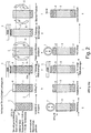
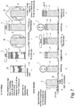
- FIG. 1 In the method steps aj the stepwise construction and the production of a road surface for the production of a road with the system technology according to the invention is shown.
- the substructure should be designed as a fine and mixed-grained soil in the subsurface.
- the proportion of fine soil particles with D ⁇ 0.06 mm is more than 15% of the dry matter.
- Such a substructure 1 would be at risk from frost and water, and therefore it is not possible on such a substructure a cover layer 10, for. As asphalt, apply.
- the substructure 1 is first torn open and loosened up to a layer depth 2 of preferably 10 cm below ground in the direction of the arrows 6, connected with an increase in volume due to the loosening.
- step c the soil stabilizing agent 3 according to the invention (abbreviation: BSM) is applied to this layer over a large area in the direction of arrow 4 and absorbed by the loosened layer.
- BSM soil stabilizing agent 3 according to the invention
- the substructure so impregnated with the soil stabilizing agent 3 in the surface area is milled and mixed in the directions of the arrows 6 to a layer depth of preferably 30 cm, so that the soil stabilizing agent is evenly distributed to the depth of 30 cm in the substrate.
- the soil stabilizing agent 3 in the direction of arrow 4 evenly on the Distributed surface, and included in the near-surface area of the soil.
- step f the entire stabilizing layer 5 impregnated with the soil stabilizing agent is again mixed and dried, whereby the introduced total amount of the soil stabilizing agent 3 is uniformly distributed to a depth of 30 cm in the substrate.
- the converted stabilizing layer 5 is now strongly compressed with a compressor 7, which results in a volume compression and results in a novel load-bearing substrate in the form of the stabilizing layer 5 now present.
- a compensating layer 8 is applied to the converted stabilizing layer 5 and sprayed in step i with the soil stabilizing agent 3 according to the invention in the direction of arrow 4 over a large area and impregnated.
- the compensation layer 8 is partially pressed into the underlying and compressed stabilization layer 5 in step j. This results in a high-strength, frost-resistant and stable base for the subsequent construction of a road surface, consisting of upper bound support layer 34 and a cover layer 10 (see the later figures).
- the FIG. 2 starts from a different starting situation, where it is assumed that, starting from a substructure 1 with less than 15% by mass of fines with D ⁇ 0.06 mm, then in process step b an order of brought mineral soil with a high proportion of fines (eg clay, loam ) hereinafter referred to as clay layer 9, takes place on the substructure.
- a high proportion of fines eg clay, loam
- this layer of clay 9 with the inventive Soil stabilizer 3 sprayed in the direction of arrow 4 over a large area, so that the soil stabilizing agent 3 penetrates into the loose layer.
- step d the milling and mixing is carried out to a depth of 30 cm in the direction of arrows 6, whereby a coherent uniform and homogeneous stabilizing layer 5 is produced.
- the stabilization layer 5 is treated again in step e with the soil stabilizer 3 and in step f in the arrow directions 6 again mixed and dried.
- step g the compression and compression of the impregnated with the soil stabilizing agent stabilizing layer 3 via the compressor 7, and in step h, a leveling layer 8 is applied, which is in turn sprayed in step i with the soil stabilizer 3 in the direction of arrow 4 over a large area.
- the compensating layer 8 is then compacted with the compressor 7, thereby producing a composite with the compacted stabilizing layer 5.
- an upper bound support layer 34 and a cover layer 10, which corresponds to a conventional road surface, are applied to the stabilization layer 5 thus produced with a leveling layer 8 thereon.
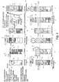
- the embodiment differs according to FIG. 3 from the previous embodiments according to FIG. 1 and 2 only by being in the FIG. 3
- a road with the top edge 32 and a cover layer 10 said cover layer 10 may be made of asphalt or concrete.
- This cover layer 10 is damaged, and it must be made from this damaged road a new road with the substructure according to the invention.
- the existing damaged covering layer 10 and the supporting layer 11 are first of all torn open in the direction of the arrow 6 and mixed with the substrate 1 in method step b.
- the layer depth 2 is given here, for example, at 30 cm below the upper edge 32 of the old cover layer.
- the soil stabilizing agent 3 is then applied over a large area in the direction of arrow 4 to the thus mixed and homogenized layer, which is absorbed in the surface area of the loosened soil.
- the stabilization layer 5 is milled and mixed in the directions of the arrows 6, whereby the soil stabilizer is uniformly distributed in the layer.
- step e the soil stabilizing agent 3 is once again applied over a large area to the stabilization layer 5 prepared in this way in the direction of arrow 4, and in method step f a mixing and simultaneous drying of the stabilizing layer 5 thus homogenized and saturated with the soil stabilizing agent takes place.
- method step g a compression is now carried out with the compressor 7, and in method step h an order is made for a leveling layer 8.
- step i a renewed order of a Soil stabilizer 3 in the direction of arrow 4 on the leveling layer 8, for sealing the surface.
- method step j a compression of the leveling layer 8 and partial impressions in the stabilization layer 5 is effected with the compressor 7 and the now ready prepared substructure is covered in method step k with a conventional upper bound support layer and a cover layer of asphalt or concrete or the like. This creates a new road with a high-strength, frost-proof and stable base.
- the high water permeability of the substrate present in this example makes it possible to distribute the soil stabilizing agent 3 evenly without mechanical mixing in the lower region of the stabilizing layer 5.
- step b first a loosening of the surface with a ripper 14, which in the direction of arrow 15 along the surface of the substructure up to a layer depth 13 of z. B. 5 cm below the top edge 31 moves.
- step c the soil stabilizing agent 3 according to the invention is sprayed onto the loosened surface in the direction of arrow 4. It penetrates by the action of gravity in the direction of arrow 17 in the substructure 1 with the stones and soaked him in step d uniformly, without destroying the dense structure in the underground.
- a suitable soil is obtained from a side extraction and passed through a sieve 19 with a mesh width of 50 mm in the direction of arrow 18, wherein the stones 12 are retained with D> 50 mm and subsequently must not be crushed.
- the sieve leaves only the soil portions with a diameter of ⁇ 50 mm.
- the screen passage 20 with D ⁇ 50 mm is poured in step f in the direction of arrow 21 on the previously loosened and treated with the soil stabilizer existing Planum and distributed in a uniform layer thickness.
- the heaped up layer is impregnated with the soil stabilizing agent 3 according to the invention in the direction of arrow 4, wherein the soil stabilizing agent is taken up by the soil pores in the upper region of the filling.
- this layered layer 22 saturated with the soil stabilizer is mixed and dried and compacted with the compressor 7 in method step i.
- a compensation layer 8 is then applied, which is further impregnated in method step k with the soil stabilizing agent 3 according to the invention in the direction of arrow 4 and impregnated.
- the layers 8 + 22 + 5 thus prepared and impregnated with the soil stabilizing agent 3 are compacted with a compactor 7, whereby a frost-proof and heavy-duty substructure for applying an upper supporting layer 34, e.g. Asphalttrag für, and a cover layer 10, z. As asphalt or concrete, is given.
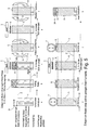
- a build-up layer 23 is applied with a low fines content.
- This build-up layer preferably has particles with a diameter D ⁇ 0.06 mm and ⁇ 15% by mass fraction, for the reduction of the soil present in the subsurface with a very high fines content.
- the structural layer impregnated with the soil stabilizing agent is mixed into the substrate to the depth 2 and the entire stabilizing layer is mixed 5 is mixed and crushed.
- step e a repeated application of the soil stabilizing agent 3 in the direction of arrow 4 takes place on the loosened surface.
- the stabilizing layer 5 is again mixed and dried, so that the total amount of soil stabilizing agent is uniformly distributed in the stabilizing layer, and compressed in step g with the compressor 7.
- a compensating layer 8 is applied and, in method step i, again soaked with the soil stabilizing agent 3 in the direction of arrow 4 and impregnated.
- step j the structure thus produced is again compacted with the compressor 7, so that the leveling layer is partially pressed into the previously compacted stabilization layer, and finally, in method step k, the leveling layer 8, which now firmly and homogeneously the stabilizing layer 5 is connected, a conventional upper bound support layer 34, for example as an asphalt base course, and a cover layer 10, for. As asphalt or concrete, applied.
- the embodiment according to FIG. 6 differs from the aforementioned embodiments according to the FIGS. 1 to 5 merely by additionally adding recycled material to the surface of the existing substrate 1.
- a recycled material may, for. B. unloaded rubble, filter ash, broken brick, concrete break or field stones.
- a frost-prone substructure 1 is assumed, as it is also indicated as a starting point in the aforementioned exemplary embodiments.
- step b an order of the recycled material 24, which may also include stones 12, broken brick, concrete break and field stones if necessary.
- step c a first application of the soil stabilizing agent 3 in the direction of arrow 4 is caused on the layer of recycled material 24, wherein the soil stabilizing agent penetrates in the arrow directions 7 in the applied loose layer and thus produces a homogeneous stabilizing layer 5 in step d if this stabilizing layer milled and mixed.
- a soil stabilizing agent 3 in the direction of arrow 4 is applied to the stabilizing layer 5 homogenized in this way, and in process step f, in turn, this layer impregnated with the soil stabilizing agent is mixed and dried.
- step g the compression is carried out with the compressor 7, and then in step h, a compensation layer 8 is applied.
- step i for the third time the soil stabilizing agent 3 is applied to the leveling layer 8, soaking the leveling layer 8 and sealing the surface.
- the stabilization layer 5 and the leveling layer 8 are densified, so that in method step k a standard upper bound support layer 34, e.g. As asphalt base course, and a cover layer 10, z. B. can be applied from asphalt or concrete.
- a standard upper bound support layer 34 e.g. As asphalt base course, and a cover layer 10, z. B. can be applied from asphalt or concrete.
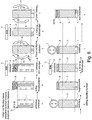
- the embodiment according to FIG. 7 assumes that the entire floor is being made for a new substructure in a bulk storage facility. It is therefore a fine and mixed-grained frost-prone soil, which is delivered to a bulk storage or in a warehouse.
- the proportion of the fine soil particles D ⁇ 0.06 mm is preferably in a proportion of> 15% of the dry matter.
- Such a floor as a proposed substructure for a road would be severely endangered by frost and water and therefore unsuitable.
- step b a first application of the soil stabilizing agent 3 is caused on the delivery floor spread for processing and in process step c, the soil is milled and mixed.
- a second order of the soil stabilizing agent 3 followed by repeated mixing in step e, and the thus homogenized soil for a later stabilization layer 5 is carried out in a protected atmosphere, the z. B. with a cover 27, as protection against precipitation and moisture is stored until further processing.
- a prepared for installation as a stabilization layer 5 soil with optimum water content for the compaction is kept in a warehouse, for example, which can then be used as needed to build a road. This takes place in method step f, where on a Underground 28 a layered installation of the stabilizing layer 5 takes place after the process step e.
- the dumping height of the installation corresponds to the depth of action of the compressor 7 used in method step g. It is assumed that the compressor 7 has such a depth of action that the compaction of the stabilization layer 5 also takes place in the substrate 28 in method step g.
- a compensation layer 8 is applied to the thus homogenized stabilization layer 5 which has been compacted, and in method step i the third application of the soil stabilization agent 3 to the compensation layer 8 takes place.
- method step j the material is compacted and in method step k, a conventional upper bound support layer 34 and a cover layer 10 made of asphalt or concrete can be applied to the thus compacted structure 5, 8.
- FIG. 8 Below a covering layer 10 and upper bound support layer 34 is a leveling layer 8 is arranged, and the upcoming soil of the substrate, which has been repeatedly impregnated and mixed with the soil stabilizing agent 3 and has been converted to a stabilizing layer 5, stored on a substrate 1, which is present at the construction site.
- This substrate 1 may consist of naturally stored loose rock and is usually sensitive to frost. Due to the measures according to the invention, this existing substrate 1 is converted from the existing surface to the working depth of the milling machine into an impregnated stabilizing layer 5 and is therefore highly load-bearing and protected against the influence of frost and water.
- process step (1) a top soil removal takes place
- process step (2) a loosening of Substrate and crushing and mixing with a tiller takes place.
- step (3) the rough planum is prepared, and in step (4), a mixture of water and the soil stabilizer 3 (BSM) according to the invention is introduced according to the manufacturer's instructions and mixed intensively with the soil.
- This soil tilling are preferably used.
- the introduction of the soil stabilizing agent can happen several times after the process steps (4a) and (4b), wherein preferably at least two operations take place.
- process step (5) a fine planum is produced on the surface of this layer.
- this provided as a stabilizing layer 5 soil layer has the optimum water content, to subsequently ensure optimum compaction. If the current water content is higher than the required optimum water content for the compaction, the soil must be dried. If the actual water content is lower than the required optimum water content for the compaction, the soil should be moistened.
- step (7) compression takes place, preferably with a roller (compressor 7), this compressor preferably being intended to have more than 15 t dead weight. This ensures intensive compaction of the stabilization layer 5.
- a compensation layer 8 is installed.
- the upper bound support layer 34 eg as an asphalt base layer
- the cover layer 10 for example, installed as an asphalt surface layer, and the road is so manufactured with the operations described above.
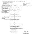
- FIG. 9 In comparison shows the FIG. 9 a conventional construction process and a construction of a conventional road.
- a conventional prior art road consists of a top layer and two underlying base layers, namely an upper bound support layer (OTS) and a lower unbound support layer (UTS), the lower support layer being the preferred is designed as an antifreeze layer.
- OTS upper bound support layer
- UTS lower unbound support layer
- FIG. 9 it is off FIG. 9 recognizable that the existing subsurface is optionally repeatedly subjected to soil consolidation, combined with the incorporation of geotextile and / or geogrid to increase bearing capacity.
- the method steps (1) to (11) show the production of the road structure according to FIG. 9 According to the state of the art.
- the higher effort compared to the method FIG. 8 lies in the fact that an improvement of the underground must take place with conventional stabilization procedures (eg lime stabilization or cement stabilization, that additional components (geotextile, geogrid) are required, but above all: that dredged poorly viable soil of the underground dredged and transported away and thus must be replaced by costly expensive frost-resistant rock mixtures, which must be installed, leveled and compacted as a lower base course.
- conventional stabilization procedures eg lime stabilization or cement stabilization, that additional components (geotextile, geogrid
- step (10) the installation of an upper bonded support layer 34, for example, as an asphalt base course
- step (11) the installation of a cover layer 10, for example as an asphalt surface layer done.
- the comparison of the procedure according to FIG. 9 with the procedure after FIG. 8 shows the advantages of the present invention.
- the present invention dispenses with the multilayer structure of a substructure by delivered frost-resistant rock mixtures as a substitute for removing soil of the substrate, because with the multiple introduction of soil stabilizer in the existing substrate and by repeated mixing and subsequent compaction, a homogeneous stabilizing layer is produced and therefore to a multilayer structure according to FIG. 9 (Prior art) can be dispensed with.
Description
Gegenstand der Erfindung ist eine Systemtechnologie, bestehend aus den Verfahrensanweisungen und einem zur Verfestigung verwendeten Wirkstoff, nachfolgend "Bodenstabilisierungsmittel" genannt, zur Verwendung von nicht für Bauzwecke geeigneten frostgefährdeten, fein- und gemischtkörnigen Mineralböden und deren Umwandlung zu dauerhaft beständigen + frostsicheren + hochtragfähigen Gründungs-, Trag-, Bettungs- und Verfüllschichten im Bauwesen.The invention relates to a system technology consisting of the process instructions and an active ingredient used for solidification, hereinafter referred to as "soil stabilizer", for use of non-construction suitable frost-prone, fine and mixed-grained mineral soils and their conversion to durable + resistant + frost-resistant + high-carrying foundation , Load-bearing, bedding and filling layers in construction.
Die
Die
Die
In der
Die genannten Bodenstabilisierungsmittel zur Bodenstabilisierung haben jedoch den Nachteil, dass eine dauerhafte unzerstörbare Verbesserung der Bodeneigenschaften von frostgefährdeten feinkörnigen und gemischtkörnigen kohäsiven Böden bisher nicht nachgewiesen werden konnte.However, the soil stabilizers mentioned for soil stabilization have the disadvantage that a permanent indestructible improvement in the soil properties of frost-prone fine-grained and mixed-grained cohesive soils could not be detected so far.
Die
Der Erfindung liegt die Aufgabe zugrunde, eine Systemtechnologie zur Bodenstabilisierung, bestehend aus einer Verfahrensvorschrift und einem Bodenstabilisierungsmittel, hinsichtlich des Verfahrensablaufs und der Kosten zu verbessern, um eine dauerhafte unzerstörbare Verbesserung der Bodeneigenschaften von feinkörnigen und gemischtkörnigen, kohäsiven Böden zu erreichen.The invention has for its object to improve a system technology for soil stabilization, consisting of a procedure and a soil stabilizer, in terms of process flow and cost to achieve a permanent indestructible improvement in the soil properties of fine-grained and mixed-grained, cohesive soils.
Zur Lösung der gestellten Aufgabe wird ein Bodenstabilisierungsmittel nach der technischen Lehre des unabhängigen Anspruches 7 vorgeschlagen. Das Verfahren zur Anwendung des Bodenstabilisierungsmittels ist Gegenstand des unabhängigen Anspruches 1.To solve the problem, a soil stabilizer according to the technical teaching of
Ein bevorzugter Anwendungsbereich der Erfindung ist die Durchführung des Verfahrens und die Anwendung des Bodenstabilisierungsmittels als hochtragfähige und frostsichere Gründungs-, Trag-, Bettungs- und Verfüllschichten im Hochbau, im Straßen- und Wegebau und im Erd- und Tiefbau.A preferred field of application of the invention is the implementation of the method and the application of the soil stabilizer as highly load-bearing and frost-resistant foundation, support, bedding and filling layers in building construction, in road and road construction and in earthworks and civil engineering.
Die Anwendung gilt generell für Neubauten und auch für Sanierungen.The application is generally valid for new buildings and also for renovations.
Ein besonders günstiger Anwendungsfall der Erfindung bezieht sich nicht nur auf den Straßenwegebau, sondern auch auf den Hochbau. Im Hochbau werden Gründungschichten verwendet, die als Gründungspolster für Bodenplatten von Gebäuden verwendet werden. Wenn in der Gründungsebene eines Gebäudes keine tragfähige Schicht vorhanden ist, wird das erfindungsgemäße Stabilisierungsmittel auch für die Verfestigung des Untergrundes verwendet.A particularly favorable application of the invention relates not only to road construction, but also to building construction. In building construction, foundations are used, which are used as foundation pads for floor slabs of buildings. If no viable layer is present in the foundation level of a building, the stabilizer according to the invention is also used for the consolidation of the substrate.
Durch die besondere Präparierung der erfindungsgemäßen Gründungs-, Trag-, Bettungs- und Verfüllschichten mit dem erfindungsgemäßen Bodenstabilisierungsmittel besteht der weitere Vorteil, dass aufsteigende Feuchtigkeit aus dem Untergrund und seitlich eindringende Feuchtigkeit abgehalten werden. Sickerwasserschichten werden zuverlässig abgehalten.Due to the special preparation of the foundation, support, bedding and filling layers according to the invention with the soil stabilizer according to the invention, there is the further advantage that rising moisture from the substrate and laterally penetrating moisture are prevented. Leachate layers are reliably prevented.
Somit können auch stabile Verfüllschichten im Hochbau hergestellt werden, die z.B. zur Auffüllung von ausgekofferten Baugruben dienen.Thus, stable backfill layers can also be produced in building construction, e.g. serve to fill up excavated excavations.
Solche stabilisierten Verfüllschichten werden auch im Rohrleitungsbau zur Abdeckung der im Erdboden eingebauten Rohrleitungen verwendet.Such stabilized filler layers are also used in pipeline construction for covering the pipelines installed in the ground.
Damit besteht der Vorteil, dass der vorhandene, aus der Baugrube oder aus dem Rohrgraben entfernte Boden nicht ersatzlos entfernt werden muss, sondern er kann unter Nachbehandlung mit dem erfindungsgemäßen Bodenstabilisierungsmittel wieder eingebaut werden.This has the advantage that the existing, removed from the pit or out of the trench floor must not be removed without replacement, but it can be reinstalled under post-treatment with the soil stabilizer of the invention.
Es können auch bestehende Bauwerke trockengelegt werden, indem der im Baugrubenbereich früher eingebaute Boden abschnittsweise ausgekoffert und nach erfolgter Behandlung mit dem erfindungsgemäßen Bodenstabilisierungsmittel wieder eingebaut wird.Existing structures can also be drained by partially excavating the soil previously installed in the excavation area and re-installing it after treatment with the soil stabilizer according to the invention.
Ein weiterer wichtiger Anwendungsfall der vorliegenden Erfindung liegt in der Behandlung von Wassergräben, bei denen die Sohle oder die Böschungen erosionsgefährdet sind. Auch in diesem Fall können die Sohle oder die Böschungen von Wassergräben durch Behandlung mit dem erfindungsgemäßen Bodenstabilisierungsmittel gegen Erosion gesichert und abgedichtet werden.Another important application of the present invention is in the treatment of moats in which the sole or slopes are susceptible to erosion. Also in this case, the sole or embankments of moats can be secured and sealed against erosion by treatment with the soil stabilizer of the present invention.
Das erfindungsgemäße Bodenstabilisierungsmittel ist sogar zur Herstellung von Blocksteinen oder anderen festen Baukörpern in Modularbauweise geeignet. So ist nach einer Weiterbildung der Erfindung vorgesehen, dass ein mit dem Stabilisierungsmittel behandelter Boden in Formen gepresst und nachfolgend die so hergestellten Bausteine, Baukörper oder andere modulare Bauelemente für den Weiterbau im Hoch oder Tiefbau eingesetzt werden. Diese Elemente sind dann besonders wasserdicht, hoch belastbar und gegen Eindringen von Feuchtigkeit geschützt.The soil stabilizer of the invention is even suitable for the production of blocks or other solid structures in a modular design. Thus, according to a development of the invention, it is provided that a soil treated with the stabilizing agent is pressed into molds and subsequently the building blocks, structural elements or other modular building elements thus produced are used for further construction in civil engineering. These elements are then particularly waterproof, highly resilient and protected against ingress of moisture.
Der Einsatz des erfindungsgemäßen Bodenstabilisierungmittels ist auch für den Deichbau oder die Deichsanierung geeignet. Es kann sowohl der gesamte Baukörper eines Deiches oder auch nur wasser-beanspruchte Teile eines Deiches (z.B. auch die Dichtungsschürze) gegen Eindringen von Druckwasser geschützt werden.The use of the soil stabilizer according to the invention is also suitable for dyke construction or dyke restoration. It can both the entire structure of a dike or even water-stressed parts of a dike (such as the sealing apron) are protected against ingress of pressurized water.
Wesentliches Merkmal des Bodenstabilisierungsmittels ist, dass eine dauerhafte Reduzierung der Wasserbindungskräfte der feinen Bodenbestandteile dieser Böden durch ein Bodenstabilisierungsmittel gelingt, das als Ionenaustauscher und Katalysator wirkt.An essential feature of the soil stabilizer is that a permanent reduction of the water binding forces of the fine soil components of these soils is achieved by a soil stabilizer acting as an ion exchanger and catalyst.
Bei dem verwendeten Bodenstabilisierungsmittel handelt sich um eine leicht wasserlösliche, klare Flüssigkeit, deren chemische Zusammensetzung eine Mischung aus verschiedenen Sulfonsäuren + speziellen Zusätzen + Wasser ist. Die Viskosität ist ölartig.The soil stabilizer used is a slightly water-soluble, clear liquid whose chemical composition is a mixture of different sulfonic acids + special additives + water. The viscosity is oily.
Ein Hauptbestandteil der Wirkstoffe des Bodenstabilisierungsmittels ist eine Mischung verschiedener Sulfonsäuren, die als gemeinsames Merkmal die funktionelle Gruppe -S03H haben, verknüpft mit einem wasserabweisenden organischen Bestandteil R. Die Darstellung ist: R - S03 - H.A major constituent of the active ingredients of the soil stabilizer is a mixture of various sulfonic acids which share the common functional group -SO 3 H linked to a water repellent organic component R. The representation is: R - SO 3 - H.
Die Sulfonsäuren dissoziieren in Wasser. Das erfindungsgemäße Bodenstabilisierungsmittel wirkt im Boden als Ionenaustauscher und Katalysator.The sulfonic acids dissociate in water. The soil stabilizer of the invention acts as an ion exchanger and catalyst in the soil.
Das Bodenstabilisierungsmittel bewirkt, dass die an der Oberfläche der Bodenpartikel adhäsiv gebundenen Wasserstoff-Ionen H+, (und damit das über Wasserstoffbrücken an diese Ionen angelagerte Wasser) verdrängt und ersetzt werden durch in der Wasserhülle vorhandenen (+)-Metall-Ionen, z.B. Na+; K+: Mg++; Ca++; AI+++;The soil stabilizer causes the hydrogen ions H +, (and thus the water attached to these ions via hydrogen bonding), which are adhesively bound to the surface of the soil particles, to be displaced and replaced by (+) metal ions present in the water shell, e.g. Na +; K +: Mg ++; Ca ++; AI +++;
Damit wird ein großer Teil des fest gebundenen Adhäsionswassers von der Oberfläche der Bodenpartikel entfernt, indem es zu freiem Porenwasser umgewandelt wird. Dieses freie Wasser kann durch Austrocknung leicht aus dem Boden entweichen oder in den Porenraum zwischen den Bodenpartikeln abwandern.Thus, a large part of the firmly adhered adhesive water is removed from the surface of the soil particles by being converted to free pore water. This free water can be easily removed by dehydration escape the soil or migrate into the pore space between the soil particles.
Das erfindungsgemäße Bodenstabilisierungsmittel bewirkt weiterhin, dass die an die Bodenpartikel gebundenen (+)-Metall-Ionen kein Hydratwasser mehr anlagern können, indem sich in die im Bodenstabilisierungsmittel enthaltene Säure-Rest-Ionen mit den (+)-Metall-Ionen verbinden. Es handelt sich also um eine Reduzierung der Adsorbtionswasserhülle durch einen Ionen-Austauschmechanismus.The soil stabilizer according to the invention furthermore has the effect that the (+) metal ions bound to the soil particles can no longer accumulate water of hydration by combining with the (+) metal ions in the acid-residual ions contained in the soil stabilizer. It is therefore a reduction of Adsorbtionswasserhülle by an ion exchange mechanism.
Ein weiterer Effekt erfolgt durch eine Hydrophobierung ("Wasserabweisende Imprägnierung")-der Bodenpartikel.Another effect is provided by a hydrophobing ("water-repellent impregnation") - the soil particles.
Die im Bodenstabilisierungsmittel enthaltenen und sich an die Metall-Ionen anlagernden Säure-Rest-Ionen sind mit einem hydrophoben organischen Anteil verknüpft. Die hydrophoben Bestandteile bewirken, dass im verdichteten Boden kein Wasser mehr im Porenraum transportiert werden kann.The acid-residual ions contained in the soil stabilizer and attached to the metal ions are linked to a hydrophobic organic moiety. The hydrophobic components cause that in the compacted soil no more water can be transported in the pore space.
Die bei der Dissoziation im erfindungsgemäßen Bodenstabilisierungsmittel frei werdenden Wasserstoff-Ionen H+ reagieren unmittelbar mit den in der Wasserhülle vorhandene Hydroxyl-Ionen OH- zu Hydronium-Ionen H3O+ und in einem weiteren Schritt zu Wasser H2O. Damit ist die Säurewirkung eliminiert und eine Neutralisation hat stattgefunden.The hydrogen ions H + released during dissociation in the soil stabilizer according to the invention react directly with the hydroxyl ions OH - present in the water shell to form hydronium ions H3O + and in a further step to water H2O. Thus, the acid effect is eliminated and neutralization has occurred.
Die chemischen Reaktionen, die durch das erfindungsgemäße Bodenstabilisierungsmittel im Boden bewirkt werden, sind irreversibel. Die Veränderung der Bodeneigenschaften ist somit dauerhaft. Die durch die Wirkung des vom Bodenstabilisierungsmittel reduzierten Adsorbtionswasserhüllen können nicht mehr aufgebaut werden.The chemical reactions caused by the soil stabilizer of the invention in the soil are irreversible. The change in soil properties is thus permanent. The reduced by the action of the soil stabilizer Adsorbtionswasserhüllen can not be built.
Wegen der dauerhaft reduzierten Wasserhüllen um die Bodenpartikel können die mit dem Bodenstabilisierungsmittel behandelten Böden im Zustand des für die Verdichtung erforderlichen optimalen Wassergehaltes im Boden bei gleicher Verdichtungsarbeit zu höherer Trockendichte verdichtet werden als nicht mit dem Bodenstabilisierungsmittel behandelter Boden.Because of the permanently reduced water envelopes around the soil particles, the soils treated with the soil stabilizer may contribute to the optimum soil water content required for compaction the same compaction work to higher density of dry compacted than not treated with the soil stabilizer soil.
Durch die dichtere Lage der Bodenpartikel zueinander werden bestehende molekulare Nahwirkungskräfte zwischen den Bodenpartikeln verstärkt, die zu einer Erhöhung der Festigkeit und damit der Tragfähigkeit führen. Diese Wirkung geht nicht mehr verloren und bleibt somit dauerhaft.Due to the denser position of the soil particles to each other existing molecular forces of proximity between the soil particles are reinforced, which lead to an increase in strength and thus the carrying capacity. This effect is no longer lost and thus remains permanent.
Die hydrophoben (wasserabweisenden) Bestandteile vom Bodenstabilisierungsmittel bewirken, dass in einem mit dem Bodenstabilisierungsmittel nach den Verwendungsvorschriften behandelten und verdichteten Boden der kapillare Wasseraufstieg unterbunden ist und das Eindringen von Wasser in den verdichteten Bodenkörper überhaupt verhindert wird.The hydrophobic (water-repellent) constituents of the soil stabilizer cause capillary water rise to be prevented in a soil treated and compacted with the soil stabilizer in accordance with the instructions for use and the penetration of water into the compacted soil body is prevented at all.
Beim Gefrieren des Bodens fehlt dadurch der Wassernachschub von unten in die Gefrierzone, der Frost kann keine Gefügeänderungen bewirken, der Boden ist frostsicher.When freezing the soil thereby lacks the supply of water from below into the freezing zone, the frost can cause no structural changes, the ground is frost-proof.
Die Mehrzahl der vorkommenden Lockergesteine an der Erdoberfläche in vielen Ländern der Welt sind fein- und gemischtkörnige .Mineralböden, die wegen ihres Gehaltes an Feinstoffen und der damit verbundenen Wasser- und Frostempfindlichkeit nicht für Bauzwecke geeignet sind und deshalb für Bauzwecke, insbesondere aber im konventionellen Straßen- und Wegebau gegen frostsichere und wasserunempfindliche Mineralgemische ausgetauscht werden müssen.The majority of the loose rocks on the surface of the earth in many countries of the world are fine and mixed-grained mineral soils, which are not suitable for building because of their content of fines and the associated sensitivity to water and frost and therefore for construction purposes, but especially in conventional roads - and road construction against frost-proof and water-resistant mineral mixtures must be replaced.
Dies betrifft die Bodenarten: Ton, Schluff (auch bezeichnet als Silt oder Staubsand), mineralische Gemische aus Steinen, Kies oder Sand jeweils mit Beimengungen von mehr als 15 Masse-% an Schluff und/oder Ton: wie z.B. toniger Sand, schluffiger Sand, tonig- schluffiger Sand, toniger Kiessand, schluffiger Kiessand, tonig-schluffiger Kiessand, Lehm (Gemisch aus Feinsand + Schluff + Ton), natürliche oder gebrochene Gesteinsgemische.This applies to the soil types: clay, silt (also called silt or dust sand), mineral mixtures of stones, gravel or sand, each with admixtures of more than 15% by mass of silt and / or clay: such as clayey sand, silty sand, clayey silty sand, clayey gravel sand, silty gravel sand, clayey silty gravel sand, loam (mixture of fine sand + silt + clay), natural or broken rock mixtures.
Das erfindungsgemäße Bodenstabilisierungsmittel kann allgemein im Bauwesen verwendet werden, insbesondere im Straßen- und Wegebau, im Erdbau und im Grundbau zwecks Verfestigung der frostgefährdeten, feinkörnigen und gemischtkörnigen Lockergesteine. Diese Mineralböden müssen nicht mehr wie bisher von der Baustelle entfernt werden und durch frostsichere Mineralgemische (als Frostschutzschicht, Schottertragschicht, Kiestragschicht) ersetzt werden. Vielmehr wird der auf der Baustelle anstehende Boden vor Ort mit dem Bodenstabilisierungsmittel behandelt und nach anschließender Verdichtung zu dauerhaft beständigen + frostsicheren + hochtragfähigen Konstruktionsschichten umgewandelt.The soil stabilizer according to the invention can generally be used in construction, in particular in road construction and road construction, earthworks and foundations for the purpose of solidifying the frost-prone, fine-grained and mixed-grained loosened rocks. These mineral soils no longer have to be removed from the construction site as before and replaced by frost-proof mineral mixtures (as antifreeze layer, gravel base layer, gravel layer). Rather, the soil present on the construction site is treated on site with the soil stabilizer and, after subsequent compaction, converted into permanently resistant + frost-resistant + highly loadable construction layers.
Bodenmechanische Einordnung der für die mit dem Bodenstabilisierungsmittel zu behandelnden, geeigneten Böden:
Für den optimalen Erfolg bei der Anwendung des Bodenstabilisierungsmittels müssen die zu verwendenden Mineralböden folgende bodenmechanischen Eigenschaften A + B + C + D besitzen, die in bodenmechanischen Laboruntersuchungen ermittelt werden. Die überwiegend anzutreffenden Böden sind für die Verfestigung mit dem Bodenstabilisierungsmittel geeignet.Soil mechanical classification of the suitable soils to be treated with the soil stabilizer:
For optimum success in the application of the soil stabilizer, the mineral soils to be used must have the following soil mechanical properties A + B + C + D, which are determined in soil mechanical laboratory tests. The predominant soils are suitable for solidification with the soil stabilizer.
Böden mit abweichenden Kennwerten können gezielt vorbehandelt und dann ebenso mit dem Bodenstabilisierungsmittel verfestigt werden
- A) Anteil der feinen Bodenpartikel mit D äqu < 0,06 mm : > 15 Masse% bezogen auf die Trockenmasse; Messung des Anteils durch Absiebung oder durch die Bestimmung der Korngrößenverteilung im feinen Bereich, z.B. durch Sedimentationsanalyse im Labor, oder durch andere gebräuchliche Verfahren zur Ermittlung der Korngrößenverteilung;
In Mineralböden, bei denen der Anteil der feinen Partikel wenigerals 15 Masse% beträgt, können andere Mineralböden mit deutlich mehr Anteilen an Feinstoffen, z.B. Ton oder Lehm, eingemischt werden, die auf anderen Baustellen entsorgt werden müssen, so dass der Anteil Feinstoffe an der Gesamtmasse der vermischten Böden alsErgebnis mehr als 15 Masse% beträgt. Geeignet als Additive sind auch Recycling-Materialien mit hohem Feinstoff-Anteil, z.B. Kraftwerksasche. Der Vorteil liegt darin, dass diese für andere Bauzwecke nicht verwendbaren Materialien sehr kostengünstig beschafft werden können und somit von anderen Nutzern nicht als Abfall entsorgt werden müssen. - B) Plastizität > 10
Plastizität in der Bodenmechanik ist die Differenz zwischen dem Wassergehalt an der Fließgrenze (= liquid limit) und dem Wassergehalt an der Ausrollgrenze (= plastic limit).
Wenn die Plastizität < 10 ist, können geeignete Additive nach Teil A eingemischt werden, bis die Eignung erreicht ist. - C) Der Anteil an organischen Beimengungen (z.B. Humus)
muss kleiner als 4 Masse-% sein, bezogen auf die Trockenmasse. - D) Der pH-Wert des Bodens muss
größer als pH 6 sein,
wenn er kleinerist als pH 6, kann der Boden durch spezielle Vorbehandlung geeignet gemacht werden.
- 1. Funktion der Bodenpartikel
Alle Bodenpartikel sind von einer Wasserhülle umgeben.
Grobe Bodenpartikel haben eine geringe spezifische Oberfläche und können je Masseeinheit nur eine geringe Wassermenge an der Oberfläche binden. Es überwiegen Druck, Reibung und Verzahnung bei der Kraftübertragung zwischen den Körnern.
Feine Bodenpartikel haben eine große spezifische Oberfläche und können je Masseeinheit eine große Menge Wasser an die Partikeloberfläche binden. Es überwiegt die wassergehaltsabhängige Kohäsion. Bei Wasserzutritt vergrößern sich die Wasserhüllen um die Bodenpartikel und drücken die Partikel gegenseitig voneinander weg, dadurch verringern sich die Bindungskräfte, die Festigkeit und Tragfähigkeit von feinkörnigen Böden geht mit zunehmendem Wassergehalt verloren.
Bei gemischtkörnigen Böden mit einem Feinstoffanteil von > 15 Masse-% werden die Bodeneigenschaften überwiegend durch die oberflächenaktiven Eigenschaften der Feinstoffe bestimmt.
Die Anteile und Verteilung der Einzelmassen der einzelnen Korngröße-Fraktionen an der Gesamtmasse einer Bodenprobe eines Mineral-Bodens bezeichnet man als Korngrößenverteilung.
Sie ist ein wichtiges Arbeitsmittel zur Beurteilung von Mineralböden hinsichtlich ihrer bodenmechanischen Eigenschaften für Bauzwecke.
Die Trennung der Kornfraktionen erfolgt bei rein grobkörnigen Böden durch Siebanalyse und bei feinkörnigen Böden durch die Sedimentationsanalyse.
Die Verteilung der Kornfraktionen wird für gemischtkörnige Böden, die sowohl grobkörnige als auch feinkörnige Anteile enthalten, mit einer Kombination aus Siebanalyse und Sedimentationsanalyse bestimmt.
Die grafische Darstellung der Korngrößenverteilung erfolgt vorzugsweise als Summenlinie. - 2. Über die Wirkungsweise des Wassers in feinkörnigen Böden
Austrocknung bewirkt eine Reduzierung der Wasserhüllen um die Bodenpartikel, die wird als "Schwinden" des Bodens" bezeichnet, was einer Annäherung der Bodenpartikel entspricht.
Dadurch erfolgt eine Vergrößerung der Bindungskräfte zwischen den Partikeln durch verringerten Abstand untereinander und durch Anstieg der Saugspannung des "Meniskus-Wassers" an den Berührungspunkten der Partikel. Damit ist ein Anstieg der Festigkeit und Tragfähigkeit der feinkörnigen Böden verbunden.
Bei Wasserzutritt erfolgt eine Vergrößerung der Wasserhüllen - sogenanntes "Aufquellen" des Bodens und somit ein gegenseitiges "Voneinander-Wegdrücken" der Bodenpartikel über die Wasserhüllen. Daraus folgt eine Verringerung der Bindungskräfte zwischen den Partikeln durch vergrößerten Abstand untereinander und durch Reduzierung der Saugspannung des Wassers an den Berührungspunkten der Partikel. Hieraus folgt ein Verlust der Festigkeit und Tragfähigkeit der fein- und gemischtkörnigen Böden.
Hier setzt die Erfindung ein, die beim Einmischen des erfindungsgemäßen Bodenstabilisierungsmittels in den Boden eine dauerhafte Reduzierung der Wasserhüllen erreicht. Es erfolgt keine Vergrößerung dieser Wasserhüllen mehr bei erneutem Wasserzutritt.
Dadurch ist eine bessere gegenseitige Annäherung der Bodenpartikel durch Verdichtung wegen reduzierter Wasserhüllen gewährleistet.
Ebenso erfolgt eine Vergrößerung der Bindungskräfte zwischen den Partikeln durch verringerten Abstand untereinander und durch Anstieg der Saugspannung des "Meniskus-Wassers" an den Berührungspunkten der Partikel. Daraus resultiert ein Anstieg der Festigkeit und Tragfähigkeit der feinkörnigen Böden.
Daraus ergeben sich eine dichtere Packung der Partikel wegen der reduzierten Wasserhüllen und keine Dichteveränderung und kein Festigkeitsverlust mehr bei Wasserzutritt und bei Frost. - 3. Über die Wirkungsweise des Bodenstabilisierungsmittels in feinkörnigen Böden als Katalysator und Ionenaustauscher
Das Bodenstabilisierungsmittel ist kein Bindemittel wie Kalk oder Zement. Bei der Anwendung des Bodenstabilisierungsmittels im Boden werden keine Kristallstrukturen zwischen den Bodenpartikeln aufgebaut. Der Festigkeitszuwachs bei der Anwendung des Bodenstabilisierungsmittels resultiert aus der engeren Annäherung der Bodenpartikel bei der Bodenverdichtung durch eine erhebliche und unumkehrbare Reduzierung der Größe der die Partikel umgebenden adsorbierten Wasserhüllen.
Es gibt dabei drei verschiedene Funktionsmechanismen:- 3. 1. Reduzierung der Adsorbtionswasserhülle durch Austauschmechanismus 1 Das Bodenstabilisierungsmittel bewirkt, dass ein großer Teil der an der Oberfläche der Bodenpartikel gebundenen Wasserstoff-Ionen H+, (und das damit über Wasserstoffbrücken an diese Ionen weitere angelagerte Wasser) ersetzt werden durch in der Wasserhülle vorhandene (+)-Metall-Ionen, z.B. Na+; K+: Mg++; Ca++; Al+++;
Damit wird ein großer Teil des fest gebundenen Adhäsionswassers von der Oberfläche der Bodenpartikel gelöst, indem es zu freiem Porenwasser umgewandelt wird. Dieses freie Wasser kann durch Austrocknung leicht aus dem Boden entweichen oder sich im Porenraum zwischen den Bodenpartikeln verteilen. - 3. 2. Reduzierung der Adsorbtionswasserhülle durch Austauschmechanismus 2 Das Bodenstabilisierungsmittel bewirkt weiterhin, dass die an die Bodenpartikel gebundenen (+)-Metall-Ionen kein Hydratwasser mehr anlagern können, indem sich stattdessen die in dem Bodenstabilisierungsmittel enthaltenen Säure-Rest-Ionen (Sulfat-Gruppe) mit den (+) Metall-Ionen verbinden.
- 3.3 Hydrophobierung ("Wasserabweisende Imprägnierung")
Die in dem Bodenstabilisierungsmittel enthaltenen und sich an die Metall-Ionen anlagernden Säure-Rest-Ionen (Sulfat-Gruppe) sind mit einem hydrophoben organischen Anteil verknüpft. Dieser bewirkt, dass die feinen Bodenpartikel die Fähigkeit verlieren, Wasser an der Partikel-Oberfläche aufzunehmen und dass der mit dem Stabilisierungsmittel behandelnde Boden die Fähigkeit verliert Wasser in den Kapillaren zu transportieren. - 3.4 Neutralisierung
Die bei der Dissoziation von im Bodenstabilisierungsmittel frei werdenden Wasserstoff-Ionen H+ reagieren unmittelbar mit den in der Wasserhülle vorhandenen Hydroxyl-Ionen OH- zu Hydronium-Ionen H3O+ und in einem weiteren Schritt zu Wasser H2O. Damit ist die Säurewirkung eliminiert.
- 3. 1. Reduzierung der Adsorbtionswasserhülle durch Austauschmechanismus 1 Das Bodenstabilisierungsmittel bewirkt, dass ein großer Teil der an der Oberfläche der Bodenpartikel gebundenen Wasserstoff-Ionen H+, (und das damit über Wasserstoffbrücken an diese Ionen weitere angelagerte Wasser) ersetzt werden durch in der Wasserhülle vorhandene (+)-Metall-Ionen, z.B. Na+; K+: Mg++; Ca++; Al+++;
- 4. Kurzfassung der erfindungsgemäßen Systemtechnologie zur dauerhaften und frostsicheren Verfestigung von fein- und gemischtkörnigen Mineralböden am Beispiel des Straßen- und Wegebaus
- 4.1 Boden hinsichtlich der Eignung zur Anwendung der Systemtechnologie prüfen
- 4.2 Oberfläche des Planums aufreißen und auflockern
- 4.3 Bodenstabilisierungsmittel verdünnt mit Wasser in mehreren Arbeitsgängen in den Boden einbringen und vermischen
- 4.4 Boden im Zustand des für die Verdichtung optimalen Wassergehaltes verdichten
- 5. Detaillierte erfindungsgemäße Systemtechnologie zur dauerhaften und frostsicheren Verfestigung von fein- und gemischtkörnigen Mineralböden am Beispiel des Straßen- und Wegebaus
- 5.1 Erkundung des Untergrundes
für die zu bauenden Straßen und Wege, Durchführung des für diese Systemtechnologie entwickelten Eignungstestes, und von ausgewählten bodenmechanischen Untersuchungen im Labor, besonders zur Ermittlung des Anteils an Feinstoffen im Boden mit einem Partikeldurchmesser < 0,06 mm zur Festlegung der Aufwandsmenge des Bodenstabilisierungsmittels, sowie zur Ermittlung eines für die Verdichtung des Bodens erforderlichen optimalen Wassergehaltes. - 5.2 Gradiente und Profil der Straße (des Weges) abstecken
Benötigte Geräte: Vermessungsgeräte - 5.3 Vegetation, Humus + Bodenschichten mit einem Anteil > 4% von organischen Beimengungen entfernen.
Benötigte Geräte z.B. Planierraupe, oder Bulldozer, oder Grader oder Bankettfräse - 5.4 Bodenanalyse auf der Baustelle,
Entnahme einer Bodenprobe zur Bestimmung des aktuellen Wassergehaltes des Bodens, Entnahmetiefe unter Planum entsprechend der vorgesehenen Arbeitstiefe der Boden-Mischfräse, inder Regel bis 30 cm tief
Benötigte Geräte: geeignete Vorrichtung zur schnellen Ermittlung des Wassergehaltes von Mineralböden.
Ergebnis der Prüfung ist der aktuelle Wassergehalte w im Boden bis zur Arbeitstiefe der Fräse und dient zur Berechnung der Wassermenge, mit der das Bodenstabilisierungsmittel verdünnt und in den Boden eingebracht wird. - 5.5 Grobplanum herstellen, entsprechend den Planvorgaben,
benötigte Geräte: Grader
Quergefälle muss parallel zum Gefälle der späteren Deckschicht verlaufen. Nachträglich, nachdem das Bodenstabilisierungsmittel auf dem aufgelockerten Planum verteilt wurde, dürfen keine größeren Bodenbewegungen und Bodenverschiebungen mehr erfolgen, damit die Tiefe der Bodenbehandlung mit dem Bodenstabilisierungsmittel nicht stellenweise reduziert wird. - 5.6 Aufreißen und Auflockern des Planums
ca. 10 cm tief zur gleichmäßigen Aufnahme des Bodenstabilisierungsmittels Benötigte Geräte: z.B. Aufreißer oder Ripper oder Kultivator oder Federzinken-Egge oder Scheiben- Eggeoder Fräse bis 10 cm tief. - 5.7 Messung des aktuellen Wassergehaltes im Boden, Ermittlung der Wassermenge, mit dem das Bodenstabilisierungsmittel verdünnt wird, um in den Boden eingebracht zu werden, damit nach Einbringen der Arbeitslösung, bestehend aus dem Bodenstabilisierungsmittel + Wasser, der Wassergehalt im Boden nicht
mehr als 2% über dem für die bestmögliche Verdichtung des Bodens erforderlichen optimalen Wassergehalt w optimal liegt, dieser Wassergehalt wurde vor Baubeginn im Labor ermittelt. - 5.8
die 1. Teilmenge einer Arbeitslösung bestehend aus dem Bodenstabilisierungsmittel + Wasser in einem Tank herstellen und mischen für 1. Arbeitsgang, Menge des einzubringenden Bodenstabilisierungsmittels ermitteln in Abhängigkeit von Anteil der Feinbestandteile D < 0,06 mm im Boden.
Alternativ: berechnete Menge des Bodenstabilisierungsmittels + Wasser separat bereitstellen zum Vermischen erst während des Einbringens in den Boden. - 5.9
die 1. Teilmenge der Arbeitslösung aus dem Bodenstabilisierungsmittel + Wasser gleichmäßig auf das vorher aufgelockerte Planum in den Boden einbringen
Einbring-Variante 1: das Bodenstabilisierungsmittel wird vorab in einem fahrbaren Tank mit Wasser gemischt, und im freien Gefälle über ein Verteilerrohr mit Ausbringdüsen auf das Planum aufgebracht, die Auslaufmenge aus dem Verteilerrohr bestimmt die Fahrgeschwindigkeit
Einbring-Variante 2: das Bodenstabilisierungsmittel wird vorab in einem fahrbaren Tank mit Wasser gemischt, und über Pumpen und weiter über ein Verteilerrohr mit Ausbringdüsen auf das Planum aufgebracht, die Pumpenfördermenge und die Fahrgeschwindigkeit werden entsprechend der vorgesehenen Aufwandsmenge geregelt
Einbring-Variante 3: das Bodenstabilisierungsmittel wird vorab in einem fahrbaren Tank mit Wasser gemischt, und über Pumpen und weiter über ein Verteilerrohr mit Ausbringdüsen innerhalb der Bodenmischfräse während des Fräsvorganges in den Boden eingebracht, die Pumpenfördermenge und die Fahrgeschwindigkeit der Fräse werden entsprechend der vorgesehenen Aufwandsmenge geregelt
Einbring-Variante 4: die zur Verdünnung erforderliche Menge Wasser wird in einem fahrbaren Tank bereitgestellt, das Bodenstabilisierungsmittel wird im Anliefergebinde (200-Liter-Fass oder 1000-Liter-Eurocontainer) auf dem Tankfahrzeug platziert oder auf einem mit dem Tankfahrzeug gekoppelten Anhänger. Über separate Pumpen werden beide Komponenten getrennt gefördert in einen Mischbehälter und weiter über ein Verteilerrohr mit Ausbringdüsen in den Boden eingebracht, die Pumpenfördermengen und die Fahrgeschwindigkeit des Tankfahrzeuges werden entsprechend der vorgesehenen Aufwandsmengen geregelt, wobei das Verdünnungsverhältnis zwischen dem Bodenstabilisierungsmittel und Wasser während des Einbringens in den Boden verändert werden kann.
Einbring-Variante 5: das Bodenstabilisierungsmittel und ca. die 10-fache Menge Wasser in einer tragbaren Druckspritze mischen und von Hand in den zu behandelnden Boden einbringen, für Kleinflächen und kleine Bodenmengen und für ausgewählte Bereiche mit extrem hohem natürlichen Wassergehalt; - 5.10 Boden zerkleinern und intensiv mit dem Bodenstabilisierungsmittel vermischen, Arbeitstiefe der Boden-Mischfräse min.
bis 30 cm unter Planum, mit Spurüberlappung.
Benötigte Geräte: Geeignete Boden-Misch-Fräse - 5.11 Oberfläche ausgleichen, Wellen der Arbeitsspuren der Fräse einebnen, verfestigte Stellen im Untergrund auflockern, besonders an den Rändern der Arbeitsspuren der Boden-Misch-Fräse; dabei den Boden weiter mischen, in mehreren Übergängen.
Benötigte Geräte: Ripper oder Kultivator oder Federzinken-Egge oder Scheiben- Egge, oder Boden-Mischfräse - 5.12
die 2. Teilmenge einer Arbeitslösung bestehend aus dem Bodenstabilisierungsmittel + Wasser in einem Tank herstellen und mischen für 2. Arbeitsgang, Bedarf an Bodenstabilisierungsmittel + Wasser ermitteln in Abhängigkeit von Anteil der Feinbestandteile D < 0,06 mm im Boden.
Alternativ: berechnete Menge des Bodenstabilisierungsmittels + Wasser bereitstellen zum Vermischen während des Einbringens in den Boden. - 5.13
die 2. Teilmenge der Arbeitslösung aus dem Bodenstabilisierungsmittel + Wasser gleichmäßig auf das aufgelockerte Planum in den Boden einbringen. Varianten zum Einbringen wie unter Punkt 5.9 - 5.14 Boden weiter intensiv mischen,
Arbeitstiefe bis 30 cm unter Planum, mit Spurüberlappung.
Benötigte Geräte: Geeignete Boden-Misch-Fräse - 5.15 Oberfläche ausgleichen, Wellen der Arbeitsspuren der Fräse einebnen, verfestigte Stellen im Untergrund auflockern, besonders an den Rändern der Arbeitsspuren der Boden-Misch-Fräse; dabei den Boden weiter mischen, in mehreren Übergängen.
Benötigte Geräte: Ripper oder Kultivator oder Federzinken-Egge oder Scheiben- Egge, Boden-Mischfräse - 5.16 Kontrolle des aktuellen Wassergehaltes w im Boden vor der Verdichtung: Ist der aktuelle Wassergehalt w höher als der ermittelte optimale Wassergehalt w opt für die Verdichtung, ist ein Trocknen und weiteres Mischen und des Bodens erforderlich, bis w = w opt.
Ist der Wassergehalt w geringer als der ermittelte optimale Wassergehalt für die Verdichtung, ist ein Anfeuchten und weiteres Mischen des Bodens erforderlich, bis w = w opt. - 5.17 Feinplanum herstellen.
Benötigtes Gerät: Grader und Vorrichtungen zur Gefällemessung - 5.18 Boden von der Oberfläche des Planums her verdichten,
Verdichtungsablauf immer vom Rand zur Mitte der Straße/des Weges, vorzugsweise durch stufenweises Einbringen der Verdichtungsenergie. Dies wird beginnend mit leichten Verdichtungsgeräten, z. B. mit Vibrationsplattenverdichtern, durchgeführt. Weiterführend mit schweren Verdichtungsgeräten z.B. mittels Walzen mit > 15 t Eigenmasse ohne Vibration, dann weiterführende Verdichtung mit Walzen mit > 15 t Eigenmasse mit Vibration und abschließende Verdichtung mit schwerer Gummirad-Walze. - 5.19 Während der Verdichtung mit Walzen mit > 15 t Eigenmasse mit Vibration wird eine ca. 5 cm verdichtete Ausgleichsschicht aus einem groben gebrochenen, frostsicheren Gesteinsgemisch ohne Feinanteile D< 0,06 mm, z.B.
Splitt 16/32 mm, auf das Erdplanum aufgebracht und in gleichmäßiger Schichtdicke verteilt.
Dies hat zu einem Zeitpunkt zu erfolgen, wenn sich die gebrochenen groben Körner noch zum Teil in das Planum der Stabilisierungsschicht eindrücken lassen.
(Die Ausgleichsschicht hat die Aufgabe, bei direkt befahrenen Straßen und Wegen ohne zusätzliche gebundene Deckschicht die Reibung zwischen den Rädern der Fahrzeuge und der festen glatten verdichteten Oberfläche der Stabilisierungsschicht sicherzustellen.
Bei Straßen und Wegen, die in einem weiteren Arbeitsgang mit einer zusätzlichen Deckschicht belegt werden, sichert diese Ausgleichsschicht die Reibung und Verzahnung zwischen Deckschicht und der Oberfläche der verdichteten Stabilisierungsschicht.) - 5.20
die 3. Teilmenge der Arbeitslösung aus dem Bodenstabilisierungsmittel + Wasser gleichmäßig auf die Ausgleichsschicht aufbringen, ohne Einmischen - 5.21 Abschluss der Verdichtung, wenn die Messungen nach 5.21; 5.22 und 5.23 eine ausreichende Verdichtung nachweisen, ansonsten Weiterverdichtung mit schweren Verdichtungsgeräten nach 5.18
- 5.22 Ermittlung der erreichten Trocken-Dichte mit dem Ausstech-Zylinder (bei feinkörnigen Böden ohne Steine) oder z.B. mit dem Bodendensitometer oder anderen geeigneten Messverfahren(bei Böden mit Steinen)
- 5.21 Messung der erreichten Tragfähigkeit auf dem verdichteten Planum, 24 h nach Abschluss der Verdichtung, mit dem Statischen Plattendruckgerät,
Ermittlung der Last-Setzungs-Kurve bei stufenweiser Lasteintragung der statischen Lasten auf eineBelastungsplatte von 30 cm Durchmesser Messergebnis = EV2 [MPa] - 5.22 Messung der erreichten Tragfähigkeit auf dem verdichteten Planum, 24 h nach Abschluss der Verdichtung, mit dem Dynamischen Plattendruckgerät, Ermittlung der Einsenktiefe und Einsenkgeschwindigkeit einer
Belastungsplatte von 30 cm Durchmesser beim Aufschlagen eines Fallgewichtes Messergebnis = EV dyn [MPa]
Mit diesen Arbeitsgängen wird aus dem frostgefährdeten fein- und gemischtkörnigen Boden des Untergrundes eine dauerhaft hochtragfähige frostsichere untere Tragschicht im Straßenbau hergestellt, vorbereitet zum Aufbringen einer gebundenen Deckschicht aus Asphalt oder Beton.
Bei untergeordneten Straßen und Wirtschaftswegen kann diese so erstellte verfestigte Schicht ohne zusätzliche Deckschicht direkt befahren werden.
- 5.1 Erkundung des Untergrundes
- 6. Wirkungen der Anwendung des Bodenstabilisierungsmittels
Die neuen Eigenschaften der mit dem Bodenstabilisierungsmittel behandelten Böden nach der Verdichtung zu Konstruktionsschichten im Straßen- und Wegebau führen zu einer hohen dauerhaften und unzerstörbaren Festigkeit und Tragfähigkeit, sowie zu einer dauerhaften Beständigkeit gegen Wassereinwirkung und Frost.
- A) proportion of fine soil particles with D äqu <0.06 mm:> 15% by weight, based on the dry matter; Measurement of the proportion by screening or by the determination of the particle size distribution in the fine range, eg by sedimentation analysis in the laboratory, or by other conventional methods for determining the particle size distribution;
In mineral soils, where the proportion of fine particles is less than 15% by mass, other mineral soils with significantly more fines, such as clay or loam, may be mixed in, which must be disposed of on other sites, so that the fines content of the Total mass of the mixed soils as a result more than 15 mass% is. Also suitable as additives are recycled materials with a high proportion of fines, such as power plant ash. The advantage is that these materials, which can not be used for other purposes, can be procured very inexpensively and therefore do not have to be disposed of as waste by other users. - B) plasticity> 10
Plasticity in soil mechanics is the difference between the water content at the yield value (= liquid limit) and the water content at the plastic limit.
If the plasticity is <10, suitable Part A additives may be mixed until suitability is achieved. - C) The proportion of organic admixtures (eg humus) must be less than 4% by mass, based on the dry matter.
- D) The pH of the soil must be greater than
pH 6,
if it is less thanpH 6, the soil can be made suitable by special pretreatment.
- 1. Function of soil particles
All soil particles are surrounded by a water cover.
Coarse soil particles have a low specific surface and can bind only a small amount of water per unit of mass at the surface. Pressure, friction and toothing predominate during the transmission of force between the grains.
Fine soil particles have a large specific surface area and can bind a large amount of water to the particle surface per unit mass. The water content-dependent cohesion predominates. When water enters the water shells to the soil particles and press the particles away from each other, thereby reducing the binding forces, the strength and load capacity of fine-grained soils is lost with increasing water content.
For mixed-grained soils with a fines content of> 15% by mass, the soil properties are mainly determined by the surface-active properties of the fines.
The proportions and distribution of the individual masses of the individual particle size fractions on the total mass of a soil sample of a mineral soil are referred to as particle size distribution.
It is an important tool for assessing mineral soils in terms of their soil mechanical properties for construction purposes.
The separation of the grain fractions takes place in pure coarse-grained soils by sieve analysis and in fine-grained soils by the sedimentation analysis.
The distribution of grain fractions is determined for mixed-grained soils containing both coarse and fine-grained fractions by a combination of sieve analysis and sedimentation analysis.
The graphical representation of the particle size distribution is preferably carried out as a sum line. - 2. About the mode of action of water in fine-grained soils
Dehydration causes a reduction of the water envelopes around the soil particles, which is called "shrinkage of the soil", which corresponds to an approximation of the soil particles.
This results in an increase in the binding forces between the particles by reducing the distance between them and by increasing the suction stress of the "meniscus water" at the points of contact of the particles. This is associated with an increase in the strength and load-bearing capacity of the fine-grained soils.
When water enters an enlargement of the water shells - so-called "swelling" of the soil and thus a mutual "pushing away from each other" of the soil particles on the water sheaths. This results in a reduction in the binding forces between the particles by increasing the distance between them and by reducing the suction pressure of the water at the points of contact of the particles. This results in a loss of strength and bearing capacity of the fine and mixed-grained soils.
This is where the invention begins, which achieves a lasting reduction of the water envelopes when the soil stabilizer of the invention is mixed into the soil. There is no enlargement of these water shells more with renewed access of water.
As a result, a better mutual approach of the soil particles is ensured by compaction because of reduced water hoses.
Likewise, there is an increase in the binding forces between the particles by reducing the distance between them and by increasing the suction stress of the "meniscus water" at the points of contact of the particles. This results in an increase in the strength and load capacity of the fine-grained soils.
This results in a denser packing of the particles due to the reduced water envelopes and no density change and no loss of strength in case of water access and frost. - 3. About the mode of action of the soil stabilizer in fine-grained soils as catalyst and ion exchanger
The soil stabilizer is not a binder such as lime or cement. When using the soil stabilizer in the soil, no crystal structures are built up between the soil particles. The increase in strength in the application of the soil stabilizer results from the closer approximation of the soil particles in the Soil compaction through a significant and irreversible reduction in the size of the adsorbed water envelopes surrounding the particles.
There are three different functional mechanisms:- 3. 1. Reduction of Adsorption Water Sheath by
Replacement Mechanism 1 The soil stabilizer causes a large part of the hydrogen ions H + (and the water further attached to these ions via hydrogen bonds to these ions) to be replaced by water contained in the water envelope (+) - metal ions, eg Na +; K +: Mg ++; Ca ++; Al +++;
Thus, a large part of the firmly bound adhesive water is released from the surface of the soil particles by being converted to free pore water. This free water can easily escape from the soil by dehydration or spread in the pore space between the soil particles. - 3. 2. Reduction of Adsorption Water Shell by
Replacement Mechanism 2 The soil stabilization agent further ensures that the (+) metal ions bound to the soil particles can no longer accumulate water of hydration by replacing the acid-residual ions (sulfate) contained in the soil stabilizer instead. Group) with the (+) metal ions. - 3.3 Hydrophobing ("water-repellent impregnation")
The acid-residual ions (sulfate group) contained in the soil stabilizer and attached to the metal ions are linked to a hydrophobic organic moiety. This causes the fine soil particles to lose the ability to absorb water at the particle surface and that the soil treating with the stabilizer loses the ability to carry water in the capillaries. - 3.4 Neutralization
The hydrogen ions H + liberated in the soil stabilizer dissociate directly with the hydroxyl ions OH- present in the water shell to hydronium ions H3O + and in a further step to water H2O. This eliminates acidity.
- 3. 1. Reduction of Adsorption Water Sheath by
- 4. Summary of the system technology according to the invention for durable and frost-proof solidification of fine and mixed-grained mineral soils on the example of road and road construction
- 4.1 Check the floor for suitability to use the system technology
- 4.2 Rip open and loosen the surface of the tarpaulin
- 4.3 Add soil stabilizer diluted with water in several operations into the soil and mix
- 4.4 Condensing the soil in the state of optimum water content for compaction
- 5. Detailed system technology according to the invention for permanent and frost-proof solidification of fine and mixed-grained mineral soils using the example of road and road construction
- 5.1 Exploration of the Underground
for the roads and paths to be built, the suitability test developed for this system technology, and selected laboratory soil mechanical tests, in particular to determine the proportion of fines in the soil with a particle diameter <0.06 mm to determine the amount of soil stabilizer used, and Determination of an optimal water content required for the compaction of the soil. - 5.2 Mark out the gradient and profile of the road
Required equipment: Surveying equipment - 5.3 Remove vegetation, humus + soil layers containing> 4% of organic matter.
Equipment required eg bulldozer, or bulldozer, or grader or banquet router - 5.4 soil analysis on the construction site,
Taking a soil sample to determine the current water content of the soil, sampling depth below planum according to the intended working depth of the soil mixing machine, usually up to 30 cm deep
Required equipment: suitable device for rapid determination of the water content of mineral soils.
The result of the test is the current water content w in the soil up to the working depth of the tiller and is used to calculate the amount of water used to dilute the soil stabilizer and place it in the soil. - 5.5 Create a rough plan according to the plan specifications
required equipment: grader
Cross slope must run parallel to the slope of the later top layer. Subsequently, after the soil stabilizer has been spread on the fanned planum, no major ground movements and soil displacements may occur, so that the depth of soil treatment with the soil stabilizer is not locally reduced. - 5.6 Tearing and loosening up the subgrade
approx. 10 cm deep for uniform absorption of the soil stabilizing agent Required equipment: eg ripper or ripper or cultivator or spring tine harrow or disc harrow or tiller to 10 cm deep. - 5.7 Measurement of the actual water content in the soil, determination of the amount of water used to dilute the soil stabilizer to be placed in the soil so that, after introducing the working solution, consisting of the soil stabilizer + water, the water content in the soil is not more than 2% above the optimum water content w required for the best possible compaction of the soil, this water content was determined prior to commencement of construction in the laboratory.
- 5.8 prepare the 1st subset of a working solution consisting of the soil stabilizer + water in a tank and mix for 1st operation, determine the amount of soil stabilizer to be introduced depending on the proportion of fine particles D <0.06 mm in the soil.
Alternatively: provide calculated amount of soil stabilizer + water separately for mixing until during soil introduction. - 5.9 apply the first part of the working solution of the soil stabilizer + water evenly to the previously loosened soil in the soil
Einbring-Variante 1: the soil stabilizer is mixed in advance in a mobile tank with water, and applied in free fall on a manifold with applicator nozzles on the subgrade, the spill amount from the manifold determines the driving speed
Insertion variant 2: the soil stabilizer is mixed in advance in a mobile tank with water, and applied via pumps and further via a manifold with discharge nozzles on the subgrade, the pump delivery rate and the driving speed are controlled according to the intended amount of effort
Insertion variant 3: the soil stabilizer is mixed in advance in a mobile tank with water, and introduced via pumps and further via a manifold with discharge nozzles within the soil mixer during the milling process in the ground, the pumping rate and the speed of travel of the mill are according to the intended amount of effort controlled
Carry-in variant 4: the amount of water required for dilution is provided in a mobile tank, the soil stabilizer is placed in the delivery container (200-liter barrel or 1000-liter euro container) on the tanker or on a trailer coupled to the tanker. By separate pumps, both components are separately conveyed into a mixing vessel and further introduced via a manifold with discharge nozzles in the ground, the pump delivery rates and the driving speed of the tanker are controlled according to the intended amount of effort, the dilution ratio between the soil stabilizer and water during introduction into the Soil can be changed.
Insertion Variation 5: mix the soil stabilizer and approximately 10 times the amount of water in a portable pressure sprayer and transfer by hand into the soil to be treated, for small areas and small amounts of soil and for selected areas with extremely high natural water content; - 5.10 Mince the soil and mix thoroughly with the soil stabilizer, working depth of the soil mixer min. up to 30 cm below ground level, with track overlap.
Required equipment: Suitable soil mixing tiller - 5.11 leveling the surface, leveling the grooves of the working tracks of the milling machine, loosening up solidified areas in the ground, especially at the edges of the working tracks of the soil mixing machine; while mixing the ground, in several transitions.
Required equipment: Ripper or cultivator or spring tine harrow or disc harrow, or soil tiller - 5.12 prepare the 2nd subset of a working solution consisting of the soil stabilizer + water in a tank and mix for the second operation, soil stabilizer requirement + water, depending on the proportion of fine particles D <0.06 mm in the soil.
Alternatively, provide calculated amount of soil stabilizer + water for mixing while placing in the soil. - 5.13 apply the 2nd subset of the working solution from the soil stabilizer + water evenly to the loosened soil in the soil. Variants for insertion as in point 5.9
- 5.14 Continue mixing soil thoroughly, working depth up to 30 cm below level, with track overlap.
Required equipment: Suitable soil mixing tiller - 5.15 level the surface, level the waves of the working tracks of the milling machine, loosen up solidified areas in the ground, especially at the edges of the working tracks of the soil mixing machine; while mixing the ground, in several transitions.
Required equipment: Ripper or cultivator or spring tine harrow or disc harrow, soil tiller - 5.16 Checking the actual water content w in the soil before compaction: If the actual water content w is higher than the determined optimum water content w opt for the compaction, drying and further mixing and soil is required until w = w opt.
If the water content w is lower than the determined optimum water content for the compaction, moistening and further mixing of the soil is required until w = w opt. - 5.17 Producing a fine plan.
Required equipment: Graders and slope measuring devices - 5.18 compacting soil from the surface of the subgrade,
Compaction process always from the edge to the middle of the road / the way, preferably by gradual introduction of the compaction energy. This is starting with light compactors, z. B. with vibratory plate compressors performed. Continuing with heavy Compactors eg by means of rollers with> 15 t net mass without vibration, then further compaction with rollers with> 15 t net mass with vibration and final compaction with heavy rubber wheel roller. - 5.19 During compaction with rollers with> 15 t net mass with vibration, a compensation layer of approx. 5 cm compacted from a rough crushed, frost-proof rock mixture without fines D <0.06 mm, eg
chippings 16/32 mm, is applied to the earth and into evenly distributed layer thickness.
This must be done at a time when the broken coarse grains can still be partially pressed into the plane of the stabilization layer.
(The leveling layer has the task of ensuring the friction between the wheels of the vehicles and the solid smooth compacted surface of the stabilizing layer in directly driven roads and paths without additional bound top layer.
In roads and paths, which are covered in an additional operation with an additional cover layer, this leveling layer ensures the friction and gearing between the outer layer and the surface of the compacted stabilizing layer.) - 5.20 apply the 3rd subset of the working solution of the soil stabilizer + water evenly to the leveling layer without mixing
- 5.21 Completion of compaction, if the measurements are made after 5.21; 5.22 and 5.23 demonstrate sufficient compaction, otherwise further compaction with heavy compaction equipment according to 5.18
- 5.22 Determination of the achieved dry density with the cutter cylinder (for fine-grained soils without stones) or eg with the soil densitometer or other suitable measuring method (for soils with stones)
- 5.21 Measurement of the load-bearing capacity on the compacted subgrade, 24 hours after completion of compaction, with the static plate pressure device,
Determination of the load-settlement curve with stepwise load registration of the static loads on a load plate of 30 cm diameter Measurement result = EV2 [MPa] - 5.22 Measurement of the achieved load capacity on the compacted planum, 24 h after completion of the compaction, with the dynamic plate pressure device, determination of the sinking depth and sinking speed of a load plate of 30 cm diameter when a drop weight is hit. Result = EV dyn [MPa]
With these operations, a permanently high-carrying frost-resistant lower base course in road construction prepared from the frost-prone fine and mixed-grained soil of the substrate, prepared for applying a bonded top layer of asphalt or concrete.
For subordinate roads and farm roads, this solidified layer created in this way can be driven directly without additional cover layer.
- 5.1 Exploration of the Underground
- 6. Effects of application of soil stabilizer
The new properties of soils treated with the soil stabilizer after compaction into structural layers in road and highway construction result in high durable and indestructible strength and load bearing capacity, as well as lasting resistance to exposure to water and frost.
Es erfolgt kein messbares Quellen und Schwinden mehr, keine Volumenänderungen oder Verformungen der verdichteten Konstruktionsschichten. Ein gleichmäßiger geringer Wassergehalt im verdichteten Boden, unabhängig von der Umgebungsfeuchte ist gewährleistet. Der kapillare Wasseraufstieg ist dauerhaft unterbunden. Damit ist eine dauerhafte Frostbeständigkeit gegeben.There is no measurable swelling and shrinking, no volume changes or deformations of the compacted construction layers. A uniform low water content in the compacted soil, regardless of the ambient humidity is guaranteed. The capillary water rise is permanently prevented. This gives a lasting frost resistance.
Die weiteren Vorteile der Bodenstabilisierungsmittel-Technologie im Straßen- und Wegebau sind folgende:
- Kein Austausch von nicht geeignetem frostgefährdetem Boden auf der Baustelle erforderlich. Damit entfällt das Lösen, Gewinnen, Verladen, Abtransportieren von nicht verwendbarem Boden einschließlich der Ablagerung in einer Erdstoffdeponie.
- Es entfällt das Gewinnen, Verladen, Transportieren und der Einbau von zertifizierten, frostsicheren Gesteinsgemischen für die Verwendung als Tragschichten;
- Diese beiden Einsparungen ergeben eine Reduzierung der Baukosten und eine Reduzierung der Bauzeit, sowie eine Reduzierung des Energieverbrauchs / Reduzierung des CO2-Ausstoßes
- Außerdem entstehen erhebliche Vorteile für die Volkswirtschaft, weil wegen des Wegfalls der erheblichen Transporte die bestehenden Verkehrswege weniger belastet werden und somit länger gebrauchsfähig bleiben
- No replacement of unsuitable frost-prone ground on site is required. This eliminates the loosening, winning, loading, removal of unusable soil including the deposition in a landfill.
- It eliminates the winning, loading, transporting and installation of certified, frost-proof rock mixtures for use as a base course;
- These two savings result in a reduction in construction costs and a reduction in construction time, as well as a reduction in energy consumption / reduction of CO2 emissions
- In addition, considerable benefits for the economy, because the elimination of the significant transport, the existing roads are less burdened and thus remain usable longer
Die Anwendung des Bodenstabilisierungsmittels ist mit großem Vorteil anwendbar in Gebieten, die über keine geeigneten Gesteinsvorkommen verfügen, um frostsichere tragfähige Gesteinsgemische für Tragschichten zu gewinnen.The use of the soil stabilizer is of great advantage in areas that do not have suitable rock resources to produce frost-resistant, sustainable rock mixes for base courses.
Die Technologie ist ebenso vorteilhaft verwendbar zur Befestigung von Verkehrswegen in Gebieten mit Dauerfrostböden, die im Sommer bis in größere Tiefe auftauen und dabei aufweichen und damit ihre Tragfähigkeit im Untergrund verlieren.The technology can also be used advantageously for securing traffic routes in areas with permafrost soils, which in the summer thaw to a greater depth and thereby soften, thus losing their load-bearing capacity in the underground.
Der Erfindungsgegenstand der vorliegenden Erfindung ergibt sich nicht nur aus dem Gegenstand der einzelnen Patentansprüche, sondern auch aus der Kombination der einzelnen Patentansprüche untereinander.The subject of the present invention results not only from the subject matter of the individual claims, but also from the combination of the individual claims with each other.
Alle in den Unterlagen, einschließlich der Zusammenfassung offenbarten Angaben und Merkmale, insbesondere die in den Zeichnungen dargestellte räumliche Ausbildung, werden als erfindungswesentlich beansprucht, soweit sie einzeln oder in Kombination gegenüber dem Stand der Technik neu sind.All information and features disclosed in the documents, including the abstract, in particular those shown in the drawings Spatial training, are claimed as essential to the invention, as far as they are new individually or in combination over the prior art.
Im Folgenden wird die Erfindung anhand von lediglich einen Ausführungsweg darstellenden Zeichnungen näher erläutert. Hierbei gehen aus den Zeichnungen und ihrer Beschreibung weitere erfindungswesentliche Merkmale und Vorteile der Erfindung hervor.In the following the invention will be explained in more detail with reference to drawings showing only one embodiment. Here are from the drawings and their description further features essential to the invention and advantages of the invention.
Es zeigen:
-
Figur 1 : die Herstellung eines Straßenunterbaues nach der Basistechnologie der Erfindung -
Figur 2 : die Herstellung eines Straßenunterbaueswie nach Figur 1 , wobei in den zu stabilisierenden Boden mit geringem Feinstoffanteil zusätzlich Boden mit hohem Feinstoffanteil hinzugefügt wird -
Figur 3 : die Herstellung eines Straßenunterbaues mit dem zusätzlichen Einarbeiten einer vorhandenen beschädigten Deckschicht -
Figur 4 : die Herstellung eines Straßenunterbaues mit der zusätzlichen Einarbeitung von Boden, gewonnen aus einer Seitenentnahme in der Nähe der Baustelle -
Figur 5 : die Herstellung eines Straßenunterbaues mit Zufügen von Boden ohne oder mit geringem Anteil Feinstoffe von wenigerals 15 Masse-%, wobei der anstehende Boden einen sehr hohen Anteil Feinstoffe hat. -
Figur 6 : die Herstellung eines Straßenunterbaues mit der Zufügung von recyceltem Baumaterial. -
Figur 7 : die Herstellung eines Straßenunterbaus mit Einbau von mit dem Bodenstabilisierungsmittel vorbehandelten Boden aus dem Erdstofflager -
Figur 8 : die Verfahrensschritte nach der Erfindung zur Herstellung eines Straßenunterbaues -
Figur 9 : die Verfahrensschritte zur Herstellung eines Straßenunterbaues nach dem Stand der Technik
-
FIG. 1 : the production of a road substructure according to the basic technology of the invention -
FIG. 2 : the production of a road substructure as afterFIG. 1 , in addition to soil to be stabilized low fines content with high fines content is added -
FIG. 3 : the construction of a road substructure with the additional incorporation of an existing damaged top layer -
FIG. 4 : the construction of a road substructure with the additional incorporation of soil gained from a side extraction near the construction site -
FIG. 5 : the production of a road substructure with the addition of soil with no or low proportion of fines of less than 15% by mass, the pending soil having a very high proportion of fines. -
FIG. 6 : the construction of a road substructure with the addition of recycled building materials. -
FIG. 7 the preparation of a roadbed with the incorporation of soil stabilizer pretreated soil from the soil stock -
FIG. 8 : the method steps according to the invention for the production of a road substructure -
FIG. 9 : the method steps for the production of a road substructure according to the prior art
In
Ausgehend von einer Oberkante 31 des Unterbaues soll der Unterbau als fein- und gemischtkörniger Boden im Untergrund ausgebildet sein. Der Anteil der feinen Bodenpartikel mit D < 0,06 mm beträgt zum Beispiel mehr als 15 % der Trockenmasse. Ein solcher Unterbau 1 wäre durch Frost- und Wassereinfluss gefährdet, und deshalb ist es nicht möglich, auf einem solchen Unterbau eine Deckschicht 10, z. B. aus Asphalt, aufzubringen.Starting from an
Aus diesem Grund wird gemäß dem Verfahrensschritt A b der Unterbau 1 zunächst bis zu einer Schichttiefe 2 von vorzugsweise 10 cm unter Planum in den Pfeilrichtungen 6 aufgerissen und aufgelockert, verbunden mit einer Volumenvergrößerung durch die Auflockerung.For this reason, according to method step A b, the
Auf diese Schicht wird im Verfahrensschritt c das erfindungsgemäße Bodenstabilisierungsmittel 3 (Abkürzung: BSM) in Pfeilrichtung 4 großflächig aufgebracht und von der aufgelockerten Schicht aufgenommen.In step c, the
Im Verfahrensschritt d wird der nun so mit dem Bodenstabilisierungsmittel 3 im Oberflächenbereich durchtränkte Unterbau in den Pfeilrichtungen 6 bis zu einer Schichttiefe von vorzugsweise 30 cm gefräst und gemischt, so dass das Bodenstabilisierungsmittel gleichmäßig-bis in die Tiefe von 30 cm im Untergrund verteilt ist.In method step d, the substructure so impregnated with the
Auf die aufgelockerte Oberfläche wird in dem Verfahrensschritt e ein weiteres Mal das Bodenstabilisierungsmittel 3 in Pfeilrichtung 4 gleichmäßig auf der Oberfläche verteilt, und im oberflächennahen Bereich des Bodens aufgenommen.On the loosened surface in the process step e, the
Im Verfahrensschritt f wird wieder die gesamte mit dem Bodenstabilisierungsmittel durchtränkte Stabilisierungsschicht 5 gemischt und getrocknet, wodurch die eingebrachte Gesamtmenge des Bodenstabilisierungsmittels 3 gleichmäßig bis zu einer Tiefe von 30 cm im Untergrund verteilt ist.In method step f, the entire stabilizing
Im Verfahrensschritt g wird nun die umgewandelte Stabilisierungsschicht 5 mit einem Verdichter 7 stark komprimiert, wodurch es zu einer Volumenverdichtung kommt und sich ein neuartiger belastungsfähiger Untergrund in Form der nun vorliegenden Stabilisierungsschicht 5 ergibt.In method step g, the converted stabilizing
Im Verfahrensschritt h wird eine Ausgleichsschicht 8 auf die umgewandelte Stabilisierungsschicht 5 aufgebracht und im Verfahrensschritt i mit dem erfindungsgemäßen Bodenstabilisierungsmittel 3 in Pfeilrichtung 4 großflächig gesprüht und durchtränkt.In method step h, a compensating
Durch weitere Verdichtung mit dem Verdichter 7 wird im Verfahrensschritt j die Ausgleichsschicht 8 in die darunter liegende und komprimierte Stabilisierungsschicht 5 teilweise eingedrückt.
Dadurch entsteht ein hochfester, frostsicherer und stabiler Unterbau für den nachfolgenden Aufbau einer Straßendecke, bestehend aus oberer gebundener Tragschicht 34 und einer Deckschicht 10 (siehe die späteren Figuren).By further compression with the
This results in a high-strength, frost-resistant and stable base for the subsequent construction of a road surface, consisting of upper bound
Die
Im Verfahrensschritt c wird diese Lehmschicht 9 mit dem erfindungsgemäßen Bodenstabilisierungsmittel 3 in Pfeilrichtung 4 großflächig besprüht, so dass das Bodenstabilisierungsmittel 3 in die lockere Schicht eindringt.In method step c, this layer of
Im Verfahrensschritt d erfolgt das Fräsen und Mischen bis zu einer Tiefe von 30 cm in den Pfeilrichtungen 6, wodurch eine zusammenhängende einheitliche und homogene Stabilisierungsschicht 5 hergestellt wird.In method step d, the milling and mixing is carried out to a depth of 30 cm in the direction of
Die Stabilisierungsschicht 5 wird im Verfahrensschritt e nochmals mit dem Bodenstabilisierungsmittel 3 behandelt und im Verfahrensschritt f in den Pfeilrichtungen 6 nochmals durchmischt und getrocknet.The
Im Verfahrensschritt g erfolgt die Verdichtung und Kompression der mit dem Bodenstabilisierungsmittel 3 durchtränkten Stabilisierungsschicht über den Verdichter 7, und im Verfahrensschritt h wird eine Ausgleichsschicht 8 aufgetragen, die im Verfahrensschritt i wiederum mit dem Bodenstabilisierungsmittel 3 in Pfeilrichtung 4 großflächig besprüht wird.In method step g, the compression and compression of the impregnated with the soil stabilizing
Im Verfahrensschritt j wird dann die Ausgleichsschicht 8 mit dem Verdichter 7 verdichtet und damit ein Verbund mit der verdichteten Stabilisierungsschicht 5 hergestellt.In method step j, the compensating
Schließlich wird im Verfahrensschritt k auf die so hergestellte Stabilisierungsschicht 5 mit einer darauf liegenden Ausgleichsschicht 8 eine obere gebundene Tragschicht 34 und eine Deckschicht 10 aufgebracht, die einem üblichen Straßenbelag entspricht.Finally, in method step k, an upper bound
Es wird angemerkt, dass in den vorhergehenden Ausführungsbeispielen 1 bis 2 und in allen anderen, nachfolgend geschilderten Ausführungsbeispielen 3 bis 7 für die gleichen Teile die gleichen Bezugszeichen und die gleichen Arbeitsgänge verwendet werden.It is noted that in the foregoing
Deshalb unterscheidet sich das Ausführungsbeispiel nach
Es wird ferner in
Zur Herstellung einer neuen Straße werden im Verfahrensschritt b zunächst die vorhandene beschädigte Deckschicht 10 und die Tragschicht 11 zusammen mit dem Untergrund 1 in den Pfeilrichtungen 6 aufgerissen und durchmischt. Die Schichttiefe 2 ist hierbei beispielsweise bei 30 cm unter der Oberkante 32 der alten Deckschicht angegeben.In order to produce a new road, the existing damaged covering
Im Verfahrensschritt c wird dann auf die so durchgemischte und homogenisierte Schicht das Bodenstabilisierungsmittel 3 in Pfeilrichtung 4 großflächig aufgetragen, welches im Oberflächenbereich vom aufgelockerten Boden aufgenommen wird.In method step c, the
Im Verfahrensschritt d wird die Stabilisierungsschicht 5 in den Pfeilrichtungen 6 gefräst und durchgemischt, wodurch das Bodenstabilisierungsmittel gleichmäßig in der Schicht verteilt ist.In method step d, the
Im Verfahrensschritt e wird ein weiteres Mal auf die so vorbereitete Stabilisierungsschicht 5 das Bodenstabilisierungsmittel 3 in Pfeilrichtung 4 großflächig aufgetragen, und im Verfahrensschritt f erfolgt wiederum eine Mischung und gleichzeitige Trocknung der so homogenisierten und mit dem Bodenstabilisierungsmittel durchtränkten Stabilisierungsschicht 5.In method step e, the
Im Verfahrensschritt g erfolgt nun eine Verdichtung mit dem Verdichter 7, und im Verfahrensschritt h erfolgt ein Auftrag einer Ausgleichsschicht 8.In method step g, a compression is now carried out with the
Im Verfahrensschritt i erfolgt ein erneuter Auftrag eines Bodenstabilisierungsmittels 3 in Pfeilrichtung 4 auf die Ausgleichsschicht 8, zur Versiegelung der Oberfläche.In method step i, a renewed order of a
Im Verfahrensschritt j wird mit dem Verdichter 7 eine Kompression der Ausgleichsschicht 8 und ein teilweises Eindrücken in die Stabilisierungsschicht 5 bewirkt und der nun fertig vorbereitete Unterbau wird im Verfahrensschritt k mit einer üblichen oberen gebundenen Tragschicht und einer Deckschicht aus Asphalt oder Beton oder dergleichen abgedeckt. Damit ist eine neue Straße mit einem hochfesten, frostsicheren und stabilen Unterbau geschaffen.In method step j, a compression of the
Im Ausführungsbeispiel nach
Es handelt sich bei diesem Untergrund ebenso wie in den
It concerns with this underground as well as in the
Die in diesem Beispiel vorliegende hohe Wasserdurchlässigkeit des Untergrundes erlaubt es, das Bodenstabilisierungsmittel 3 ohne mechanisches Durchmischen im unteren Bereich der Stabilisierungsschicht 5 gleichmäßig zu verteilen.The high water permeability of the substrate present in this example makes it possible to distribute the
Aus dem genannten Grund erfolgt in dem Verfahrensschritt b zunächst eine Auflockerung der Oberfläche mit einem Aufreißer 14, der sich in Pfeilrichtung 15 entlang der Oberfläche des Unterbaus bis zu einer Schichttiefe 13 von z. B. 5 cm unterhalb der Oberkante 31 bewegt.For the above reason, in step b, first a loosening of the surface with a
Im Verfahrensschritt c wird auf die aufgelockerte Oberfläche das erfindungsgemäße Bodenstabilisierungsmittel 3 in Pfeilrichtung 4 aufgespritzt. Es dringt durch die Wirkung der Schwerkraft in Pfeilrichtung 17 in den Unterbau 1 mit den Steinen hinein und durchtränkt ihn im Verfahrensschritt d gleichmäßig, ohne das dichte Gefüge im Untergrund zu zerstören.In method step c, the
Im Verfahrensschritt e wird ein geeigneter Boden aus einer Seitenentnahme gewonnen und durch ein Sieb 19 mit einer Maschenweite von 50 mm in Pfeilrichtung 18 gegeben, wobei die Steine 12 mit D > 50 mm zurückgehalten werden und nachträglich nicht zerkleinert werden müssen. Das Sieb verlassen nur noch die Bodenanteile mit einem Durchmesser von < 50 mm.In method step e, a suitable soil is obtained from a side extraction and passed through a
Der Siebdurchgang 20 mit D < 50 mm wird im Verfahrensschritt f in Pfeilrichtung 21 auf das zuvor aufgelockerte und mit dem Bodenstabilisierungsmittel behandelte bestehende Planum aufgeschüttet und in gleichmäßiger Schichtdicke verteilt.The
Im Verfahrensschritt g wird die aufgeschüttete Schicht mit dem erfindungsgemäßen Bodenstabilisierungsmittel 3 in Pfeilrichtung 4 durchtränkt, wobei das Bodenstabilisierungsmittel im oberen Bereich der Auffüllung von den Bodenporen aufgenommen wird.In method step g, the heaped up layer is impregnated with the
Im Verfahrensschritt h wird diese aufgeschüttete und mit dem Bodenstabilisierungsmittel durchtränkte Schicht 22 gemischt und getrocknet und im Verfahrensschritt i mit dem Verdichter 7 verdichtet. Im Verfahrensschritt j wird dann eine Ausgleichsschicht 8 aufgebracht, die weiter im Verfahrensschritt k mit dem erfindungsgemäßen Bodenstabilisierungsmittel 3 in Pfeilrichtung 4 imprägniert und durchtränkt wird.In method step h, this layered
Schließlich wird im Verfahrensschritt I die so vorbereiteten und mit dem Bodenstabilisierungsmittel 3 durchtränkten Schichten 8 + 22 + 5 mit einem Verdichter 7 verdichtet, wodurch ein frostsicherer und hochbelastbarer Unterbau für das Aufbringen einer oberen Tragschicht 34, z.B. Asphalttragschicht, und einer Deckschicht 10, z. B. aus Asphalt oder Beton, gegeben ist.Finally, in method step I, the
Im Ausführungsbeispiel nach
Aus diesem Grund sieht die Erfindung nach dem Ausführungsbeispiel gemäß
Auf diese aufgelockert vorliegende Aufbauschicht 23 wird im Verfahrensschritt c das Bodenstabilisierungsmittel 3 in Pfeilrichtung 4 aufgebracht, welches in Pfeilrichtung 17 die Aufbauschicht 23 durchtränkt, und im Verfahrensschritt d wird die mit dem Bodenstabilisierungsmittel durchtränkte Aufbauschicht bis zur Tiefe 2 in den Untergrund eingemischt und die gesamte Stabilisierungsschicht 5 gemischt und zerkleinert wird.The
Im Verfahrensschritt e erfolgt ein wiederholter Auftrag des Bodenstabilisierungsmittels 3 in Pfeilrichtung 4 auf die aufgelockerte Oberfläche.In method step e, a repeated application of the
Danach wird im Verfahrensschritt f die Stabilisierungsschicht 5 wiederum gemischt und dabei getrocknet, so dass die Gesamtmenge an Bodenstabilisierungsmittel gleichmäßig in der Stabilisierungsschicht verteilt ist, und im Verfahrensschritt g mit dem Verdichter 7 verdichtet.Thereafter, in process step f, the stabilizing
Im Verfahrensschritt h wird eine Ausgleichsschicht 8 aufgebracht und im Verfahrensschritt i wiederum mit dem Bodenstabilisierungsmittel 3 in Pfeilrichtung 4 durchtränkt und imprägniert.In method step h, a compensating
Im Verfahrensschritt j wird der so hergestellt Aufbau mit dem Verdichter 7 nochmals verdichtet, so dass die Ausgleichsschicht teilweise in die zuvor verdichtete Stabilisierungsschicht eingedrückt wird, und abschließend wird im Verfahrensschritt k auf die Ausgleichsschicht 8, die nun fest und homogen mit der Stabilisierungsschicht 5 verbunden ist, eine übliche obere gebundene Tragschicht 34, z.B. als Asphalttragschicht, und eine Deckschicht 10, z. B. aus Asphalt oder Beton, aufgebracht.In method step j, the structure thus produced is again compacted with the
Das Ausführungsbeispiel nach
Im Verfahrensschritt a wird deshalb von einem frostgefährdeten Unterbau 1 ausgegangen, wie er auch als Ausgangspunkt bei den vorher genannten Ausführungsbeispielen angegeben ist.In method step a, therefore, a frost-
Im Verfahrensschritt b erfolgt ein Auftrag des Recycling-Materials 24, welches gegebenenfalls auch Steine 12, Ziegelbruch, Betonbruch und Feldsteine beinhalten kann.In step b, an order of the
Im Verfahrensschritt c wird auf die Schicht aus Recycling-Material 24 ein erster Auftrag des Bodenstabilisierungsmittels 3 in Pfeilrichtung 4 veranlasst, wobei das Bodenstabilisierungsmittel in den Pfeilrichtungen 7 in die aufgetragene lockere Schicht eindringt und somit eine homogene Stabilisierungsschicht 5 im Verfahrensschritt d erzeugt, wenn diese Stabilisierungsschicht gefräst und gemischt wird.In method step c, a first application of the
Im Verfahrensschritt e wird auf die so homogenisierte Stabilisierungsschicht 5 ein Bodenstabilisierungsmittel 3 in Pfeilrichtung 4 aufgetragen, und im Verfahrensschritt f wird wiederum diese mit dem Bodenstabilisierungsmittel durchtränkte Schicht gemischt und getrocknet.In method step e, a
Im Verfahrensschritt g erfolgt die Verdichtung mit dem Verdichter 7, und anschließend wird im Verfahrensschritt h eine Ausgleichsschicht 8 aufgebracht.In method step g, the compression is carried out with the
Im Verfahrensschritt i wird auf die Ausgleichsschicht 8 zum dritten Mal das Bodenstabilisierungsmittel 3 aufgetragen, welches die Ausgleichsschicht 8 durchtränkt und die Oberfläche versiegelt.In method step i, for the third time the
Schließlich wird im Verfahrensschritt j eine Verdichtung der Stabilisierungsschicht 5 und der Ausgleichsschicht 8 vorgenommen, so dass im Verfahrensschritt k auf den so homogenisierten Unterbau 5, 8 eine übliche obere gebundene Tragschicht 34, z.B. als Asphalttragschicht, und eine Deckschicht 10, z. B. aus Asphalt oder Beton aufgebracht werden kann.Finally, in method step j, the
Das Ausführungsbeispiel nach
Aus diesem Grund wird zunächst im Verfahrensschritt b ein erster Auftrag des Bodenstabilisierungsmittels 3 auf den zur Bearbeitung ausgebreiteten Anlieferboden veranlasst und im Verfahrensschritt c wird der Boden gefräst und gemischt.For this reason, first in step b, a first application of the
Im Verfahrensschritt d erfolgt ein zweiter Auftrag des Bodenstabilisierungsmittels 3 mit anschließender wiederholter Durchmischung im Verfahrensschritt e, und der so homogenisierte Boden für eine spätere Stabilisierungsschicht 5 wird in einer geschützten Atmosphäre, die z. B. mit einer Abdeckung 27, als Schutz gegen Niederschlag und Feuchtigkeit versehen ist, bis zur Weiterverarbeitung gelagert. Somit wird ein für einen Einbau als Stabilisierungsschicht 5 vorbereiteter Boden mit optimalem Wassergehalt für die Verdichtung z.B. in einer Lagerhalle vorgehalten, der dann bedarfsweise zum Aufbau einer Straße verwendet werden kann. Dies erfolgt im Verfahrensschritt f, wo auf einen Untergrund 28 ein lagenweiser Einbau der Stabilisierungsschicht 5 nach dem Verfahrensschritt e stattfindet.In process step d, a second order of the
Die Schütthöhe des Einbaus entspricht der Wirkungstiefe des im Verfahrensschritt g verwendeten Verdichters 7. Es wird vorausgesetzt, dass der Verdichter 7 eine derartige Wirktiefe hat, dass die Verdichtung der Stabilisierungsschicht 5 im Verfahrensschritt g auch in den Untergrund 28 hinein erfolgt.The dumping height of the installation corresponds to the depth of action of the
Schließlich wird im Verfahrensschritt h auf die so homogenisierte Stabilisierungsschicht 5, die verdichtet wurde, eine Ausgleichsschicht 8 aufgebracht, und im Verfahrensschritt i erfolgt der dritte Auftrag des Bodenstabilisierungsmittels 3 auf die Ausgleichsschicht 8.Finally, in method step h, a
Schließlich wird im Verfahrensschritt j verdichtet und im Verfahrensschritt k kann auf den so verdichteten Aufbau 5, 8 eine übliche obere gebundene Tragschicht 34 und eine Deckschicht 10 aus Asphalt oder Beton aufgebracht werden.Finally, in method step j, the material is compacted and in method step k, a conventional upper bound
Die
Es ist schematisiert dargestellt, dass im Verfahrensschritt (1) ein Oberbodenabtrag stattfindet, im Verfahrensschritt (2) eine Auflockerung des Untergrundes und ein Zerkleinern und Mischen mit einer Bodenfräse stattfindet.It is shown schematically that in process step (1) a top soil removal takes place, in process step (2) a loosening of Substrate and crushing and mixing with a tiller takes place.
Im Verfahrensschritt (3) wird das Grobplanum hergestellt, und im Verfahrensschritt (4) wird ein Gemisch aus Wasser und dem erfindungsgemäßen Bodenstabilisierungsmittel 3 (BSM) nach Vorschrift des Herstellers eingebracht und intensiv mit dem Boden vermischt. Hierbei werden bevorzugt Bodenfräsen verwendet. Das Einbringen des Bodenstabilisierungsmittels kann nach den Verfahrensschritten (4a) und (4b) mehrmals passieren, wobei bevorzugt mindestens zwei Arbeitsgänge stattfinden.In step (3) the rough planum is prepared, and in step (4), a mixture of water and the soil stabilizer 3 (BSM) according to the invention is introduced according to the manufacturer's instructions and mixed intensively with the soil. This soil tilling are preferably used. The introduction of the soil stabilizing agent can happen several times after the process steps (4a) and (4b), wherein preferably at least two operations take place.
Somit liegt nach dem Verfahrensschritt (4) eine vollkommen homogenisierte, zur Verdichtung vorbereitete Stabilisierungsschicht 5 vor.Thus, after process step (4), there is a completely
Im Verfahrensschritt (5) wird auf der Oberfläche dieser Schicht ein Feinplanum hergestellt.In process step (5), a fine planum is produced on the surface of this layer.
Es wird im Verfahrensschritt (6) kontrolliert, ob diese als Stabilisierungsschicht 5 vorgesehene Bodenschicht den optimalen Wassergehalt hat, um nachfolgend eine optimale Verdichtung zu gewährleisten.
Wenn der aktuelle Wassergehalt höher ist als der erforderliche optimale Wassergehalt für die Verdichtung, muss der Boden getrocknet werden.
Ist der aktuelle Wassergehalt geringer als der erforderliche optimale Wassergehalt für die Verdichtung, ist der Boden anzufeuchten.It is controlled in process step (6) whether this provided as a stabilizing
If the current water content is higher than the required optimum water content for the compaction, the soil must be dried.
If the actual water content is lower than the required optimum water content for the compaction, the soil should be moistened.
Im Verfahrensschritt (7) erfolgt eine Verdichtung, bevorzugt mit einer Walze (Verdichter 7), wobei dieser Verdichter bevorzugt mehr als 15t Eigengewicht haben soll. Dies sorgt für eine intensive Verdichtung der Stabilisierungsschicht 5.In method step (7), compression takes place, preferably with a roller (compressor 7), this compressor preferably being intended to have more than 15 t dead weight. This ensures intensive compaction of the
Im Verfahrensschritt (8) wird eine Ausgleichsschicht 8 eingebaut.In method step (8), a
Schließlich wird im Verfahrensschritt (9) die obere gebundene Tragschicht 34, z.B. als Asphalttragschicht, und nachfolgend im Verfahrensschritt (10) die Deckschicht 10, z.B. als Asphaltdeckschicht eingebaut, und die Straße ist damit mit den oben beschriebenen Arbeitsgängen hergestellt.Finally, in method step (9), the upper bound
Im Vergleich hierzu zeigt die
Es ist zunächst aus der Abbildung erkennbar, dass eine herkömmliche Straße nach dem Stand der Technik aus einer Deckschicht und zwei darunter liegenden Tragschichten besteht, nämlich einer oberen gebundenen Tragschicht (oTS) und einer unteren ungebundenen Tragschicht (uTS), wobei die untere Tragschicht die bevorzugt als Frostschutzschicht ausgebildet ist.It is first apparent from the figure that a conventional prior art road consists of a top layer and two underlying base layers, namely an upper bound support layer (OTS) and a lower unbound support layer (UTS), the lower support layer being the preferred is designed as an antifreeze layer.
Der unter Wasser- und Frosteinfluss seine Tragfähigkeit verlierende vorhandene Untergrund 1 muss im herkömmlichen Bauablauf entfernt und durch anzuliefernde frostsichere Gesteinsgemische ohne Feinanteile ersetzt werden. Hieraus ergibt sich bereits schon der wesentlich größere Arbeitsaufwand bei der Herstellung eines Straßenunterbaus nach dem Stand der Technik,The existing
Ferner ist aus
Die Verfahrensschritte (1) bis (11) zeigen die Herstellung des Straßenaufbaus nach
Der höhere Aufwand gegenüber dem Verfahren nach
Schließlich kann dann erst im Verfahrensschritt (10) der Einbau einer oberen gebundenen Tragschicht 34, z.B. als Asphalttragschicht, und im Verfahrensschritt (11) der Einbau einer Deckschicht 10, z.B. als Asphaltdeckschicht erfolgen.Finally, then in step (10) the installation of an upper bonded
Der Vergleich des Verfahrensablaufes nach
- 11
- vorhandener Untergrundexisting underground
- 22
- Schichttiefe 2'Layer depth 2 '
- 33
- Bodenstabilisierungsmittel BSMSoil stabilizer BSM
- 44
- Pfeilrichtungarrow
- 55
- Stabilisierungsschichtstabilizing layer
- 66
- Pfeilrichtungarrow
- 77
- Verdichtungsgerätcompactor
- 88th
- Ausgleichsschichtleveling layer
- 99
- Lehmschichtlayer of clay
- 1010
- Deckschicht, z.B. AsphaltdeckschichtCover layer, e.g. asphalt surface
- 1111
- untere ungebundene Tragschichtlower unbound base course
- 1212
- Steinestones
- 1313
- Schichttiefelayer depth
- 1414
- Aufreißerrippers
- 1515
- Pfeilrichtungarrow
- 1616
- RankschichtRank layer
- 1717
- Pfeilrichtungarrow
- 1818
- Pfeilrichtungarrow
- 1919
- Siebscree
- 2020
- Siebdurchgangundersize
- 2121
- Pfeilrichtungarrow
- 2222
-
Siebdurchgang 20 mit Bodenstabilisierungsmittel 3 behandelt
Screen passage 20 treated withsoil stabilizer 3 - 2323
- Aufbauschichtmake coat
- 2424
- Recycling-MaterialRecycled material
- 2525
- Unterbausubstructure
- 2626
- Untergrundunderground
- 2727
- Abdeckungcover
- 2828
- Untergrundunderground
- 2929
- angelieferter Bodendelivered soil
- 3030
- angelieferter Boden mit BSM vermischtdelivered soil mixed with BSM
- 3131
- Oberfläche Planum des vorhandenen UntergrundesSurface Planum of the existing subsurface
- 3232
- Oberfläche DeckschichtSurface cover layer
- 3333
- Oberfläche der mit BSM verfestigten TragschichtSurface of the base layer solidified with BSM
- 3434
- obere gebundene Tragschicht, z.B. Asphalttragschichtupper bound support layer, e.g. asphalt base
Claims (11)
- Method for durable soil stabilisation of frost-endangered fine-grain and mixed-grain mineral soils as high load-bearing and frost-proof foundation, sub-base, ballast and back-filling layers in structural engineering, in road building and track construction and in earthwork and civil engineering, wherein to produce one or more durably resistant, frost-proof and high load-bearing construction layers (5, 8) of a substructure (1), a liquid soil-stabilising means (3) is intensively mixed with at least one layer of the substructure (1) and then compacted, characterised in that exclusively an aqueous mixture of different sulphonic acids, which have as a common feature the functional group - SO3H, linked to a water-repellent organic constituent R according to the representation R-SO3-H is used as soil-stabilising means (3).
- Method according to claim 1, characterised by the following steps:(1) topsoil removal (vegetation layer) if present(2) loosen subsoil, comminute and mix(3) produce coarse ground surface(4) introduce mixture of water and soil-stabilising means (3) and mix with the soil(5) produce fine ground surface(6) monitor the water content required for compacting(7) compacting using heavy compacting equipment (7)(8) incorporation of a levelling layer(9) compacting using heavy compacting equipment (7)(10) incorporation of a cover layer (10).
- Method according to claim 2, characterised in that following method step (4), the stabilising layer (5) thus produced is mixed thoroughly, and then a second mixing-in and soaking of the stabilising layer (5) with the soil-stabilising means (3) takes place.
- Method according to claim 3, characterised in that after the second introduction of soil-stabilising means (3) into the soil, the stabilising layer (5) thus produced is compacted, in that subsequently an upper levelling layer (8) is applied and in that subsequently a surface-side third soaking of the stabilising layer (5) with the soil-stabilising means (3) takes place.
- Method according to claim 4, characterised in that as a final working step for producing the ground surface, compacting of the levelling layer (8) with the underlying stabilising layer (5) soaked several times takes place.
- Method according to one of claims 1 to 5, characterised in that in the event that the soil to be stabilised has too few fine materials, application of a soil layer having a higher proportion of fine material is effected, for example of clay and/or coarse clay and/or loam and/or loose rock containing clay and/or filter ash is effected, as a first layer on the substructure (1).
- Soil-stabilising means for durable soil stabilisation of frost-endangered fine-grain and mixed-grain mineral soils as high load-bearing and frost-proof foundation, sub-base, ballast and back-filling layers in structural engineering, in road building and track construction and in earthwork and civil engineering, characterised in that the soil-stabilising means (3) consists exclusively of an aqueous mixture of different sulphonic acids, which have as a common feature the functional group -SO3H, linked to a water-repellent organic constituent R according to the representation R-SO3-H.
- Soil-stabilising means according to claim 7, characterised in that the soil-stabilising means (3) ensures that the hydrogen ions H+ adhesively bound to the surface of the soil particles, (and hence the further water attached to these ions via hydrogen bridges) are expelled by (+) metal ions, for example Na+; K+; Mg++; Ca++; AI+++, present in the water shell.
- Soil-stabilising means according to one of claims 7 or 8, characterised in that using the soil-stabilising means (3), a large part of the firmly bound adhesion water is expelled from the surface of the soil particles and is converted to free pore water.
- Soil-stabilising means according to one of claims 7 to 9, characterised in that by using the soil-stabilising means (3), the (+) metal ions bound to the soil particles can no longer attach hydrate water in that the acid radical ions present in the soil-stabilising means (3) are combined with the metal ions so that a reduction of the adsorption water shell takes place due to an exchange mechanism.
- Soil-stabilising means according to one of claims 7 to 10, characterised in that the acid radical ions (sulphate group) present in the soil-stabilising means (3) and being attached to the metal ions are linked to a hydrophobic organic component.
Priority Applications (1)
| Application Number | Priority Date | Filing Date | Title |
|---|---|---|---|
| PL15720257T PL3134581T3 (en) | 2014-04-05 | 2015-03-28 | Method and soil-stabilizing means |
Applications Claiming Priority (2)
| Application Number | Priority Date | Filing Date | Title |
|---|---|---|---|
| DE102014004936.1A DE102014004936A1 (en) | 2014-04-05 | 2014-04-05 | Process and soil stabilizer for permanent soil consolidation of frost-prone fine and mixed-grained mineral soils for use as highly load-bearing and frost-resistant foundation, support, bedding and filling layers in building construction, in Str |
| PCT/EP2015/000669 WO2015149924A1 (en) | 2014-04-05 | 2015-03-28 | Method and soil-stabilizing means for permanently stabilizing frost-exposed fine and mixed mineral soils for use as high-load-bearing and frost-proof foundation, base, bedding and filling layers in building and road construction and in earthworks and civil engineering |
Publications (2)
| Publication Number | Publication Date |
|---|---|
| EP3134581A1 EP3134581A1 (en) | 2017-03-01 |
| EP3134581B1 true EP3134581B1 (en) | 2018-05-16 |
Family
ID=53051781
Family Applications (1)
| Application Number | Title | Priority Date | Filing Date |
|---|---|---|---|
| EP15720257.3A Active EP3134581B1 (en) | 2014-04-05 | 2015-03-28 | Method and soil-stabilizing means |
Country Status (6)
| Country | Link |
|---|---|
| EP (1) | EP3134581B1 (en) |
| BR (1) | BR112016023075B1 (en) |
| DE (1) | DE102014004936A1 (en) |
| ES (1) | ES2683863T3 (en) |
| PL (1) | PL3134581T3 (en) |
| WO (1) | WO2015149924A1 (en) |
Family Cites Families (9)
| Publication number | Priority date | Publication date | Assignee | Title |
|---|---|---|---|---|
| FR2362246A1 (en) | 1975-07-28 | 1978-03-17 | Latta Laurence | Soil stabiliser compsn. based on an epoxy resin product - obtd. from a bis phenol, a glycidyl ether type epoxide and unsatd. fatty acids |
| JPS59188782U (en) * | 1983-06-02 | 1984-12-14 | 福山ゴム工業株式会社 | rubber crawler |
| CH664405A5 (en) * | 1983-09-01 | 1988-02-29 | Plana Eng Ag | METHOD FOR STABILIZING A SOIL LAYER. |
| DE4428269A1 (en) | 1994-08-10 | 1996-02-15 | Henkel Kgaa | Use of selected and biocompatible stabilizers in polyvinyl ester based soil stabilizers |
| DE19509085B4 (en) | 1995-03-16 | 2004-05-19 | Henkel Teroson Gmbh | Plastisol composition, its manufacture and use |
| CN1155537C (en) * | 2002-02-06 | 2004-06-30 | 中国科学院广州地球化学研究所 | Clay mineral passivator and its preparing method and use |
| WO2004112953A2 (en) * | 2003-06-26 | 2004-12-29 | Silver Cay Worldwide Corp. | Method for improving the ground, use of polyelectrolytes therefor and method for treating a mixture, method and device for the production of an additive therefor |
| WO2005121277A1 (en) * | 2004-06-08 | 2005-12-22 | Christoph Muther | Method for treatment of a conglomerate and method and device for production of an additive for the same |
| CN102079980A (en) * | 2009-11-26 | 2011-06-01 | 钟维安 | Swelling soil modifier |
-
2014
- 2014-04-05 DE DE102014004936.1A patent/DE102014004936A1/en not_active Withdrawn
-
2015
- 2015-03-28 BR BR112016023075-2A patent/BR112016023075B1/en active IP Right Grant
- 2015-03-28 EP EP15720257.3A patent/EP3134581B1/en active Active
- 2015-03-28 ES ES15720257.3T patent/ES2683863T3/en active Active
- 2015-03-28 PL PL15720257T patent/PL3134581T3/en unknown
- 2015-03-28 WO PCT/EP2015/000669 patent/WO2015149924A1/en active Application Filing
Non-Patent Citations (1)
| Title |
|---|
| None * |
Also Published As
| Publication number | Publication date |
|---|---|
| PL3134581T3 (en) | 2018-11-30 |
| EP3134581A1 (en) | 2017-03-01 |
| BR112016023075B1 (en) | 2022-02-15 |
| DE102014004936A1 (en) | 2015-10-08 |
| BR112016023075A2 (en) | 2017-08-15 |
| WO2015149924A1 (en) | 2015-10-08 |
| ES2683863T3 (en) | 2018-09-28 |
Similar Documents
| Publication | Publication Date | Title |
|---|---|---|
| EP0404999B1 (en) | Method of sealing landfills or the like | |
| DE102008016325A1 (en) | Soil or foundation consolidator | |
| EP1992425B1 (en) | Method for recycling waste containing plastic materials | |
| DE69923310T2 (en) | METHOD FOR FLOOR STABILIZATION FOR ROAD CONSTRUCTION WORKS | |
| DE2727077C2 (en) | Process for the production of a liquid-tight barrier layer as lining of a pit for a landfill or the like. | |
| DE10302772A1 (en) | Building material for e.g. foundations comprises a self-hardening mixture rock granules, gravel, silt, clay materials and recycling material, an additive material functioning as a binder and a biodegradable additive material | |
| EP3134581B1 (en) | Method and soil-stabilizing means | |
| EP0456035A2 (en) | Roadsurfacing for traffic area | |
| DE3127350C2 (en) | Method of soil consolidation | |
| EP1655410B1 (en) | Method of constructing a base layer | |
| DE102007056408B4 (en) | System and method for building a roadway | |
| Dronamraju | Studies on field stabilization methods to prevent surficial slope failures of earthfill dams | |
| WO2005121277A1 (en) | Method for treatment of a conglomerate and method and device for production of an additive for the same | |
| DE102022104302A1 (en) | Soil stabilization means and methods for subsoil stabilization | |
| EP3366843B1 (en) | Polymer-modified ground stabilisation | |
| DD245001A1 (en) | PROCESS FOR MAKING MAESSER BASE SEALS | |
| EP1213393B1 (en) | Process for reinforcing mineral mixtures, in particular earthy mixtures, using fibrous materials | |
| EP1020415B1 (en) | Process for solidifying dusty to coarse-grained contaminated noxious waste | |
| ABDULLAHI | STABILIZATION OF CLAYEY SOIL USING CEMENT AND VOLCANIC ASH FOR SUSTAINABLE ROAD CONSTRUCTION | |
| DE19928397B4 (en) | Method of soil stabilization of rolling, loosely grown, grown soils, poured earth masses and water saturated soils | |
| AT504701B1 (en) | SURFACE SEALING FOR WASTE DEPONIES | |
| DE10352434B4 (en) | Arrangement for surface coverage of unsustainable, even environmentally problematic deposits | |
| EP0456918B1 (en) | Method of dumping pollutants containing water-soluble constituents | |
| DE19733740A1 (en) | Rainwater protection mat for open site refuse tip with particles | |
| DE2149441A1 (en) | Protecting road, railway and runway sub-layer against - frost and water - with clay cement and polyacrylamide additives |
Legal Events
| Date | Code | Title | Description |
|---|---|---|---|
| STAA | Information on the status of an ep patent application or granted ep patent |
Free format text: STATUS: THE INTERNATIONAL PUBLICATION HAS BEEN MADE |
|
| PUAI | Public reference made under article 153(3) epc to a published international application that has entered the european phase |
Free format text: ORIGINAL CODE: 0009012 |
|
| STAA | Information on the status of an ep patent application or granted ep patent |
Free format text: STATUS: REQUEST FOR EXAMINATION WAS MADE |
|
| 17P | Request for examination filed |
Effective date: 20170113 |
|
| AK | Designated contracting states |
Kind code of ref document: A1 Designated state(s): AL AT BE BG CH CY CZ DE DK EE ES FI FR GB GR HR HU IE IS IT LI LT LU LV MC MK MT NL NO PL PT RO RS SE SI SK SM TR |
|
| AX | Request for extension of the european patent |
Extension state: BA ME |
|
| DAV | Request for validation of the european patent (deleted) | ||
| DAX | Request for extension of the european patent (deleted) | ||
| GRAP | Despatch of communication of intention to grant a patent |
Free format text: ORIGINAL CODE: EPIDOSNIGR1 |
|
| STAA | Information on the status of an ep patent application or granted ep patent |
Free format text: STATUS: GRANT OF PATENT IS INTENDED |
|
| INTG | Intention to grant announced |
Effective date: 20180104 |
|
| GRAS | Grant fee paid |
Free format text: ORIGINAL CODE: EPIDOSNIGR3 |
|
| GRAA | (expected) grant |
Free format text: ORIGINAL CODE: 0009210 |
|
| STAA | Information on the status of an ep patent application or granted ep patent |
Free format text: STATUS: THE PATENT HAS BEEN GRANTED |
|
| AK | Designated contracting states |
Kind code of ref document: B1 Designated state(s): AL AT BE BG CH CY CZ DE DK EE ES FI FR GB GR HR HU IE IS IT LI LT LU LV MC MK MT NL NO PL PT RO RS SE SI SK SM TR |
|
| REG | Reference to a national code |
Ref country code: GB Ref legal event code: FG4D Free format text: NOT ENGLISH |
|
| REG | Reference to a national code |
Ref country code: CH Ref legal event code: EP |
|
| REG | Reference to a national code |
Ref country code: IE Ref legal event code: FG4D Free format text: LANGUAGE OF EP DOCUMENT: GERMAN |
|
| REG | Reference to a national code |
Ref country code: DE Ref legal event code: R096 Ref document number: 502015004306 Country of ref document: DE |
|
| REG | Reference to a national code |
Ref country code: AT Ref legal event code: REF Ref document number: 999688 Country of ref document: AT Kind code of ref document: T Effective date: 20180615 |
|
| REG | Reference to a national code |
Ref country code: RO Ref legal event code: EPE |
|
| REG | Reference to a national code |
Ref country code: CH Ref legal event code: NV Representative=s name: LUCHS AND PARTNER AG PATENTANWAELTE, CH |
|
| REG | Reference to a national code |
Ref country code: NL Ref legal event code: MP Effective date: 20180516 |
|
| REG | Reference to a national code |
Ref country code: ES Ref legal event code: FG2A Ref document number: 2683863 Country of ref document: ES Kind code of ref document: T3 Effective date: 20180928 |
|
| REG | Reference to a national code |
Ref country code: LT Ref legal event code: MG4D |
|
| REG | Reference to a national code |
Ref country code: NO Ref legal event code: T2 Effective date: 20180516 |
|
| PG25 | Lapsed in a contracting state [announced via postgrant information from national office to epo] |
Ref country code: BG Free format text: LAPSE BECAUSE OF FAILURE TO SUBMIT A TRANSLATION OF THE DESCRIPTION OR TO PAY THE FEE WITHIN THE PRESCRIBED TIME-LIMIT Effective date: 20180816 Ref country code: LT Free format text: LAPSE BECAUSE OF FAILURE TO SUBMIT A TRANSLATION OF THE DESCRIPTION OR TO PAY THE FEE WITHIN THE PRESCRIBED TIME-LIMIT Effective date: 20180516 Ref country code: SE Free format text: LAPSE BECAUSE OF FAILURE TO SUBMIT A TRANSLATION OF THE DESCRIPTION OR TO PAY THE FEE WITHIN THE PRESCRIBED TIME-LIMIT Effective date: 20180516 Ref country code: FI Free format text: LAPSE BECAUSE OF FAILURE TO SUBMIT A TRANSLATION OF THE DESCRIPTION OR TO PAY THE FEE WITHIN THE PRESCRIBED TIME-LIMIT Effective date: 20180516 |
|
| PG25 | Lapsed in a contracting state [announced via postgrant information from national office to epo] |
Ref country code: NL Free format text: LAPSE BECAUSE OF FAILURE TO SUBMIT A TRANSLATION OF THE DESCRIPTION OR TO PAY THE FEE WITHIN THE PRESCRIBED TIME-LIMIT Effective date: 20180516 Ref country code: LV Free format text: LAPSE BECAUSE OF FAILURE TO SUBMIT A TRANSLATION OF THE DESCRIPTION OR TO PAY THE FEE WITHIN THE PRESCRIBED TIME-LIMIT Effective date: 20180516 Ref country code: HR Free format text: LAPSE BECAUSE OF FAILURE TO SUBMIT A TRANSLATION OF THE DESCRIPTION OR TO PAY THE FEE WITHIN THE PRESCRIBED TIME-LIMIT Effective date: 20180516 Ref country code: RS Free format text: LAPSE BECAUSE OF FAILURE TO SUBMIT A TRANSLATION OF THE DESCRIPTION OR TO PAY THE FEE WITHIN THE PRESCRIBED TIME-LIMIT Effective date: 20180516 Ref country code: GR Free format text: LAPSE BECAUSE OF FAILURE TO SUBMIT A TRANSLATION OF THE DESCRIPTION OR TO PAY THE FEE WITHIN THE PRESCRIBED TIME-LIMIT Effective date: 20180817 |
|
| PG25 | Lapsed in a contracting state [announced via postgrant information from national office to epo] |
Ref country code: EE Free format text: LAPSE BECAUSE OF FAILURE TO SUBMIT A TRANSLATION OF THE DESCRIPTION OR TO PAY THE FEE WITHIN THE PRESCRIBED TIME-LIMIT Effective date: 20180516 Ref country code: DK Free format text: LAPSE BECAUSE OF FAILURE TO SUBMIT A TRANSLATION OF THE DESCRIPTION OR TO PAY THE FEE WITHIN THE PRESCRIBED TIME-LIMIT Effective date: 20180516 Ref country code: SK Free format text: LAPSE BECAUSE OF FAILURE TO SUBMIT A TRANSLATION OF THE DESCRIPTION OR TO PAY THE FEE WITHIN THE PRESCRIBED TIME-LIMIT Effective date: 20180516 Ref country code: CZ Free format text: LAPSE BECAUSE OF FAILURE TO SUBMIT A TRANSLATION OF THE DESCRIPTION OR TO PAY THE FEE WITHIN THE PRESCRIBED TIME-LIMIT Effective date: 20180516 |
|
| REG | Reference to a national code |
Ref country code: DE Ref legal event code: R097 Ref document number: 502015004306 Country of ref document: DE |
|
| PG25 | Lapsed in a contracting state [announced via postgrant information from national office to epo] |
Ref country code: SM Free format text: LAPSE BECAUSE OF FAILURE TO SUBMIT A TRANSLATION OF THE DESCRIPTION OR TO PAY THE FEE WITHIN THE PRESCRIBED TIME-LIMIT Effective date: 20180516 Ref country code: IT Free format text: LAPSE BECAUSE OF FAILURE TO SUBMIT A TRANSLATION OF THE DESCRIPTION OR TO PAY THE FEE WITHIN THE PRESCRIBED TIME-LIMIT Effective date: 20180516 |
|
| PLBE | No opposition filed within time limit |
Free format text: ORIGINAL CODE: 0009261 |
|
| STAA | Information on the status of an ep patent application or granted ep patent |
Free format text: STATUS: NO OPPOSITION FILED WITHIN TIME LIMIT |
|
| 26N | No opposition filed |
Effective date: 20190219 |
|
| PG25 | Lapsed in a contracting state [announced via postgrant information from national office to epo] |
Ref country code: SI Free format text: LAPSE BECAUSE OF FAILURE TO SUBMIT A TRANSLATION OF THE DESCRIPTION OR TO PAY THE FEE WITHIN THE PRESCRIBED TIME-LIMIT Effective date: 20180516 |
|
| PG25 | Lapsed in a contracting state [announced via postgrant information from national office to epo] |
Ref country code: MC Free format text: LAPSE BECAUSE OF FAILURE TO SUBMIT A TRANSLATION OF THE DESCRIPTION OR TO PAY THE FEE WITHIN THE PRESCRIBED TIME-LIMIT Effective date: 20180516 |
|
| PG25 | Lapsed in a contracting state [announced via postgrant information from national office to epo] |
Ref country code: LU Free format text: LAPSE BECAUSE OF NON-PAYMENT OF DUE FEES Effective date: 20190328 Ref country code: AL Free format text: LAPSE BECAUSE OF FAILURE TO SUBMIT A TRANSLATION OF THE DESCRIPTION OR TO PAY THE FEE WITHIN THE PRESCRIBED TIME-LIMIT Effective date: 20180516 |
|
| PG25 | Lapsed in a contracting state [announced via postgrant information from national office to epo] |
Ref country code: MT Free format text: LAPSE BECAUSE OF FAILURE TO SUBMIT A TRANSLATION OF THE DESCRIPTION OR TO PAY THE FEE WITHIN THE PRESCRIBED TIME-LIMIT Effective date: 20180516 Ref country code: PT Free format text: LAPSE BECAUSE OF FAILURE TO SUBMIT A TRANSLATION OF THE DESCRIPTION OR TO PAY THE FEE WITHIN THE PRESCRIBED TIME-LIMIT Effective date: 20180917 |
|
| PGFP | Annual fee paid to national office [announced via postgrant information from national office to epo] |
Ref country code: TR Payment date: 20200325 Year of fee payment: 6 |
|
| PG25 | Lapsed in a contracting state [announced via postgrant information from national office to epo] |
Ref country code: CY Free format text: LAPSE BECAUSE OF FAILURE TO SUBMIT A TRANSLATION OF THE DESCRIPTION OR TO PAY THE FEE WITHIN THE PRESCRIBED TIME-LIMIT Effective date: 20180516 |
|
| PG25 | Lapsed in a contracting state [announced via postgrant information from national office to epo] |
Ref country code: IS Free format text: LAPSE BECAUSE OF FAILURE TO SUBMIT A TRANSLATION OF THE DESCRIPTION OR TO PAY THE FEE WITHIN THE PRESCRIBED TIME-LIMIT Effective date: 20180916 |
|
| PG25 | Lapsed in a contracting state [announced via postgrant information from national office to epo] |
Ref country code: HU Free format text: LAPSE BECAUSE OF FAILURE TO SUBMIT A TRANSLATION OF THE DESCRIPTION OR TO PAY THE FEE WITHIN THE PRESCRIBED TIME-LIMIT; INVALID AB INITIO Effective date: 20150328 |
|
| PG25 | Lapsed in a contracting state [announced via postgrant information from national office to epo] |
Ref country code: MK Free format text: LAPSE BECAUSE OF FAILURE TO SUBMIT A TRANSLATION OF THE DESCRIPTION OR TO PAY THE FEE WITHIN THE PRESCRIBED TIME-LIMIT Effective date: 20180516 |
|
| PGFP | Annual fee paid to national office [announced via postgrant information from national office to epo] |
Ref country code: RO Payment date: 20230919 Year of fee payment: 9 Ref country code: NO Payment date: 20230919 Year of fee payment: 9 Ref country code: IE Payment date: 20230920 Year of fee payment: 9 Ref country code: GB Payment date: 20230914 Year of fee payment: 9 Ref country code: CH Payment date: 20230925 Year of fee payment: 9 Ref country code: AT Payment date: 20230921 Year of fee payment: 9 |
|
| PGFP | Annual fee paid to national office [announced via postgrant information from national office to epo] |
Ref country code: PL Payment date: 20230918 Year of fee payment: 9 Ref country code: FR Payment date: 20230920 Year of fee payment: 9 Ref country code: DE Payment date: 20230919 Year of fee payment: 9 Ref country code: BE Payment date: 20230921 Year of fee payment: 9 |
|
| PGFP | Annual fee paid to national office [announced via postgrant information from national office to epo] |
Ref country code: ES Payment date: 20230929 Year of fee payment: 9 |