EP3132880A1 - Befestigungsverfahren für eine buchse - Google Patents
Befestigungsverfahren für eine buchse Download PDFInfo
- Publication number
- EP3132880A1 EP3132880A1 EP16183325.6A EP16183325A EP3132880A1 EP 3132880 A1 EP3132880 A1 EP 3132880A1 EP 16183325 A EP16183325 A EP 16183325A EP 3132880 A1 EP3132880 A1 EP 3132880A1
- Authority
- EP
- European Patent Office
- Prior art keywords
- component
- collar
- contact surface
- bushing
- opening
- Prior art date
- Legal status (The legal status is an assumption and is not a legal conclusion. Google has not performed a legal analysis and makes no representation as to the accuracy of the status listed.)
- Granted
Links
Images


Classifications
-
- F—MECHANICAL ENGINEERING; LIGHTING; HEATING; WEAPONS; BLASTING
- F16—ENGINEERING ELEMENTS AND UNITS; GENERAL MEASURES FOR PRODUCING AND MAINTAINING EFFECTIVE FUNCTIONING OF MACHINES OR INSTALLATIONS; THERMAL INSULATION IN GENERAL
- F16B—DEVICES FOR FASTENING OR SECURING CONSTRUCTIONAL ELEMENTS OR MACHINE PARTS TOGETHER, e.g. NAILS, BOLTS, CIRCLIPS, CLAMPS, CLIPS OR WEDGES; JOINTS OR JOINTING
- F16B19/00—Bolts without screw-thread; Pins, including deformable elements; Rivets
- F16B19/02—Bolts or sleeves for positioning of machine parts, e.g. notched taper pins, fitting pins, sleeves, eccentric positioning rings
-
- B—PERFORMING OPERATIONS; TRANSPORTING
- B23—MACHINE TOOLS; METAL-WORKING NOT OTHERWISE PROVIDED FOR
- B23K—SOLDERING OR UNSOLDERING; WELDING; CLADDING OR PLATING BY SOLDERING OR WELDING; CUTTING BY APPLYING HEAT LOCALLY, e.g. FLAME CUTTING; WORKING BY LASER BEAM
- B23K11/00—Resistance welding; Severing by resistance heating
- B23K11/34—Preliminary treatment
-
- B—PERFORMING OPERATIONS; TRANSPORTING
- B23—MACHINE TOOLS; METAL-WORKING NOT OTHERWISE PROVIDED FOR
- B23K—SOLDERING OR UNSOLDERING; WELDING; CLADDING OR PLATING BY SOLDERING OR WELDING; CUTTING BY APPLYING HEAT LOCALLY, e.g. FLAME CUTTING; WORKING BY LASER BEAM
- B23K11/00—Resistance welding; Severing by resistance heating
- B23K11/02—Pressure butt welding
-
- B—PERFORMING OPERATIONS; TRANSPORTING
- B23—MACHINE TOOLS; METAL-WORKING NOT OTHERWISE PROVIDED FOR
- B23K—SOLDERING OR UNSOLDERING; WELDING; CLADDING OR PLATING BY SOLDERING OR WELDING; CUTTING BY APPLYING HEAT LOCALLY, e.g. FLAME CUTTING; WORKING BY LASER BEAM
- B23K11/00—Resistance welding; Severing by resistance heating
- B23K11/08—Seam welding not restricted to one of the preceding subgroups
- B23K11/093—Seam welding not restricted to one of the preceding subgroups for curved planar seams
-
- B—PERFORMING OPERATIONS; TRANSPORTING
- B23—MACHINE TOOLS; METAL-WORKING NOT OTHERWISE PROVIDED FOR
- B23K—SOLDERING OR UNSOLDERING; WELDING; CLADDING OR PLATING BY SOLDERING OR WELDING; CUTTING BY APPLYING HEAT LOCALLY, e.g. FLAME CUTTING; WORKING BY LASER BEAM
- B23K11/00—Resistance welding; Severing by resistance heating
- B23K11/16—Resistance welding; Severing by resistance heating taking account of the properties of the material to be welded
-
- F—MECHANICAL ENGINEERING; LIGHTING; HEATING; WEAPONS; BLASTING
- F01—MACHINES OR ENGINES IN GENERAL; ENGINE PLANTS IN GENERAL; STEAM ENGINES
- F01N—GAS-FLOW SILENCERS OR EXHAUST APPARATUS FOR MACHINES OR ENGINES IN GENERAL; GAS-FLOW SILENCERS OR EXHAUST APPARATUS FOR INTERNAL-COMBUSTION ENGINES
- F01N13/00—Exhaust or silencing apparatus characterised by constructional features
- F01N13/008—Mounting or arrangement of exhaust sensors in or on exhaust apparatus
-
- F—MECHANICAL ENGINEERING; LIGHTING; HEATING; WEAPONS; BLASTING
- F01—MACHINES OR ENGINES IN GENERAL; ENGINE PLANTS IN GENERAL; STEAM ENGINES
- F01N—GAS-FLOW SILENCERS OR EXHAUST APPARATUS FOR MACHINES OR ENGINES IN GENERAL; GAS-FLOW SILENCERS OR EXHAUST APPARATUS FOR INTERNAL-COMBUSTION ENGINES
- F01N13/00—Exhaust or silencing apparatus characterised by constructional features
- F01N13/18—Construction facilitating manufacture, assembly, or disassembly
- F01N13/1838—Construction facilitating manufacture, assembly, or disassembly characterised by the type of connection between parts of exhaust or silencing apparatus, e.g. between housing and tubes, between tubes and baffles
- F01N13/1844—Mechanical joints
-
- F—MECHANICAL ENGINEERING; LIGHTING; HEATING; WEAPONS; BLASTING
- F16—ENGINEERING ELEMENTS AND UNITS; GENERAL MEASURES FOR PRODUCING AND MAINTAINING EFFECTIVE FUNCTIONING OF MACHINES OR INSTALLATIONS; THERMAL INSULATION IN GENERAL
- F16B—DEVICES FOR FASTENING OR SECURING CONSTRUCTIONAL ELEMENTS OR MACHINE PARTS TOGETHER, e.g. NAILS, BOLTS, CIRCLIPS, CLAMPS, CLIPS OR WEDGES; JOINTS OR JOINTING
- F16B37/00—Nuts or like thread-engaging members
- F16B37/04—Devices for fastening nuts to surfaces, e.g. sheets, plates
- F16B37/06—Devices for fastening nuts to surfaces, e.g. sheets, plates by means of welding or riveting
- F16B37/061—Devices for fastening nuts to surfaces, e.g. sheets, plates by means of welding or riveting by means of welding
-
- B—PERFORMING OPERATIONS; TRANSPORTING
- B23—MACHINE TOOLS; METAL-WORKING NOT OTHERWISE PROVIDED FOR
- B23K—SOLDERING OR UNSOLDERING; WELDING; CLADDING OR PLATING BY SOLDERING OR WELDING; CUTTING BY APPLYING HEAT LOCALLY, e.g. FLAME CUTTING; WORKING BY LASER BEAM
- B23K2101/00—Articles made by soldering, welding or cutting
- B23K2101/006—Vehicles
-
- F—MECHANICAL ENGINEERING; LIGHTING; HEATING; WEAPONS; BLASTING
- F01—MACHINES OR ENGINES IN GENERAL; ENGINE PLANTS IN GENERAL; STEAM ENGINES
- F01N—GAS-FLOW SILENCERS OR EXHAUST APPARATUS FOR MACHINES OR ENGINES IN GENERAL; GAS-FLOW SILENCERS OR EXHAUST APPARATUS FOR INTERNAL-COMBUSTION ENGINES
- F01N2450/00—Methods or apparatus for fitting, inserting or repairing different elements
- F01N2450/22—Methods or apparatus for fitting, inserting or repairing different elements by welding or brazing
Definitions
- the present invention relates to a method of attaching a metallic bush to a metallic component, preferably an exhaust system component.
- the invention also relates to an exhaust system component in which at least one bushing is attached to a component of the exhaust system component according to this method.
- jacks made of metal must be attached to a fundamentally arbitrary other metal component, for example, then to be able to mount with the help of the socket another attachment to said component, which can not or even very difficult to attach directly to the component .
- a socket can thus provide an attachment point for an attachment, which is not suitable for direct attachment.
- an electrical attachment such as a sensor
- another suitable attachment method can be used for the attachment, such as a threaded connection.
- the socket may have a screw thread that can be used for attaching the respective attachment.
- the welding hump lies in one plane and that the welding point of the component is configured just in the same way.
- components it is not always possible to realize a constant wall thickness and / or planar configuration in the region of the respective weld.
- suboptimal welds can occur which must be reworked.
- the welded connection between the bushing and the component must generally be gastight in order to prevent emission of exhaust gases into the environment.
- the weld joints there are exposed to high mechanical and thermal cycling, so that a non-uniform weld along the weld boss has reduced durability.
- the present invention is concerned with the problem of providing an improved embodiment for a fastening method of the type described above or for an exhaust system component in which at least one bushing is attached to at least one component, which is characterized in particular by an increased quality of the welded connection between bush and component distinguishes.
- the invention is based on the general idea of providing a component opening on the component in the region of the weld, as well as a collar running around along the component opening, which comes into abutment when the socket is attached to a peripheral contact surface of the socket. Subsequently, by pressing the bush against the component, a prestressed contacting of the contact surface on the collar can be brought about, during which resistance welding can then be carried out. In this way, it is possible to dispense with a welding boss provided on the bush, since the function of the welding boss is fulfilled by the collar provided on the component. For this purpose, the collar contacts the front side of the contact surface of the socket. In addition, this collar fulfills an additional function.
- the collar is resilient in contrast to a socket-side weld hump.
- the collar can resiliently yield and thereby compensate for inequalities of the wall thickness and / or deviations from a plane in the circumferential direction along the collar.
- a sufficiently homogeneous weld joint can be produced along the circumference of the collar between the bushing and the component, whereby the quality of the welded joint is improved.
- the expense of reworking is reduced when using this method.
- the pressing of the bushing takes place in such a way that the collar yields elastically in order to come to rest in the circumferential direction largely closed at the contact surface.
- the elastic yielding of the collar basically also a plastic Deformation of the collar can go along. However, this is usually rather low compared to the elastic deformation.
- the expression "largely shot” is intended to express that the contact between collar and contact surface does not necessarily have to be completely closed in the circumferential direction, which is preferred, however. In principle, even smaller imperfections in the circumferential direction can be tolerated, in which there is no contact between the contact surface and collar.
- the bushing Before the resistance welding, the bushing is positioned and pressed in the region of the component opening, in particular substantially centrically to the component opening.
- the formulation "substantially centric” takes into account usual manufacturing tolerances. In particular, thus, the pressing of the bushing against the component is performed so that this is accompanied by a resilient deformation of the collar.
- this method is suitable for any resistance welding.
- a medium-frequency resistance welding is used.
- This is a resistance welding technique that uses DC and an inverter system.
- the clock frequencies of an inverter used here are usually between 1000 and 4000 Hz.
- the method presented here for capacitor discharge welding has proved to be particularly advantageous.
- a capacitor bank is used, which can deliver relatively much energy during comparatively short welding pulses and which can be recharged between successive welding pulses with comparatively little electric power.
- the collar is formed by forming an opening forming the component opening, so that it forms an integral part of the component.
- the production of the collar or the shaping of the collar is expediently carried out during the production of the component opening.
- Conceivable is a combined punching and forming process, which is carried out in a single step or in at least two steps.
- an embodiment is advantageous in which the pressing of the bushing on the collar takes place so that the collar yields radially and / or axially resiliently to compensate for manufacturing tolerances, so that the collar in the circumferential direction largely closed comes to rest on the contact surface.
- a wall thickness is selected for the component at least in the region of the component opening, which is smaller than a wall thickness of the socket in an end region having the contact surface.
- the collar is integrally formed by deformation of the opening edge of the component, the wall thickness of the component in the region of the component opening substantially corresponds to a wall thickness of the collar.
- the collar may also have a smaller wall thickness than the component.
- the wall thickness of the socket is at least twice as large as the wall thickness of the component and / or the collar.
- the component is preferably a sheet-metal shaped part
- the socket may preferably be a cast part. The reduced compared to the socket wall thickness of the component or the collar improves the resilient yielding of the collar when pressing the socket and thus increases the manufacturing quality.
- the collar is shaped such that it projects with a height above the mounting side which is at least as great as or greater than a wall thickness of the component in the region of the component opening.
- This measure also improves the resilient yielding of the collar when pressing the socket.
- this height can be at least twice as large as the wall thickness of the component and / or of the collar.
- the contact surface is designed flat on the socket.
- the contact surface is therefore in a contact plane.
- the contact surface on the socket can also be made conical, so that the contact surface virtually forms a conical surface or cone. This design leads to a self-centering of the bushing relative to the component opening when the bush is brought into contact with the collar via this conical contact surface.
- the bushing may have a through opening which, in the welded state, adjoins the component opening and which defines a longitudinal central axis of the bushing.
- the longitudinal center axis of the bush then corresponds to the longitudinal central axis of the rectilinear and expediently cylindrical, preferably circular-cylindrical, passage opening.
- the bushing can also have a coupling region, which adjoins the contact surface on a side facing away from the component and serves for mounting an attachment.
- Typical attachments may be as mentioned electrical components, such as sensors and the like. In an exhaust system, such an attachment may preferably be a sensor, for example for Detection of temperature, pressure, oxygen, sulfur and / or nitrogen oxides.
- the bush in the coupling region may have a screw thread, preferably an internal thread, which is formed in a wall enclosing the passage opening.
- the contact surface circulates along an orbit annularly in a circumferential plane.
- the longitudinal center axis of the bush can extend perpendicular to the orbital plane. This results in a configuration that allows a straight connection of the respective attachment with respect to the component in the region of the component opening, so that this configuration can also be referred to as a straight socket.
- the longitudinal center axis of the sleeve relative to the orbital plane in an angular range of 15 ° to 75 °, preferably from 30 ° to 60 °, in particular from 40 ° to 50 °, be inclined.
- an oblique structure is realized, which allows an oblique connection of the respective attachment to the component.
- This oblique configuration can also be referred to as an oblique socket.
- a freestanding edge of the collar may be rounded prior to fitting the sleeve.
- the rounding of the free-standing edge of the collar is expedient during the production of the collar.
- the free-standing edge is a socket facing the end during the attachment of the socket.
- the rounded free-standing edge of the collar leads to a linear contact with the contact surface, which improves the welding result.
- the free-standing edge may have a circumferential collar surface, which is bounded on the one hand by a circumferential outer edge and on the other hand by a circumferential inner edge.
- the outer edge has a greater distance from the component opening than the inner edge, such that the outer edge is arranged distally with respect to the component opening, while the inner edge is arranged proximally with respect to the component opening.
- the collar surface can be designed to be flat so that it lies in a collar plane.
- the contact surface is flat. In this case, the contact surface and the collar surface come to rest flat against each other, which allows a particularly intimate weld.
- the contact surface may also be conical, so that it forms a cone or a conical surface. This configuration is easier to manufacture and favors the spring behavior of the collar.
- the collar is cylindrical, in particular circular cylindrical, configured.
- the collar forms a cylinder jacket. This makes it possible to realize a cross-section of the component opening with comparatively narrow tolerances. Furthermore, this embodiment favors the planar design of the collar surface.
- the collar may be tapered to form a cone or cone. This embodiment leads to an improved elasticity of the collar in the pressing direction of the sleeve.
- the socket may have an annular projection which is bordered by the contact surface and which penetrates into the component opening when the socket is applied. This will be during assembly realizes a positive positioning between the socket and the component in the area of the component opening, which increases production reliability. If the passage opening is provided, this also penetrates the projection centrally.
- the projection may have a circumferential, the contact surface facing, annular peripheral surface.
- This circumferential surface can now preferably cylindrical, in particular circular cylindrical, be configured. Accordingly, the peripheral surface forms a cylinder jacket.
- Such a cylindrical peripheral surface can be particularly easily produced on the projection of the socket. Furthermore, it can realize a plug connection between the socket and the component with which the projection can be inserted into the collar with the aforementioned cylindrical configuration of the collar. This also simplifies a functionally reliable assembly.
- the peripheral surface may be conical, so that it forms a cone sheath or cone.
- the conical peripheral surface causes a centering of the bushing relative to the component opening when attaching the socket.
- the abovementioned projection is preferably realized on the socket when the contact surface is designed to be flat.
- the collar may be conical, a freestanding edge of the collar may have an outer edge distal to the component opening and an inner edge proximal to the component opening, the sleeve may have an annular projection , which is bordered by the contact surface and the preparation of the Socket penetrates into the component opening, the projection may have a circumferential, the contact surface facing, annular peripheral surface, the peripheral surface may be cylindrical and the contact surface may be flat.
- the pressing of the sleeve to the component can be carried out in this constellation according to a preferred embodiment so that the outer edge of the contact surface and the inner edge of the peripheral surface come to rest.
- An exhaust system component according to the invention has at least one component, such as a housing, to which at least one bushing is attached according to the method described above.
- the socket is used, for example, for mounting a sensor.
- the exhaust system component may be a muffler, a catalytic converter, a particulate filter, or any combination thereof.
- Fig. 1 has an exhaust system component 1, which may be, for example, a catalyst, at least one component 2, for example a housing to which at least one bushing 3 is attached.
- the attachment of the socket 3 on the component 2 is intended to be realized by means of a welding process, which will be described in more detail below.
- the welding process is in the representations of Fig. 1 to 7 but not yet completed, so that in the Fig. 1 to 7 In particular, no weld or weld is visible.
- a position in which said weld or weld after completion of the welding process is in Fig. 1 denoted by 4.
- the component 2 and the bushing 3 are made of a metal. These may in principle be different metals as long as they are weldable together.
- an annular contact surface 5 is formed on the bushing 3.
- a component opening 6 is formed on the component 2.
- a circumferential collar 7 along the component opening 6 is formed on the component 2.
- the collar 7 stands on a mounting side 8 of the component 2 before or from, which is provided for attaching the socket 3 in a direction indicated by an arrow Ansetzraum 9.
- the socket 3 is pressed in the Ansetzraum 9 against the component 2, such that the contact surface 5 bears under pretension on the collar 7.
- a resistance welding is carried out, such that the socket 3 and component 2 in the contact area of the contact surface 5 and collar 7 are welded together.
- the in Fig. 1 indicated annular circumferential weld 4 generates.
- capacitor discharge welding is preferred, which is characterized by particularly short welding impulses.
- the contact surface 5 just designed so that it lies in a contact plane 10.
- the contact surface 5 designed conical.
- the bushing 3 has a passage opening 11. This is connected in the mounted state, ie with the bushing 3 welded to the component opening 6.
- the passage opening 11 is configured in a straight line, so that it defines a longitudinal central axis 12 of the bushing 3.
- the passage opening 11 is enclosed by a cylindrical wall 13, which expediently has an internal thread 14.
- the bushing 3 has a coupling region 15, which adjoins the contact surface 5 on a side facing away from the component 2, and which is attached to the contact surface 5 only for attachment Fig. 1 indicated by a broken line attachment 25, such as a sensor used.
- this coupling region 15 is formed by a body of the bushing 3, on which the contact surface 5 is formed.
- the contact surface 5 circulates annularly along an orbit. This orbit is in a flat contact surface 5 in a circumferential plane 16.
- the longitudinal central axis 12 extends vertically to the orbital level 16.
- an angular range of 15 ° to 75 ° is advantageous.
- Preferred is an angular range of 30 ° to 60 °.
- Particularly preferred is an angular range of 40 ° to 50 °.
- the collar 7 has a free-standing edge 18, which is located at the attachment of the socket 3 at one of the socket 3 facing the end of the collar 7.
- This free-standing edge 18 may, according to the in Fig. 5 Exemplary indicated embodiment be basically rounded designed. However, preferred is in the Fig. 2 to 4 . 6 and 7 shown embodiment in which the free-standing edge 18 has a circumferential, with respect to the component opening 6 distal outer edge 19 and a circumferential, with respect to the component opening 6 proximal inner edge 20.
- the free-standing edge 18 has a collar surface 21, which is bounded radially outwardly by the outer edge 19 and radially inward by the inner edge 20.
- Such a constellation can be produced particularly easily if the component opening 6 is formed by a stamping process in the component 2.
- the component 2 is expediently produced by a forming process, for example by deep drawing. Subsequently, the respective component opening 6 can be formed for example by a punching process.
- the collar 7 can also be formed integrally on the component 2 by a forming process. For example, in this case, the component opening 6 bordering opening edge 26 is formed, in particular issued.
- the collar 7 may have a wall thickness 31 varying along its circumferential direction.
- the free-standing edge 18 can tolerances a perpendicular to the axial direction of the component opening 6 extending reference plane in the circumferential direction have varying distances, which corresponds to a circumferentially varying collar height 30.
- the aforementioned collar surface 21 is in the embodiments of Fig. 2 and 7 just designed so that it lies in a collar plane 22.
- the collar surface 21 is configured conically, so that it forms a cone or conical surface.
- the collar 7 is cylindrical, so that it forms a cylinder jacket.
- the collar 7 in the preferred embodiments of the Fig. 3, 4 and 6 conical so that it forms a cone sheath or cone.
- the conical configuration of the collar 7 increases the spring elasticity of the collar 7 in the application direction 9.
- the sleeve 3 is provided with an annular projection 23 which is bordered by the contact surface 5 or arranged concentrically therein.
- the projection 23 precedes when fitting the bushing 3 and is matched to the component opening 6 so that it penetrates into the component opening 6.
- the projection 23 is an integral part of the socket body, which is formed in particular by the coupling region 15.
- the aforementioned internal thread 14 to in extend the projection 23.
- the contact surface 5 forms the leading end or the end of the socket 3 facing the component 2.
- Said projection 23 has according to the Fig. 2 . 3 and 5 a peripheral surface 24 which faces the contact surface 5 and is annularly circumferential.
- the peripheral surface 24 is thus located on the side facing away from the passage opening 11 outside of the projection 23.
- this peripheral surface 23 is cylindrical, so that it forms a cylinder jacket.
- Fig. 5 an embodiment in which the peripheral surface 24 is conical, so that it forms a conical surface or cone.
- Fig. 3 shown embodiment highlighted.
- the collar 7 is conical.
- the free-standing edge 18 has the outer edge 19 and the inner edge 20.
- the bush 3 has the projection 23 with peripheral surface 24.
- the peripheral surface 24 is cylindrical.
- the contact surface 5 is flat.
- the component 2 is preferably a sheet-metal shaped part and may have a wall thickness 27 at least in the region of the component opening 6 which is smaller than a wall thickness 28 of the bushing 3 in an end area 29 of the bushing 3 having the contact surface 5.
- the bushing 3 is preferably around a casting.
- the wall thickness 28 of the bush 3 is measured radially to its longitudinal central axis 12. From this end portion 29 of the bushing 3, for example, the above-mentioned protrusion 23 projects axially, so that the wall thickness 28 of the bushing 3 is measured outside this protrusion 23.
- the deformation of the opening edge 26 for producing the collar 7 is such that the wall thickness does not change significantly, so that the collar 7 has a wall thickness 31 which is ultimately substantially the same size as the wall thickness 27 of the component 2.
- the wall thickness decreases during forming, so that the wall thickness 31 of the collar 7 is then smaller than the wall thickness 27 of the component. 2
- the collar 7 after its manufacture by Umfromung of the opening edge 26 has a height 30, with which it projects beyond the mounting side 8 of the component 2.
- This height 30 is now preferably at least as large as the wall thickness 27 of the component 2 in the region of the component opening 6.
- the height 30 of the collar 7 is about the same size as the wall thickness 27 of the component 2.
- the height 30 of the collar 7, however, is greater than, preferably at least twice as large as, the wall thickness 27 of the component 2 in the region of the component opening 6.
Landscapes
- Engineering & Computer Science (AREA)
- Mechanical Engineering (AREA)
- General Engineering & Computer Science (AREA)
- Chemical & Material Sciences (AREA)
- Combustion & Propulsion (AREA)
- Analytical Chemistry (AREA)
- Exhaust Silencers (AREA)
- Exhaust Gas After Treatment (AREA)
Abstract
Description
- Die vorliegende Erfindung betrifft ein Verfahren zum Befestigen einer metallischen Buchse an einem metallischen Bauteil, vorzugsweise bei einer Abgasanlagenkomponente. Die Erfindung betrifft außerdem eine Abgasanlagenkomponente, bei der wenigstens eine Buchse nach diesem Verfahren an einem Bauteil der Abgasanlagenkomponente befestigt ist.
- Bei einer Vielzahl von Anwendungen müssen Buchsen aus Metall an einem grundsätzlich beliebigen anderen Bauteil aus Metall befestigt werden, beispielsweise um anschließend mit Hilfe der Buchse ein weiteres Anbauteil an besagtem Bauteil montieren zu können, das sich selbst nicht oder nur sehr schwierig direkt am Bauteil befestigen lässt. Generell lässt sich mit Hilfe einer derartigen Buchse somit eine Anbaustelle für ein Anbauteil bereitstellen, das sich für eine direkte Befestigung nicht eignet. Dies gilt insbesondere für eine Serienfertigung. Beispielsweise kann ein elektrisches Anbauteil, wie zum Beispiel ein Sensor, nicht direkt mit dem Bauteil verschweißt werden. In Verbindung mit einer derartigen Buchse kann für das Anbauteil eine andere, geeignete Befestigungsmethode verwendet werden, wie zum Beispiel eine Schraubverbindung. Zweckmäßig kann die Buchse daher ein Schraubgewinde aufweisen, das zum Anbringen des jeweiligen Anbauteils genutzt werden kann.
- Zum serienmäßigen Befestigen einer solchen metallischen Buchse an einem metallischen Bauteil kommen vermehrt Widerstandsschweißverfahren zur Anwendung, bei denen die Buchse an der vorgesehenen Schweißstelle am Bauteil in Kontakt gebracht wird und mit Hilfe eines elektrischen Stroms im Kontaktbereich eine Erhitzung durchgeführt wird, die zum Verschweißen der Buchse mit dem Bauteil führt. Als besonders zweckmäßig hat sich hierbei das Widerstandsbuckelschweißen herausgestellt, das häufig verkürzt auch als Buckelschweißen bezeichnet wird. Hierbei wird an der Buchse ein ringförmiger Buckel ausgeformt, der an das Bauteil angedrückt wird und beim Widerstandsschweißen aufschmilzt und die Verschweißung von Buchse und Bauteil bewirkt. Für ein gutes Schweißergebnis ist dabei einerseits eine gleichförmige Kontaktierung zwischen dem Schweißbuckel und dem Bauteil erforderlich. Andererseits ist im Bereich der Kontaktierung des Schweißbuckels eine möglichst gleich bleibende Wandstärke des Bauteils erforderlich. Dies kann beispielsweise dadurch gewährleistet werden, dass der Schweißbuckel in einer Ebene liegt und dass die Schweißstelle des Bauteils eben ausgestaltet ist. Bei umgeformten, insbesondere tiefgezogenen, Bauteilen lässt sich jedoch nicht immer eine gleichbleibende Wandstärke und/oder ebene Konfiguration im Bereich der jeweiligen Schweißstelle realisieren. Dementsprechend kann es beim Buckelschweißen von Buchsen mit Schweißbuckel an umgeformten Bauteilen zu suboptimalen Schweißverbindungen kommen, die nachgearbeitet werden müssen. Insbesondere bei einer Abgasanlagenkomponente muss die Schweißverbindung zwischen Buchse und Bauteil in der Regel gasdicht sein, um eine Emission von Abgasen in die Umwelt zu vermeiden. Ferner sind die Schweißverbindungen dort hohen mechanischen und thermischen Wechselbelastungen ausgesetzt, so dass eine ungleichförmige Schweißverbindung entlang des Schweißbuckels eine reduzierte Haltbarkeit besitzt.
- Die vorliegende Erfindung beschäftigt sich mit dem Problem, für ein Befestigungsverfahren der vorstehend beschriebenen Art bzw. für eine Abgasanlagenkomponente, bei der zumindest eine Buchse an wenigstens einem Bauteil befestigt ist, eine verbesserte Ausführungsform anzugeben, die sich insbesondere durch eine erhöhte Qualität der Schweißverbindung zwischen Buchse und Bauteil auszeichnet.
- Dieses Problem wird erfindungsgemäß durch die Gegenstände der unabhängigen Ansprüche gelöst. Vorteilhafte Ausführungsformen sind Gegenstand der abhängigen Ansprüche.
- Die Erfindung beruht auf dem allgemeinen Gedanken, am Bauteil im Bereich der Schweißstelle eine Bauteilöffnung sowie einen entlang der Bauteilöffnung umlaufenden Kragen vorzusehen, der beim Ansetzen der Buchse an einer umlaufenden Kontaktfläche der Buchse zur Anlage kommt. Anschließend kann durch Andrücken der Buchse gegen das Bauteil eine vorgespannte Kontaktierung der Kontaktfläche am Kragen herbeigeführt werden, während der dann ein Widerstandsschweißen durchführbar ist. Auf diese Weise kann auf einen an der Buchse vorgesehenen Schweißbuckel verzichtet werden, da die Funktion des Schweißbuckels durch den am Bauteil vorgesehenen Kragen erfüllt wird. Zu diesem Zweck Kontaktiert der Kragen stirnseitig die Kontakfläche der Buchse. Darüber hinaus erfüllt dieser Kragen eine zusätzliche Funktion. Der Kragen ist im Unterschied zu einem buchsenseitigen Schweißbuckel federelastisch. Hierdurch kann beim Andrücken der Buchse gegen das Bauteil der Kragen federelastisch nachgeben und dadurch Ungleichheiten der Wandstärke und/oder Abweichungen von einer Ebene in der Umfangsrichtung entlang des Kragens kompensieren. Beim anschließenden Widerstandsschweißen unter Vorspannung lässt sich eine hinreichend homogene Schweißverbindung entlang des Umfangs des Kragens zwischen Buchse und Bauteil herstellen, wodurch die Qualität der Schweißverbindung verbessert ist. Insbesondere hat sich gezeigt, dass bei der Verwendung dieses Verfahrens der Aufwand zur Nacharbeit reduziert ist.
- Somit erfolgt beim hier vorgestellten Verfahren das Andrücken der Buchse derart, dass der Kragen federelastisch nachgibt, um in der Umfangsrichtung weitgehend geschlossen an der Kontaktfläche zur Anlage zu kommen. Es ist klar, dass mit dem federelastischen Nachgeben des Kragens grundsätzlich auch eine plastische Verformung des Kragens einhergehen kann. Diese ist jedoch in der Regel im Vergleich zur federelastischen Umformung eher gering. Ferner soll mit der Formulierung "weitgehend geschossen" zum Ausdruck gebracht werden, dass der Kontakt zwischen Kragen und Kontaktfläche nicht zwingend in der Umfangsrichtung vollständig geschlossen erfolgen muss, was jedoch bevorzugt ist. Grundsätzlich können auch noch kleinere Fehlstellen in der Umfangsrichtung toleriert werden, in denen kein Kontakt zwischen Kontaktfläche und Kragen vorliegt. Durch das Andrücken wird in Verbindung mit dem federelastischen Kragen jedoch erreicht, dass diese Fehlstellen deutlich kleiner sind, in deutlich kleinerer Anzahl auftreten und im Idealfall vollständig eliminiert sind.
- Die Buchse wird vor dem Widerstandsschweißen im Bereich der Bauteilöffnung, insbesondere im Wesentlichen zentrisch zur Bauteilöffnung, positioniert und angedrückt. Die Formulierung "im Wesentlichen zentrisch" berücksichtigt dabei übliche Herstellungstoleranzen. Insbesondere wird somit das Andrücken der Buchse gegen das Bauteil so durchgeführt, dass damit eine federelastische Verformung des Kragens einhergeht.
- Grundsätzlich eignet sich dieses Verfahren für jedes Widerstandsschweißen. Bevorzugt kommt dabei jedoch ein Mittelfrequenz-Widerstandsschweißen zur Anwendung. Hierbei handelt es sich um eine Widerstandsschweißtechnik, die mit Gleichstrom und einer Inverteranlage arbeitet. Taktfrequenzen eines dabei zum Einsatz kommenden Wechselrichters liegen dabei üblicherweise zwischen 1000 bis 4000 Hz. Als besonders vorteilhaft hat sich das hier vorgestellte Verfahren für ein Kondensatorentladungsschweißen herausgestellt. Hier kommt eine Kondensatorbatterie zum Einsatz, die während vergleichsweise kurzer Schweißpulse relativ viel Energie abgeben kann und die zwischen aufeinanderfolgenden Schweißpulsen mit vergleichsweise wenig elektrischer Leistung wieder aufgeladen werden kann.
- Der Kragen wird dabei durch Umformung eines die Bauteilöffnung einfassenden Öffnungsrands gebildet, so dass er einen integralen Bestandteil des Bauteils bildet. Die Herstellung des Kragens bzw. die Ausformung des Kragens erfolgt dabei zweckmäßig bei der Herstellung der Bauteilöffnung. Denkbar ist ein kombinierter Stanz- und Umformvorgang, der in einem einzigen Arbeitsschritt oder in wenigstens zwei Arbeitsschritten durchgeführt wird.
- Vorteilhaft ist somit eine Ausführungsform, bei der das Andrücken der Buchse am Kragen so erfolgt, dass der Kragen radial und/oder axial federelastisch nachgibt, um Herstellungstoleranzen auszugleichen, so dass der Kragen in der Umfangsrichtung weitgehend geschlossen an der Kontaktfläche zur Anlage kommt.
- Weiterhin ist eine Ausführungsform bevorzugt, bei der für das Bauteil zumindest im Bereich der Bauteilöffnung eine Wandstärke gewählt wird, die kleiner ist als eine Wandstärke der Buchse in einem die Kontaktfläche aufweisenden Endbereich. Da der Kragen durch Umformung des Öffnungsrands integral am Bauteil ausgeformt wird, entspricht die Wandstärke des Bauteils im Bereich der Bauteilöffnung im Wesentlichen auch einer Wandstärke des Kragens. Je nach Umformvorgang kann der Kragen auch eine kleinere Wandstärke als das Bauteil aufweisen. Beispielsweise ist die Wandstärke der Buchse mindestens doppelt so groß wie die Wandstärke des Bauteils und/oder des Kragens. Während es sich beim Bauteil bevorzugt um ein Blechformteil handelt, kann es sich bei der Buchse vorzugsweise um ein Gußteil handeln. Die im Vergleich zur Buchse reduzierte Wandstärke des Bauteils bzw. des Kragens verbessert das federelastische Nachgeben des Kragens beim Andrücken der Buchse und erhöht somit die Fertigungsqualität.
- Zweckmäßig ist eine Ausführungsform, bei welcher der Kragen so geformt wird, dass er mit einer Höhe über die Montageseite vorsteht, die mindestens so groß ist wie oder größer ist als eine Wandstärke des Bauteils im Bereich der Bauteilöffnung. Auch diese Maßnahme verbessert das federelastische Nachgeben des Kragens beim Andrücken der Buchse. Beispielsweise kann diese Höhe mindestens doppelt so groß wie die Wandstärke des Bauteils und/oder des Kragens gewält sein.
- Gemäß einer vorteilhaften Ausführungsform wird die Kontaktfläche an der Buchse eben ausgestaltet. Die Kontaktfläche liegt demnach in einer Kontaktebene. Hierdurch lassen sich bei der Zentrierung der Buchse relativ zur Bauteilöffnung vergleichsweise große Toleranzen realisieren.
- Alternativ kann die Kontaktfläche an der Buchse auch konisch ausgestaltet werden, so dass die Kontaktfläche quasi einen Kegelmantel oder Konus bildet. Diese Bauform führt zu einer Selbstzentrierung der Buchse relativ zur Bauteilöffnung, wenn die Buchse über diese konische Kontaktfläche mit dem Kragen in Kontakt gebracht wird.
- Bei einer anderen Ausführungsform kann die Buchse eine Durchgangsöffnung aufweisen, die im angeschweißten Zustand an die Bauteilöffnung anschließt und die eine Längsmittelachse der Buchse definiert. Die Längsmittelachse der Buchse entspricht dann der Längsmittelachse der geradlinigen und zweckmäßig zylindrischen, vorzugsweise kreiszylindrischen, Durchgangsöffnung. Die Buchse kann außerdem einen Kopplungsbereich aufweisen, der an einer vom Bauteil abgewandten Seite an die Kontaktfläche anschließt und zum Anbauen eines Anbauteils dient. Typische Anbauteile können wie genannt elektrische Komponenten, wie zum Beispiel Sensoren und dergleichen sein. Bei einer Abgasanlage kann ein derartiges Anbauteil vorzugsweise ein Sensor sein, zum Beispiel zur Erfassung von Temperatur, Druck, Sauerstoff, Schwefel und/oder Stickoxiden. Insbesondere kann die Buchse im Kopplungsbereich ein Schraubgewinde aufweisen, vorzugsweise ein Innengewinde, das in einer die Durchgangsöffnung einfassenden Wand ausgebildet ist.
- Die Kontaktfläche läuft entlang einer Umlaufbahn ringförmig in einer Umlaufebene um. Gemäß einer vorteilhaften Ausführungsform kann sich die Längsmittelachse der Buchse senkrecht zur Umlaufebene erstrecken. Hierdurch ergibt sich eine Konfiguration, die bezüglich des Bauteils im Bereich der Bauteilöffnung eine gerade Anbindung des jeweiligen Anbauteils ermöglicht, so dass diese Konfiguration auch als gerade Buchse bezeichnet werden kann. Alternativ dazu kann die Längsmittelachse der Buchse gegenüber der Umlaufebene in einem Winkelbereich von 15° bis 75°, vorzugsweise von 30° bis 60°, insbesondere von 40° bis 50°, geneigt sein. Hierdurch wird eine schräge Struktur realisiert, die eine schräge Anbindung des jeweiligen Anbauteils am Bauteil ermöglicht. Diese schräge Konfiguration kann auch als schräge Buchse bezeichnet werden.
- Gemäß einer anderen Ausführungsform kann ein freistehender Rand des Kragens vor dem Ansetzen der Buchse abgerundet werden. Die Abrundung des freistehenden Rands des Kragens erfolgt zweckmäßig während der Herstellung des Kragens. Der freistehende Rand ist dabei ein der Buchse zugewandtes Ende während des Ansetzens der Buchse. Der abgerundete freistehende Rand des Kragens führt zu einem linienförmigen Kontakt mit der Kontaktfläche, was das Schweißergebnis verbessert.
- Bei einer alternativen Ausführungsform kann der freistehende Rand eine umlaufende Kragenfläche aufweisen, die einerseits von einer umlaufenden Außenkante und andererseits von einer umlaufenden Innenkante begrenzt ist. Die Außenkante besitzt dabei einen größeren Abstand von der Bauteilöffnung als die Innenkante, so dass die Außenkante bezüglich der Bauteilöffnung distal angeordnet ist, während die Innenkante bezüglich der Bauteilöffnung proximal angeordnet ist. Eine derartige Konfiguration lässt sich besonders einfach durch einen Stanzvorgang beim Herstellen der Bauteilöffnung realisieren.
- Gemäß einer Weiterbildung kann die Kragenfläche eben ausgestaltet sein, so dass sie in einer Kragenebene liegt. Besonders vorteilhaft ist dabei eine Kombination mit der weiter oben beschriebenen Ausführungsform, bei der die Kontaktfläche eben ist. In diesem Fall kommen die Kontaktfläche und die Kragenfläche flächig aneinander zur Anlage, was eine besonders innige Schweißverbindung ermöglicht.
- Alternativ dazu kann die Kontaktfläche auch konisch ausgestaltet sein, so dass sie einen Konus bzw. einen Kegelmantel bildet. Diese Konfiguration lässt sich leichter herstellen und begünstigt das Federverhalten des Kragens.
- Bei einer anderen vorteilhaften Ausführungsform kann vorgesehen sein, dass der Kragen zylindrisch, insbesondere kreiszylindrisch, ausgestaltet ist. Der Kragen bildet dabei einen Zylindermantel. Hierdurch lässt sich ein Querschnitt der Bauteilöffnung mit vergleichsweise engen Toleranzen realisieren. Ferner begünstigt diese Ausführungsform die ebene Ausgestaltung der Kragenfläche.
- Alternativ dazu kann der Kragen konisch ausgestaltet sein, so dass er einen Kegelmantel oder Konus bildet. Diese Ausführungsform führt zu einer verbesserten Elastizität des Kragens in der Andrückrichtung der Buchse.
- Bei einer anderen Ausführungsform kann die Buchse einen ringförmigen Vorsprung aufweisen, der von der Kontaktfläche eingefasst ist und der beim Ansetzen der Buchse in die Bauteilöffnung eindringt. Hierdurch wird während der Montage eine formschlüssige Positionierung zwischen Buchse und Bauteil im Bereich der Bauteilöffnung realisiert, was die Produktionssicherheit erhöht. Sofern die Durchgangsöffnung vorgesehen ist, durchdringt diese auch den Vorsprung zentrisch.
- Gemäß einer vorteilhaften Weiterbildung kann der Vorsprung eine umlaufende, der Kontaktfläche zugewandte, ringförmige Umfangsfläche aufweisen. Diese Umfangsfläche kann nun bevorzugt zylindrisch, insbesondere kreiszylindrisch, ausgestaltet sein. Demnach bildet die Umfangsfläche einen Zylindermantel. Eine derartige zylindrische Umfangsfläche lässt sich am Vorsprung der Buchse besonders einfach herstellen. Ferner kann sie mit der zuvor genannten zylindrischen Ausgestaltung des Kragens eine Steckverbindung zwischen Buchse und Bauteil realisieren, bei welcher der Vorsprung in den Kragen einsteckbar ist. Auch dies vereinfacht eine funktionssichere Montage.
- Alternativ dazu kann die Umfangsfläche konisch ausgestaltet sein, so dass sie einen Kegelmantel oder Konus bildet. In diesem Fall bewirkt die konische Umfangsfläche eine Zentrierung der Buchse relativ zur Bauteilöffnung beim Ansetzen der Buchse.
- Der vorstehend genannte Vorsprung wird bevorzugt dann an der Buchse realisiert, wenn die Kontaktfläche eben ausgestaltet ist.
- Gemäß einer anderen vorteilhaften Ausführungsform, die mehrere der vorstehend genannten Ausführungsformen gezielt miteinander kombiniert, kann der Kragen konisch sein, kann ein freistehender Rand des Kragens eine bezüglich der Bauteilöffnung distale Außenkante und eine bezüglich der Bauteilöffnung proximale Innenkante aufweisen, kann die Buchse einen ringförmigen Vorsprung aufweisen, der von der Kontaktfläche eingefasst ist und der beim Ansetzen der Buchse in die Bauteilöffnung eindringt, kann der Vorsprung eine umlaufende, der Kontaktfläche zugewandte, ringförmig Umfangsfläche aufweisen, kann die Umfangsfläche zylindrisch sein und kann die Kontaktfläche eben sein. Das Andrücken der Buchse an das Bauteil kann bei dieser Konstellation gemäß einer bevorzugten Ausführungsform so durchgeführt werden, dass die Außenkante an der Kontaktfläche und die Innenkante an der Umfangsfläche zur Anlage kommen. Hierdurch lässt sich beim anschließenden Widerstandsschweißen eine besonders hochwertige Schweißverbindung realisieren, da der Kragen einerseits am linienförmigen Kontakt der Außenkante mit der Kontaktfläche und andererseits am linienförmigen Kontakt der Innenkante an der Umfangsfläche aufschmilzt und hierdurch die Buchse sowohl über die Kontaktfläche als auch über die Umfangsfläche in die Schweißverbindung einbindet.
- Eine erfindungsgemäße Abgasanlagenkomponente besitzt zumindest ein Bauteil, wie zum Beispiel ein Gehäuse, an dem zumindest eine Buchse nach dem vorstehend beschriebenen Verfahren befestigt ist. Die Buchse dient beispielsweise zum Anbauen eines Sensors. Die Abgasanlagenkomponente kann ein Schalldämpfer, ein Katalysator, ein Partikelfilter oder eine beliebige Kombination daraus sein.
- Weitere wichtige Merkmale und Vorteile der Erfindung ergeben sich aus den Unteransprüchen, aus den Zeichnungen und aus der zugehörigen Figurenbeschreibung anhand der Zeichnungen.
- Es versteht sich, dass die vorstehend genannten und die nachstehend noch zu erläuternden Merkmale nicht nur in der jeweils angegebenen Kombination, sondern auch in anderen Kombinationen oder in Alleinstellung verwendbar sind, ohne den Rahmen der vorliegenden Erfindung zu verlassen.
- Bevorzugte Ausführungsbeispiele der Erfindung sind in den Zeichnungen dargestellt und werden in der nachfolgenden Beschreibung näher erläutert, wobei sich gleiche Bezugszeichen auf gleiche oder ähnliche oder funktional gleiche Komponenten beziehen.
- Es zeigen, jeweils schematisch,
- Fig. 1
- eine Schnittansicht einer Abgasanlagenkomponente im Bereich einer Buchse vor dem Anschweißen an ein Bauteil der Abgasanlagenkomponente,
- Fig. 2
- eine vereinfachte Schnittansicht eines Details II aus
Fig. 1 , - Fig. 3
- eine vereinfachte Schnittansicht eines Details III aus
Fig. 1 , - Fig. 4 und 5
- weitere Ansichten wie in den
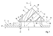
Fig. 2 und3 , jedoch bei weiteren Ausführungsformen, - Fig. 6 und 7
- vereinfachte Schnittansichten im Bereich der Buchse wieder vor dem Verschweißen, jedoch bei anderen Ausführungsformen.
- Entsprechend
Fig. 1 besitzt eine Abgasanlagenkomponente 1, bei der es sich beispielsweise um einen Katalysator handeln kann, zumindest ein Bauteil 2, zum Beispiel ein Gehäuse, an dem zumindest eine Buchse 3 befestigt ist. Die Befestigung der Buchse 3 am Bauteil 2 soll dabei mittels eines Schweißverfahrens realisiert werden, das nachfolgend noch näher beschrieben wird. Das Schweißverfahren ist in den Darstellungen derFig. 1 bis 7 jedoch noch nicht vollendet, so dass in denFig. 1 bis 7 insbesondere keine Schweißstelle oder Schweißnaht erkennbar ist. Eine Position, in der sich besagte Schweißstelle bzw. Schweißverbindung nach Vollendung des Schweißverfahrens befinden soll, ist inFig. 1 mit 4 bezeichnet. - Zur Durchführung des Schweißverfahrens sind das Bauteil 2 und die Buchse 3 aus einem Metall hergestellt. Dabei kann es sich grundsätzlich um unterschiedliche Metalle handeln, solange sie miteinander verschweißbar sind. Gemäß den
Fig. 2 bis 7 wird an der Buchse 3 eine ringförmige Kontaktfläche 5 ausgebildet. Am Bauteil 2 wird eine Bauteilöffnung 6 ausgebildet. Außerdem wird am Bauteil 2 ein entlang der Bauteilöffnung 6 umlaufender Kragen 7 ausgebildet. Der Kragen 7 steht dabei an einer Montageseite 8 des Bauteils 2 vor bzw. ab, die zum Ansetzen der Buchse 3 in einer durch einen Pfeil angedeuteten Ansetzrichtung 9 vorgesehen ist. - Das Ansetzen der Buchse 3 an der Montageseite 8 erfolgt im Wesentlichen zentrisch zur Bauteilöffnung 6, derart, dass die Kontaktfläche 5 den Kragen 7 an dessen Stirnseite oder Endkante berührt, die weiter unten als Kragenfläche 21 bezeichnet wird. Beachtenswert ist in
Fig. 1 , dass in den Details II und III zwei verschiedene Ausführungsformen dargestellt sind, die vergrößert in denFig. 2 und3 wiedergegeben sind. Es ist klar, dass innerhalb einer Schweißverbindung 4 vorzugsweise jeweils nur eine einzige Ausführungsform realisiert wird. - Anschließend wird die Buchse 3 in der Ansetzrichtung 9 gegen das Bauteil 2 angedrückt, derart, dass die Kontaktfläche 5 unter Vorspannung am Kragen 7 anliegt. Dabei kommt es bevorzugt gleichzeitig zu einem weitgehend federelastischen Nachgeben des Kragens 7, wodurch Herstellungstoleranzen, wie z.B. eine in Umfangsrichtung variierende Kragenhöhe 30 und/oder eine in Umfangsrichtung variierende Wandstärke 31 des Kragens 7 und/oder eine von der Kreisform abweichende Umlaufkontur des Kragens 7, ausgeglichen werden, so dass der Kragen 7 im Idealfall in der Umfangsrichtung lückenlos geschlossen an der Kontaktfläche 5 zur Anlage kommt. Während die Kontaktfläche 5 vorgespannt am Kragen 7 anliegt, wird ein Widerstandsschweißen durchgeführt, derart, dass Buchse 3 und Bauteil 2 im Bereich des Kontakts von Kontaktfläche 5 und Kragen 7 miteinander verschweißt werden. Somit wird letztlich die in
Fig. 1 angedeutete ringförmig umlaufende Schweißverbindung 4 erzeugt. - Für das Widerstandsschweißen kommt bevorzugt ein Kondensatorentladungsschweißen zum Einsatz, das sich durch besonders kurze Schweißimpulse auszeichnet.
- Bei den Ausführungsformen der
Fig. 2 ,3 und5-7 ist die Kontaktfläche 5 eben ausgestaltet, so dass sie in einer Kontaktebene 10 liegt. Bei der inFig. 4 gezeigten Ausführungsform ist die Kontaktfläche 5 dagegen konisch ausgestaltet. - Bei allen gezeigten Ausführungsformen besitzt die Buchse 3 eine Durchgangsöffnung 11. Diese ist im montierten Zustand, also bei angeschweißter Buchse 3 an die Bauteilöffnung 6 angeschlossen. Die Durchgangsöffnung 11 ist geradlinig ausgestaltet, so dass sie eine Längsmittelachse 12 der Buchse 3 definiert. Die Durchgangsöffnung 11 ist von einer zylindrischen Wandung 13 eingefasst, die zweckmäßig ein Innengewinde 14 besitzt. Weiterhin weist die Buchse 3 einen Kopplungsbereich 15 auf, der an einer vom Bauteil 2 abgewandten Seite an die Kontaktfläche 5 anschließt und der zum Anbauen eines nur in
Fig. 1 mit unterbrochener Linie angedeuteten Anbauteils 25, wie zum Beispiel eines Sensors, dient. Insbesondere ist dieser Kopplungsbereich 15 durch einen Körper der Buchse 3 gebildet, an dem die Kontaktfläche 5 ausgebildet ist. - Die Kontaktfläche 5 läuft entlang einer Umlaufbahn ringförmig um. Diese Umlaufbahn liegt bei ebener Kontaktfläche 5 in einer Umlaufebene 16. Bei den Ausführungsformen der
Fig. 2 ,3 und5 erstreckt sich die Längsmittelachse 12 senkrecht zur Umlaufebene 16. Im Unterschied dazu zeigen dieFig. 6 und7 Ausführungsbeispiele, bei denen die Längsmittelachse 12 gegenüber dieser Umlaufebene 16 geneigt ist und damit einen Neigungswinkel 17 einschließt, der in den Beispielen derFig. 6 und7 rein exemplarisch bei etwa 45° liegt. Für diesen Neigungswinkel 17 ist ein Winkelbereich von 15° bis 75° vorteilhaft. Bevorzugt ist ein Winkelbereich von 30° bis 60°. Besonders bevorzugt ist ein Winkelbereich von 40° bis 50°. - Gemäß den
Fig. 2 bis 7 besitzt der Kragen 7 einen freistehenden Rand 18, der sich beim Ansetzen der Buchse 3 an einem der Buchse 3 zugewandten Ende des Kragens 7 befindet. Dieser freistehende Rand 18 kann gemäß der inFig. 5 exemplarisch angedeuteten Ausführungsform grundsätzlich abgerundet ausgestaltet sein. Bevorzugt ist jedoch die in denFig. 2 bis 4 ,6 und7 gezeigte Ausführungsform, bei welcher der freistehende Rand 18 eine umlaufende, bezüglich der Bauteilöffnung 6 distale Außenkante 19 und eine umlaufende, bezüglich der Bauteilöffnung 6 proximale Innenkante 20 aufweist. Ferner besitzt der freistehende Rand 18 eine Kragenfläche 21, die radial außen von der Außenkante 19 und radial innen von der Innenkante 20 begrenzt ist. Eine derartige Konstellation lässt sich besonders einfach herstellen, wenn die Bauteilöffnung 6 durch einen Stanzvorgang im Bauteil 2 ausgebildet wird. - Das Bauteil 2 ist dabei zweckmäßig durch einen Umformvorgang, beispielsweise durch Tiefziehen, hergestellt. Anschließend kann die jeweilige Bauteilöffnung 6 beispielsweise durch einen Stanzvorgang ausgebildet werden. Der Kragen 7 kann ebenfalls durch einen Umformvorgang integral am Bauteil 2 ausgeformt werden. Beispielsweise wird hierbei ein die Bauteilöffnung 6 einfassender Öffnungsrand 26 umgeformt, insbesondere ausgestellt. Durch das Tiefziehen des Bauteils 2 und durch die Herstellung des Kragens 7 durch einen Umformvorgang, kann der Kragen 7 eine entlang seiner Umfangsrichtung variierende Wandstärke 31 aufweisen. Ferner kann der freistehende Rand 18 toleranzbedingt bezüglich einer senkrecht zur Axialrichtung der Bauteilöffnung 6 verlaufenden Referenzebene in der Umfangsrichtung schwankende Abstände besitzen, was einer in Umfangsrichtung variierenden Kragenhöhe 30 entspricht. Diese herstellungsbedingten Schwankungen können durch das hier vorgestellte Befestigungsverfahren insbesondere dadurch kompensiert werden, dass der Kragen 7 in der Ansetzrichtung 9 federelastisch ist, so dass beim Andrücken der Buchse 3 an das Bauteil 2 ein optimaler Kontakt zwischen Kontaktfläche 5 und Kragen 7 realisierbar ist, der eine hinreichend hochwertige Schweißverbindung 4 beim Widerstandsschweißen ermöglicht.
- Die zuvor genannte Kragenfläche 21 ist bei den Ausführungsformen der
Fig. 2 und7 eben ausgestaltet, so dass sie in einer Kragenebene 22 liegt. Bei den Ausführungsformen derFig. 3, 4 und6 ist die Kragenfläche 21 dagegen konisch ausgestaltet, so dass sie einen Konus bzw. Kegelmantel bildet. - Bei den Ausführungsformen der
Fig. 2 ,5 und7 ist der Kragen 7 zylindrisch ausgestaltet, so dass er einen Zylindermantel bildet. Im Unterschied dazu ist der Kragen 7 bei den bevorzugten Ausführungsbeispielen derFig. 3, 4 und6 konisch ausgestaltet, so dass er einen Kegelmantel oder Konus bildet. Die konische Ausgestaltung des Kragens 7 erhöht die Federelastizität des Kragens 7 in der Ansetzrichtung 9. - Bei den Ausführungsbeispielen der
Fig. 2 ,3 und5 ist die Buchse 3 mit einem ringförmigen Vorsprung 23 ausgestattet, der von der Kontaktfläche 5 eingefasst ist bzw. darin konzentrisch angeordnet ist. Der Vorsprung 23 geht beim Ansetzen der Buchse 3 voraus und ist so auf die Bauteilöffnung 6 abgestimmt, dass er in die Bauteilöffnung 6 eindringt. Der Vorsprung 23 ist dabei integraler Bestandteil des Buchsenkörpers, der insbesondere durch den Kopplungsbereich 15 gebildet ist. Somit kann sich insbesondere das zuvor genannte Innengewinde 14 bis in den Vorsprung 23 hineinerstrecken. Im Unterschied zu denFig. 2 ,3 und5 ist bei den Ausführungsformen derFig. 4 ,6 und7 kein derartiger Vorsprung 23 vorgesehen. Bei diesen Ausführungsformen bildet die Kontaktfläche 5 das vorausgehende Ende bzw. das dem Bauteil 2 zugewandte Ende der Buchse 3. - Besagter Vorsprung 23 besitzt gemäß den
Fig. 2 ,3 und5 eine Umfangsfläche 24, die der Kontaktfläche 5 zugewandt ist und ringförmig umlaufend ist. Die Umfangsfläche 24 befindet sich somit an der von der Durchgangsöffnung 11 abgewandten Außenseite des Vorsprungs 23. Bei den Ausführungsformen derFig. 2 und3 ist diese Umfangsfläche 23 zylindrisch ausgestaltet, so dass sie einen Zylindermantel bildet. Im Unterschied dazu zeigtFig. 5 eine Ausführungsform, bei der die Umfangsfläche 24 konisch ausgestaltet ist, so dass sie einen Kegelmantel oder Konus bildet. - Grundsätzlich sind die mit Bezug auf die
Fig. 2 bis 7 beschriebenen unterschiedlichen Ausgestaltungen nahezu beliebig miteinander kombinierbar. Als besonders vorteilhaft hat sich jedoch die inFig. 3 gezeigte Ausführungsform herausgestellt. Dort ist der Kragen 7 konisch. Der freistehende Rand 18 weist die Außenkante 19 und die Innenkante 20 auf. Die Buchse 3 besitzt den Vorsprung 23 mit Umfangsfläche 24. Die Umfangsfläche 24 ist zylindrisch. Die Kontaktfläche 5 ist eben. Durch diese Konfiguration ergibt sich beim Andrücken der Buchse 3 zunächst ein axialer Kontakt zwischen der Außenkante 19 und der Kontaktfläche 5. Durch federndes Nachgeben des Kragens 7 kommt es dabei außerdem zu einem radialen Kontakt zwischen der Innenkante 20 und der Umfangsfläche 24. Im nachfolgenden Schweißvorgang lässt sich dadurch eine besonders hochwertige Schweißverbindung 4 realisieren. - Obwohl bei den hier bevorzugten Ausführungsformen eine Buchse 3 zum Einsatz kommt, die keinen Schweißbuckel aufweist, ist grundsätzlich denkbar, das hier vorgestellte Verfahren auch mit einer herkömmlichen Buchse 3 zu realisieren, die einen ringförmigen Schweißbuckel aufweist, der dann die Kontaktfläche 5 aufweist und der mit dem Kragen 7 in Kontakt kommt. Der Kontakt des freistehenden Endes 18 des Kragens 7 kann dabei je nach Konstellation an einer Außenflanke des Schweißbuckels, z.B. über die Innenkante 20, oder an einer Innenflanke des Schweißbuckels, z.B. über die Außenkante 19, oder an einer Stirnseite des Schweißbuckels, z.B. über die stirnseitige Kragenfläche 21, erfolgen.
- Das Bauteil 2 ist vorzugsweise ein Blechformteil und kann zumindest im Bereich der Bauteilöffnung 6 eine Wandstärke 27 aufweisen, die kleiner ist als eine Wandstärke 28 der Buchse 3 in einem die Kontaktfläche 5 aufweisenden Endbereich 29 der Buchse 3. Bei der Buchse 3 handelt es sich vorzugsweise um ein Gussteil. Die Wandstärke 28 der Buchse 3 wird dabei radial zu ihrer Längsmittelachse 12 gemessen. Von diesem Endbereich 29 der Buchse 3 steht beispielsweise der vorstehend genannte Vorsprung 23 axial ab, so dass die Wandstärke 28 der Buchse 3 außerhalb dieses Vorsprungs 23 gemessen ist.
- Bei den hier gezeigten Beispielen erfolgt die Umformung des Öffnungsrands 26 zum Herstellen des Kragens 7 derart, dass sich dabei die Wandstärke nicht wesentlich verändert, so dass der Kragen 7 eine Wandstärke 31 aufweist, die letztlich im Wesentlichen gleich groß ist wie die Wandstärke 27 des Bauteils 2. In anderen Fällen nimmt die Wandstärke beim Umformen ab, so dass die Wandstärke 31 des Kragens 7 dann kleiner ist als die Wandstärke 27 des Bauteils 2.
- Des Weiteren kann vorgesehen sein, dass der Kragen 7 nach seiner Herstellung durch Umfromung des Öffnungsrand 26 eine Höhe 30 aufweist, mit der er über die Montageseite 8 des Bauteils 2 vorsteht. Diese Höhe 30 ist vorzugsweise nun mindestens so groß wie die Wandstärke 27 des Bauteils 2 im Bereich der Bauteilöffnung 6. In den Beispielen der
Fig. 3 und 4 ist die Höhe 30 des Kragens 7 etwa gleich groß wie die Wandstärke 27 des Bauteils 2. In den Beispielen derFig. 2 und5 bis 7 ist die Höhe 30 des Kragens 7 dagegen größer als, vorzugsweise mindestens doppelt so groß wie, die Wandstärke 27 des Bauteils 2 im Bereich der Bauteilöffnung 6.
Claims (15)
- Verfahren zum Befestigen einer metallischen Buchse (3) an einem metallischen Bauteil (2),- bei dem an der Buchse (3) eine ringförmige Kontaktfläche (5) ausgebildet wird,- bei dem an dem Bauteil (2) eine Bauteilöffnung (6) ausgebildet wird,- bei dem am Bauteil (2) ein entlang der Bauteilöffnung (6) umlaufender Kragen (7) durch Umformung eines die Bauteilöffnung (6) einfassenden Öffnungsrands (26) ausgebildet wird, so dass der Kragen (7) an einer Montageseite (8) des Bauteils (2) vorsteht, die zum Ansetzen der Buchse (3) vorgesehen ist,- bei dem die Buchse (3) im Bereich der Bauteilöffnung (6) so an der Montageseite (8) des Bauteils (2) angedrückt wird, dass die Kontaktfläche (5) den Kragen (7) berührt,- bei dem die Buchse (3) gegen das Bauteil (2) angedrückt wird, so dass die Kontaktfläche (5) unter Vorspannung am Kragen (7) anliegt,- bei dem ein Widerstandsschweißen durchgeführt wird, während die Kontaktfläche (5) vorgespannt am Kragen (7) anliegt, so dass Buchse (3) und Bauteil (2) im Bereich des Kontakts von Kontaktfläche (5) und Kragen (7) miteinander verschweißt werden.
- Verfahren nach Anspruch 1,
dadurch gekennzeichnet,
dass das Andrücken der Buchse (3) am Kragen (7) so erfolgt, dass der Kragen (7) weitgehend federelastisch nachgibt, um in der Umfangsrichtung weitgehend geschlossen an der Kontaktfläche (5) zur Anlage zu kommen. - Verfahren nach Anspruch 1 oder 2,
dadurch gekennzeichnet,
dass für das Bauteil (2) zumindest im Bereich der Bauteilöffnung (6) eine Wandstärke (27) gewählt wird, die kleiner ist als eine Wandstärke (28) der Buchse (3) in einem die Kontaktfläche (5) aufweisenden Endbereich (29). - Verfahren nach einem der Ansprüche 1 bis 3,
dadurch gekennzeichnet,
dass der Kragen (7) so geformt wird, dass er mit einer Höhe (30) über die Montageseite (8) vorsteht, die mindestens so groß ist wie oder größer ist als eine Wandstärke (27) des Bauteils (2) im Bereich der Bauteilöffnung (6). - Verfahren nach einem der Ansprüche 1 bis 4,
dadurch gekennzeichnet,
dass die Kontaktfläche (5) eben oder konisch ist. - Verfahren nach einem der Ansprüche 1 bis 5,
dadurch gekennzeichnet,- dass die Buchse (3) eine Durchgangsöffnung (11) aufweist, die im angeschweißten Zustand an die Bauteilöffnung (6) anschließt und die eine Längsmittelachse (12) der Buchse (3) definiert,- dass die Buchse (3) einen Kopplungsbereich (15) aufweist, der an einer vom Bauteil (2) abgewandten Seite an die Kontaktfläche (5) anschließt und zum Anbauen eines Anbauteils (25) dient. - Verfahren nach Anspruch 6,
dadurch gekennzeichnet,- dass eine Umlaufbahn, entlang der die Kontaktfläche (5) ringförmig umläuft, in einer Umlaufebene (16) liegt,- dass sich die Längsmittelachse (12) senkrecht zur Umlaufebene (16) erstreckt. - Verfahren nach Anspruch 6,
dadurch gekennzeichnet,- dass eine Umlaufbahn, entlang der die Kontaktfläche (5) ringförmig umläuft, in einer Umlaufebene (16) liegt,- dass die Längsmittelachse (12) gegenüber der Umlaufebene (16) in einem Winkelbereich von 15° bis 75°, vorzugsweise von 30° bis 60°, insbesondere von 40° bis 50°, geneigt ist. - Verfahren nach einem der Ansprüche 1 bis 8,
dadurch gekennzeichnet,
dass ein freistehender Rand (18) des Kragens (7) vor dem Ansetzen der Buchse (3) abgerundet ist. - Verfahren nach einem der Ansprüche 1 bis 8,
dadurch gekennzeichnet,
dass ein freistehender Rand (18) des Kragens (7) vor dem Ansetzen der Buchse (3) eine umlaufende Kragenfläche (21) aufweist, die von einer umlaufenden, bezüglich der Bauteilöffnung (6) distalen Außenkante (19) und einer umlaufenden, bezüglich der Bauteilöffnung (6) proximalen Innenkante (20) begrenzt ist. - Verfahren nach Anspruch 10,
dadurch gekennzeichnet,- dass die Kragenfläche (21) eben oder konisch ist, und/oder- dass der Kragen (7) zylindrisch oder konisch ist. - Verfahren nach einem der Ansprüche 1 bis 11,
dadurch gekennzeichnet,
dass die Buchse (3) einen ringförmigen Vorsprung (23) aufweist, der von der Kontaktfläche (5) eingefasst ist und der beim Ansetzen der Buchse (3) in die Bauteilöffnung (6) eindringt. - Verfahren nach Anspruch 12,
dadurch gekennzeichnet,
dass der Vorsprung (23) eine umlaufende, der Kontaktfläche (5) zugewandte, ringförmige Umfangsfläche (24) aufweist, die zylindrisch oder konisch ist. - Verfahren nach einem der Ansprüche 1 bis 13,
dadurch gekennzeichnet,- dass der Kragen (7) konisch ist,- dass ein freistehender Rand (18) des Kragens (7) eine bezüglich der Bauteilöffnung (6) distale Außenkante (19) und eine bezüglich der Bauteilöffnung (6) proximale Innenkante (20) aufweist,- dass die Buchse (3) einen ringförmigen Vorsprung (23) aufweist, der von der Kontaktfläche (5) eingefasst ist und der beim Ansetzen der Buchse (3) in die Bauteilöffnung (6) eindringt,- dass der Vorsprung (23) eine umlaufende, der Kontaktfläche (5) zugewandte, ringförmig umlaufende Umfangsfläche (24) aufweist,- dass die Umfangsfläche (24) zylindrisch ist,- dass die Kontaktfläche (5) eben ist,- dass das Andrücken der Buchse (3) so erfolgt, dass die Außenkante (19) an der Kontaktfläche (5) anliegt und die Innenkante (2) an der Umfangsfläche (24) anliegt. - Abgasanlagenkomponente mit wenigstens einem Bauteil (2), an dem wenigstens eine Buchse (3) mit dem Verfahren nach einem der Ansprüche 1 bis 14 befestigt ist.
Applications Claiming Priority (1)
| Application Number | Priority Date | Filing Date | Title |
|---|---|---|---|
| DE102015216013.0A DE102015216013A1 (de) | 2015-08-21 | 2015-08-21 | Befestigungsverfahren für eine Buchse |
Publications (2)
| Publication Number | Publication Date |
|---|---|
| EP3132880A1 true EP3132880A1 (de) | 2017-02-22 |
| EP3132880B1 EP3132880B1 (de) | 2022-07-13 |
Family
ID=56740862
Family Applications (1)
| Application Number | Title | Priority Date | Filing Date |
|---|---|---|---|
| EP16183325.6A Active EP3132880B1 (de) | 2015-08-21 | 2016-08-09 | Befestigungsverfahren für eine buchse |
Country Status (4)
| Country | Link |
|---|---|
| US (1) | US10449623B2 (de) |
| EP (1) | EP3132880B1 (de) |
| CN (1) | CN106468300B (de) |
| DE (1) | DE102015216013A1 (de) |
Cited By (2)
| Publication number | Priority date | Publication date | Assignee | Title |
|---|---|---|---|---|
| ES2775349A1 (es) * | 2019-01-24 | 2020-07-24 | Sodecia Automotive Valencia S L U | Procedimiento y pieza para soldadura |
| US11328525B2 (en) | 2019-09-05 | 2022-05-10 | Beescanning Global Ab | Method for calculating deviation relations of a population |
Families Citing this family (3)
| Publication number | Priority date | Publication date | Assignee | Title |
|---|---|---|---|---|
| DE102016114556A1 (de) | 2016-08-05 | 2018-02-08 | Eberspächer Exhaust Technology GmbH & Co. KG | Verfahren zum Verschweißen zweier Bauteile, vorzugsweise einer Abgasanlage einer Brennkraftmaschine, miteinander durch Widerstandsschweißen |
| DE102018104244A1 (de) * | 2018-02-26 | 2019-08-29 | Eberspächer Exhaust Technology GmbH & Co. KG | Abgasanlage |
| DE102024106105A1 (de) * | 2024-03-04 | 2025-09-04 | Purem GmbH | Sondentragebaugruppe, insbesondere für eine Abgasanlage einer Brennkraftmaschine |
Citations (2)
| Publication number | Priority date | Publication date | Assignee | Title |
|---|---|---|---|---|
| EP0352862A2 (de) * | 1988-07-28 | 1990-01-31 | Koninklijke Emballage Industrie Van Leer B.V. | Behälterverschluss |
| US20060059683A1 (en) * | 2004-07-19 | 2006-03-23 | Catalogna John A | Draw-form for exhaust components and method of manufacture |
Family Cites Families (21)
| Publication number | Priority date | Publication date | Assignee | Title |
|---|---|---|---|---|
| DE969499C (de) * | 1950-09-30 | 1958-06-12 | Luitpoldhuette Ag | Verfahren zum Herstellen von aus Schleuderguss bestehenden, beiderseits mit Flanschen versehenen Rohren |
| CH346739A (fr) * | 1957-03-08 | 1960-05-31 | Huet Andre | Procédé de fixation d'un tube sur une paroi qu'il traverse |
| US2996600A (en) * | 1957-03-28 | 1961-08-15 | Griscom Russell Co | Method of welding tubular heat exchanger parts |
| SE306859B (de) * | 1963-08-21 | 1968-12-09 | R Hiltscher | |
| GB1302371A (de) * | 1969-02-27 | 1973-01-10 | Foster Wheeler Brown Boilers | |
| IT1011357B (it) * | 1973-05-07 | 1977-01-20 | Chemetron Corp | Raccordo tubolare a t |
| DE2434482C3 (de) * | 1974-07-18 | 1981-01-08 | Hans Berg Verwaltungs-Gmbh Und Co, Kg, 5226 Reichshof | Verfahren zur Herstellung eines Anschlußelements für Zu- und Ablaufleitungen von Plattenradiatoren |
| JPS5922900B2 (ja) * | 1976-10-29 | 1984-05-29 | 日本碍子株式会社 | 主として内燃機関よりの排気ガス中の酸素分圧測定装置 |
| JPS60137580A (ja) * | 1983-12-26 | 1985-07-22 | Mazda Motor Corp | 絶縁層を有する鋼板へのナツト溶接方法 |
| FR2621843B1 (fr) * | 1987-10-16 | 1990-03-09 | Framatome Sa | Procede de fixation par soudage d'une tubulure sur un element de paroi de forte epaisseur telle qu'une virole porte-tubulures d'une cuve de reacteur nucleaire |
| JPH08246863A (ja) * | 1995-01-13 | 1996-09-24 | Toyota Motor Corp | 内燃機関の排気管 |
| JPH1026037A (ja) * | 1996-07-09 | 1998-01-27 | Yutaka Giken Co Ltd | センサ取付ボス |
| JP2001340972A (ja) * | 2000-06-02 | 2001-12-11 | Usui Internatl Ind Co Ltd | 高炭素鋼材、高張力低合金鋼材のプロジェクション溶接方法 |
| DE10208872C1 (de) * | 2002-03-01 | 2003-08-07 | Emitec Emissionstechnologie | Verfahren zum Herstellen eines Wabenkörpers, insbesondere für einen Katalysator-Trägerkörper in Abgasreinigungsanlagen von Brennkraftmaschinen, mit einem Flanschstück zur Aufnahme für einen Messfühler und entsprechend hergestellter Wabenkörper |
| DE202004000200U1 (de) * | 2004-01-09 | 2004-04-15 | Heinrich Gillet Gmbh | Gehäuse für Abgasanlagen |
| US7765801B2 (en) * | 2005-11-30 | 2010-08-03 | Benteler Automotive Corporation | Exhaust gas treatment device with insulated housing construction |
| JP2007297985A (ja) * | 2006-05-01 | 2007-11-15 | Yamaha Motor Co Ltd | 排気装置およびその排気装置を備えた車両 |
| JP4850119B2 (ja) * | 2007-04-18 | 2012-01-11 | 川崎重工業株式会社 | 車両の排気装置 |
| US8459004B2 (en) * | 2010-10-26 | 2013-06-11 | Liang Fei Industry Co., Ltd. | Oxygen sensor bung of motor vehicle exhaust pipe |
| US8893471B2 (en) * | 2013-02-28 | 2014-11-25 | Kawasaki Jukogyo Kabushiki Kaisha | Exhaust apparatus for four wheeled utility vehicle |
| US20160237874A1 (en) * | 2015-02-12 | 2016-08-18 | General Electric Company | Catalyst assembly with sensing adapter system |
-
2015
- 2015-08-21 DE DE102015216013.0A patent/DE102015216013A1/de active Pending
-
2016
- 2016-08-09 EP EP16183325.6A patent/EP3132880B1/de active Active
- 2016-08-09 CN CN201610645275.XA patent/CN106468300B/zh active Active
- 2016-08-19 US US15/241,616 patent/US10449623B2/en active Active
Patent Citations (2)
| Publication number | Priority date | Publication date | Assignee | Title |
|---|---|---|---|---|
| EP0352862A2 (de) * | 1988-07-28 | 1990-01-31 | Koninklijke Emballage Industrie Van Leer B.V. | Behälterverschluss |
| US20060059683A1 (en) * | 2004-07-19 | 2006-03-23 | Catalogna John A | Draw-form for exhaust components and method of manufacture |
Cited By (2)
| Publication number | Priority date | Publication date | Assignee | Title |
|---|---|---|---|---|
| ES2775349A1 (es) * | 2019-01-24 | 2020-07-24 | Sodecia Automotive Valencia S L U | Procedimiento y pieza para soldadura |
| US11328525B2 (en) | 2019-09-05 | 2022-05-10 | Beescanning Global Ab | Method for calculating deviation relations of a population |
Also Published As
| Publication number | Publication date |
|---|---|
| CN106468300B (zh) | 2021-06-18 |
| US20170050260A1 (en) | 2017-02-23 |
| US10449623B2 (en) | 2019-10-22 |
| EP3132880B1 (de) | 2022-07-13 |
| DE102015216013A1 (de) | 2017-02-23 |
| CN106468300A (zh) | 2017-03-01 |
Similar Documents
| Publication | Publication Date | Title |
|---|---|---|
| EP3132880B1 (de) | Befestigungsverfahren für eine buchse | |
| EP2980379B2 (de) | Injektionseinrichtung und zugehöriges herstellungsverfahren | |
| DE102010005873B4 (de) | Verfahren zum Verbinden einer Welle und einer Nabe sowie Anordnung aus Welle und Nabe | |
| EP3571431A1 (de) | Ventil | |
| DE102016117149B4 (de) | Zündkerze für Verbrennungsmotor | |
| EP3071828A1 (de) | Anordnung, insbesondere für ein kraftstofffördersystem, und verfahren zu deren herstellung | |
| EP3363064A1 (de) | Batteriepol und elektrische kontakteinheit zur herstellung einer elektrischen verbindung zwischen einem batteriepol und einem bordnetz eines fahrzeugs | |
| EP3779205B1 (de) | Fluidpumpe mit elektrischem antrieb | |
| DE102014114470A1 (de) | Verfahren zum Einbinden eines metallischen flexiblen Leitungselements in eine Fluidleitung und flexibles Leitungselement | |
| DE102015200778A1 (de) | Glühstiftkerze | |
| DE102009013881A1 (de) | Vorrichtung mit einem Beschlag und einer Adapterplatte sowie Verfahren zur Herstellung einer solchen Vorrichtung | |
| DE102017117452A1 (de) | Zündkerze und Verfahren zu ihrer Herstellung | |
| DE102013223721A1 (de) | Zündkerze, insbesondere Wirbelkammerzündkerze | |
| DE102010011739B4 (de) | Zündkerze und Verfahren zur Herstellung einer Zündkerze | |
| EP2915973B1 (de) | Trichter-Rohr-Anordnung | |
| DE102008010192A1 (de) | Verfahren zum Verbinden eines Abgasrohrs mit einem Flansch sowie dadurch hergestellte Flansch-Abgasrohr-Verbindung und Widerstandspressschweißvorrichtung | |
| WO2008071543A1 (de) | HALTERUNGSELEMENT FÜR LAMPENGEFÄßE UND LAMPE MIT HALTERUNGSELEMENT SOWIE VERFAHREN ZUM HALTERN VON LAMPENGEFÄßEN | |
| DE19962311B4 (de) | Katalytische Abgasreinigungsvorrichtung | |
| EP0859437B1 (de) | Verfahren zum Anbringen einer Masseelektrode am Zündkerzenkörper einer Zündkerze | |
| EP2606277B1 (de) | Hochdruck-entladungslampe mit referenzring, und verfahren zur herstellung der hochdruckentladungslampe | |
| EP1385242A1 (de) | Zündkerze | |
| DE19805578C1 (de) | Glühstiftkerze | |
| DE10021809C1 (de) | Fügeverbindung eines Rohres in einem Flansch | |
| AT522335B1 (de) | Steckerbaugruppe zur Verwendung in einem Verbrennungsmotor | |
| DE102008058503A1 (de) | Ladeeinrichtung |
Legal Events
| Date | Code | Title | Description |
|---|---|---|---|
| PUAI | Public reference made under article 153(3) epc to a published international application that has entered the european phase |
Free format text: ORIGINAL CODE: 0009012 |
|
| STAA | Information on the status of an ep patent application or granted ep patent |
Free format text: STATUS: THE APPLICATION HAS BEEN PUBLISHED |
|
| AK | Designated contracting states |
Kind code of ref document: A1 Designated state(s): AL AT BE BG CH CY CZ DE DK EE ES FI FR GB GR HR HU IE IS IT LI LT LU LV MC MK MT NL NO PL PT RO RS SE SI SK SM TR |
|
| AX | Request for extension of the european patent |
Extension state: BA ME |
|
| STAA | Information on the status of an ep patent application or granted ep patent |
Free format text: STATUS: REQUEST FOR EXAMINATION WAS MADE |
|
| 17P | Request for examination filed |
Effective date: 20170802 |
|
| RBV | Designated contracting states (corrected) |
Designated state(s): AL AT BE BG CH CY CZ DE DK EE ES FI FR GB GR HR HU IE IS IT LI LT LU LV MC MK MT NL NO PL PT RO RS SE SI SK SM TR |
|
| STAA | Information on the status of an ep patent application or granted ep patent |
Free format text: STATUS: EXAMINATION IS IN PROGRESS |
|
| 17Q | First examination report despatched |
Effective date: 20190816 |
|
| RAP3 | Party data changed (applicant data changed or rights of an application transferred) |
Owner name: PUREM GMBH |
|
| GRAP | Despatch of communication of intention to grant a patent |
Free format text: ORIGINAL CODE: EPIDOSNIGR1 |
|
| STAA | Information on the status of an ep patent application or granted ep patent |
Free format text: STATUS: GRANT OF PATENT IS INTENDED |
|
| INTG | Intention to grant announced |
Effective date: 20220217 |
|
| GRAS | Grant fee paid |
Free format text: ORIGINAL CODE: EPIDOSNIGR3 |
|
| GRAA | (expected) grant |
Free format text: ORIGINAL CODE: 0009210 |
|
| STAA | Information on the status of an ep patent application or granted ep patent |
Free format text: STATUS: THE PATENT HAS BEEN GRANTED |
|
| AK | Designated contracting states |
Kind code of ref document: B1 Designated state(s): AL AT BE BG CH CY CZ DE DK EE ES FI FR GB GR HR HU IE IS IT LI LT LU LV MC MK MT NL NO PL PT RO RS SE SI SK SM TR |
|
| REG | Reference to a national code |
Ref country code: CH Ref legal event code: EP |
|
| REG | Reference to a national code |
Ref country code: DE Ref legal event code: R096 Ref document number: 502016015060 Country of ref document: DE |
|
| REG | Reference to a national code |
Ref country code: IE Ref legal event code: FG4D Free format text: LANGUAGE OF EP DOCUMENT: GERMAN |
|
| REG | Reference to a national code |
Ref country code: AT Ref legal event code: REF Ref document number: 1504013 Country of ref document: AT Kind code of ref document: T Effective date: 20220815 |
|
| REG | Reference to a national code |
Ref country code: SE Ref legal event code: TRGR |
|
| REG | Reference to a national code |
Ref country code: LT Ref legal event code: MG9D |
|
| REG | Reference to a national code |
Ref country code: NL Ref legal event code: MP Effective date: 20220713 |
|
| PG25 | Lapsed in a contracting state [announced via postgrant information from national office to epo] |
Ref country code: RS Free format text: LAPSE BECAUSE OF FAILURE TO SUBMIT A TRANSLATION OF THE DESCRIPTION OR TO PAY THE FEE WITHIN THE PRESCRIBED TIME-LIMIT Effective date: 20220713 Ref country code: PT Free format text: LAPSE BECAUSE OF FAILURE TO SUBMIT A TRANSLATION OF THE DESCRIPTION OR TO PAY THE FEE WITHIN THE PRESCRIBED TIME-LIMIT Effective date: 20221114 Ref country code: NO Free format text: LAPSE BECAUSE OF FAILURE TO SUBMIT A TRANSLATION OF THE DESCRIPTION OR TO PAY THE FEE WITHIN THE PRESCRIBED TIME-LIMIT Effective date: 20221013 Ref country code: NL Free format text: LAPSE BECAUSE OF FAILURE TO SUBMIT A TRANSLATION OF THE DESCRIPTION OR TO PAY THE FEE WITHIN THE PRESCRIBED TIME-LIMIT Effective date: 20220713 Ref country code: LV Free format text: LAPSE BECAUSE OF FAILURE TO SUBMIT A TRANSLATION OF THE DESCRIPTION OR TO PAY THE FEE WITHIN THE PRESCRIBED TIME-LIMIT Effective date: 20220713 Ref country code: LT Free format text: LAPSE BECAUSE OF FAILURE TO SUBMIT A TRANSLATION OF THE DESCRIPTION OR TO PAY THE FEE WITHIN THE PRESCRIBED TIME-LIMIT Effective date: 20220713 Ref country code: FI Free format text: LAPSE BECAUSE OF FAILURE TO SUBMIT A TRANSLATION OF THE DESCRIPTION OR TO PAY THE FEE WITHIN THE PRESCRIBED TIME-LIMIT Effective date: 20220713 Ref country code: ES Free format text: LAPSE BECAUSE OF FAILURE TO SUBMIT A TRANSLATION OF THE DESCRIPTION OR TO PAY THE FEE WITHIN THE PRESCRIBED TIME-LIMIT Effective date: 20220713 |
|
| PG25 | Lapsed in a contracting state [announced via postgrant information from national office to epo] |
Ref country code: PL Free format text: LAPSE BECAUSE OF FAILURE TO SUBMIT A TRANSLATION OF THE DESCRIPTION OR TO PAY THE FEE WITHIN THE PRESCRIBED TIME-LIMIT Effective date: 20220713 Ref country code: IS Free format text: LAPSE BECAUSE OF FAILURE TO SUBMIT A TRANSLATION OF THE DESCRIPTION OR TO PAY THE FEE WITHIN THE PRESCRIBED TIME-LIMIT Effective date: 20221113 Ref country code: HR Free format text: LAPSE BECAUSE OF FAILURE TO SUBMIT A TRANSLATION OF THE DESCRIPTION OR TO PAY THE FEE WITHIN THE PRESCRIBED TIME-LIMIT Effective date: 20220713 Ref country code: GR Free format text: LAPSE BECAUSE OF FAILURE TO SUBMIT A TRANSLATION OF THE DESCRIPTION OR TO PAY THE FEE WITHIN THE PRESCRIBED TIME-LIMIT Effective date: 20221014 |
|
| REG | Reference to a national code |
Ref country code: CH Ref legal event code: PL |
|
| REG | Reference to a national code |
Ref country code: DE Ref legal event code: R097 Ref document number: 502016015060 Country of ref document: DE |
|
| PG25 | Lapsed in a contracting state [announced via postgrant information from national office to epo] |
Ref country code: SM Free format text: LAPSE BECAUSE OF FAILURE TO SUBMIT A TRANSLATION OF THE DESCRIPTION OR TO PAY THE FEE WITHIN THE PRESCRIBED TIME-LIMIT Effective date: 20220713 Ref country code: RO Free format text: LAPSE BECAUSE OF FAILURE TO SUBMIT A TRANSLATION OF THE DESCRIPTION OR TO PAY THE FEE WITHIN THE PRESCRIBED TIME-LIMIT Effective date: 20220713 Ref country code: MC Free format text: LAPSE BECAUSE OF FAILURE TO SUBMIT A TRANSLATION OF THE DESCRIPTION OR TO PAY THE FEE WITHIN THE PRESCRIBED TIME-LIMIT Effective date: 20220713 Ref country code: LU Free format text: LAPSE BECAUSE OF NON-PAYMENT OF DUE FEES Effective date: 20220809 Ref country code: LI Free format text: LAPSE BECAUSE OF NON-PAYMENT OF DUE FEES Effective date: 20220831 Ref country code: DK Free format text: LAPSE BECAUSE OF FAILURE TO SUBMIT A TRANSLATION OF THE DESCRIPTION OR TO PAY THE FEE WITHIN THE PRESCRIBED TIME-LIMIT Effective date: 20220713 Ref country code: CZ Free format text: LAPSE BECAUSE OF FAILURE TO SUBMIT A TRANSLATION OF THE DESCRIPTION OR TO PAY THE FEE WITHIN THE PRESCRIBED TIME-LIMIT Effective date: 20220713 Ref country code: CH Free format text: LAPSE BECAUSE OF NON-PAYMENT OF DUE FEES Effective date: 20220831 |
|
| REG | Reference to a national code |
Ref country code: BE Ref legal event code: MM Effective date: 20220831 |
|
| PLBE | No opposition filed within time limit |
Free format text: ORIGINAL CODE: 0009261 |
|
| STAA | Information on the status of an ep patent application or granted ep patent |
Free format text: STATUS: NO OPPOSITION FILED WITHIN TIME LIMIT |
|
| PG25 | Lapsed in a contracting state [announced via postgrant information from national office to epo] |
Ref country code: SK Free format text: LAPSE BECAUSE OF FAILURE TO SUBMIT A TRANSLATION OF THE DESCRIPTION OR TO PAY THE FEE WITHIN THE PRESCRIBED TIME-LIMIT Effective date: 20220713 Ref country code: EE Free format text: LAPSE BECAUSE OF FAILURE TO SUBMIT A TRANSLATION OF THE DESCRIPTION OR TO PAY THE FEE WITHIN THE PRESCRIBED TIME-LIMIT Effective date: 20220713 |
|
| 26N | No opposition filed |
Effective date: 20230414 |
|
| PG25 | Lapsed in a contracting state [announced via postgrant information from national office to epo] |
Ref country code: AL Free format text: LAPSE BECAUSE OF FAILURE TO SUBMIT A TRANSLATION OF THE DESCRIPTION OR TO PAY THE FEE WITHIN THE PRESCRIBED TIME-LIMIT Effective date: 20220713 |
|
| PG25 | Lapsed in a contracting state [announced via postgrant information from national office to epo] |
Ref country code: IE Free format text: LAPSE BECAUSE OF NON-PAYMENT OF DUE FEES Effective date: 20220809 |
|
| PG25 | Lapsed in a contracting state [announced via postgrant information from national office to epo] |
Ref country code: SI Free format text: LAPSE BECAUSE OF FAILURE TO SUBMIT A TRANSLATION OF THE DESCRIPTION OR TO PAY THE FEE WITHIN THE PRESCRIBED TIME-LIMIT Effective date: 20220713 |
|
| PG25 | Lapsed in a contracting state [announced via postgrant information from national office to epo] |
Ref country code: BE Free format text: LAPSE BECAUSE OF NON-PAYMENT OF DUE FEES Effective date: 20220831 |
|
| REG | Reference to a national code |
Ref country code: AT Ref legal event code: MM01 Ref document number: 1504013 Country of ref document: AT Kind code of ref document: T Effective date: 20220809 |
|
| PG25 | Lapsed in a contracting state [announced via postgrant information from national office to epo] |
Ref country code: AT Free format text: LAPSE BECAUSE OF NON-PAYMENT OF DUE FEES Effective date: 20220809 |
|
| PG25 | Lapsed in a contracting state [announced via postgrant information from national office to epo] |
Ref country code: IT Free format text: LAPSE BECAUSE OF FAILURE TO SUBMIT A TRANSLATION OF THE DESCRIPTION OR TO PAY THE FEE WITHIN THE PRESCRIBED TIME-LIMIT Effective date: 20220713 |
|
| PG25 | Lapsed in a contracting state [announced via postgrant information from national office to epo] |
Ref country code: HU Free format text: LAPSE BECAUSE OF FAILURE TO SUBMIT A TRANSLATION OF THE DESCRIPTION OR TO PAY THE FEE WITHIN THE PRESCRIBED TIME-LIMIT; INVALID AB INITIO Effective date: 20160809 |
|
| PG25 | Lapsed in a contracting state [announced via postgrant information from national office to epo] |
Ref country code: CY Free format text: LAPSE BECAUSE OF FAILURE TO SUBMIT A TRANSLATION OF THE DESCRIPTION OR TO PAY THE FEE WITHIN THE PRESCRIBED TIME-LIMIT Effective date: 20220713 |
|
| PG25 | Lapsed in a contracting state [announced via postgrant information from national office to epo] |
Ref country code: SE Free format text: LAPSE BECAUSE OF NON-PAYMENT OF DUE FEES Effective date: 20230810 Ref country code: MK Free format text: LAPSE BECAUSE OF FAILURE TO SUBMIT A TRANSLATION OF THE DESCRIPTION OR TO PAY THE FEE WITHIN THE PRESCRIBED TIME-LIMIT Effective date: 20220713 |
|
| PG25 | Lapsed in a contracting state [announced via postgrant information from national office to epo] |
Ref country code: TR Free format text: LAPSE BECAUSE OF FAILURE TO SUBMIT A TRANSLATION OF THE DESCRIPTION OR TO PAY THE FEE WITHIN THE PRESCRIBED TIME-LIMIT Effective date: 20220713 |
|
| PGFP | Annual fee paid to national office [announced via postgrant information from national office to epo] |
Ref country code: SE Payment date: 20220825 Year of fee payment: 7 |
|
| PG25 | Lapsed in a contracting state [announced via postgrant information from national office to epo] |
Ref country code: BG Free format text: LAPSE BECAUSE OF FAILURE TO SUBMIT A TRANSLATION OF THE DESCRIPTION OR TO PAY THE FEE WITHIN THE PRESCRIBED TIME-LIMIT Effective date: 20220713 |
|
| PG25 | Lapsed in a contracting state [announced via postgrant information from national office to epo] |
Ref country code: MT Free format text: LAPSE BECAUSE OF FAILURE TO SUBMIT A TRANSLATION OF THE DESCRIPTION OR TO PAY THE FEE WITHIN THE PRESCRIBED TIME-LIMIT Effective date: 20220713 |
|
| PGFP | Annual fee paid to national office [announced via postgrant information from national office to epo] |
Ref country code: DE Payment date: 20250819 Year of fee payment: 10 |
|
| PGFP | Annual fee paid to national office [announced via postgrant information from national office to epo] |
Ref country code: GB Payment date: 20250822 Year of fee payment: 10 |
|
| PGFP | Annual fee paid to national office [announced via postgrant information from national office to epo] |
Ref country code: FR Payment date: 20250821 Year of fee payment: 10 |