EP3130889B1 - Télémètre optique - Google Patents
Télémètre optique Download PDFInfo
- Publication number
- EP3130889B1 EP3130889B1 EP16187158.7A EP16187158A EP3130889B1 EP 3130889 B1 EP3130889 B1 EP 3130889B1 EP 16187158 A EP16187158 A EP 16187158A EP 3130889 B1 EP3130889 B1 EP 3130889B1
- Authority
- EP
- European Patent Office
- Prior art keywords
- pixels
- measuring device
- distance
- target object
- spads
- Prior art date
- Legal status (The legal status is an assumption and is not a legal conclusion. Google has not performed a legal analysis and makes no representation as to the accuracy of the status listed.)
- Active
Links
- 230000003287 optical effect Effects 0.000 title claims description 41
- 238000001514 detection method Methods 0.000 claims description 102
- 230000005855 radiation Effects 0.000 claims description 57
- 238000011156 evaluation Methods 0.000 claims description 42
- 238000005259 measurement Methods 0.000 claims description 36
- 230000001419 dependent effect Effects 0.000 claims description 7
- 230000000063 preceeding effect Effects 0.000 claims 1
- 230000008901 benefit Effects 0.000 description 9
- 238000010521 absorption reaction Methods 0.000 description 6
- 238000003384 imaging method Methods 0.000 description 5
- 230000002829 reductive effect Effects 0.000 description 5
- 238000005457 optimization Methods 0.000 description 4
- 230000002123 temporal effect Effects 0.000 description 4
- 230000005540 biological transmission Effects 0.000 description 3
- 230000007423 decrease Effects 0.000 description 3
- 238000005516 engineering process Methods 0.000 description 3
- 238000012935 Averaging Methods 0.000 description 2
- 230000004075 alteration Effects 0.000 description 2
- 230000015556 catabolic process Effects 0.000 description 2
- 239000002800 charge carrier Substances 0.000 description 2
- 238000013461 design Methods 0.000 description 2
- 238000004519 manufacturing process Methods 0.000 description 2
- 230000004044 response Effects 0.000 description 2
- 230000002441 reversible effect Effects 0.000 description 2
- 230000006978 adaptation Effects 0.000 description 1
- 238000013459 approach Methods 0.000 description 1
- 230000008859 change Effects 0.000 description 1
- 238000005352 clarification Methods 0.000 description 1
- 238000010276 construction Methods 0.000 description 1
- 238000012937 correction Methods 0.000 description 1
- 238000013016 damping Methods 0.000 description 1
- 230000003247 decreasing effect Effects 0.000 description 1
- 238000010586 diagram Methods 0.000 description 1
- 230000005684 electric field Effects 0.000 description 1
- 230000005284 excitation Effects 0.000 description 1
- 230000006872 improvement Effects 0.000 description 1
- 230000007246 mechanism Effects 0.000 description 1
- 238000000034 method Methods 0.000 description 1
- 230000003278 mimic effect Effects 0.000 description 1
- 238000001208 nuclear magnetic resonance pulse sequence Methods 0.000 description 1
- 230000005693 optoelectronics Effects 0.000 description 1
- 230000036961 partial effect Effects 0.000 description 1
- 230000000737 periodic effect Effects 0.000 description 1
- 230000010363 phase shift Effects 0.000 description 1
- 238000012545 processing Methods 0.000 description 1
- 238000011084 recovery Methods 0.000 description 1
- 230000009467 reduction Effects 0.000 description 1
- 239000004065 semiconductor Substances 0.000 description 1
- 230000035945 sensitivity Effects 0.000 description 1
- 238000004904 shortening Methods 0.000 description 1
- 239000007787 solid Substances 0.000 description 1
- 230000036962 time dependent Effects 0.000 description 1
- 230000001960 triggered effect Effects 0.000 description 1
Images

Classifications
-
- G—PHYSICS
- G01—MEASURING; TESTING
- G01C—MEASURING DISTANCES, LEVELS OR BEARINGS; SURVEYING; NAVIGATION; GYROSCOPIC INSTRUMENTS; PHOTOGRAMMETRY OR VIDEOGRAMMETRY
- G01C3/00—Measuring distances in line of sight; Optical rangefinders
- G01C3/02—Details
- G01C3/06—Use of electric means to obtain final indication
- G01C3/08—Use of electric radiation detectors
-
- G—PHYSICS
- G01—MEASURING; TESTING
- G01C—MEASURING DISTANCES, LEVELS OR BEARINGS; SURVEYING; NAVIGATION; GYROSCOPIC INSTRUMENTS; PHOTOGRAMMETRY OR VIDEOGRAMMETRY
- G01C15/00—Surveying instruments or accessories not provided for in groups G01C1/00 - G01C13/00
- G01C15/002—Active optical surveying means
-
- G—PHYSICS
- G01—MEASURING; TESTING
- G01S—RADIO DIRECTION-FINDING; RADIO NAVIGATION; DETERMINING DISTANCE OR VELOCITY BY USE OF RADIO WAVES; LOCATING OR PRESENCE-DETECTING BY USE OF THE REFLECTION OR RERADIATION OF RADIO WAVES; ANALOGOUS ARRANGEMENTS USING OTHER WAVES
- G01S17/00—Systems using the reflection or reradiation of electromagnetic waves other than radio waves, e.g. lidar systems
- G01S17/02—Systems using the reflection of electromagnetic waves other than radio waves
- G01S17/06—Systems determining position data of a target
- G01S17/08—Systems determining position data of a target for measuring distance only
- G01S17/10—Systems determining position data of a target for measuring distance only using transmission of interrupted, pulse-modulated waves
-
- G—PHYSICS
- G01—MEASURING; TESTING
- G01S—RADIO DIRECTION-FINDING; RADIO NAVIGATION; DETERMINING DISTANCE OR VELOCITY BY USE OF RADIO WAVES; LOCATING OR PRESENCE-DETECTING BY USE OF THE REFLECTION OR RERADIATION OF RADIO WAVES; ANALOGOUS ARRANGEMENTS USING OTHER WAVES
- G01S17/00—Systems using the reflection or reradiation of electromagnetic waves other than radio waves, e.g. lidar systems
- G01S17/88—Lidar systems specially adapted for specific applications
- G01S17/89—Lidar systems specially adapted for specific applications for mapping or imaging
-
- G—PHYSICS
- G01—MEASURING; TESTING
- G01S—RADIO DIRECTION-FINDING; RADIO NAVIGATION; DETERMINING DISTANCE OR VELOCITY BY USE OF RADIO WAVES; LOCATING OR PRESENCE-DETECTING BY USE OF THE REFLECTION OR RERADIATION OF RADIO WAVES; ANALOGOUS ARRANGEMENTS USING OTHER WAVES
- G01S7/00—Details of systems according to groups G01S13/00, G01S15/00, G01S17/00
- G01S7/48—Details of systems according to groups G01S13/00, G01S15/00, G01S17/00 of systems according to group G01S17/00
- G01S7/481—Constructional features, e.g. arrangements of optical elements
- G01S7/4816—Constructional features, e.g. arrangements of optical elements of receivers alone
-
- G—PHYSICS
- G01—MEASURING; TESTING
- G01S—RADIO DIRECTION-FINDING; RADIO NAVIGATION; DETERMINING DISTANCE OR VELOCITY BY USE OF RADIO WAVES; LOCATING OR PRESENCE-DETECTING BY USE OF THE REFLECTION OR RERADIATION OF RADIO WAVES; ANALOGOUS ARRANGEMENTS USING OTHER WAVES
- G01S7/00—Details of systems according to groups G01S13/00, G01S15/00, G01S17/00
- G01S7/48—Details of systems according to groups G01S13/00, G01S15/00, G01S17/00 of systems according to group G01S17/00
- G01S7/483—Details of pulse systems
- G01S7/486—Receivers
- G01S7/4861—Circuits for detection, sampling, integration or read-out
-
- G—PHYSICS
- G01—MEASURING; TESTING
- G01S—RADIO DIRECTION-FINDING; RADIO NAVIGATION; DETERMINING DISTANCE OR VELOCITY BY USE OF RADIO WAVES; LOCATING OR PRESENCE-DETECTING BY USE OF THE REFLECTION OR RERADIATION OF RADIO WAVES; ANALOGOUS ARRANGEMENTS USING OTHER WAVES
- G01S7/00—Details of systems according to groups G01S13/00, G01S15/00, G01S17/00
- G01S7/48—Details of systems according to groups G01S13/00, G01S15/00, G01S17/00 of systems according to group G01S17/00
- G01S7/491—Details of non-pulse systems
- G01S7/4912—Receivers
- G01S7/4913—Circuits for detection, sampling, integration or read-out
Definitions
- the invention relates to a measuring device for measuring a distance between the measuring device and a target object with the aid of optical measuring radiation.
- Optical distance measuring devices which align a time-modulated light beam in the direction of a target object whose distance from the measuring device is to be determined.
- the returning light reflected or scattered by the targeted target object is at least partially detected by the device and used to determine the distance to be measured.
- a typical measuring range is in a range of distances of a few centimeters to several 100 meters.
- the light beam is, for example, time-modulated in its intensity.
- light pulses can be emitted and a transit time of a light pulse can be measured from the emission to the detection and from this the distance to the target object can be calculated.
- very short light pulses must be sent out and a very fast detection electronics are used in order to obtain sufficiently accurate measurement results.
- a light beam in its intensity can be periodically modulated in time and a phase shift be used between the emitted and the detected light signal to determine the transit time and thus the distance to the target object.
- the principle of laser distance measurement is generally known by the term "time of flight ranging", for example with continuous modulation of the intensity of the laser beam.
- 3D cameras are known in which, in addition to an optical image of an object to be recorded, the respective distance of an area on the surface of the object to be photographed to the camera is to be detected.
- the camera has imaging optics which project an image of the object sharply onto a surface of a detector arranged behind it.
- the detector has a plurality of matrix-like arranged pixels. Each of the pixels can thereby determine image information such as, for example, a color or light intensity of the light reflected from a surface region of the target object.
- information about a distance between the camera and the corresponding surface area of the target object can be obtained.
- the target object can be illuminated with time-modulated laser radiation and the radiation reflected back from the target object and imaged on the detector by means of imaging optics can be used to determine spatially resolved information about distances to the respective surface regions of the target object.
- rangefinders are merely used to determine a distance between the meter and the target object or a laser beam targeted point on the target object.
- the distance need not be determined spatially resolved. It is usually sufficient to determine an average distance.
- Such rangefinders are often used in handheld devices to determine, for example within a room, the distance of a particular location to surrounding targets such as walls or furnishings.
- a hand-held distance measuring device should preferably have the simplest possible, robust and cost-effective design and allow easy operation. From the DE 10 2006 013 290 A1 a device for optical distance measurement is known in which a detector of a receiving unit has a plurality of separate photosensitive surfaces which are activated separately from each other.
- Each of the photosensitive surfaces has a photodiode, for example a PIN diode or an APD (Avalanche Photo Diode), or a CCD chip as a photosensitive element.
- These photosensitive elements detect an analog detection signal corresponding to an intensity of the received light.
- the light-sensitive surfaces can be selectively activated and combined in this way into a total detection surface, which can be adapted as well as possible to a portion of the detector surface illuminated by a light source, in order thus to improve a signal-to-noise ratio.
- the conventional distance measuring device described uses photosensitive elements such as PIN diodes or APDs (Avalanche Photo Diode), which provide an analog measurement signal with high bandwidth, it may be necessary to use a complicated evaluation for the evaluation of these analog measurement signals.
- the analog operating Photosensitive elements are often incompatible with CMOS technology otherwise used in the meter.
- US Pat. No. 7301608 B1 discloses a rangefinder with Geiger Mode Avalanche Photodiodes (SPADs), where the distance to the target is determined based on a set of avalanche events.
- SPADs Geiger Mode Avalanche Photodiodes
- an optical distance measurement measuring apparatus which, particularly in comparison to the conventional distance measuring apparatuses described above, has a simplified structure of electronic components used therein, in particular of evaluation components for the evaluation of detection signals, permits. Further, there may be a need for a rangefinder that can be fabricated largely with a single manufacturing technology, such as CMOS technology.
- the measuring device for optical distance measurement has a transmitting device for emitting optical measuring radiation toward a target object, a receiving device having a detection surface for detecting optical measuring radiation returning from the target object and an evaluation device.
- the detection surface of the receiving device in this case has a multiplicity of pixels, each pixel having at least one SPAD (single photon avalanche diode).
- Each of the plurality of pixels is connected to the evaluation device directly or indirectly via further intermediate components.
- the transmitting device and the receiving device are designed in such a way that optical measuring radiation returning from the target object illuminates a plurality of pixels at the same time when the distance measuring device is used as intended.
- the evaluation device is designed to provide a distance between the measuring device and the target object based on an evaluation of Detecting signals of multiple pixels, in particular several of the simultaneously illuminated pixels to determine. At least a few pixels each contain a plurality of SPADS.
- the transmitting device may be a light source, for example in the form of an LED, a laser or a laser diode, which emits light modulated in time to the target object. The temporal modulation can take place continuously and / or periodically, for example sinusoidally. Pulse trains, for example non-periodic, such as in the form of so-called pseudo-noise pulse sequences can be sent.
- the receiving device may be different from receiving devices as used in conventional rangefinders in that, instead of analogously operating photosensitive elements, which may optionally be interconnected to provide a total analog signal, a plurality of pixels may be provided within a detection area, each Pixel contains one or more SPADs.
- a SPAD is a photosensitive element that delivers a digital detection signal as a function of an incident light intensity.
- Each of the pixels can be connected to the evaluation device directly or, for example, with the interposition of a multiplexer which is designed to selectively transmit detection signals of several pixels. In this way it can be achieved, for example, that detection signals of individual pixels or of a group of pixels can be evaluated by the evaluation device independently of detection signals of other pixels.
- the transmitting device and the receiving device are designed and matched to one another such that optical measuring radiation returning from the target object is illuminated simultaneously under normal measuring conditions, that is, for example at measuring distances of a few centimeters to a few hundred meters.
- a plurality of pixels are illuminated simultaneously is not intended to be used as in conventional 3D cameras be to capture an image of the target object or a spatial resolution with respect to the distance to individual sub-areas on a surface of the target object, but should, as explained below in more detail, inter alia, allow advantages in terms of a detection sensitivity and / or an adjustment tolerance.
- the distance between the measuring device and the target object is determined based on an evaluation of detection signals of a plurality of pixels, in particular a plurality of simultaneously illuminated pixels.
- the transmitting device can emit a measuring beam whose cross-section is sufficiently large that the portion of the measuring beam returning from the target object always illuminates a plurality of pixels.
- a simple optical system for example in the form of one or more lenses, can be provided within the optical path from the transmitting device to the receiving device , be provided. This simple optics can be designed to save costs and reduce costs as a non-automatic focusing optics ("fixed focus").
- the number of pixels illuminated simultaneously by measuring radiation returning from the target object may vary depending on a distance between the target object and the measuring object.
- the optimization of the optical receiving system for the reception of measuring radiation from distant targets with a large object distance can mean that focal length and image distance are to be selected such that the geometric imaging condition is achieved for the large object distance.
- the smallest spot diameter in the image plane can be achieved ("the image is sharp").
- the focal length and image plane By defining the focal length and image plane, the number of pixels that are illuminated in the case of a closer target object can be significantly larger than with a distant target object. With a closer target object, the returning measuring radiation can no longer be sharply imaged, so that the illuminated area of the detection area can be correspondingly larger.
- the receiving device and the evaluation device can be designed for a distance between the measuring device and the target object based on an evaluation of detection signals exclusively of pixels, to the light of the surface illuminated by the transmitting device of the target object is returned to determine.
- the evaluation device can first determine, for example, in a preliminary measurement, which of the pixels of the detection surface actually receive measuring radiation of the transmitting device and which pixels only detect background radiation, and can subsequently use only the detection signals of the pixels illuminated by the measuring radiation for the actual distance determination. As a result, a signal-to-noise ratio can be increased considerably.
- the evaluation device can have at least one distance determining device (sometimes also known as a "binning scheme").
- the distance determination device can be designed to determine a flight duration of measurement radiation between a transmission from the transmission device to a detection of the measurement radiation returning from the target object on the detection surface and to determine therefrom a distance.
- the distance determination device can compare information provided by the transmitting device about the temporal modulation of emitted measuring radiation with detection signals provided by the receiving device. In the case of a periodically modulated emitted measuring radiation, for example, a corresponding distance can be determined from a phase difference between a transmission signal and a detection signal.
- a single distance determination device can suffice for determining a distance between the measuring device and the target object.
- the detection signals of individual pixels or a group of pixels may be successively sent to a distance-determining device, for example by means of a multiplexer to lead. Due to such a sequential processing of detection signals, it can lead to an extension of a total measurement duration.
- each of the pixels can be assigned its own distance determination device. In this case, a distance can be determined from each of the detection signals of the plurality of pixels, possibly temporally parallel to one another, and from the plurality of determined distances finally, for example, by averaging a finally determined distance between the device and the target object can be determined.
- a plurality of pixels may be connected to a distance-determining device, and the distance-determining device may be configured to determine the distance based on detection signals of the plurality of pixels.
- the evaluation device can have a plurality of distance determination devices and can be designed to determine the distance between the measurement device and the target object based on the distances determined by the distance determination devices, for example by averaging.
- a SPAD may have the property of not providing a detection signal which is linearly dependent on the incident radiation, as conventional analog light-sensitive elements do, but producing a single signal with each incident photon.
- the SPAD is not reactivated after the impact of a photon for a certain dead time, which may range from, for example, 1 to 100 ns.
- a certain dead time which may range from, for example, 1 to 100 ns.
- the count rate with which a SPAD can count impinging photons is thus limited upwards by the dead time.
- the combiner can be designed, for example, in the form of an OR gate or in the form of a bus.
- a pulse shortener may be disposed between a SPAD and a combiner or bus to temporally shorten a digital signal generated by the SPAD, thereby enabling a shortened overall dead time and an increased photon counting rate of the system.
- the number of SPADs or the area of SPADs contained in a pixel may be variably selected depending on the location of the pixel within the detection area of the receiving device. For example, it may be known that the measuring radiation returning from the target object can impinge on the detection surface of the receiving device depending on the distance of the target object from the measuring device at a different position and / or with a different cross-sectional area.
- the number or area of SPADs within a pixel can therefore be adapted to the expected incident light intensity depending on the location.
- the returning measuring radiation with a small spotlight can be used for distant target objects.
- Diameter to be focused within such a region of the detection surface, it may be advantageous for each of the pixels to contain only a single SPAD or only a few SPADs. If target objects approaching closer to such a fix-focus measuring device are targeted, the returning measuring radiation on the detection surface can not be focused as a small spot, but possibly defocused, strikes a larger partial area of the detection surface. Overall, in this case, more pixels are illuminated than in the case of a distant target object. It may therefore be advantageous to combine in each case a plurality of SPADs into a single pixel (or "sub-array" or "cluster” of SPADs) in edge regions of the illuminated subarea of the detection surface.
- the transmitting device and the receiving device can be arranged side by side along a parallax axis.
- Such so-called biaxial measuring systems can have the advantage that no elaborate radiation division is necessary for the selection of the returning measuring beam.
- the measuring beam emitted by the transmitting device and returning from the target object can hit the detection surface at a different location along the parallax axis and have different cross sections.
- the transmitting device and the receiving device can be arranged coaxially with one another.
- a monoaxial measuring device it can be achieved, for example with the aid of semitransparent mirrors, that the center of the area of the detection surface illuminated by the returning radiation remains largely position-independent, independently of the distance of the target object.
- the cross-section of the illuminated area on the detection surface may still depend on the distance of the target object.
- distant targets and a wide-focussed lens a small illuminated spot may result, with closer targets to a larger illuminated spot. It may be advantageous to make the number of SPADs contained in a pixel smaller in pixels near the center of the detection area than in pixels away from the center of the detection area.
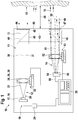
- FIG. 1 schematically a measuring device 10 according to the invention for optical distance measurement with the most important components to describe their function is shown.
- the measuring device 10 has a housing 11, in which a transmitting device 12 for emitting optical measuring radiation 13 and a receiving device 14 for detecting returning from a target object 15 measuring radiation 16 are arranged.
- the transmitting device 12 includes a light source, which is realized by a semiconductor laser diode 18 in the illustrated embodiment.
- the laser diode 18 emits a laser beam 20 in the form of a light beam 22 visible to the human eye.
- the laser diode 18 is operated via a control unit 24, which by a corresponding electronics generates a temporal modulation of an electrical input signal 19 of the laser diode 18.
- a modulation of the diode current it is possible to achieve that the optical measuring radiation 13, which is used for measuring the distance, is likewise modulated in its intensity in the desired manner over time.
- the laser beam 20 then passes through a collimating lens 26 in the form of a lens 28, which in Fig. 1 represented in a simplified manner in the form of a single lens.
- the objective 28 is optionally located on an adjustment mimic 32, which in principle makes it possible to change the position of the objective in all three spatial directions, for example for adjustment purposes.
- the collimating optics 26 may also already be part of the laser diode 18 or be permanently connected thereto.
- an amplitude-modulated signal, for example, of the measuring radiation 13 results in the form of a nearly parallel light bundle 37 which propagates along an optical axis 38 of the transmitting unit 12.
- the transmitting device 12 may also be a preferably switchable beam deflection 40 are located, which allows the measuring radiation 13 completely or partially bypassing the target object 15 directly, that is, device internally to redirect to the receiving device 14. In this way, a device-internal reference path 42 can be generated, which allows a calibration or a comparison of the measuring device.
- the measuring radiation 13 leaves the housing 11 of the measuring device through an optical window 44 in the end wall 45 of the measuring device 10.
- the opening of the optical window 44 can be secured, for example, by a shutter 46.
- the measuring device 10 is then aligned with a target object 15 whose distance 48 to the measuring device 10 is to be determined.
- the signal 16 reflected or scattered at the desired target object 15 forms returning optical Measuring radiation 16 in the form of a returning beam 49 and 50, which comes back to a certain extent back into the measuring device 10.
- the returning measuring radiation 16 is coupled into the measuring device 10 and then hits, as in Fig. 1 shown on a receiving optics 52nd
- Fig. 1 By way of example, two returning measuring beams 49 and 50 for two different target distances 48 are shown for clarification.
- the optical measuring radiation 16 returning from the target object 15 falls approximately parallel to the optical axis 51 of the receiving device 14. This case is in the embodiment of Fig. 1 represented by the measuring beam 49.
- the returning measuring radiation 16 incident in the measuring device is inclined more and more with respect to the optical axis 51 of the receiving device 14 due to a parallax.
- a returning measuring beam in the vicinity of the measuring device is in Fig. 1 the beam 50 drawn.
- the receiving optics 52 which are in Fig. 1 is also symbolized only schematically by a single lens, the beam focuses the returning measuring radiation 16 on the detection surface 66 of a receiving device 14 provided in the receiving detector 54.
- the detector 54 has for detecting the optical measuring radiation on a plurality of pixels. Each of the pixels has at least one photosensitive SPAD.
- the SPADs provided in the detection surface 66 which are arranged individually or in groups in pixels matrix-like and connected to an evaluation device 36, the incident returning measuring radiation 16 is converted into an electrical signal 55 and supplied to the further evaluation in the evaluation device 36 ,
- the electrical signal 55 can be regarded as a digital signal due to inherent properties of the SPADs, which represents a count rate of incident on the respective pixels of the detection surface 66 photons.
- the detection signals generated by a single SPAD or a combination of SPADs can be supplied to one or more distance determination devices (s) contained in an evaluation device 36.
- the distance determination device can add up the detection signals and generate therefrom a signal which corresponds to a time-dependent intensity of the light signal incident on the respective SPAD or the light intensity.
- This signal in relation to an excitation signal which indicates the time profile of the photon rate emitted by the transmitting device, it is possible to deduce a photon flight time from the transmitting device to the target object and back again to the receiving device.
- the transmitting device for example, periodically modulates the emitted light in a sinusoidal manner, a time of flight can be determined from a phase difference between the emitted and the detected measuring radiation.
- single photon avalanche diode sometimes referred to as a single photon avalanche diode, Geiger mode avalanche photodiode or G-APD
- SPAD single photon avalanche diode
- G-APD Geiger mode avalanche photodiode
- a fundamental difference between a SPAD and a conventional avalanche photodiode may be that the SPAD may be specifically designed to operate at a bias in the reverse direction that is above the breakdown voltage of the diode.
- This mode of operation is also called Geiger mode, in analogy to a Geiger counter.
- the electric field within the pn junction may be so strong that a single charge carrier injected into the depletion zone may initiate a self-sustaining avalanche current.
- the current may increase to a macroscopic level, for example in the range of mA, within a period of less than 1 ns.
- the current may be maintained until the avalanche is quenched by lowering the bias to a level below the breakdown voltage, thus breaking off the avalanche current.
- a simple damping circuit may consist of a simple resistor connected in series with the SPAD. The avalanche current is simply damped even due to the resulting voltage drop across the high-impedance series resistor.
- SPAD After the avalanche current has been damped, SPAD recovers and the SPAD is again able to fire again. However, while the avalanche current is flowing and during dampening and subsequent recovery of the bias, the SPAD may not be able to detect additional photons during a dead time ⁇ .
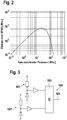
- the count rate determined by a single SPAD at a low rate of photons absorbed may be approximately proportional to the photon absorption rate.
- the count rate starts to saturate at a photon absorption rate slightly less than the inverse dead time 1 / ⁇ .
- the count rate even decreases until it completely collapses above a photon absorption rate, for example, in the range above 10 2 MHz, since at such high photon absorption rates, the SPAD is already triggered again before the voltage has fully recovered, and thus no interruption of the avalanche current can come.
- the efficiency of a paralyzable detector such as a SPAD thus decreases sharply at high photon currents as soon as the photon rate absorbed by the SPAD becomes large compared to an inverse dead time of the SPAD.
- the maximum detectable intensity (power per area) or the maximum detectable photon current or photon rate results in an upper limit for the maximum detectable intensity (power per area) or the maximum detectable photon current or photon rate.
- the photon rate absorbed per detector can be lowered by distributing the light output over several SPADs.
- the detection efficiency at high light outputs, as they can occur especially at short measurement distances, can be improved.
- the light output can be understood as meaning the entire light output detected by the receiving lens of the measuring radiation returning from the target object.
- Fig. 3 shows two SPADs 101, 101 ', whose detection signals are each forwarded to an OR gate 103.
- the OR gate 103 acts as a combiner 104 by receiving both detection signals from the first SPAD 101 and detection signals from the second SPAD 101 'and outputs at output 105 a combined signal of these input signals.
- the situation may be more complicated when using a combiner that combines the detection signals of several individual SPADs on a bus.
- the dead time attributable to the bus can result in additional efficiency losses compared to a fully parallel evaluation of a set of SPADs.
- a possible connection shows Fig. 4 ,
- the event rate 106 on the bus is represented in terms of a rate 107-1, 107-2, 107-3 of absorbed photons in three SPADs.
- the dead time ⁇ 1 of a SPAD is in each case 50 ns
- the dead time ⁇ 2 of the bus is 10 ns. It will be appreciated, for example, that the absorption event 108 of a photon by the second SPAD on the bus is not output as a separate count signal because it falls within the dead time ⁇ 2 of the bus.
- an effective dead time of an entire system consisting of a plurality of SPADs connected to a bus can be shortened.
- the effective dead time of the overall system results from a combination of the dead time of the individual SPADs and the duration of the signals shortened by the shorteners.
- the count rates on the bus are exemplified as a function of a rate of absorbed photons per pixel for a combination of one, four, nine, and sixteen SPADs, respectively.
- the SPAD dead time ⁇ 1 is 50 ns
- the bus dead time ⁇ 2 is 10 ns. Due to the deadtime of the bus, the maximum of the family of curves strives with increasing number of combined SPADs against a limit value (inverse bus dead time). It becomes clear that the dead time of the bus or of the combiner represents an optimization variable. In general, such a bus dead time may be significantly less than the dead time of a SPAD, so combining SPAD detection signals may result in count rates that are higher than the count rates of a single SPAD. Without a combiner or a bus, these higher count rates can only be realized by completely parallel evaluation with additional distance determination devices.
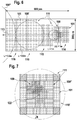
- Fig. 6 schematically shows a detection surface 110 of a detection device 54 for a laser distance measuring device with uncorrected parallax.
- circular laser spots 109 or laser spots the diameter of which varies as a function of a distance L between the measuring device and the target object, are indicated on the detection surface 110.
- the laser radiation was assumed to be at a divergence of 1 mrad.
- the parallax axis is here assumed to be the intersection line between a detection surface plane and a plane spanned by the optical axis of the receiving optics and the laser beam axis of the distance measuring device. It can be seen that in a first region 114 in which the laser spot 109 is incident, when the laser beam is reflected back from a distant target, small pixels are provided, each containing only a single SPAD.
- the laser spot 109 In a region 115 in which the laser spot 109 'impinges when the target is about 0.5 to 1 m away, larger pixels are provided with four SPADs each. In a further region 116, in which the laser spot 109 "impinges in the case of very close target objects, particularly large pixels with 8 or 16 SPADs are provided, the receiving optics being optimized so that the best possible imaging quality, ie the smallest possible laser spot diameter the detection surface is reached at the greatest distance of the target object.
- the laser spot 109 is relatively small due to the sharp image.
- the intensity of the incident light which is composed of returning measuring and background radiation, is relatively low due to the small proportion of the measuring radiation from the distant target object.
- a total of more measuring radiation is reflected or scattered by the target object back to the detection surface 110.
- the measuring radiation is no longer focused on the detection surface 110 by the fix-focus receiving optics.
- location-dependent configuration of the size of the pixels 101 contained in the detection surface 110 can be achieved on the one hand that both at large distances of the target object and at small distances of the target object, a laser spot 109 each meets a plurality of pixels 111 and can be evaluated by them ,
- the size of the active detection surface can be optimally adapted to the size of the laser spot and thus the signal-to-noise ratio can be optimized.
- the dynamic range of the SPADs can also be optimally utilized, since the light intensity of the incident light (laser and background portion) is smaller at long distances than at small distances.
- the area of the individual SPADs can therefore be reduced for the detector surfaces which are only exposed to received measuring radiation at short distances.
- the number of SPADs 101 contained in the individual pixels 111 can be increased while the SPAD area remains the same.
- Fig. 7 shows an embodiment of a detection surface 110 'for a coaxial laser rangefinder or laser rangefinder with corrected parallax.
- a correction can be achieved by means of a near-field element or alternative known methods.
- substantially the aberration dominates through the finite depth of field of the receiving optics, so that a concentric arrangement of the pixels of the same size is advantageous.
- a laser beam returning from a faraway target is well focused and produces a relatively small laser spot 109 near the center 122 of the detection surface 110 ', that is, near the optical axis piercing point of the receiving optics through the detection surface plane.
- a laser beam returning from a closer target produces a substantially larger diameter laser spot 109.
- the pixels 111 have a smaller area and a smaller number of SPADs 101 contained in the vicinity of the center 122 than remote from the center 122 of the detection area 110 '. that is, at the edge of the detection area.
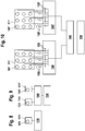
- FIG. 8 to 10 For example, individual elements as used to implement a receiver according to embodiments of the present invention are shown as a block diagram.
- Fig. 8 1 shows a pixel 111 with a single SPAD 101.
- the pixel is connected to a distance determiner 130.
- Fig. 9 shows two pixels 111, 111 ', each with a SPAD 101, 101'.
- the pixels 111, 111 ' are connected to a multiplexer 140, which selectively passes the detection signals supplied by the pixels 111, 111' to a distance determining device 130.
- Fig. 10 an arrangement of two pixels 111, 111 'is shown, each with nine SPADs 101, 101'.
- the detection signals from the individual SPADs 101, 101 ' are forwarded to a combiner 160, 160', if appropriate after a time delay caused by additional delay elements 150, 150 '.
- the delay can be used to compensate for differences in transit time and thus the temporal synchronization of the SPADs of a pixel or different pixels.
- the detection signals are combined.
- the signals generated by the SPADs can be shortened in time by means of pulse shorteners 155, 155 '.
- the combined detection signals are passed from the combiners 160, 160 'to a multiplexer 140 and from there to a distance determining device 130.
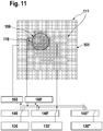
- N 92 pixels 111.
- 48 pixels have only a single SPAD
- 24 pixels each have four SPADs in a 2x2 array
- 20 pixels each have 9 SPADs in a 3x3 arrangement.
- Each pixel 111 with more than one SPAD 101 is exactly connected to a combiner 160, 160 '.
- the outputs of the pixels 111 with only one SPAD and the combiner 160 are connected to inputs of K multiplexers 140, respectively.
- FIG. 11 A hatched area indicates an effective detector area 170 comprising those pixels 111 that are actually illuminated by the laser light of the laser spot 109 and from which a distance measurement to the target object can be performed.
- An embodiment of the invention is based on the core idea of advantageously designing the type of arrangement of individual SPADs in pixels whose signals are combined before they are fed to a time evaluation unit (that is to say a distance determination device / a binning scheme) for further evaluation.
- the amount of SPADs whose signals are combined by means of a combiner forms a pixel.
- the individual pixels can be operated independently of each other.
- a phase evaluation of a continuous wave or alternatively a time-of-flight evaluation of a pulse for each individual pixel can be carried out.
- a combination of several SPADs into pixels can be configured spatially in such a way that the signal-to-noise ratio at both large and small distances, in particular under strong background lighting with a few distance determination devices can be optimized. This can be achieved via a location-dependent adaptation of the size of the pixels or the number of SPADs that are combined to form a pixel.
- the type of arrangement of optional pixels with only one SPAD or pixels with different size and number of SPADs, optimized especially for increasing the signal-to-noise ratio in a laser rangefinder, represents one of the distinguishing features of both conventional laser rangefinders and 3D cameras.
- This arrangement can reduce the requirements for an adjustment of an optical system within the measuring device and can at the same time contribute to an optimized signal-to-noise ratio, even if the receiving device is not located in the image plane of the optical system, as occurs, for example, in fixed-focus systems can.
- a detection surface can be dimensioned so large that the requirements for the adjustment of the receiving optics can be reduced.
- the influence of optical aberrations, in particular the defocusing errors due to insufficient depth of field, can be minimized.
- the demands on the optical quality of the receiving optics can be reduced.
- Another advantage can be the optimization of the signal-to-noise ratio, especially for large measurement distances under high background light content. This can be achieved by optimally adapting, ie minimizing, the effective detection area at all distances to the size of the actually imaged laser measurement spot in the detection plane. Once the measurement has been completed, the signals of only those individual SPADs or pixels with several SPADs that actually receive laser radiation can be evaluated. As a result, the effective detection area can be reduced and the noise contribution of the background light can be minimized, which can be synonymous with an improvement in the signal-to-noise ratio.
- Another advantage may be that fewer ranging devices are needed than SPADs due to the merging of multiple SPADs within a pixel. This can reduce a required chip area of an integrated circuit. Especially with laser rangefinders, which typically operate with a fixed focal length, this advantage can play an important role, since the laser spot diameter can then vary depending on the distance of the target object. Fig. 6 illustrates this for a system in which the parallax error is not corrected. In order to optimize the signal-to-noise ratio as described above by minimizing the effective detection area, with larger laser spot diameters, that is usually at smaller distances of the target object, accordingly only a lower resolution of the detector may be required. This circumstance can be exploited by the location-dependent combination of SPADs to pixels.
- the effective detection area that is to say the area which is taken into account in the evaluation of the measurement
- the number of distance determination devices required can be reduced even further by additionally using multiplexing in addition to the combination of SPADs becomes.
- the pixels receiving laser radiation can first be identified and then distributed to the distance determination devices for the actual measurement. If N is the total number of pixels with one or more SPADs and M is the number of distance estimators available for evaluation, then N / M preliminary measurements must be performed for identification at maximum. The measuring task can therefore be carried out with a few measurements, ideally with a single measurement.
- Another advantage may be that individual pixels can be calibrated independently of each other, for example, in terms of phase offset.
Landscapes
- Engineering & Computer Science (AREA)
- Physics & Mathematics (AREA)
- General Physics & Mathematics (AREA)
- Radar, Positioning & Navigation (AREA)
- Remote Sensing (AREA)
- Computer Networks & Wireless Communication (AREA)
- Electromagnetism (AREA)
- Optical Radar Systems And Details Thereof (AREA)
- Measurement Of Optical Distance (AREA)
Claims (16)
- Dispositif de mesure (10) destiné à mesurer optiquement une distance, en particulier un dispositif de mesure tenu à la main, comprenant :un dispositif d'émission (12) destiné à émettre un rayonnement de mesure optique (13) vers un objet cible (15) ;un dispositif de réception (14) comportant une surface de détection (110) destinée à détecter un rayonnement de mesure optique (16) renvoyé par l'objet cible (15) ; etun dispositif d'analyse (36) ;dans lequel la surface de détection (110) comprend une pluralité de pixels (111),dans lequel chaque pixel (111) comprend au moins une SPAD (101) et dans lequel chacun de la pluralité de pixels (111) est connecté au dispositif d'analyse (36) ;dans lequel le dispositif d'émission (12) et le dispositif de réception (14) sont conçus de manière à ce que le rayonnement de mesure optique (16) renvoyé par l'objet cible (15) éclaire simultanément une pluralité de pixels (111) ;dans lequel le dispositif d'analyse (36) est conçu pour obtenir une distance (48) entre le dispositif de mesure (10) et l'objet cible (15) sur la base d'une analyse de signaux de détection de multiples pixels (111), caractérisé en ce qu'au moins certains pixels (111) contiennent respectivement une pluralité de SPAD (101).
- Dispositif de mesure selon la revendication 1, dans lequel le dispositif d'analyse (36) comprend au moins un dispositif de détermination de distance (130), qui est conçu pour obtenir un temps de propagation du rayonnement de mesure (13, 16) entre une émission effectuée par le dispositif d'émission (12) et une détection d'un rayonnement de mesure (16) renvoyé par l'objet cible (15) et déterminer à partir de celui-ci une distance.
- Dispositif de mesure selon la revendication 2, dans lequel une pluralité de pixels (111) sont connectés à un dispositif de détermination de distance (130) et le dispositif de détermination de distance (130) est conçu pour déterminer la distance sur la base de signaux de détection de la pluralité de pixels (111).
- Dispositif de mesure selon la revendication 2, dans lequel le dispositif d'analyse (36) comprend une pluralité de dispositifs de détermination de distance (130) et en ce que le dispositif d'analyse (36) est conçu pour déterminer la distance (48) entre le dispositif de mesure (10) et l'objet cible (15) sur la base des distances déterminées par les dispositifs de détermination de distance (130).
- Dispositif de mesure selon l'une quelconque des revendications précédentes, comprenant en outre au moins un combineur (160) qui est conçu pour combiner des signaux de détection de diodes SPAD (101) contenues dans un pixel individuel (111).
- Dispositif de mesure selon l'une quelconque des revendications précédentes, comprenant en outre au moins un dispositif de raccourcissement d'impulsion destiné à raccourcir temporellement un signal numérique généré par une diode SPAD.
- Dispositif de mesure selon l'une quelconque des revendications précédentes, dans lequel le nombre de diodes SPAD (101) contenues dans un pixel (111) varie en fonction de la position du pixel (111) à l'intérieur de la surface de détection (110) du dispositif de réception (14).
- Dispositif de mesure selon l'une quelconque des revendications précédentes, dans lequel une surface de diodes SPAD contenues dans un pixel (111) varie en fonction de la position du pixel (111) à l'intérieur de la surface de détection (110) du dispositif de réception (14).
- Dispositif de mesure selon la revendication 7 ou 8, dans lequel le dispositif d'émission (12) et le dispositif de réception (14) sont disposés côte à côte le long d'un axe de parallaxe (113) et dans lequel le nombre de diodes SPAD (101) contenues dans un pixel (111) varie en fonction de la position le long de l'axe de parallaxe (113).
- Dispositif de mesure selon la revendication 7, 8 ou 9, dans lequel le nombre de diodes SPAD (101) qui sont contenues dans un pixel (111) est inférieur dans des pixels (111) proches du dispositif d'émission (12) à ce qu'il est dans des pixels (111) éloignés du dispositif d'émission (12).
- Dispositif de mesure selon l'une quelconque des revendications 7 à 10, dans lequel le nombre de diodes SPAD (101) contenues dans un pixel (111) est inférieur dans les pixels (111) proche du centre (122) de la surface de détection (110) à ce qu'il est dans des pixels (111) éloignés du centre (122) de la surface de détection (110).
- Dispositif de mesure selon l'une quelconque des revendications précédentes, dans lequel le dispositif d'émission (12) et le dispositif de réception (14) sont conçus de manière à ce qu'un nombre de pixels (111) qui sont simultanément éclairés par le rayonnement de mesure optique (16) renvoyé par l'objet cible (15) varie en fonction d'une distance (48) entre l'objet cible (15) et le dispositif de mesure (10).
- Dispositif de mesure selon l'une quelconque des revendications précédentes, comprenant en outre une optique de focalisation non automatique (52) destinée à acheminer le rayonnement de mesure optique (16) renvoyé par l'objet cible vers la surface de détection (110).
- Dispositif de mesure selon l'une quelconque des revendications précédentes, dans lequel le dispositif de réception (14) et le dispositif d'analyse (36) sont conçus de manière à ce que les signaux de détection de pixels individuels (111) puissent être analysés par le dispositif d'analyse (36) indépendamment de signaux de détection d'autres pixels (111).
- Dispositif de mesure selon l'une quelconque des revendications précédentes, dans lequel le dispositif de réception (14) et le dispositif d'analyse (36) sont conçus pour déterminer une distance (48) entre le dispositif de mesure (10) et l'objet cible (15) sur la base d'une analyse de signaux de détection provenant exclusivement des pixels (111) situés à l'intérieur d'une surface de détection effective (170) sur laquelle est renvoyée la lumière de la surface de l'objet cible qui est éclairée par le dispositif d'émission.
- Dispositif de mesure selon l'une quelconque des revendications précédentes, comprenant en outre au moins un multiplexeur (140) conçu pour réacheminer sélectivement des signaux de détection de multiples pixels (111) vers le dispositif d'analyse (36).
Applications Claiming Priority (2)
| Application Number | Priority Date | Filing Date | Title |
|---|---|---|---|
| DE102009029372A DE102009029372A1 (de) | 2009-09-11 | 2009-09-11 | Messvorrichtung zur Messung einer Entfernung zwischen der Messvorrichtung und einem Zielobjekt mit Hilfe optischer Messstrahlung |
| EP10734971.4A EP2475958B1 (fr) | 2009-09-11 | 2010-07-15 | Dispositif de télémétrie optique |
Related Parent Applications (2)
| Application Number | Title | Priority Date | Filing Date |
|---|---|---|---|
| EP10734971.4A Division EP2475958B1 (fr) | 2009-09-11 | 2010-07-15 | Dispositif de télémétrie optique |
| EP10734971.4A Division-Into EP2475958B1 (fr) | 2009-09-11 | 2010-07-15 | Dispositif de télémétrie optique |
Publications (2)
| Publication Number | Publication Date |
|---|---|
| EP3130889A1 EP3130889A1 (fr) | 2017-02-15 |
| EP3130889B1 true EP3130889B1 (fr) | 2018-06-13 |
Family
ID=42711912
Family Applications (3)
| Application Number | Title | Priority Date | Filing Date |
|---|---|---|---|
| EP16187159.5A Active EP3130890B1 (fr) | 2009-09-11 | 2010-07-15 | Télémètre optique |
| EP16187158.7A Active EP3130889B1 (fr) | 2009-09-11 | 2010-07-15 | Télémètre optique |
| EP10734971.4A Active EP2475958B1 (fr) | 2009-09-11 | 2010-07-15 | Dispositif de télémétrie optique |
Family Applications Before (1)
| Application Number | Title | Priority Date | Filing Date |
|---|---|---|---|
| EP16187159.5A Active EP3130890B1 (fr) | 2009-09-11 | 2010-07-15 | Télémètre optique |
Family Applications After (1)
| Application Number | Title | Priority Date | Filing Date |
|---|---|---|---|
| EP10734971.4A Active EP2475958B1 (fr) | 2009-09-11 | 2010-07-15 | Dispositif de télémétrie optique |
Country Status (7)
| Country | Link |
|---|---|
| US (1) | US8908157B2 (fr) |
| EP (3) | EP3130890B1 (fr) |
| CN (2) | CN105066953B (fr) |
| DE (1) | DE102009029372A1 (fr) |
| ES (1) | ES2614108T3 (fr) |
| IN (1) | IN2012DN00222A (fr) |
| WO (1) | WO2011029645A1 (fr) |
Families Citing this family (117)
| Publication number | Priority date | Publication date | Assignee | Title |
|---|---|---|---|---|
| US12025807B2 (en) | 2010-10-04 | 2024-07-02 | Gerard Dirk Smits | System and method for 3-D projection and enhancements for interactivity |
| DE102011005746A1 (de) * | 2011-03-18 | 2012-09-20 | Robert Bosch Gmbh | Messvorrichtung zur mehrdimensionalen Vermessung eines Zielobjekts |
| GB2492848A (en) * | 2011-07-15 | 2013-01-16 | Softkinetic Sensors Nv | Optical distance measurement |
| FR2984522B1 (fr) * | 2011-12-20 | 2014-02-14 | St Microelectronics Grenoble 2 | Dispositif de detection de la proximite d'un objet, comprenant des photodiodes spad |
| FR2985570A1 (fr) | 2012-01-09 | 2013-07-12 | St Microelectronics Grenoble 2 | Dispositif de detection de la proximite d'un objet, comprenant des photodiodes spad |
| EP2680034B1 (fr) * | 2012-06-26 | 2014-09-10 | Sick Ag | Optoelectronic sensor and method for detecting the distance of objects |
| EP2708913A1 (fr) * | 2012-09-18 | 2014-03-19 | Sick Ag | Capteur optoélectronique et procédé de détection d'objet |
| JP6236758B2 (ja) * | 2012-10-09 | 2017-11-29 | 株式会社豊田中央研究所 | 光学的測距装置 |
| DE102012223689B3 (de) * | 2012-12-19 | 2014-01-02 | Robert Bosch Gmbh | Messvorrichtung und Verfahren zur Referenzierung für einen digitalen Laserentfernungsmesser, sowie Laserentfernungsmesser |
| WO2014097181A1 (fr) * | 2012-12-19 | 2014-06-26 | Basf Se | Détecteur pour détecter de manière optique au moins un objet |
| DE202014010668U1 (de) | 2013-03-13 | 2016-06-17 | Robert Bosch Gmbh | Entfernungsmessgerät, insbesondere elektro-optischer Entfernungsmesser |
| FR3005878B1 (fr) * | 2013-05-24 | 2016-05-27 | Saint Gobain | Procede d'obtention d'un substrat muni d'un revetement |
| EP3008757B1 (fr) | 2013-06-13 | 2024-05-15 | Basf Se | Détecteur optique et son procédé de fabrication |
| US9829564B2 (en) | 2013-06-13 | 2017-11-28 | Basf Se | Detector for optically detecting at least one longitudinal coordinate of one object by determining a number of illuminated pixels |
| EP3008421A1 (fr) | 2013-06-13 | 2016-04-20 | Basf Se | Détecteur permettant de détecter optiquement l'orientation d'au moins un objet |
| DE102013213285A1 (de) * | 2013-07-08 | 2015-01-08 | Robert Bosch Gmbh | Bestimmung eines Abstands und eines Winkels in Bezug auf eine Ebene mittels mehrerer Entfernungsmessungen |
| CN105637382B (zh) | 2013-08-19 | 2017-08-25 | 巴斯夫欧洲公司 | 用于确定至少一种物体的位置的检测器 |
| EP3036503B1 (fr) | 2013-08-19 | 2019-08-07 | Basf Se | Détecteur optique |
| US10203399B2 (en) | 2013-11-12 | 2019-02-12 | Big Sky Financial Corporation | Methods and apparatus for array based LiDAR systems with reduced interference |
| US9360554B2 (en) | 2014-04-11 | 2016-06-07 | Facet Technology Corp. | Methods and apparatus for object detection and identification in a multiple detector lidar array |
| DE102014207599B4 (de) * | 2014-04-23 | 2024-09-26 | Robert Bosch Gmbh | Verfahren und Computerprogramm zum Betreiben eines Fotodetektors |
| JP6321145B2 (ja) * | 2014-05-02 | 2018-05-09 | 富士フイルム株式会社 | 測距装置、測距方法、及び測距プログラム |
| DE102014209375A1 (de) | 2014-05-16 | 2015-11-19 | Robert Bosch Gmbh | Mehrzielfähiger Laserentfernungsmesser |
| JP2017521770A (ja) * | 2014-06-16 | 2017-08-03 | ビーエーエスエフ ソシエタス・ヨーロピアBasf Se | 少なくとも1個のオブジェクトの位置を決定するための検出器 |
| EP3167304A4 (fr) | 2014-07-08 | 2018-02-21 | Basf Se | Détecteur pour déterminer une position d'au moins un objet |
| EP2998700B2 (fr) | 2014-09-18 | 2022-12-21 | Hexagon Technology Center GmbH | Dispositif de mesure de distance électro-optique et procédé de mesure de distance |
| JP6578006B2 (ja) | 2014-09-29 | 2019-09-18 | ビーエーエスエフ ソシエタス・ヨーロピアBasf Se | 少なくとも1個の物体の位置を光学的に求めるための検出器 |
| DE102014117097B3 (de) * | 2014-11-21 | 2016-01-21 | Odos Imaging Ltd. | Abstandsmessvorrichtung und Verfahren zum Bestimmen eines Abstands |
| US11125880B2 (en) | 2014-12-09 | 2021-09-21 | Basf Se | Optical detector |
| US9812486B2 (en) * | 2014-12-22 | 2017-11-07 | Google Inc. | Time-of-flight image sensor and light source driver having simulated distance capability |
| JP6841769B2 (ja) | 2015-01-30 | 2021-03-10 | トリナミクス ゲゼルシャフト ミット ベシュレンクテル ハフツング | 少なくとも1個の物体を光学的に検出する検出器 |
| US10036801B2 (en) | 2015-03-05 | 2018-07-31 | Big Sky Financial Corporation | Methods and apparatus for increased precision and improved range in a multiple detector LiDAR array |
| CN107710015B (zh) * | 2015-07-03 | 2021-08-24 | 新唐科技日本株式会社 | 距离测量装置以及距离图像合成方法 |
| EP3325917B1 (fr) | 2015-07-17 | 2020-02-26 | trinamiX GmbH | Détecteur pour détecter optiquement au moins un objet |
| US10620300B2 (en) | 2015-08-20 | 2020-04-14 | Apple Inc. | SPAD array with gated histogram construction |
| KR102539263B1 (ko) | 2015-09-14 | 2023-06-05 | 트리나미엑스 게엠베하 | 적어도 하나의 물체의 적어도 하나의 이미지를 기록하는 카메라 |
| FR3043797A1 (fr) * | 2015-11-16 | 2017-05-19 | Stmicroelectronics (Grenoble 2) Sas | |
| FR3043796A1 (fr) | 2015-11-16 | 2017-05-19 | Stmicroelectronics (Grenoble 2) Sas | |
| US20170168162A1 (en) * | 2015-12-09 | 2017-06-15 | The Boeing Company | Light detection and ranging (lidar) imaging systems and methods |
| JP6854828B2 (ja) | 2015-12-18 | 2021-04-07 | ジェラルド ディルク スミッツ | 物体のリアルタイム位置検知 |
| EP3182158B1 (fr) * | 2015-12-18 | 2021-11-24 | STMicroelectronics (Research & Development) Limited | Appareil de télémétrie |
| EP3182156B1 (fr) | 2015-12-18 | 2021-01-27 | STMicroelectronics (Research & Development) Limited | Appareil de télémétrie |
| EP3391085B1 (fr) * | 2015-12-18 | 2023-04-19 | Gerard Dirk Smits | Détection de position en temps réel d'objets |
| FR3048316B1 (fr) * | 2016-02-29 | 2019-06-28 | Sagem Defense Securite | Dispositif de detection d'un spot laser |
| EP3423865B1 (fr) * | 2016-03-01 | 2024-03-06 | Brightway Vision Ltd. | Appareil, système et procédé d'imagerie à déclenchement |
| US9866816B2 (en) | 2016-03-03 | 2018-01-09 | 4D Intellectual Properties, Llc | Methods and apparatus for an active pulsed 4D camera for image acquisition and analysis |
| EP3258228B1 (fr) * | 2016-06-17 | 2018-05-09 | Sick Ag | Récepteur de lumière ayant des photodiodes à avalanche en mode geiger et procédé de lecture |
| DE102016112557B4 (de) | 2016-07-08 | 2019-08-22 | Jenoptik Advanced Systems Gmbh | Optische Stahlformungseinheit und Entfernungsmessvorrichtung |
| DE102016113131A1 (de) | 2016-07-15 | 2018-01-18 | Sick Ag | Optoelektronischer Sensor und Verfahren zur Erfassung eines Objekts in einem Überwachungsbereich |
| CN109564927B (zh) | 2016-07-29 | 2023-06-20 | 特里纳米克斯股份有限公司 | 光学传感器和用于光学检测的检测器 |
| JP6812554B2 (ja) * | 2016-08-24 | 2021-01-13 | アウスター インコーポレイテッド | フィールド内の距離情報を収集するための光学システム |
| CN106226755B (zh) * | 2016-08-30 | 2019-05-21 | 北京小米移动软件有限公司 | 机器人 |
| CN109791195B (zh) * | 2016-09-22 | 2023-02-03 | 苹果公司 | 用于光达的自适应发射功率控制 |
| EP3301476B1 (fr) * | 2016-09-28 | 2023-03-15 | STMicroelectronics (Research & Development) Limited | Appareil comprenant une camera et un module de détection de distance basé sur une diode à avalanche à photon unique à temps de vol pour contrôler la caméra et procédé correspondant |
| WO2018077868A1 (fr) | 2016-10-25 | 2018-05-03 | Trinamix Gmbh | Détecteur pour détection optique d'au moins un objet |
| EP3532796A1 (fr) | 2016-10-25 | 2019-09-04 | trinamiX GmbH | Détecteur optique infrarouge à filtre intégré |
| DE102016221049A1 (de) * | 2016-10-26 | 2018-04-26 | Robert Bosch Gmbh | Vorrichtung und Verfahren zum Empfangen eines reflektierten Lichtpulses in einem Lidar-System |
| US11860292B2 (en) | 2016-11-17 | 2024-01-02 | Trinamix Gmbh | Detector and methods for authenticating at least one object |
| EP3571522B1 (fr) | 2016-11-17 | 2023-05-10 | trinamiX GmbH | Détecteur pour détection optique d'au moins un objet |
| DE102016122645A1 (de) * | 2016-11-24 | 2018-05-24 | Valeo Schalter Und Sensoren Gmbh | Empfangseinrichtung für eine optische Detektionsvorrichtung, Detektionsvorrichtung und Fahrerassistenzsystem |
| EP3563347A4 (fr) | 2016-12-27 | 2020-06-24 | Gerard Dirk Smits | Systèmes et procédés pour la perception par les machines |
| DE102017202353B4 (de) * | 2017-02-14 | 2020-07-23 | Fraunhofer-Gesellschaft zur Förderung der angewandten Forschung e.V. | Vorrichtung zur ermittlung eines abstands zu einem objekt und entsprechendes verfahren |
| JP6867212B2 (ja) * | 2017-03-31 | 2021-04-28 | 株式会社デンソー | 光検出器及び測距装置 |
| JP7204667B2 (ja) | 2017-04-20 | 2023-01-16 | トリナミクス ゲゼルシャフト ミット ベシュレンクテル ハフツング | 光検出器 |
| DE102017209643A1 (de) * | 2017-06-08 | 2018-12-13 | Robert Bosch Gmbh | Betriebsverfahren und Steuereinheit für ein LiDAR-System, LiDAR-System und Arbeitsvorrichtung |
| DE102017113674B4 (de) * | 2017-06-21 | 2019-03-28 | Sick Ag | Optoelektronischer Sensor und Verfahren zur Messung der Entfernung zu einem Objekt |
| CN107272010B (zh) * | 2017-06-21 | 2020-07-14 | 锐芯微电子股份有限公司 | 距离传感器及其距离测量方法、3d图像传感器 |
| CN110998223B (zh) | 2017-06-26 | 2021-10-29 | 特里纳米克斯股份有限公司 | 用于确定至少一个对像的位置的检测器 |
| EP3646057A1 (fr) * | 2017-06-29 | 2020-05-06 | Apple Inc. | Cartographie de profondeur de temps de vol à compensation de parallaxe |
| EP3428574A1 (fr) * | 2017-07-11 | 2019-01-16 | Fondazione Bruno Kessler | Dispositif de mesure de distance et procédé de mesure de ladite distance |
| EP3438699A1 (fr) * | 2017-07-31 | 2019-02-06 | Hexagon Technology Center GmbH | Télémètre comprenant un système spad destiné à prendre en compte des cibles multiples |
| EP3450915B1 (fr) * | 2017-08-30 | 2020-11-25 | Hexagon Technology Center GmbH | Tachéomètre électronique ou théodolite pourvus de fonction de balayage et de zones de réception réglables du récepteur |
| DE102017215783A1 (de) * | 2017-09-07 | 2019-03-07 | Robert Bosch Gmbh | Verfahren zum Betrieb eines Laserentfernungsmessgeräts |
| DE102017215766A1 (de) * | 2017-09-07 | 2019-03-07 | Robert Bosch Gmbh | Verfahren zum Betrieb eines Laserentfernungsmessgeräts |
| US10955552B2 (en) | 2017-09-27 | 2021-03-23 | Apple Inc. | Waveform design for a LiDAR system with closely-spaced pulses |
| DE102017222972A1 (de) * | 2017-12-15 | 2019-07-04 | Ibeo Automotive Systems GmbH | Empfangsanordnung zum Empfang von Lichtsignalen |
| DE102017222969A1 (de) * | 2017-12-15 | 2019-06-19 | Ibeo Automotive Systems GmbH | Verfahren zur verbesserten Nah- und Ferndetektion einer LIDAR Empfangseinheit |
| DE102017222970A1 (de) * | 2017-12-15 | 2019-06-19 | Ibeo Automotive Systems GmbH | LIDAR Messsystem |
| DE102017222971A1 (de) * | 2017-12-15 | 2019-07-11 | Ibeo Automotive Systems GmbH | LIDAR Empfangseinheit |
| DE102017222974A1 (de) | 2017-12-15 | 2019-06-19 | Ibeo Automotive Systems GmbH | Anordnung und Verfahren zur Ermittlung einer Entfernung wenigstens eines Objekts mit Lichtsignalen |
| KR102403544B1 (ko) | 2017-12-18 | 2022-05-30 | 애플 인크. | 방출기들의 어드레스가능 어레이를 사용하는 비행 시간 감지 |
| DE102017223102A1 (de) * | 2017-12-18 | 2019-06-19 | Robert Bosch Gmbh | Multipuls-Lidarsystem zur mehrdimensionalen Erfassung von Objekten |
| JP7013925B2 (ja) * | 2018-02-23 | 2022-02-01 | 株式会社デンソー | 光学的測距装置およびその方法 |
| CN112154348B (zh) * | 2018-04-09 | 2024-08-23 | 奥卢大学 | 距离成像装置和方法 |
| DE102018205378A1 (de) * | 2018-04-10 | 2019-10-10 | Ibeo Automotive Systems GmbH | Verfahren zur Ansteuerung von Sensorelementen eines LIDAR Messsystems |
| JP7246863B2 (ja) | 2018-04-20 | 2023-03-28 | ソニーセミコンダクタソリューションズ株式会社 | 受光装置、車両制御システム及び測距装置 |
| JP7131099B2 (ja) * | 2018-06-06 | 2022-09-06 | 株式会社デンソー | 光学的測距装置およびその方法 |
| DE102018210291B4 (de) * | 2018-06-25 | 2020-11-05 | Robert Bosch Gmbh | Kompensationseinrichtung für ein biaxiales Lidarsystem |
| CN109143252B (zh) * | 2018-08-08 | 2022-08-30 | 合肥泰禾智能科技集团股份有限公司 | Tof深度相机距离校准的方法及装置 |
| EP3608688B1 (fr) | 2018-08-09 | 2021-01-27 | OMRON Corporation | Dispositif de mesure de distance |
| EP3614174B1 (fr) * | 2018-08-21 | 2021-06-23 | Omron Corporation | Dispositif et procédé de mesure de la distance |
| KR102604902B1 (ko) | 2019-02-11 | 2023-11-21 | 애플 인크. | 펄스형 빔들의 희소 어레이를 사용하는 깊이 감지 |
| DE102019207741A1 (de) * | 2019-05-27 | 2020-12-03 | Infineon Technologies Ag | Ein LIDAR-System, ein Verfahren für ein LIDAR-System und ein Empfänger für ein LIDAR-System mit ersten und zweiten Umwandlungselementen |
| US11500094B2 (en) | 2019-06-10 | 2022-11-15 | Apple Inc. | Selection of pulse repetition intervals for sensing time of flight |
| DE102019209697A1 (de) * | 2019-07-02 | 2021-01-07 | Ibeo Automotive Systems GmbH | Lidar-Empfangseinheit |
| US11555900B1 (en) | 2019-07-17 | 2023-01-17 | Apple Inc. | LiDAR system with enhanced area coverage |
| DE102019212615A1 (de) * | 2019-08-22 | 2021-02-25 | Robert Bosch Gmbh | Detektor mit Parallax-Kompensation |
| DE102019124142A1 (de) * | 2019-09-09 | 2021-03-11 | pmdtechnologies ag | Lichtlaufzeitkamerasystem |
| TWI711834B (zh) * | 2019-11-28 | 2020-12-01 | 國立交通大學 | 測距裝置及方法 |
| US11733359B2 (en) | 2019-12-03 | 2023-08-22 | Apple Inc. | Configurable array of single-photon detectors |
| US11373322B2 (en) | 2019-12-26 | 2022-06-28 | Stmicroelectronics, Inc. | Depth sensing with a ranging sensor and an image sensor |
| WO2021174227A1 (fr) | 2020-02-27 | 2021-09-02 | Gerard Dirk Smits | Balayage à haute résolution d'objets distants avec des faisceaux laser panoramiques rapides et récupération de signal par réseau de pixels agité |
| JP7434002B2 (ja) | 2020-03-17 | 2024-02-20 | 株式会社東芝 | 光検出器及び距離計測装置 |
| JP7383542B2 (ja) * | 2020-03-24 | 2023-11-20 | 株式会社東芝 | 光検出器及び距離計測装置 |
| CN111830530B (zh) * | 2020-06-04 | 2023-02-24 | 深圳奥锐达科技有限公司 | 一种距离测量方法、系统及计算机可读存储介质 |
| CN111965658B (zh) * | 2020-07-17 | 2023-12-12 | 深圳奥锐达科技有限公司 | 一种距离测量系统、方法及计算机可读存储介质 |
| CN114167431A (zh) * | 2020-08-21 | 2022-03-11 | 上海禾赛科技有限公司 | 利用激光雷达探测的方法以及激光雷达 |
| WO2022041647A1 (fr) * | 2020-08-25 | 2022-03-03 | 神盾股份有限公司 | Réseau de détection de lumière et appareil de télémétrie à temps de vol |
| JP7423485B2 (ja) * | 2020-09-18 | 2024-01-29 | 株式会社東芝 | 距離計測装置 |
| US12007509B2 (en) | 2020-09-24 | 2024-06-11 | Lg Innotek Co., Ltd. | Systems and methods for pre-blinding LIDAR detectors |
| CN112213711B (zh) * | 2020-09-28 | 2024-07-05 | 上海数迹智能科技有限公司 | 一种tof相机的校准方法 |
| CN112198519B (zh) * | 2020-10-01 | 2024-05-03 | 奥比中光科技集团股份有限公司 | 一种距离测量系统及方法 |
| CN112596068A (zh) * | 2020-10-28 | 2021-04-02 | 深圳奥锐达科技有限公司 | 一种采集器、距离测量系统及电子设备 |
| US11509848B2 (en) * | 2021-01-11 | 2022-11-22 | Microsoft Technology Licensing, Llc | Photodiode assembly |
| US11681028B2 (en) | 2021-07-18 | 2023-06-20 | Apple Inc. | Close-range measurement of time of flight using parallax shift |
| CN114355370A (zh) * | 2021-08-26 | 2022-04-15 | 国科光芯(海宁)科技股份有限公司 | 一种距离探测器、一种距离探测方法及装置 |
| US20230333216A1 (en) * | 2022-04-13 | 2023-10-19 | Allegro Microsystems, Llc | Photosensor having range parallax compensation |
Family Cites Families (10)
| Publication number | Priority date | Publication date | Assignee | Title |
|---|---|---|---|---|
| US5035060A (en) * | 1990-07-05 | 1991-07-30 | The United States Of America As Represented By The Secretary Of The Interior | Method of mapping underground mines |
| AU7953201A (en) * | 2000-08-25 | 2002-03-04 | Kurt Giger | Method and device for measuring distances |
| DE10244553B3 (de) * | 2002-09-25 | 2004-02-05 | Robert Bosch Gmbh | Interferometrische Messeinrichtung |
| DE102004023998A1 (de) * | 2004-05-14 | 2005-12-08 | Robert Bosch Gmbh | Vorrichtung zur optischen Distanzmessung |
| CN1273842C (zh) | 2004-06-18 | 2006-09-06 | 中国科学院上海技术物理研究所 | 智能自适应激光扫描测距成像装置 |
| US7301608B1 (en) * | 2005-01-11 | 2007-11-27 | Itt Manufacturing Enterprises, Inc. | Photon-counting, non-imaging, direct-detect LADAR |
| US8355117B2 (en) * | 2005-12-21 | 2013-01-15 | Ecole Polytechnique Federale De Lausanne | Method and arrangement for measuring the distance to an object |
| DE102006013290A1 (de) * | 2006-03-23 | 2007-09-27 | Robert Bosch Gmbh | Vorrichtung zur optischen Distanzmessung sowie Verfahren zum Betrieb einer solchen Vorrichtung |
| CN100394211C (zh) * | 2006-04-07 | 2008-06-11 | 哈尔滨工业大学 | 多频同步调制激光测距方法与装置 |
| EP1860462A1 (fr) | 2006-05-23 | 2007-11-28 | Leica Geosystems AG | Procédé de mesure de distances et appareil de mesure de distances destinés à l'enregistrement des dimensions spatiales d'une cible |
-
2009
- 2009-09-11 DE DE102009029372A patent/DE102009029372A1/de not_active Ceased
-
2010
- 2010-07-15 US US13/395,183 patent/US8908157B2/en active Active
- 2010-07-15 EP EP16187159.5A patent/EP3130890B1/fr active Active
- 2010-07-15 EP EP16187158.7A patent/EP3130889B1/fr active Active
- 2010-07-15 ES ES10734971.4T patent/ES2614108T3/es active Active
- 2010-07-15 CN CN201510425108.XA patent/CN105066953B/zh active Active
- 2010-07-15 WO PCT/EP2010/060212 patent/WO2011029645A1/fr active Application Filing
- 2010-07-15 EP EP10734971.4A patent/EP2475958B1/fr active Active
- 2010-07-15 IN IN222DEN2012 patent/IN2012DN00222A/en unknown
- 2010-07-15 CN CN201080040251.2A patent/CN102549381B/zh active Active
Non-Patent Citations (1)
| Title |
|---|
| None * |
Also Published As
| Publication number | Publication date |
|---|---|
| EP3130890B1 (fr) | 2018-06-20 |
| IN2012DN00222A (fr) | 2015-05-01 |
| US20120249998A1 (en) | 2012-10-04 |
| ES2614108T3 (es) | 2017-05-29 |
| CN102549381A (zh) | 2012-07-04 |
| EP2475958B1 (fr) | 2016-11-02 |
| CN102549381B (zh) | 2015-08-19 |
| US8908157B2 (en) | 2014-12-09 |
| WO2011029645A1 (fr) | 2011-03-17 |
| CN105066953A (zh) | 2015-11-18 |
| CN105066953B (zh) | 2018-09-14 |
| DE102009029372A1 (de) | 2011-03-24 |
| EP2475958A1 (fr) | 2012-07-18 |
| EP3130889A1 (fr) | 2017-02-15 |
| EP3130890A1 (fr) | 2017-02-15 |
Similar Documents
| Publication | Publication Date | Title |
|---|---|---|
| EP3130889B1 (fr) | Télémètre optique | |
| EP2686700B1 (fr) | Dispositif de mesure de la distance séparant le dispositif de mesure et un objet cible à l'aide d'un rayonnement de mesure optique | |
| EP2686703B1 (fr) | Dispositif de mesure et appareil de mesure pour la mesure multidimensionnelle d'un objet cible | |
| EP2475957B2 (fr) | Télémètre optique | |
| DE102017101501B3 (de) | Optoelektronischer Sensor und Verfahren zur Bestimmung der Entfernung eines Objekts in einem Überwachungsbereich | |
| EP3279685B2 (fr) | Capteur optoélectronique et procédé de détection d'un objet | |
| EP2002208B1 (fr) | Dispositif de mesure optique de distances et son procédé de fonctionnement | |
| DE102006013292A1 (de) | Vorrichtung zur optischen Distanzmessung | |
| DE102018109544A1 (de) | Optoelektronischer Sensor und Verfahren zur Abstandsbestimmung | |
| DE212017000247U1 (de) | LiDAR-Vorrichtung | |
| DE102009045323A1 (de) | Optisches Entfernungsmessgerät mit Kalibrierungseinrichtung | |
| DE202013105389U1 (de) | Optoelektronischer Sensor mit im Geiger-Modus betriebenen Lawinenphotodiodenelementen | |
| DE102016113131A1 (de) | Optoelektronischer Sensor und Verfahren zur Erfassung eines Objekts in einem Überwachungsbereich | |
| DE102019100929A1 (de) | Langstreckendetektor für LIDAR | |
| EP3650888B1 (fr) | Détecteur optoélectronique et procédé de détection et de détermination de distance des objets | |
| DE202016104285U1 (de) | Optoelektronischer Sensor zur Erfassung eines Objekts | |
| DE102018132473B4 (de) | Optoelektronischer Sensor und Verfahren zur Erfassung eines Objekts | |
| EP3910373B1 (fr) | Lecture des éléments photodiodes d'avalanche en mode geiger | |
| EP4249949A1 (fr) | Détection et détermination de la distance d'un objet |
Legal Events
| Date | Code | Title | Description |
|---|---|---|---|
| PUAI | Public reference made under article 153(3) epc to a published international application that has entered the european phase |
Free format text: ORIGINAL CODE: 0009012 |
|
| AC | Divisional application: reference to earlier application |
Ref document number: 2475958 Country of ref document: EP Kind code of ref document: P |
|
| AK | Designated contracting states |
Kind code of ref document: A1 Designated state(s): AL AT BE BG CH CY CZ DE DK EE ES FI FR GB GR HR HU IE IS IT LI LT LU LV MC MK MT NL NO PL PT RO SE SI SK SM TR |
|
| 17P | Request for examination filed |
Effective date: 20170816 |
|
| RBV | Designated contracting states (corrected) |
Designated state(s): AL AT BE BG CH CY CZ DE DK EE ES FI FR GB GR HR HU IE IS IT LI LT LU LV MC MK MT NL NO PL PT RO SE SI SK SM TR |
|
| GRAP | Despatch of communication of intention to grant a patent |
Free format text: ORIGINAL CODE: EPIDOSNIGR1 |
|
| INTG | Intention to grant announced |
Effective date: 20180206 |
|
| GRAS | Grant fee paid |
Free format text: ORIGINAL CODE: EPIDOSNIGR3 |
|
| GRAA | (expected) grant |
Free format text: ORIGINAL CODE: 0009210 |
|
| AC | Divisional application: reference to earlier application |
Ref document number: 2475958 Country of ref document: EP Kind code of ref document: P |
|
| AK | Designated contracting states |
Kind code of ref document: B1 Designated state(s): AL AT BE BG CH CY CZ DE DK EE ES FI FR GB GR HR HU IE IS IT LI LT LU LV MC MK MT NL NO PL PT RO SE SI SK SM TR |
|
| REG | Reference to a national code |
Ref country code: GB Ref legal event code: FG4D Free format text: NOT ENGLISH |
|
| REG | Reference to a national code |
Ref country code: CH Ref legal event code: EP Ref country code: AT Ref legal event code: REF Ref document number: 1008957 Country of ref document: AT Kind code of ref document: T Effective date: 20180615 |
|
| REG | Reference to a national code |
Ref country code: IE Ref legal event code: FG4D Free format text: LANGUAGE OF EP DOCUMENT: GERMAN |
|
| REG | Reference to a national code |
Ref country code: DE Ref legal event code: R096 Ref document number: 502010015086 Country of ref document: DE |
|
| REG | Reference to a national code |
Ref country code: FR Ref legal event code: PLFP Year of fee payment: 9 |
|
| REG | Reference to a national code |
Ref country code: NL Ref legal event code: MP Effective date: 20180613 |
|
| REG | Reference to a national code |
Ref country code: LT Ref legal event code: MG4D |
|
| PG25 | Lapsed in a contracting state [announced via postgrant information from national office to epo] |
Ref country code: ES Free format text: LAPSE BECAUSE OF FAILURE TO SUBMIT A TRANSLATION OF THE DESCRIPTION OR TO PAY THE FEE WITHIN THE PRESCRIBED TIME-LIMIT Effective date: 20180613 Ref country code: SE Free format text: LAPSE BECAUSE OF FAILURE TO SUBMIT A TRANSLATION OF THE DESCRIPTION OR TO PAY THE FEE WITHIN THE PRESCRIBED TIME-LIMIT Effective date: 20180613 Ref country code: LT Free format text: LAPSE BECAUSE OF FAILURE TO SUBMIT A TRANSLATION OF THE DESCRIPTION OR TO PAY THE FEE WITHIN THE PRESCRIBED TIME-LIMIT Effective date: 20180613 Ref country code: BG Free format text: LAPSE BECAUSE OF FAILURE TO SUBMIT A TRANSLATION OF THE DESCRIPTION OR TO PAY THE FEE WITHIN THE PRESCRIBED TIME-LIMIT Effective date: 20180913 Ref country code: NO Free format text: LAPSE BECAUSE OF FAILURE TO SUBMIT A TRANSLATION OF THE DESCRIPTION OR TO PAY THE FEE WITHIN THE PRESCRIBED TIME-LIMIT Effective date: 20180913 Ref country code: FI Free format text: LAPSE BECAUSE OF FAILURE TO SUBMIT A TRANSLATION OF THE DESCRIPTION OR TO PAY THE FEE WITHIN THE PRESCRIBED TIME-LIMIT Effective date: 20180613 Ref country code: CY Free format text: LAPSE BECAUSE OF FAILURE TO SUBMIT A TRANSLATION OF THE DESCRIPTION OR TO PAY THE FEE WITHIN THE PRESCRIBED TIME-LIMIT Effective date: 20180613 |
|
| PG25 | Lapsed in a contracting state [announced via postgrant information from national office to epo] |
Ref country code: LV Free format text: LAPSE BECAUSE OF FAILURE TO SUBMIT A TRANSLATION OF THE DESCRIPTION OR TO PAY THE FEE WITHIN THE PRESCRIBED TIME-LIMIT Effective date: 20180613 Ref country code: GR Free format text: LAPSE BECAUSE OF FAILURE TO SUBMIT A TRANSLATION OF THE DESCRIPTION OR TO PAY THE FEE WITHIN THE PRESCRIBED TIME-LIMIT Effective date: 20180914 Ref country code: HR Free format text: LAPSE BECAUSE OF FAILURE TO SUBMIT A TRANSLATION OF THE DESCRIPTION OR TO PAY THE FEE WITHIN THE PRESCRIBED TIME-LIMIT Effective date: 20180613 |
|
| PG25 | Lapsed in a contracting state [announced via postgrant information from national office to epo] |
Ref country code: NL Free format text: LAPSE BECAUSE OF FAILURE TO SUBMIT A TRANSLATION OF THE DESCRIPTION OR TO PAY THE FEE WITHIN THE PRESCRIBED TIME-LIMIT Effective date: 20180613 |
|
| PG25 | Lapsed in a contracting state [announced via postgrant information from national office to epo] |
Ref country code: CZ Free format text: LAPSE BECAUSE OF FAILURE TO SUBMIT A TRANSLATION OF THE DESCRIPTION OR TO PAY THE FEE WITHIN THE PRESCRIBED TIME-LIMIT Effective date: 20180613 Ref country code: SK Free format text: LAPSE BECAUSE OF FAILURE TO SUBMIT A TRANSLATION OF THE DESCRIPTION OR TO PAY THE FEE WITHIN THE PRESCRIBED TIME-LIMIT Effective date: 20180613 Ref country code: EE Free format text: LAPSE BECAUSE OF FAILURE TO SUBMIT A TRANSLATION OF THE DESCRIPTION OR TO PAY THE FEE WITHIN THE PRESCRIBED TIME-LIMIT Effective date: 20180613 Ref country code: PL Free format text: LAPSE BECAUSE OF FAILURE TO SUBMIT A TRANSLATION OF THE DESCRIPTION OR TO PAY THE FEE WITHIN THE PRESCRIBED TIME-LIMIT Effective date: 20180613 Ref country code: IS Free format text: LAPSE BECAUSE OF FAILURE TO SUBMIT A TRANSLATION OF THE DESCRIPTION OR TO PAY THE FEE WITHIN THE PRESCRIBED TIME-LIMIT Effective date: 20181013 Ref country code: RO Free format text: LAPSE BECAUSE OF FAILURE TO SUBMIT A TRANSLATION OF THE DESCRIPTION OR TO PAY THE FEE WITHIN THE PRESCRIBED TIME-LIMIT Effective date: 20180613 |
|
| PG25 | Lapsed in a contracting state [announced via postgrant information from national office to epo] |
Ref country code: IT Free format text: LAPSE BECAUSE OF FAILURE TO SUBMIT A TRANSLATION OF THE DESCRIPTION OR TO PAY THE FEE WITHIN THE PRESCRIBED TIME-LIMIT Effective date: 20180613 Ref country code: SM Free format text: LAPSE BECAUSE OF FAILURE TO SUBMIT A TRANSLATION OF THE DESCRIPTION OR TO PAY THE FEE WITHIN THE PRESCRIBED TIME-LIMIT Effective date: 20180613 |
|
| REG | Reference to a national code |
Ref country code: CH Ref legal event code: PL |
|
| REG | Reference to a national code |
Ref country code: DE Ref legal event code: R097 Ref document number: 502010015086 Country of ref document: DE |
|
| PG25 | Lapsed in a contracting state [announced via postgrant information from national office to epo] |
Ref country code: LU Free format text: LAPSE BECAUSE OF NON-PAYMENT OF DUE FEES Effective date: 20180715 Ref country code: MC Free format text: LAPSE BECAUSE OF FAILURE TO SUBMIT A TRANSLATION OF THE DESCRIPTION OR TO PAY THE FEE WITHIN THE PRESCRIBED TIME-LIMIT Effective date: 20180613 |
|
| REG | Reference to a national code |
Ref country code: BE Ref legal event code: MM Effective date: 20180731 |
|
| REG | Reference to a national code |
Ref country code: IE Ref legal event code: MM4A |
|
| PLBE | No opposition filed within time limit |
Free format text: ORIGINAL CODE: 0009261 |
|
| STAA | Information on the status of an ep patent application or granted ep patent |
Free format text: STATUS: NO OPPOSITION FILED WITHIN TIME LIMIT |
|
| PG25 | Lapsed in a contracting state [announced via postgrant information from national office to epo] |
Ref country code: LI Free format text: LAPSE BECAUSE OF NON-PAYMENT OF DUE FEES Effective date: 20180731 Ref country code: IE Free format text: LAPSE BECAUSE OF NON-PAYMENT OF DUE FEES Effective date: 20180715 Ref country code: CH Free format text: LAPSE BECAUSE OF NON-PAYMENT OF DUE FEES Effective date: 20180731 |
|
| 26N | No opposition filed |
Effective date: 20190314 |
|
| PG25 | Lapsed in a contracting state [announced via postgrant information from national office to epo] |
Ref country code: BE Free format text: LAPSE BECAUSE OF NON-PAYMENT OF DUE FEES Effective date: 20180731 Ref country code: DK Free format text: LAPSE BECAUSE OF FAILURE TO SUBMIT A TRANSLATION OF THE DESCRIPTION OR TO PAY THE FEE WITHIN THE PRESCRIBED TIME-LIMIT Effective date: 20180613 Ref country code: SI Free format text: LAPSE BECAUSE OF FAILURE TO SUBMIT A TRANSLATION OF THE DESCRIPTION OR TO PAY THE FEE WITHIN THE PRESCRIBED TIME-LIMIT Effective date: 20180613 |
|
| REG | Reference to a national code |
Ref country code: AT Ref legal event code: MM01 Ref document number: 1008957 Country of ref document: AT Kind code of ref document: T Effective date: 20180715 |
|
| PG25 | Lapsed in a contracting state [announced via postgrant information from national office to epo] |
Ref country code: AL Free format text: LAPSE BECAUSE OF FAILURE TO SUBMIT A TRANSLATION OF THE DESCRIPTION OR TO PAY THE FEE WITHIN THE PRESCRIBED TIME-LIMIT Effective date: 20180613 |
|
| PG25 | Lapsed in a contracting state [announced via postgrant information from national office to epo] |
Ref country code: AT Free format text: LAPSE BECAUSE OF NON-PAYMENT OF DUE FEES Effective date: 20180715 |
|
| PG25 | Lapsed in a contracting state [announced via postgrant information from national office to epo] |
Ref country code: MT Free format text: LAPSE BECAUSE OF FAILURE TO SUBMIT A TRANSLATION OF THE DESCRIPTION OR TO PAY THE FEE WITHIN THE PRESCRIBED TIME-LIMIT Effective date: 20180613 |
|
| PG25 | Lapsed in a contracting state [announced via postgrant information from national office to epo] |
Ref country code: TR Free format text: LAPSE BECAUSE OF FAILURE TO SUBMIT A TRANSLATION OF THE DESCRIPTION OR TO PAY THE FEE WITHIN THE PRESCRIBED TIME-LIMIT Effective date: 20180613 |
|
| PG25 | Lapsed in a contracting state [announced via postgrant information from national office to epo] |
Ref country code: PT Free format text: LAPSE BECAUSE OF FAILURE TO SUBMIT A TRANSLATION OF THE DESCRIPTION OR TO PAY THE FEE WITHIN THE PRESCRIBED TIME-LIMIT Effective date: 20180613 |
|
| PG25 | Lapsed in a contracting state [announced via postgrant information from national office to epo] |
Ref country code: HU Free format text: LAPSE BECAUSE OF FAILURE TO SUBMIT A TRANSLATION OF THE DESCRIPTION OR TO PAY THE FEE WITHIN THE PRESCRIBED TIME-LIMIT; INVALID AB INITIO Effective date: 20100715 Ref country code: MK Free format text: LAPSE BECAUSE OF NON-PAYMENT OF DUE FEES Effective date: 20180613 |
|
| P01 | Opt-out of the competence of the unified patent court (upc) registered |
Effective date: 20230509 |
|
| PGFP | Annual fee paid to national office [announced via postgrant information from national office to epo] |
Ref country code: GB Payment date: 20230724 Year of fee payment: 14 |
|
| PGFP | Annual fee paid to national office [announced via postgrant information from national office to epo] |
Ref country code: FR Payment date: 20230724 Year of fee payment: 14 Ref country code: DE Payment date: 20230922 Year of fee payment: 14 |