EP3428574A1 - Dispositif de mesure de distance et procédé de mesure de ladite distance - Google Patents
Dispositif de mesure de distance et procédé de mesure de ladite distance Download PDFInfo
- Publication number
- EP3428574A1 EP3428574A1 EP17180791.0A EP17180791A EP3428574A1 EP 3428574 A1 EP3428574 A1 EP 3428574A1 EP 17180791 A EP17180791 A EP 17180791A EP 3428574 A1 EP3428574 A1 EP 3428574A1
- Authority
- EP
- European Patent Office
- Prior art keywords
- sensitive
- sensitive units
- processing unit
- units
- measuring
- Prior art date
- Legal status (The legal status is an assumption and is not a legal conclusion. Google has not performed a legal analysis and makes no representation as to the accuracy of the status listed.)
- Withdrawn
Links
- 238000000034 method Methods 0.000 title claims description 15
- 230000005855 radiation Effects 0.000 claims abstract description 60
- 238000004364 calculation method Methods 0.000 claims description 15
- 230000003116 impacting effect Effects 0.000 claims description 8
- 230000003247 decreasing effect Effects 0.000 claims description 3
- 230000004907 flux Effects 0.000 description 13
- 230000008901 benefit Effects 0.000 description 6
- 230000009467 reduction Effects 0.000 description 6
- 230000008859 change Effects 0.000 description 4
- 239000011159 matrix material Substances 0.000 description 4
- 230000009471 action Effects 0.000 description 3
- 238000005265 energy consumption Methods 0.000 description 3
- 230000035945 sensitivity Effects 0.000 description 3
- 230000004913 activation Effects 0.000 description 2
- 230000002547 anomalous effect Effects 0.000 description 2
- 230000000694 effects Effects 0.000 description 2
- 230000007613 environmental effect Effects 0.000 description 2
- 230000003068 static effect Effects 0.000 description 2
- 230000006978 adaptation Effects 0.000 description 1
- 238000006243 chemical reaction Methods 0.000 description 1
- 238000010276 construction Methods 0.000 description 1
- 230000007423 decrease Effects 0.000 description 1
- 230000001419 dependent effect Effects 0.000 description 1
- 238000001514 detection method Methods 0.000 description 1
- 238000005259 measurement Methods 0.000 description 1
- 230000008569 process Effects 0.000 description 1
Images
Classifications
-
- G—PHYSICS
- G01—MEASURING; TESTING
- G01S—RADIO DIRECTION-FINDING; RADIO NAVIGATION; DETERMINING DISTANCE OR VELOCITY BY USE OF RADIO WAVES; LOCATING OR PRESENCE-DETECTING BY USE OF THE REFLECTION OR RERADIATION OF RADIO WAVES; ANALOGOUS ARRANGEMENTS USING OTHER WAVES
- G01S7/00—Details of systems according to groups G01S13/00, G01S15/00, G01S17/00
- G01S7/48—Details of systems according to groups G01S13/00, G01S15/00, G01S17/00 of systems according to group G01S17/00
- G01S7/483—Details of pulse systems
- G01S7/486—Receivers
- G01S7/4865—Time delay measurement, e.g. time-of-flight measurement, time of arrival measurement or determining the exact position of a peak
-
- G—PHYSICS
- G01—MEASURING; TESTING
- G01S—RADIO DIRECTION-FINDING; RADIO NAVIGATION; DETERMINING DISTANCE OR VELOCITY BY USE OF RADIO WAVES; LOCATING OR PRESENCE-DETECTING BY USE OF THE REFLECTION OR RERADIATION OF RADIO WAVES; ANALOGOUS ARRANGEMENTS USING OTHER WAVES
- G01S17/00—Systems using the reflection or reradiation of electromagnetic waves other than radio waves, e.g. lidar systems
- G01S17/02—Systems using the reflection of electromagnetic waves other than radio waves
- G01S17/06—Systems determining position data of a target
- G01S17/08—Systems determining position data of a target for measuring distance only
-
- G—PHYSICS
- G01—MEASURING; TESTING
- G01C—MEASURING DISTANCES, LEVELS OR BEARINGS; SURVEYING; NAVIGATION; GYROSCOPIC INSTRUMENTS; PHOTOGRAMMETRY OR VIDEOGRAMMETRY
- G01C15/00—Surveying instruments or accessories not provided for in groups G01C1/00 - G01C13/00
- G01C15/002—Active optical surveying means
-
- G—PHYSICS
- G01—MEASURING; TESTING
- G01C—MEASURING DISTANCES, LEVELS OR BEARINGS; SURVEYING; NAVIGATION; GYROSCOPIC INSTRUMENTS; PHOTOGRAMMETRY OR VIDEOGRAMMETRY
- G01C3/00—Measuring distances in line of sight; Optical rangefinders
- G01C3/02—Details
- G01C3/06—Use of electric means to obtain final indication
- G01C3/08—Use of electric radiation detectors
-
- G—PHYSICS
- G01—MEASURING; TESTING
- G01J—MEASUREMENT OF INTENSITY, VELOCITY, SPECTRAL CONTENT, POLARISATION, PHASE OR PULSE CHARACTERISTICS OF INFRARED, VISIBLE OR ULTRAVIOLET LIGHT; COLORIMETRY; RADIATION PYROMETRY
- G01J1/00—Photometry, e.g. photographic exposure meter
- G01J1/10—Photometry, e.g. photographic exposure meter by comparison with reference light or electric value provisionally void
- G01J1/16—Photometry, e.g. photographic exposure meter by comparison with reference light or electric value provisionally void using electric radiation detectors
- G01J1/18—Photometry, e.g. photographic exposure meter by comparison with reference light or electric value provisionally void using electric radiation detectors using comparison with a reference electric value
-
- G—PHYSICS
- G01—MEASURING; TESTING
- G01J—MEASUREMENT OF INTENSITY, VELOCITY, SPECTRAL CONTENT, POLARISATION, PHASE OR PULSE CHARACTERISTICS OF INFRARED, VISIBLE OR ULTRAVIOLET LIGHT; COLORIMETRY; RADIATION PYROMETRY
- G01J1/00—Photometry, e.g. photographic exposure meter
- G01J1/42—Photometry, e.g. photographic exposure meter using electric radiation detectors
- G01J1/44—Electric circuits
-
- G—PHYSICS
- G01—MEASURING; TESTING
- G01S—RADIO DIRECTION-FINDING; RADIO NAVIGATION; DETERMINING DISTANCE OR VELOCITY BY USE OF RADIO WAVES; LOCATING OR PRESENCE-DETECTING BY USE OF THE REFLECTION OR RERADIATION OF RADIO WAVES; ANALOGOUS ARRANGEMENTS USING OTHER WAVES
- G01S17/00—Systems using the reflection or reradiation of electromagnetic waves other than radio waves, e.g. lidar systems
- G01S17/02—Systems using the reflection of electromagnetic waves other than radio waves
- G01S17/06—Systems determining position data of a target
- G01S17/08—Systems determining position data of a target for measuring distance only
- G01S17/10—Systems determining position data of a target for measuring distance only using transmission of interrupted, pulse-modulated waves
-
- G—PHYSICS
- G01—MEASURING; TESTING
- G01S—RADIO DIRECTION-FINDING; RADIO NAVIGATION; DETERMINING DISTANCE OR VELOCITY BY USE OF RADIO WAVES; LOCATING OR PRESENCE-DETECTING BY USE OF THE REFLECTION OR RERADIATION OF RADIO WAVES; ANALOGOUS ARRANGEMENTS USING OTHER WAVES
- G01S7/00—Details of systems according to groups G01S13/00, G01S15/00, G01S17/00
- G01S7/48—Details of systems according to groups G01S13/00, G01S15/00, G01S17/00 of systems according to group G01S17/00
- G01S7/4808—Evaluating distance, position or velocity data
-
- G—PHYSICS
- G01—MEASURING; TESTING
- G01S—RADIO DIRECTION-FINDING; RADIO NAVIGATION; DETERMINING DISTANCE OR VELOCITY BY USE OF RADIO WAVES; LOCATING OR PRESENCE-DETECTING BY USE OF THE REFLECTION OR RERADIATION OF RADIO WAVES; ANALOGOUS ARRANGEMENTS USING OTHER WAVES
- G01S7/00—Details of systems according to groups G01S13/00, G01S15/00, G01S17/00
- G01S7/48—Details of systems according to groups G01S13/00, G01S15/00, G01S17/00 of systems according to group G01S17/00
- G01S7/481—Constructional features, e.g. arrangements of optical elements
- G01S7/4816—Constructional features, e.g. arrangements of optical elements of receivers alone
-
- G—PHYSICS
- G01—MEASURING; TESTING
- G01S—RADIO DIRECTION-FINDING; RADIO NAVIGATION; DETERMINING DISTANCE OR VELOCITY BY USE OF RADIO WAVES; LOCATING OR PRESENCE-DETECTING BY USE OF THE REFLECTION OR RERADIATION OF RADIO WAVES; ANALOGOUS ARRANGEMENTS USING OTHER WAVES
- G01S7/00—Details of systems according to groups G01S13/00, G01S15/00, G01S17/00
- G01S7/48—Details of systems according to groups G01S13/00, G01S15/00, G01S17/00 of systems according to group G01S17/00
- G01S7/483—Details of pulse systems
- G01S7/486—Receivers
- G01S7/4861—Circuits for detection, sampling, integration or read-out
- G01S7/4863—Detector arrays, e.g. charge-transfer gates
-
- G—PHYSICS
- G01—MEASURING; TESTING
- G01S—RADIO DIRECTION-FINDING; RADIO NAVIGATION; DETERMINING DISTANCE OR VELOCITY BY USE OF RADIO WAVES; LOCATING OR PRESENCE-DETECTING BY USE OF THE REFLECTION OR RERADIATION OF RADIO WAVES; ANALOGOUS ARRANGEMENTS USING OTHER WAVES
- G01S7/00—Details of systems according to groups G01S13/00, G01S15/00, G01S17/00
- G01S7/48—Details of systems according to groups G01S13/00, G01S15/00, G01S17/00 of systems according to group G01S17/00
- G01S7/497—Means for monitoring or calibrating
-
- G—PHYSICS
- G01—MEASURING; TESTING
- G01J—MEASUREMENT OF INTENSITY, VELOCITY, SPECTRAL CONTENT, POLARISATION, PHASE OR PULSE CHARACTERISTICS OF INFRARED, VISIBLE OR ULTRAVIOLET LIGHT; COLORIMETRY; RADIATION PYROMETRY
- G01J1/00—Photometry, e.g. photographic exposure meter
- G01J1/42—Photometry, e.g. photographic exposure meter using electric radiation detectors
- G01J1/44—Electric circuits
- G01J2001/4413—Type
- G01J2001/442—Single-photon detection or photon counting
-
- G—PHYSICS
- G01—MEASURING; TESTING
- G01J—MEASUREMENT OF INTENSITY, VELOCITY, SPECTRAL CONTENT, POLARISATION, PHASE OR PULSE CHARACTERISTICS OF INFRARED, VISIBLE OR ULTRAVIOLET LIGHT; COLORIMETRY; RADIATION PYROMETRY
- G01J1/00—Photometry, e.g. photographic exposure meter
- G01J1/42—Photometry, e.g. photographic exposure meter using electric radiation detectors
- G01J1/44—Electric circuits
- G01J2001/4446—Type of detector
- G01J2001/446—Photodiode
- G01J2001/4466—Avalanche
Definitions
- the invention concerns an improved device suited to measure the distance between the device itself and a reference object through the use of light radiation.
- the invention furthermore, concerns a method for measuring said distance by means of said measuring device.
- Devices for measuring distances are known, which are based on the emission of light radiation directed towards a reference object and on the detection of said light radiation reflected by the reference object itself.
- said measuring devices comprise means suited to emit said light radiation and receiving means comprising an area which is sensitive to said light radiation.
- the measuring devices belonging to the known art furthermore comprise a processing unit capable of determining the time interval that elapses between the emission of said light radiation by the emission means and the moment when said light radiation is detected by the receiving means.
- the value of said time interval which is known as Time of Flight (ToF) in technical jargon and usually refers to the photons belonging to said light radiation, is directly proportional to the distance between the measuring device and the reference object.
- the processing unit of the known measuring devices is usually configured in such a way as to determine the value of said distance starting from the ToF.
- photons belonging to said light radiation means only and exclusively the photons generated by said emission means, which therefore are distinct from the photons resulting from the background radiation, that is, from the environment light.
- Each one of said sensitive units or pixels comprises, in fact, at least one SPAD.
- processing unit is provided with a plurality of processing elements, each one of which is configured to convert said ToF into a digital representation that is used by the same processing unit in order to determine the distance between the measuring device and the reference object.
- each one of said processing elements comprises an electronic device known under the acronym TDC (Time-to-Digital Converter), defined on the same surface on which the sensitive area is created and capable of carrying out said conversion.
- TDC Time-to-Digital Converter
- this includes the creation of an association "one-to-one" between each one of said sensitive units belonging to the sensitive area and a processing element belonging to the processing unit.
- This configuration advantageously, makes it possible to obtain an optimal value of the signal-to-noise ratio (SNR), since the measuring device is capable of detecting the impact of at least one photon independently for each one of said sensitive units, therefore without running the risk of losing useful information.
- SNR signal-to-noise ratio
- the value of the so-called "fill factor” obtainable with the solution illustrated above that is, the ratio between the actually light sensitive area and the entire surface of the receiving means, would be extremely low, even lower than 5%.
- said architecture is disadvantageously affected by the fact that the photons of the light radiation reflected by the reference object and impacting the receiving means at the level of the processing elements, which are present in a large number, cannot be detected, thus causing an excessive loss of useful information.
- each one of the processing elements is associated with a plurality of sensitive units.
- said second embodiment poses an important drawback, which is represented by less efficiency in the determination of said distance compared to the first architecture.
- said second embodiment determines a reduction of the useful band of each processing element placed at the disposal of each one of the sensitive units associated with it. More precisely, in the case where said processing element should be busy managing an event occurred in one of the sensitive units associated with it, the same would not be capable of detecting at the same time another event occurred in a different sensitive unit belonging to said plurality.
- said architecture statistically determines a reduction of the signal-to-noise ratio compared to the first type of measuring device described above, due to the reasons which have just been explained.
- the second type of measuring device carried out according to the known art though featuring a more compact architecture than the one previously described, is capable of operating in an efficient manner only in the presence of a reduced luminous flux.
- a third embodiment of said measuring device is also known, which is considered an intermediate solution between the two just described above.
- it includes the presence of a selection device, known under the name of "multiplexer” in technical jargon, between each processing element and a plurality of sensitive units.
- Said selection device is capable of sending the signals generated by each one of said sensitive units to the corresponding processing element in different time intervals. In this way the signals generated by all of the sensitive units associated with the same processing element can be processed by the latter.
- a loss of useful information may occur also in this case, when a photon impacts the sensitive surface of a sensitive unit in a time interval during which the processing element is busy managing a different processing unit.
- said third embodiment poses a further recognized drawback which lies in that it takes more time to carry out the measuring operations compared to the previous measuring devices of the known art, due to the selection sequence performed by the multiplexer.
- said embodiment loses its effectiveness at the moment when, during the various measuring operations, the external operating conditions change with respect to the conditions observed during said setting step.
- a high luminous flux can determine the phenomenon known as "pile-up", which in turn determines the quick saturation of the sensitive units belonging to the sensitive area. More specifically, in the case where each one of the sensitive units comprises one or more SPADs, the presence of said high luminous flux in turn determines the increase of the time of inactivity, known as idle time in technical jargon, of the same SPADs.
- the present invention intends to overcome all of the drawbacks described above.
- the said objects are achieved through the development of a measuring device according to the main claim.
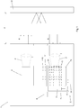
- the measuring device that is the subject of the invention and is suited to measure the distance d of a reference object O, or of a plurality of reference objects O, is represented in Figure 1 , where it is indicated as a whole by 1.
- the measuring device 1 is configured to carry out in succession a plurality of measuring operations A i for the purpose of determining the value of said distance d with great precision.
- the measuring device 1 of the invention comprises emission means 2 suited to emit light radiation R directed towards the reference object O during a predetermined time interval I for each one of said measuring operations A i in sequence.
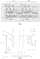
- Said plurality of measuring operations A i in sequence is illustrated in the time chart shown in Figure 2 .
- said emission means 2 are configured to emit, at each time interval I related to each one of the measuring operations A i , light radiation R of the type pulsed with a predefined number X of pulses B, as shown in Figure 2 .
- the emission means 2 they preferably but not necessarily comprise a laser source of the punctiform type. It cannot be excluded, however, that according to different embodiments of the measuring device 1 of the invention, said emission means 2 may comprise a LED source or one or more laser diodes.
- the measuring device 1 that is the subject of the invention furthermore comprises receiving means 3 provided with an area 31 which is sensitive to said light radiation R reflected by the reference object O, as schematically shown in Figure 1 .
- the sensitive area 31 is sensitive to any luminous flux whose photons F impact it.
- the sensitive area 31 is provided with a number M of sensitive units 4, preferably arranged as a matrix in such a way as to define one or more columns and one or more rows.
- each one of said M sensitive units 4 is configured in such a way that it generates an electrical signal S following the impact of at least one photon F on its sensitive surface 41.
- the sensitive area 31 comprises a number L of sensitive units 4.
- the M sensitive units 4 represent, among all the L sensitive units 4, those actually enabled for the generation of said electrical signal S.
- the number M may be less than or equal to the number L.
- alternative embodiments of the measuring device 1 of the invention may not include the possibility to enable the sensitive units 4 or not. Therefore, in this case all of the L sensitive units 4 defined in the sensitive area 31 are enabled. In other words, M coincides with L.
- each one of said L (M if only the enabled ones are taken in consideration) sensitive units 4 comprises a SPAD (Single Photon Avalanche Diode) 81.
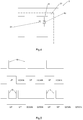
- one or more of said L (M) sensitive units 4 may comprise two SPADs 81 and 82 whose sensitive surfaces have different sizes, as schematically shown in Figure 4 .
- each sensitive unit 4 may comprise more than two SPADs.
- the functionality and the advantages related to the presence of said two SPADs in one or more of the L (M) sensitive units 4 are described in detail here below.
- a further functional component belonging to the measuring device 1 of the invention is a first processing unit 5 which in turn comprises a number N e of processing elements 6, where, according to the invention, N e ⁇ M.
- N e processing elements 6, in particular, is configured so that it receives the electrical signal S generated by one of the M sensitive units 4 and determines the time of impact t of the photon F which impacts the same sensitive unit 4. More precisely, in the measuring device 1 of the invention an exclusive association "one to one" is created between one of the M sensitive units 4 and a processing element 6.
- the time of impact t is the time interval (or ToF) which elapses between the emission of said pulsed light radiation R by the emission means 2 and the impact of at least one of its photons F on the sensitive surface 41 of the specific sensitive unit 4.
- the first processing unit 5 is configured so that it calculates, at the moment of each one of the measuring operations A i , the value of the distance d based on the time of impact t related to at least one of the M sensitive units 4. It will be shortly clear, following the description of the characteristics that distinguish the measuring device 1 of the invention from the known devices, how the number of sensitive units 4 to be taken in consideration for the calculation of said distance d at the moment of each measuring operation A i is defined.
- the first processing unit 5 is configured to actuate processing logics and algorithms of the known type for the determination of a single value of said distance d starting, in fact, from said plurality of electrical signals S.
- the N e processing elements 6 of the first processing unit 5 are N e TDCs (Time-to-Digital Converter) which, as explained above, are capable of measuring the time elapsed between a reference signal (clock) and the time of arrival of the electrical signal S related to said time of impact and of converting said measurement into a digital representation.
- N e TDCs Time-to-Digital Converter
- the first processing unit 5 comprises a further electronic calculation element 51 operatively connected to each one of said N e processing elements 6 and configured, in fact, to calculate said distance d.
- the first processing unit 5 is physically made in the same support in which the sensitive area 31 of said receiving means 3 is defined.
- the first processing unit 5 may be made as an independent element with respect to the receiving means 3, provided that, obviously, it is operatively connected to the latter.
- the N e processing elements 6 may be defined on the same support used for said sensitive area 31, while the electronic calculation element 51 is defined as an independent element.
- the measuring device 1 comprises, furthermore, a second processing unit 7 configured in such a way that at the moment of each one of the measuring operations A i it performs a series of actions which are described below.
- the second processing unit 7 is configured to receive as an input the electrical signals S generated by the M sensitive units 4. More precisely, therefore, the second processing unit 7 is operatively connected to the sensitive area 31 so that it can receive said electrical signals S independently of the first processing unit 5.
- the second processing unit 7 is configured in such a way that, once said electrical signals S have been received, at the end of the emission time interval I for each one of the measuring operations A i , it processes the electrical signals S so as to select a number N u of sensitive units 4 impacted by at least one photon F actually belonging to the light radiation R.
- the second processing unit 7 is configured in such a way that, once said N u sensitive units 4 have been selected, it associates each one of them with one of the N e processing elements 6, so that, at the moment of the successive measuring operation A i+1 , said distance d is determined by said first processing unit 5 based on the time of impact t of at least one photon F related to each one of the N u sensitive units 4 selected.
- a first advantage obtained through said procedure, performed cyclically at the moment of each measuring operation A i consists in the identification of a region of interest comprising one or more sensitive units 4 within the sensitive area 31, on which the impact of the photons F belonging to the light radiation R emitted by the emission means 2 is actually expected to take place.
- a further advantage determined by the fact that the second processing unit 7 is configured so as to cyclically perform, at the moment of each measuring operation A i , said sequence of actions, consists in a periodical adaptation of the position, shape and/or size of said region of interest, constituted by said N u sensitive units 4, when the position of the reference object O with respect to the measuring device 1 varies and/or when the light intensity on the receiving means 3 varies due to a change occurred in the external environmental conditions or in the emitted light radiation R itself.
- the measuring device 1 of the invention is capable of dynamically varying the position, shape and/or size of said region of interest based on the light conditions detected during the previous measuring operation A i-1 for the purpose of improving the signal-to-noise ratio and, consequently, thus increasing precision in the determination of said distance d during each measuring operation A i .
- the second processing unit 7 is configured so as to calculate the number of occurrences related to the impact of at least one photon F, hereinafter indicated by Fp, belonging to the light radiation R for each one of the M sensitive units 4 during the pre-established time interval I related to each measuring operation A i .
- the second processing unit 7 is configured to determine a plurality of histograms, each one of which is related to the events, meaning said number of occurrences, which take place during the emission time interval I on each one of the M sensitive units 4 taken individually or together with other sensitive units 4.
- the processing unit 7, preferably a TDC, associated with said sensitive unit 4 when an event is detected on a sensitive unit 4, the processing unit 7, preferably a TDC, associated with said sensitive unit 4 generates a digital code related to the Time of Flight of said event with respect to a reference signal (clock).
- a reference signal clock
- the second processing unit 7 is configured so that it calculates the occurrences by making in sequence at least one first count UP of said occurrences during the emission of the light radiation R by the emission means 2 and at least one second count DOWN in the absence of said light radiation R.
- the representation of this sequence of steps is schematically shown in Figure 2 .
- the second processing unit 7 is configured in such a way that, following each sequence of at least one first count UP followed by at least one second count DOWN, it deducts the occurrences calculated during said two counts from each other.
- This last action advantageously makes it possible to filter the electrical signals S generated by the impact of photons Fb belonging to the background noise on each one of the M sensitive units 4, thus also allowing the second processing unit 7 to consider, for the calculation of the occurrences, exclusively those electrical signals S generated by the impact of at least one photon Fp actually belonging to the light radiation R.
- the second processing unit 7 is configured to repeat X times the sequence comprising a single first count UP followed by a single second count DOWN, where X represents, as already explained above, the number of pulses B of the light radiation R emitted during the time interval I for each one of the measuring operations A i .
- the measuring device 1 of the invention may be configured so as to make it possible to perform, for each sequence of counts during said time interval I , two or more consecutive first counts UP followed by two or more consecutive second counts DOWN.
- the measuring device 1 may be configured so as to make it possible to choose the number of consecutive first counts UP and the number of consecutive second counts DOWN for each sequence, equal to a power of 2.
- Said possible alternative to the preferred embodiment advantageously assumes considerable importance at the moment when it is necessary to arrange two measuring devices 1 of the invention in adjacent positions. Their closeness, in fact, may cause a mutual interference, as the light radiation R emitted by a first one of said measuring devices 1 may light the receiving means 3 of the second measuring device 1, and vice versa.
- the efficiency of each measuring device in particular the ability to correctly select the N u sensitive units 4, in addition to being negatively influenced by the presence of the background noise due to the environmental conditions, will be further reduced by the presence of the light radiation R emitted by the second one of the two measuring devices 1.
- the invention makes it possible to select, for the two adjacent measuring devices 1, different values for the number of consecutive repetitions of the first counts UP and of the second counts DOWN, with the only restriction that said number, as already said, must be a power of 2.
- the first measuring device 1 is configured so that it repeats several times the sequence comprising a single first count UP followed by a single second count DOWN
- the second measuring device 1 is configured so that it repeats several times the sequence comprising two consecutive first counts UP followed by two consecutive second counts DOWN, as schematically shown in Figure 5 .
- the second processing units 7 and the emission means 2 of both of the measuring devices 1 can be configured so as to repeat the sequence of first counts UP followed by second counts DOWN at random time instants within the emission time interval I. Also in this case, in fact, the non-coincidence of the time instants in which said first and said second counts UP and DOWN are performed in the two adjacent measuring devices 1 makes it possible to eliminate their mutual disturbance.
- this is configured to select, following said determination of the occurrences, the number N u of sensitive units 4 among the M sensitive units 4 based on the decreasing order of said number of occurrences, at the moment of each measuring operation A i .
- a number N u of sensitive units 4 equal to the number N e of processing elements 6 is selected in decreasing order, in such a way as to associate one of the N u sensitive units 4 with each one of the N e processing elements 6.
- the second processing unit 7 may be configured so as to select only the M sensitive units 4 featuring a number of occurrences exceeding a certain pre-established value. In this case, therefore, for each measuring operation A i it would be possible to select a number N u of sensitive units 4 even smaller than the number N e of processing elements 6. In this case, only a number of the N e processing elements 6 equal to N u would be associated with one of the N u sensitive units 4.
- the second processing unit 7 may be configured so as to select, always according to the occurrences, a number N u of sensitive units 4 which is smaller than the number N e of processing elements 6.
- the second processing unit 7 may be configured in such a way that, following said selection, each one of said N e processing elements 6 is associated with one of the N u sensitive units 4 selected or further sensitive units 4 that are in the neighbourhood of one of said N u sensitive units 4, according to a predefined distribution pattern.
- the measuring device 1 of the invention is preferably but not necessarily configured to allow a setting step for the receiving means 3 to be performed.
- said setting step has the purpose of making it possible to set in advance the "enabled” or “disabled” condition of each one of the L sensitive units 4, following which said M sensitive units 4 are selected as the only sensitive units 4 actually enabled for the generation of said electrical signal S.
- enabling a limited number M of sensitive units 4 compared to their total number (L sensitive units 4 ) through said setting step makes it possible to increase the signal-to-noise ratio in a permanent manner and to limit the number of sensitive units 4 to be analysed at the moment of each measuring operation in order to select said N u sensitive units 4.
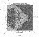
- the number M of enabled sensitive units 4 can be further reduced, as the sensitive units 4 indicated by V in Figure 6 , although lit by the light radiation R when the object O is in a close position with respect to the measuring device 1, do not provide any additional useful information compared to the useful information obtainable from the electrical signals S generated by the sensitive units 4 belonging to the band indicated by U. Therefore, to conclude, the possibility to carry out said setting step makes it possible to identify and enable exclusively a limited number M of sensitive units 4 distributed along said axis Y, thus contributing to increasing said signal-to-noise ratio while at the same time maintaining the quality of the usable information unaltered.
- the measuring device 1 of the invention may not be configured to allow the execution of said setting step and thus to make it possible to set the "enabled” or “disabled” condition of said L sensitive units 4 in advance.
- the measuring device of the invention can be configured in such a way as to allow said setting step to be performed with no need to cyclically select the N u sensitive units 4.
- the corresponding second processing unit 7 is configured in such a way that at the moment of each one of the measuring operations A i said two SPADs 81 and 82 are enabled individually or jointly for each one of said sensitive units 4.
- the second processing unit 7 is configured to enable said two SPADs 81 and 82 individually or jointly based on the number of photons F, that is, on the light intensity, impacting the sensitive area 31 during the previous measuring operation A i-1 .
- the second processing unit 7 is configured to determine said number of photons F based on the electrical signals S generated by the M sensitive units 4 and received as an input by said second processing unit 7.
- This further characteristic advantageously allows the measuring device 1 that is the subject of the invention to dynamically and automatically reset, at the moment of each measuring operation A i , the value of the fill factor for each sensitive unit 4, and therefore the sensitivity of the sensitive area 31 to the light radiation R, based on the intensity of the same and on the background noise, if any, detected in the previous cycle.
- each sensitive unit 4 comprising said two SPADs 81 and 82 a minimum fill factor value is obtained when only the SPAD 81 with smaller sensitive surface is enabled, an intermediate fill factor when only the SPAD 82 with larger sensitive surface is enabled and, finally, a maximum fill factor value when both of the SPADs 81 and 82 are enabled.
- said function of the measuring device 1 of the invention automatically lowers the sensitivity of the M sensitive units 4, consequently avoiding their sudden saturation ("pile-up") and the drastic reduction of the total fill factor value of the receiving means 3.
- the second processing unit 7 may be configured so as to vary, at the moment of each one of the measuring operations A i , the biasing voltage V bias of one or more of the M sensitive units 4 in a manner inversely proportional to the number of photons F impacting the sensitive area 31 during the previous measuring operation A i-1 .
- the measuring device 1 may be configured in such a way as to activate, at the moment of each one of the measuring operations A i , the M sensitive units 4 in different time instants within the pre-established time interval I , based on the spatial coordinates of each one of them at the level of the sensitive area 31.
- activate refers to the command, known as "gating" in technical jargon, which determines the opening of the observation window of each one of the M sensitive units 4 within which a photon F impacting the respective sensitive surface 41 can be detected.
- said observation window will close, in the case of the SPADs, in the instant when said impact takes place.
- this further function of the measuring device 1 of the invention contributes to increasing the signal-to-noise ratio.
- said architecture includes the definition of a first electronic counter 10 and of a second electronic counter 11 shared by all the sensitive units 4 belonging to the same column of the matrix mentioned above.
- said first electronic counter 10 is configured to count the occurrences related to any of said sensitive units 4 of the same column during the first count UP, while the second electronic counter 11 is configured to count said occurrences during the second count DOWN.
- the second processing unit 7 may comprise a first electronic counter 10 and a second electronic counter 11 exclusively associated with each one of the L sensitive units 4. Furthermore, it cannot be excluded that, in different variant embodiments of the measuring device 1 of the invention, there may be a common association of a first and a second electronic counter 10 and 11 with a plurality of sensitive units 4 belonging to a row of said matrix or, in general, belonging to a predefined subarray.
- the second processing unit 7 comprises, furthermore, an electronic calculation element 71 operatively connected to said electronic counters 10 and 11 and configured to receive as an input the results of said counts UP and DOWN and to perform the successive subtraction calculation.
- the second processing unit 7 comprises switching connection means 72, defined “switching matrix" in technical jargon, operatively connected between said plurality of L sensitive units 4 and the N e processing elements 6.
- the electronic calculation element 71 is configured so that it controls said switching connection means 72 in such a way as to enable an electrical connection between one of the N u sensitive units 4 and one of the N e processing elements 6 based on the settings stored in said storage register 9 during the setting step and based on the number of said occurrences related to the specific sensitive unit 4.
- the invention includes also the method for measuring the distance d of at least a reference object O, implemented by means of the measuring device 1 of the invention.
- a plurality of measuring operations A i is carried out in sequence, wherein each one of said measuring operations A i includes the emission, through said emission means 2, of a light radiation R directed towards the reference object O for a predetermined time interval I.
- an electrical signal S is generated by means of each one of the M sensitive units 4, following the impact of at least one photon Fp on the respective sensitive surface 41.
- the value of the distance d is determined by means of said first processing unit 5, based on the time of impact t of said photon Fp on at least one of the M sensitive units 4, where the time of impact t is determined by at least one of the N e processing elements 6 associated with said sensitive unit 4.
- the electrical signals S of all of the M enabled sensitive units 4 are processed by means of the second processing unit 7, for each one of the measuring operations A i , in such a way as to select, among said M sensitive units 4, a number N u of sensitive units 4 on which at least one photon Fp belonging to the light radiation R reflected by the reference element O actually impacted.
- each one of the N u sensitive units 4 selected is associated with one of the N e processing elements 6 in such a way that at the moment of the successive measuring operation A i+1 the value of the distance d is determined based on the time of impact t of at least one of the photons Fp related to each one of said N u sensitive units 4 selected.
- the method of the invention can preferably but not necessarily comprise the further operating steps illustrated in detail in the description of the measuring device 1 according to the preferred embodiment or according to the variant embodiments previously described.
- the measuring device and the measuring method that are the subjects of the invention achieve all the set objects.
- the invention achieves the object to provide a measuring device that is capable of maintaining a high signal-to-noise ratio in any operating condition, even in the presence of a high luminous flux.
- the invention achieves the object to provide a measuring device that is capable of determining with high precision the value of the distance between the same device and a reference object even in the presence of a high luminous flux.
- the invention also achieves the object to provide a measuring device that is capable of maintaining high precision in the determination of said distance even in case of a sudden change in the external measuring conditions.
- the invention also achieves the object to provide a measuring device with a high static and dynamic fill factor.
- the invention also achieves the object to provide a measuring device with limited size and simplified architecture.
- the invention also achieves the object to provide a measuring device that requires moderate energy consumption.
Priority Applications (4)
| Application Number | Priority Date | Filing Date | Title |
|---|---|---|---|
| EP17180791.0A EP3428574A1 (fr) | 2017-07-11 | 2017-07-11 | Dispositif de mesure de distance et procédé de mesure de ladite distance |
| US16/031,640 US11079479B2 (en) | 2017-07-11 | 2018-07-10 | Device for measuring a distance and method for measuring said distance |
| JP2018130963A JP6761001B2 (ja) | 2017-07-11 | 2018-07-10 | 距離を計測するための装置及び前記距離を計測するための方法 |
| CN201810759020.5A CN109239724B (zh) | 2017-07-11 | 2018-07-11 | 用于测量距离的设备和用于测量所述距离的方法 |
Applications Claiming Priority (1)
| Application Number | Priority Date | Filing Date | Title |
|---|---|---|---|
| EP17180791.0A EP3428574A1 (fr) | 2017-07-11 | 2017-07-11 | Dispositif de mesure de distance et procédé de mesure de ladite distance |
Publications (1)
| Publication Number | Publication Date |
|---|---|
| EP3428574A1 true EP3428574A1 (fr) | 2019-01-16 |
Family
ID=59409156
Family Applications (1)
| Application Number | Title | Priority Date | Filing Date |
|---|---|---|---|
| EP17180791.0A Withdrawn EP3428574A1 (fr) | 2017-07-11 | 2017-07-11 | Dispositif de mesure de distance et procédé de mesure de ladite distance |
Country Status (4)
| Country | Link |
|---|---|
| US (1) | US11079479B2 (fr) |
| EP (1) | EP3428574A1 (fr) |
| JP (1) | JP6761001B2 (fr) |
| CN (1) | CN109239724B (fr) |
Families Citing this family (12)
| Publication number | Priority date | Publication date | Assignee | Title |
|---|---|---|---|---|
| US10620300B2 (en) | 2015-08-20 | 2020-04-14 | Apple Inc. | SPAD array with gated histogram construction |
| US20180341009A1 (en) | 2016-06-23 | 2018-11-29 | Apple Inc. | Multi-range time of flight sensing |
| WO2019005260A1 (fr) | 2017-06-29 | 2019-01-03 | Apple Inc. | Cartographie de profondeur de temps de vol à compensation de parallaxe |
| US10955552B2 (en) | 2017-09-27 | 2021-03-23 | Apple Inc. | Waveform design for a LiDAR system with closely-spaced pulses |
| EP3704510B1 (fr) | 2017-12-18 | 2022-10-05 | Apple Inc. | Détection de temps de vol à l'aide d'un réseau d'émetteurs adressable |
| WO2020167338A1 (fr) * | 2019-02-11 | 2020-08-20 | Apple Inc. | Détection de profondeur à l'aide d'un réseau épars de faisceaux pulsés |
| CN110221272B (zh) * | 2019-05-09 | 2021-11-19 | 奥比中光科技集团股份有限公司 | 时间飞行深度相机及抗干扰的距离测量方法 |
| US11500094B2 (en) | 2019-06-10 | 2022-11-15 | Apple Inc. | Selection of pulse repetition intervals for sensing time of flight |
| US11555900B1 (en) | 2019-07-17 | 2023-01-17 | Apple Inc. | LiDAR system with enhanced area coverage |
| US11733359B2 (en) | 2019-12-03 | 2023-08-22 | Apple Inc. | Configurable array of single-photon detectors |
| CN112611368B (zh) * | 2020-12-01 | 2022-08-05 | 西南交通大学 | 一种大地精密检测仪自动对齐信标装置 |
| US11681028B2 (en) | 2021-07-18 | 2023-06-20 | Apple Inc. | Close-range measurement of time of flight using parallax shift |
Citations (5)
| Publication number | Priority date | Publication date | Assignee | Title |
|---|---|---|---|---|
| US20030128351A1 (en) * | 2001-06-26 | 2003-07-10 | Dierk Schmidt | Device for optical distance measurement of distance over a large measuring range |
| US20090009747A1 (en) * | 2006-03-23 | 2009-01-08 | Peter Wolf | Device for Optically Measuring Distance and Method for Operating Said Type of Device |
| US20130015331A1 (en) * | 2011-07-12 | 2013-01-17 | Leica Microsystems Cms Gmbh | Device and method for detecting light |
| US8773642B2 (en) | 2009-09-11 | 2014-07-08 | Robert Bosch Gmbh | Optical distance measuring device |
| EP3182154A1 (fr) * | 2015-12-20 | 2017-06-21 | Apple Inc. | Réseau spad avec commande de polarisation au niveau pixel |
Family Cites Families (13)
| Publication number | Priority date | Publication date | Assignee | Title |
|---|---|---|---|---|
| EP1522870B1 (fr) * | 2003-10-06 | 2013-07-17 | Triple-IN Holding AG | Mesure de distance |
| EP2028509A1 (fr) * | 2007-08-09 | 2009-02-25 | European Organisation for Nuclear Research CERN | Dispositif de surveillance de radiations |
| US8476594B2 (en) * | 2008-12-15 | 2013-07-02 | Koninklijke Philips Electronics N.V. | Temperature compensation circuit for silicon photomultipliers and other single photon counters |
| EP2404196B1 (fr) * | 2009-03-06 | 2013-10-16 | Koninklijke Philips N.V. | Circuit de commande et de compensation de température pour des compteurs de photon unique |
| DE102009029372A1 (de) * | 2009-09-11 | 2011-03-24 | Robert Bosch Gmbh | Messvorrichtung zur Messung einer Entfernung zwischen der Messvorrichtung und einem Zielobjekt mit Hilfe optischer Messstrahlung |
| TWI559763B (zh) * | 2009-10-01 | 2016-11-21 | 索尼半導體解決方案公司 | 影像取得裝置及照相機系統 |
| MX2014001272A (es) * | 2011-08-03 | 2014-05-19 | Koninkl Philips Nv | Modos de lectura sensibles a posicion para arreglos fotomultiplicadores de silicio digitales. |
| US9280283B2 (en) * | 2013-10-28 | 2016-03-08 | Blackberry Limited | Contactless gesture recognition with sensor having asymmetric field of view |
| US9874629B2 (en) * | 2013-12-23 | 2018-01-23 | Oulun Yliopisto | Distance measurement device, receiver thereof and method of distance measurement |
| US9819930B2 (en) * | 2015-05-26 | 2017-11-14 | Omnivision Technologies, Inc. | Time of flight imaging with improved initiation signaling |
| US10324171B2 (en) * | 2015-12-20 | 2019-06-18 | Apple Inc. | Light detection and ranging sensor |
| WO2017112416A1 (fr) * | 2015-12-20 | 2017-06-29 | Apple Inc. | Capteur de détection de lumière et de télémétrie |
| US20180341009A1 (en) * | 2016-06-23 | 2018-11-29 | Apple Inc. | Multi-range time of flight sensing |
-
2017
- 2017-07-11 EP EP17180791.0A patent/EP3428574A1/fr not_active Withdrawn
-
2018
- 2018-07-10 US US16/031,640 patent/US11079479B2/en active Active
- 2018-07-10 JP JP2018130963A patent/JP6761001B2/ja active Active
- 2018-07-11 CN CN201810759020.5A patent/CN109239724B/zh active Active
Patent Citations (5)
| Publication number | Priority date | Publication date | Assignee | Title |
|---|---|---|---|---|
| US20030128351A1 (en) * | 2001-06-26 | 2003-07-10 | Dierk Schmidt | Device for optical distance measurement of distance over a large measuring range |
| US20090009747A1 (en) * | 2006-03-23 | 2009-01-08 | Peter Wolf | Device for Optically Measuring Distance and Method for Operating Said Type of Device |
| US8773642B2 (en) | 2009-09-11 | 2014-07-08 | Robert Bosch Gmbh | Optical distance measuring device |
| US20130015331A1 (en) * | 2011-07-12 | 2013-01-17 | Leica Microsystems Cms Gmbh | Device and method for detecting light |
| EP3182154A1 (fr) * | 2015-12-20 | 2017-06-21 | Apple Inc. | Réseau spad avec commande de polarisation au niveau pixel |
Also Published As
| Publication number | Publication date |
|---|---|
| US20190018118A1 (en) | 2019-01-17 |
| US11079479B2 (en) | 2021-08-03 |
| CN109239724A (zh) | 2019-01-18 |
| CN109239724B (zh) | 2023-04-28 |
| JP6761001B2 (ja) | 2020-09-23 |
| JP2019049531A (ja) | 2019-03-28 |
Similar Documents
| Publication | Publication Date | Title |
|---|---|---|
| US11079479B2 (en) | Device for measuring a distance and method for measuring said distance | |
| KR102604902B1 (ko) | 펄스형 빔들의 희소 어레이를 사용하는 깊이 감지 | |
| KR102403544B1 (ko) | 방출기들의 어드레스가능 어레이를 사용하는 비행 시간 감지 | |
| US9176241B2 (en) | Position-sensitive readout modes for digital silicon photomultiplier arrays | |
| JP6665873B2 (ja) | 光検出器 | |
| US11644551B2 (en) | Lidar systems with improved time-to-digital conversion circuitry | |
| EP3516415A1 (fr) | Commande de puissance de transmission adaptative pour lidar | |
| CN110520756B (zh) | 光学测量装置 | |
| GB2505705A (en) | Circuit for combining signals comprising a plurality of edge detectors | |
| US20240111049A1 (en) | Method for gating an output of a single photon avalanche diode (spad) cluster based on an ambient count of ambient light events generated by the spad cluster in a region of interest of a time of flight (tof) | |
| WO2018190276A1 (fr) | Dispositif de mesure optique | |
| CN110865384B (zh) | 测距装置 | |
| KR102501237B1 (ko) | 광 신호의 수신을 위한 수신 장치 | |
| US10627214B2 (en) | Method for electronically analyzing a signal changing over time | |
| US11815393B2 (en) | Image sensor including photodiode array comprising a first transistor coupled to a photodiode to receive a column enable signal and a second transistor coupled to the photodiode to receive a column disable signal | |
| US20210088661A1 (en) | Photodetector and optical ranging apparatus using the same | |
| US20170090029A1 (en) | Method of detecting an object | |
| JP6102225B2 (ja) | レインセンサ | |
| CN113994228A (zh) | 读取装置和激光雷达测量装置 | |
| KR20220123308A (ko) | 광학 런타임 측정 중에 확산 후방 산란을 결정하기 위한 후방 산란 히스토그램 데이터 생성 장치 및 방법 | |
| WO2024095201A1 (fr) | Dispositif amélioré pour mesure de distance entre ledit dispositif et un objet de référence à l'aide d'un rayonnement lumineux | |
| CN115201781A (zh) | 激光雷达传感器和从其中去除噪声的方法 | |
| CN114089354A (zh) | 探测装置及方法 | |
| CN115685227A (zh) | 一种探测方法 |
Legal Events
| Date | Code | Title | Description |
|---|---|---|---|
| PUAI | Public reference made under article 153(3) epc to a published international application that has entered the european phase |
Free format text: ORIGINAL CODE: 0009012 |
|
| STAA | Information on the status of an ep patent application or granted ep patent |
Free format text: STATUS: THE APPLICATION HAS BEEN PUBLISHED |
|
| AK | Designated contracting states |
Kind code of ref document: A1 Designated state(s): AL AT BE BG CH CY CZ DE DK EE ES FI FR GB GR HR HU IE IS IT LI LT LU LV MC MK MT NL NO PL PT RO RS SE SI SK SM TR |
|
| AX | Request for extension of the european patent |
Extension state: BA ME |
|
| STAA | Information on the status of an ep patent application or granted ep patent |
Free format text: STATUS: REQUEST FOR EXAMINATION WAS MADE |
|
| 17P | Request for examination filed |
Effective date: 20190214 |
|
| RBV | Designated contracting states (corrected) |
Designated state(s): AL AT BE BG CH CY CZ DE DK EE ES FI FR GB GR HR HU IE IS IT LI LT LU LV MC MK MT NL NO PL PT RO RS SE SI SK SM TR |
|
| STAA | Information on the status of an ep patent application or granted ep patent |
Free format text: STATUS: EXAMINATION IS IN PROGRESS |
|
| 17Q | First examination report despatched |
Effective date: 20190711 |
|
| STAA | Information on the status of an ep patent application or granted ep patent |
Free format text: STATUS: THE APPLICATION IS DEEMED TO BE WITHDRAWN |
|
| 18D | Application deemed to be withdrawn |
Effective date: 20191122 |