EP2002208B1 - Dispositif de mesure optique de distances et son procédé de fonctionnement - Google Patents
Dispositif de mesure optique de distances et son procédé de fonctionnement Download PDFInfo
- Publication number
- EP2002208B1 EP2002208B1 EP07704446.9A EP07704446A EP2002208B1 EP 2002208 B1 EP2002208 B1 EP 2002208B1 EP 07704446 A EP07704446 A EP 07704446A EP 2002208 B1 EP2002208 B1 EP 2002208B1
- Authority
- EP
- European Patent Office
- Prior art keywords
- detector
- light
- measuring
- target object
- distance
- Prior art date
- Legal status (The legal status is an assumption and is not a legal conclusion. Google has not performed a legal analysis and makes no representation as to the accuracy of the status listed.)
- Active
Links
Images

Classifications
-
- G—PHYSICS
- G01—MEASURING; TESTING
- G01C—MEASURING DISTANCES, LEVELS OR BEARINGS; SURVEYING; NAVIGATION; GYROSCOPIC INSTRUMENTS; PHOTOGRAMMETRY OR VIDEOGRAMMETRY
- G01C3/00—Measuring distances in line of sight; Optical rangefinders
- G01C3/02—Details
- G01C3/06—Use of electric means to obtain final indication
- G01C3/08—Use of electric radiation detectors
-
- G—PHYSICS
- G01—MEASURING; TESTING
- G01S—RADIO DIRECTION-FINDING; RADIO NAVIGATION; DETERMINING DISTANCE OR VELOCITY BY USE OF RADIO WAVES; LOCATING OR PRESENCE-DETECTING BY USE OF THE REFLECTION OR RERADIATION OF RADIO WAVES; ANALOGOUS ARRANGEMENTS USING OTHER WAVES
- G01S17/00—Systems using the reflection or reradiation of electromagnetic waves other than radio waves, e.g. lidar systems
- G01S17/02—Systems using the reflection of electromagnetic waves other than radio waves
- G01S17/06—Systems determining position data of a target
- G01S17/08—Systems determining position data of a target for measuring distance only
-
- G—PHYSICS
- G01—MEASURING; TESTING
- G01S—RADIO DIRECTION-FINDING; RADIO NAVIGATION; DETERMINING DISTANCE OR VELOCITY BY USE OF RADIO WAVES; LOCATING OR PRESENCE-DETECTING BY USE OF THE REFLECTION OR RERADIATION OF RADIO WAVES; ANALOGOUS ARRANGEMENTS USING OTHER WAVES
- G01S7/00—Details of systems according to groups G01S13/00, G01S15/00, G01S17/00
- G01S7/48—Details of systems according to groups G01S13/00, G01S15/00, G01S17/00 of systems according to group G01S17/00
- G01S7/481—Constructional features, e.g. arrangements of optical elements
- G01S7/4816—Constructional features, e.g. arrangements of optical elements of receivers alone
-
- G—PHYSICS
- G01—MEASURING; TESTING
- G01S—RADIO DIRECTION-FINDING; RADIO NAVIGATION; DETERMINING DISTANCE OR VELOCITY BY USE OF RADIO WAVES; LOCATING OR PRESENCE-DETECTING BY USE OF THE REFLECTION OR RERADIATION OF RADIO WAVES; ANALOGOUS ARRANGEMENTS USING OTHER WAVES
- G01S17/00—Systems using the reflection or reradiation of electromagnetic waves other than radio waves, e.g. lidar systems
- G01S17/02—Systems using the reflection of electromagnetic waves other than radio waves
- G01S17/06—Systems determining position data of a target
- G01S17/08—Systems determining position data of a target for measuring distance only
- G01S17/32—Systems determining position data of a target for measuring distance only using transmission of continuous waves, whether amplitude-, frequency-, or phase-modulated, or unmodulated
Definitions
- the invention relates to a device for optical distance measurement according to the preamble of the independent claim.
- optical distance measuring devices have been known for some time and in the meantime are also sold commercially in large numbers. These devices emit a modulated light beam that is aligned with the surface of a desired target object whose distance from the device is to be determined. The returning light reflected or scattered by the targeted target object is partially re-detected by the device and used to determine the searched distance.
- rangefinders generally includes distances in the range of a few centimeters to several hundred meters.
- optical distance measuring devices can basically be divided into two categories according to the arrangement of necessarily present in the device transmitting or receiving channels.
- the transmission channel is arranged at a certain distance from the receiving channel, so that the respective optical axes parallel to each other, but spaced from each other.
- monoaxial measuring devices in which the receiving channel runs coaxially to the transmission channel.
- the first-mentioned biaxial measuring systems have the advantage that there is no need for complex radiation division for selecting the returning measuring signal, so that, for example, optical crosstalk from the transmitting channel directly into the receiving channel can be better suppressed.
- the detected measuring signal can go to zero.
- a device for optical distance measurement over a large measuring range which has a transmitting unit with a light source for emitting modulated optical radiation towards a target object, the receiving unit arranged in this measuring device having an optical detector for receiving the optical radiation returning from the target object a spaced apart from the optical axis of the transmitting unit receiving axis is located.
- the active, photosensitive surface of the detector of the receiving unit of DE 10 130 763 A1 tapers in the direction of a beam shift for decreasing target object distances, which results from a parallax of the returning measurement radiation.
- a basically comparable device is EP 0 837 301 A2 refer to.
- a device for optical distance measurement is known, which has a plurality of separately activatable photosensitive surfaces.
- a near-and far-range laser range finder having a dedicated receiver having a transmit and receive channel is known.
- the transmission channel consists of a transmission lens, in the focal point of which a laser light source is arranged
- the reception channel consists of a reception objective in whose focal plane a receiver arrangement is located.
- the optical axes of the transmitting lens and the receiving lens are parallel to each other with a finite distance.
- the receiver arrangement of the laser rangefinder of the DE 100 51 302 A1 is a photodiode array with at least two active photodiode areas arranged on a straight line intersecting the optical axes of the transmitting and receiving objectives of this device.
- the object of the present invention is, starting from the state of the art in a device for optical distance measurement, to ensure that a reception signal that is as constant as possible can be measured over the largest possible measuring range.
- the device according to the invention for optical distance measurement has a transmitting unit with a light source for emitting optical radiation, in particular modulated optical measuring radiation, and a receiving unit spaced apart from the optical axis of this transmitting unit with at least one optical detector.
- the detector of the receiving unit advantageously has a plurality of separate, in particular electrically separate, photosensitive surfaces, which can be activated separately from one another during operation of the device.
- the envelope expands in the direction of the beam displacement for decreasing target object distances, which results from a parallax of the returning radiation. This can then compensate in particular for the effect of the enlarged measuring beam diameter for smaller object distances.
- the envelope is a hypothetical curve that can be placed with minimal distance around the edge of the photosensitive surfaces of the detector. In this way it can be ensured that for each object distance sufficient measurement signal falls on the currently active partial area of the detector.
- the shape of the entire optical detection surface is selected so that there is sufficient signal amplitude on the detector surface even in the near field. This leads to a further improvement of the ratio from useful light to extraneous light, so that the measuring accuracy of the device is increased in the immediate vicinity and therefore the measuring range accessible to the device is also extended for this reason.
- the photosensitive surface of an optical detector which typically consists of at least one semiconductor material, can be activated. That is, light incident on the photosensitive surface of the detector is typically converted into an electrical signal and can thus be detected via a downstream electronic circuit.
- the device according to the invention has switching means which make it possible to switch on or off individual or several subareas of the photosensitive surface of the detector.
- the noise which is generated in principle due to impinging on the detector extraneous light can be significantly reduced, since only those photosensitive surfaces are used, which is incident on the useful light for the measurement essential.
- only a single photosensitive surface can be activated in an advantageous manner.
- the photodiode can be operated at a higher frequency, which in turn leads to a higher measurement accuracy of the device according to the invention for optical distance measurement.
- the device according to the invention has means which make it possible to switch on or off individual light-sensitive surfaces of the detector.
- the activation of the respective photosensitive surface can take place, for example, in that for each surface - with a common mass - a connection to the outside, d. H. for example, out of the diode housing.
- d. H. for example, out of the diode housing.
- it can be influenced by contacting the corresponding terminal, which surface should be activated and thus used.
- the envelope of the light-sensitive surfaces of the detector tapers in the direction of a beam displacement for decreasing target object distances, which results from parallax of the returning radiation.
- the envelope of the photosensitive surfaces of the detector advantageously has an axis of symmetry lying in the common plane of the optical axes of the transmitting unit and receiving unit of the apparatus. Due to the fact that the measuring beam returning from the target object becomes laterally in the common space for a decreasing object distance Level of the optical axes of transmitting unit and receiving unit emigrates, the detector will advantageously have an elongated shape in this direction. In this way the dependence of the direction of the returning measuring signal on the distance of the measuring device from a target object is taken into account.
- the size of the light-sensitive surfaces of the detector of the receiving unit is chosen so that enough signal, for example, in the vicinity, falls on the respective active partial surface of the detector.
- the return measurement signal for the near range is significantly larger than for target objects that are far away from the measurement device.
- the extension of the envelope of all light-sensitive surfaces of the detector perpendicular to the common plane of the optical axes of the transmitting and receiving unit can therefore decrease as the light signal increases due to the shorter running distance in the near range.
- This also has the advantage that, due to the reduced extent of the detector, although sufficient light from the near zone falls on the detector, but that the detector can not be overridden by the light from the near range due to its smaller in this direction active photosensitive surfaces.
- a detector is advantageous in which the envelope of the photosensitive subareas of the detector does not taper in the direction of the beam displacement for shorter object distances, but just expands.
- the size of the area of the detector or the size of the individual sensitive subareas of the detector should only ensure that the effective area, ie an active area in the area of the detector, by striking light from far away target objects on the detector surface, becomes large enough is, in this case as far as possible to detect the entire signal, since distant measuring objects to a relatively weak detection signal to lead. This is also a consequence of the law of square law, which is subject to the detected intensity.
- the lateral extent of the active areas of the detector should be correspondingly so large that enough light from the immediate vicinity of the detection reaches the respectively active detection area. Due to the high signal level, which results from the short distances in the near range, it is not necessary in this case to detect the full signal strength.
- Another advantage of the claimed device is that the electrical capacitive properties of the detector of the measuring device are positively influenced due to the inventive form of the active detection surfaces. Too large an active detector surface would increase the electrical capacitance of the detector, so that the time response characteristic, or equivalently the frequency response of the measuring system would no longer meet the required requirements of the time or frequency resolution of the measuring system.
- the inventive device for optical distance measurement can be realized by the use of a laser, in particular a laser diode as a light source.
- Lasers and in particular laser diodes are meanwhile available at low cost over the entire visible spectral range of the electromagnetic waves.
- laser diodes because of their compact size and also relatively high output powers, are suitable for use in optical distance measuring devices, especially in such hand-held devices.
- the device according to the invention for optical distance measurement thus enables the most constant possible reception or detection signal over a large measuring range of distances between the device and a target object.
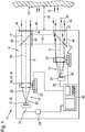
- FIG. 1 Shown schematically is a device according to the invention for optical distance measurement with the most important components for describing their function.
- the device 10 according to the invention has a housing 11 in which a transmitting device 12 for generating a measurement signal 13 and a receiving device 14 for detecting the return of a target object 15 measuring signal 16 are arranged.
- the transmitting device 12 includes a light source 17, which is realized in the embodiment of Figure 1 by a semiconductor laser diode 18.
- the laser diode 18 emits a laser beam 20 in the form of a light beam 22 visible to the human eye.
- the laser diode 18 is operated via a control unit 24, which generates a modulation of the electrical input signal 19 of the diode 18 by a corresponding electronics.
- a control unit 24 which generates a modulation of the electrical input signal 19 of the diode 18 by a corresponding electronics.
- the laser beam 20 then passes through a collimating lens 26 in the form of a lens 28, which in the FIG. 1 is shown in a simplified manner in the form of a single lens 30.
- the objective 28 is optionally located on an adjustment mimic 32, which in principle makes it possible to change the position of the objective in all three spatial directions, for example for adjustment purposes.
- the collimating optics 26 may also already be part of the laser diode 18 or be permanently connected thereto.
- the transmitting branch 12 of the device according to the invention there is also a preferably switchable beam deflection 40, which allows the measuring signal 13, bypassing a target object directly, ie to redirect device internally to the receiving unit 14 of the device 10. In this way, a device-internal reference path 42 is generated, which allows a calibration or a comparison of the measuring system.
- the measuring beam 13 leaves the housing 11 of the device according to the invention through an optical window 44 in the end wall 45 of the device 10.
- the opening of the optical window can be secured, for example, by a shutter 46.
- the actual measurement is the Measuring device 10 then aligned to a target object 15, the distance 48 is to be determined to the meter.
- the signal 16 reflected or also scattered at the desired target object 15 forms a returning beam 49 or 50 which, to a certain extent, returns to the measuring device 10.
- the returning measuring radiation 16 is coupled into the measuring device and in the embodiment of FIG. 1 directed to a receiving optics 52.
- FIG. 1 By way of example, two returning measuring radiation beams 49 and 50 for two different target object distances 48 are shown for clarification.
- the signal returning from the target object 16 falls parallel to the optical axis 51 of the receiving device 14.
- This case is in the embodiment of FIG. 1 represented by the measuring beam 49.
- the returning signal 16 incident in the measuring device is inclined more and more with respect to the axis 51 of the receiving unit 14 due to parallax.
- the beam 50 drawn drawn.
- the receiving optics 52 which in the embodiment of the FIG. 1 also symbolized only schematically by a single lens collimates the returning measurement signal 16 and focuses its beam on the photosensitive surface 66 of a receiving detector 54.
- the detector 54 has for detecting the optical measuring radiation at least one photodiode, such as a PIN diode or an APD (Avalanche Photo Diode) or at least a CCD chip as a photosensitive element 66 on.
- APD Anavalanche Photo Diode
- CCD chip photosensitive element 66
- other surface detectors known in the art as a reception detector are possible.
- the area detector is usually aligned with its active photosensitive surfaces 66 perpendicular to the optical axis of the receiving branch.
- the incident optical signal is converted by the reception detector 54 into an electrical signal 55 and supplied to the further evaluation in an evaluation unit 36 of the device according to the invention.
- the receiving optics 52 which in the embodiment of the FIG. 1 not restrictively also mounted on a Verstellmimik 53 is located approximately at a distance of its focal length from the active surface 66 of the detector, so that incident radiation, which comes from a target object, which is far away from the meter, is focused exactly on the detector or on the active photosensitive surfaces.
- the imaging position for the measuring spot reflected or scattered on the target object is increasingly away from the focus of the receiving lens.
- the returning measuring beam moves with decreasing distance of the target object to the measuring device always further away from the optical axis of the receiving device and thus deviates more and more from the optical axis of the transmitting device.
- the returning measuring beam beam is no longer focused exactly on the detector surface due to the changed imaging conditions on the receiving lens. As the target distance becomes shorter, an increasingly larger spot on the detector surface results.
- the meter of course also has a control and evaluation unit 36.
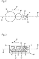
- FIG. 2 a plan view of a detector surface 64 according to the prior art in the direction of the returning from the measurement object measurement signal 16.
- the reference numeral 56 is the common plane of the optical axis 38 of the transmitting unit 12 with the optical axis 51 of the receiving unit 14.
- Der Measurement spot 58 of the returning radiation 16 for very large object distances 48 lies on the optical axis 51 of the receiving unit 14 and is focused on the surface 64 of the detector into a small spot.
- FIG. 2 To illustrate the relationships, a "classic" detector surface 64 of a detector according to the prior art is shown in dashed lines.
- the returning signal 16 falls increasingly obliquely on the receiving objective 52, so that the measuring spot on the detector surface in the direction of arrow 61 in FIG FIG. 2 emigrated.
- FIG. 2 also drawn measuring spot 60 for a small object distance 48 of the target object 15 from the measuring device 10 has thus migrated away from the optical axis 51 of the receiving device and significantly increased in its extent, in particular lateral extent.
- a measuring spot 62 of the returning measurement signal 16 which is again significantly increased and also comes further from the optical axis 51 of the receiving unit 14 to lie.
- Such a displacement of the measuring spot to be detected with the relative distance 48 of a measuring object 15 to the measuring device 10 may possibly lead to the return signal 16 no longer falling on the active surface of the measuring receiver 54 for very small object distances, as indicated by the above , dashed area 64 of a "classic" measuring receiver in FIG. 2 should be indicated.
- the active, photosensitive surface 66 of the detector 54 is designed accordingly and will be described below.
- FIG. 3 shows a first embodiment of the photosensitive surface 66 of a detector of a device according to the invention.
- the detector 54 of the receiving unit 14 in this case has a plurality of photosensitive surfaces 70, 72 and 74, which are separate from each other and form in their entirety the photosensitive surface 66 of the detector.
- the light-sensitive areas of the detector are electrically separated from each other, so that it is possible to switch only one of the photosensitive surfaces 70-74 active, ie, for example, to occupy a voltage signal, so that incident light is converted into an electrical signal.
- the partial surfaces 70, 72 and 74 of the detector can in particular all have the same size, ie area, or else have a different size.
- a connection can be led out of the diode housing, for example, for each surface, so that the respective photosensitive subelement can be activated and selectively used by appropriate contacting or activation of such a terminal.
- This is due to the symbolically represented, electrical connecting lines 57 in the FIGS. 3 to 8 indicated.
- corresponding switching means are provided which make it possible, depending on a corresponding control signal, the respective preferred partial area or Part surfaces of the detector 54 to activate.
- a multiplexer could also be integrated directly into the detector 54, for example into a photodiode.
- the measuring spot 58 comes to lie completely on the photosensitive partial surface 70.
- the photosensitive surface 70 would be actively switched by appropriate circuit means, so that it acts as a detector surface and transferred the optical measurement signal into an electrical measurement signal.
- the likewise present partial surfaces 72 and 74 of the detector are not activated, for example there is no voltage applied to these photosensitive surfaces, so that light which occurs on these surfaces does not contribute to the generation of an electrical signal. If, therefore, extraneous light, which come from other objects that are closer to the meter than the currently measured object 15 in the meter, so this extraneous light would be due to the non-activated, d. H. not turned on photosensitive surfaces 72 and 74 also not detected. This extraneous light would thus also not lead to an increased background noise compared to the measurement signal of the active surface 70 generated by the measuring beam 58.
- the active surface 70 which is activated in particular for very large measuring distances, advantageously has such a lateral extent in the detection plane that it ensures that the measuring spot 58 of the measuring radiation 16 returning from such a far away target object resp. 49 is completely detected.
- a lateral direction is understood to mean a direction perpendicular to the measuring signal direction. Therefore, the dimension of the photosensitive areas 70 should be substantially equal to or slightly larger than the dimensions of a measurement spot 58 for very large object distances. If the measuring spot now moves with decreasing object distance 48 in the direction of the arrow 61 from the original receiving axis 51, then, as in FIG FIG. 2 indicated, the diameter or the lateral dimensions of the measuring spot.
- the lateral direction here is the direction perpendicular to the direction 61, in which the measuring beam emigrates.
- the area detector as a whole has an elongated shape.
- the expansion in the direction of the emigration of the measurement signal is greater, in particular significantly greater, than in orthogonal, i. lateral direction.
- the noise can thus be significantly reduced by extraneous light, since only the part of the area of the detector is used, on which the useful light impinges optimized. Those areas of the detector, which have a relatively high amount of extraneous light, are switched off accordingly.
- only one light-sensitive area of the detector is always active, in particular in this embodiment.
- a plurality of sub-areas may also be activated, in particular when the measurement signal impinges simultaneously on a plurality of subareas and, for example, the sum signal of two subareas is less noisy than the signal of the subareas considered individually. In this case, several partial areas of the detector can be activated according to the invention.
- a short test measurement can be carried out, for example, only for determining the signal components on the individual photosensitive surfaces of the detector of the receiving unit before the actual distance measurement serves. During this test measurement, all or even a plurality of the light-sensitive partial areas of the optical detector can then be briefly activated via the correspondingly provided switching means and, in particular, read out individually.
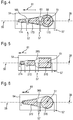
- FIG. 4 1 shows a non-inventive embodiment of a detector 54, in which an envelope 165, which can be drawn around the photosensitive surfaces of the detector, in the direction 61, ie in the direction of emigrating the returning measuring beam for a shorter Meß réelleabstand, rejuvenated.
- the extent of the light-sensitive surfaces 170, 172 or 174 of the detector in the direction perpendicular to the optical axis 51 of the receiving unit 14 is again at least so great that the measuring beam returning from a target object 15 in the near zone at least partially still touches the photosensitive surface 174 falls.
- the light-sensitive area 174 which is used at such distances, may possibly be selected to be significantly lower due to the significantly increased light intensity according to the square law of the square.
- the electrical capacitance of the detector is reduced, so that the temporal response characteristic or, analogously, the frequency response of the measuring system can be significantly increased.
- the envelope 165 which can be drawn around the photosensitive surfaces of the detector in the detector plane, is tapered in the direction 61 of a beam displacement for decreasing target object distances 48. Such an envelope 165 is in FIG. 4 also marked.
- the envelope essentially follows the boundary of the photosensitive subareas, the course of the envelope being interpolated in the direction of the arrow 61, ie, in the direction of a beam shift for decreasing target object distances between two subareas.
- Both the shapes of the photosensitive surfaces and their number within a detector may vary depending on the embodiment. So shows FIG. 5 a detector having a plurality of light-sensitive surfaces 270,272,274 of different sizes formed as rectangles, whose envelope 265 in turn tapers in the direction 61 of a beam shift for decreasing target object distances 48.
- the photosensitive surfaces 270, 272, 274 can, according to the invention, in turn be individually activated during a distance measurement, ie switched on or off.
- FIG. 6 shows a further embodiment with only two separate photosensitive surfaces 370 and 372, however, which are also individually activated according to the principle described above.
- the envelope which can be placed around the photosensitive surfaces of the detector, widens in the direction of shorter object distances.
- Such an embodiment with in the direction 61 expanding envelope, as exemplified in FIG. 7 and FIG. 8 has the advantage that it takes account of the reduced power density of the returning measuring signal for short measuring object distances. Due to a short measuring object distance, the returning measuring beam is no longer optimally focused in the detection plane, since the collimating optics 52 of such a measuring device is usually optimized for very large measuring object distances.
- measuring spot increases rapidly in the detection plane for shorter measuring object distances - compare to the illustration in FIG. 2 - results on the detector surface a reduced power area density or intensity of the measurement signal.
- This effect of the reduced power density of the measuring signal on the detector surface can be counteracted by the fact that the detector surface widens in the direction 61 for shorter object distances or expands again after a previous constriction, as in the exemplary embodiment of a detector according to the invention in FIG FIG. 7 is shown.
- the envelope 465 of the photosensitive detector surfaces 470 and 472 and 474 widens again in the direction 61 for decreasing object distances, after it has first constricted in the region of the transition from the partial element 470 to the partial element 472.
- such a shape should also correspond to the criterion that the light-sensitive surfaces of the detector are shaped and arranged in such a way that an envelope of these surfaces widens in the direction of a beam displacement for decreasing target object distances.
- both the number and / or the shape of the individual light-sensitive surfaces, which may have a corresponding detector, of course, of the in FIG. 7 differ shown, exemplary embodiment.
- the sub-element 472 could also be formed as a rectangle, the other sub-elements 470 and 474 of the photosensitive surface, however, their in FIG. 7 have shown shape.
- FIG. 8 shows a likewise possible embodiment of the idea according to the invention with only two light-sensitive sub-image areas 570 and 572, the envelope 565, however, continuously widens in the direction 61 for shorter object distances.
- the detector according to the invention can be operated with only one or more partial surfaces.
- the device according to the invention is not limited to the embodiments shown in the description.
- the device according to the invention is not limited to the illustrated shapes or numbers of the individual light-sensitive partial areas of the detector.
Landscapes
- Physics & Mathematics (AREA)
- Engineering & Computer Science (AREA)
- General Physics & Mathematics (AREA)
- Radar, Positioning & Navigation (AREA)
- Remote Sensing (AREA)
- Electromagnetism (AREA)
- Computer Networks & Wireless Communication (AREA)
- Measurement Of Optical Distance (AREA)
- Optical Radar Systems And Details Thereof (AREA)
Claims (11)
- Dispositif de mesure de distance optique, notamment un dispositif tenu en main, comprenant une unité d'émission (12) pourvue d'une source de lumière (17, 18) destinée à émettre un rayon de mesure optique (13, 20, 22) en direction d'un objet cible (15), et comprenant une unité de réception (14) espacée de l'axe optique (38) de l'unité d'émission (12), pourvue d'au moins un détecteur optique (54) destiné à recevoir le rayonnement optique (16, 49, 50) retourné par l'objet cible (15), le détecteur (54) de l'unité de réception (14) possédant une pluralité de surfaces photosensibles séparées les unes des autres (70, 72, 74 ; 170, 172, 174 ; 270, 272, 274 ; 370, 372 ; 470, 472 ; 570, 572) qui peuvent être activées séparément les unes des autres, caractérisé en ce que les surfaces photosensibles (470, 472, 474 ; 570, 572) du détecteur (54) sont façonnées et/ou disposées de telle sorte qu'une enveloppe (465, 565) de ces surfaces (470, 472, 474 ; 570, 572) dans la direction (61) possède un décalage de rayon pour des écarts d'objet cible (48) qui deviennent plus petits.
- Dispositif selon la revendication 1, caractérisé en ce qu'il existe des moyens (55) qui permettent d'activer ou de désactiver les surfaces photosensibles (70, 72, 74 ; 170, 172, 174 ; 270, 272, 274 ; 370, 372 ; 470, 472 ; 570, 572) individuelles du détecteur (54).
- Dispositif selon la revendication 1 ou 2, caractérisé en ce que les surfaces photosensibles (70, 72, 74 ; 170, 172, 174 ; 270, 272, 274 ; 370, 372 ; 470, 472 ; 570, 572) du détecteur (54) sont façonnées et/ou disposées de telle sorte qu'une enveloppe (165, 265, 365, 465, 565) de ces surfaces (70, 72, 74 ; 170, 172, 174 ; 270, 272, 274 ; 370, 372 ; 470, 472 ; 570, 572) possède, dans la direction (61) d'un décalage de rayon pour des écarts d'objet cible (48) qui deviennent plus petits, une étendue plus grande que dans la direction orthogonale à celle-ci.
- Dispositif selon l'une des revendications précédentes, caractérisé en ce que l'enveloppe (165, 265, 365, 465, 565) des surfaces photosensibles (70, 72, 74 ; 170, 172, 174 ; 270, 272, 274 ; 370, 372 ; 470, 472 ; 570, 572) du détecteur (54) possède un axe de symétrie qui se trouve dans le plan commun (56) des axes optiques de l'unité d'émission (38) et de l'unité de réception (51).
- Dispositif selon l'une des revendications précédentes, caractérisé en ce que l'étendue des surfaces photosensibles (70, 72, 74 ; 170, 172, 174 ; 270, 272, 274 ; 370, 372 ; 470, 472 ; 570, 572) du détecteur (54) est au moins suffisamment grande pour que le spot de mesure (58) du rayonnement renvoyé (16, 49) par un objet cible (15) soit entièrement détecté avec un écart important de l'objet.
- Dispositif selon l'une des revendications précédentes, caractérisé en ce que l'étendue des surfaces photosensibles (70, 72, 74 ; 170, 172, 174 ; 270, 272, 274 ; 370, 372 ; 470, 472 ; 570, 572) du détecteur (54) dans la direction perpendiculaire à l'axe optique (51) de l'unité de réception (14) est au moins suffisamment grande pour que le rayon de mesure (50) renvoyé dans la zone de proximité par un objet cible (15) soit au moins partiellement encore incident sur la surface photosensible (70, 72, 74 ; 170, 172, 174 ; 270, 272, 274 ; 370, 372 ; 470, 472, 570, 572).
- Dispositif selon l'une des revendications précédentes, caractérisé en ce que la source de lumière (17, 18) est un laser, notamment une diode laser (18).
- Dispositif selon la revendication 7, caractérisé en ce que la source de lumière (17, 18) émet un rayonnement dans la plage de longueurs d'onde du spectre des ondes électromagnétiques qui est visible pour l'oeil humain.
- Procédé pour faire fonctionner un dispositif selon au moins l'une des revendications 1 à 8, caractérisé en ce qu'un détecteur (54) d'une unité de réception (14) présente dans le dispositif possède une pluralité (m) de surfaces photosensibles (70, 72, 74 ; 170, 172, 174 ; 270, 272, 274 ; 370, 372 ; 470, 472 ; 570, 572) séparées les unes des autres, parmi lesquelles seule une quantité partielle (n, avec n < m) des surfaces photosensibles (70, 72, 74 ; 170, 172, 174 ; 270, 272, 274 ; 370, 372 ; 470, 472, 570, 572) présentes est à chaque fois activée lors d'une mesure de distance.
- Procédé pour faire fonctionner un dispositif de mesure de distance optique selon la revendication 9, caractérisé en ce qu'une seule surface photosensible (n = 1) (70, 72, 74 ; 170, 172, 174 ; 270, 272, 274 ; 370, 372 ; 470, 472 ; 570, 572) du détecteur (54) est à chaque fois active lors d'une mesure de distance.
- Procédé selon la revendication 10, caractérisé en ce que lors d'une mesure de distance, seule la surface photosensible (70, 72, 74 ; 170, 172, 174 ; 270, 272, 274 ; 370, 372 ; 470, 472 ; 570, 572) du détecteur (54) du dispositif sur laquelle vient frapper la plus grande partie du rayonnement optique (16, 49, 50) retourné par un objet cible (15) est à chaque fois active.
Applications Claiming Priority (2)
| Application Number | Priority Date | Filing Date | Title |
|---|---|---|---|
| DE102006013290A DE102006013290A1 (de) | 2006-03-23 | 2006-03-23 | Vorrichtung zur optischen Distanzmessung sowie Verfahren zum Betrieb einer solchen Vorrichtung |
| PCT/EP2007/051193 WO2007107408A1 (fr) | 2006-03-23 | 2007-02-08 | Dispositif de mesure optique de distances et son procédé de fonctionnement |
Publications (2)
| Publication Number | Publication Date |
|---|---|
| EP2002208A1 EP2002208A1 (fr) | 2008-12-17 |
| EP2002208B1 true EP2002208B1 (fr) | 2017-09-06 |
Family
ID=37964995
Family Applications (1)
| Application Number | Title | Priority Date | Filing Date |
|---|---|---|---|
| EP07704446.9A Active EP2002208B1 (fr) | 2006-03-23 | 2007-02-08 | Dispositif de mesure optique de distances et son procédé de fonctionnement |
Country Status (5)
| Country | Link |
|---|---|
| US (1) | US7760335B2 (fr) |
| EP (1) | EP2002208B1 (fr) |
| CN (1) | CN101405565B (fr) |
| DE (1) | DE102006013290A1 (fr) |
| WO (1) | WO2007107408A1 (fr) |
Families Citing this family (73)
| Publication number | Priority date | Publication date | Assignee | Title |
|---|---|---|---|---|
| DE102007053852A1 (de) * | 2007-11-12 | 2009-05-14 | Robert Bosch Gmbh | Vorrichtung zur optischen Distanzmessung |
| US9482755B2 (en) | 2008-11-17 | 2016-11-01 | Faro Technologies, Inc. | Measurement system having air temperature compensation between a target and a laser tracker |
| US8467072B2 (en) | 2011-02-14 | 2013-06-18 | Faro Technologies, Inc. | Target apparatus and method of making a measurement with the target apparatus |
| KR101734354B1 (ko) * | 2009-04-29 | 2017-05-11 | 코닌클리케 필립스 엔.브이. | 차량 동역학의 특징화를 위한 레이저 다이오드 기반 다중 빔 레이저 스폿 이미징 시스템 |
| US8659749B2 (en) | 2009-08-07 | 2014-02-25 | Faro Technologies, Inc. | Absolute distance meter with optical switch |
| DE102009029372A1 (de) | 2009-09-11 | 2011-03-24 | Robert Bosch Gmbh | Messvorrichtung zur Messung einer Entfernung zwischen der Messvorrichtung und einem Zielobjekt mit Hilfe optischer Messstrahlung |
| DE102009029364A1 (de) | 2009-09-11 | 2011-03-24 | Robert Bosch Gmbh | Messvorrichtung zur Messung einer Entfernung zwischen der Messvorrichtung und einem Zielobjekt mit Hilfe optischer Messstrahlung |
| US9400170B2 (en) | 2010-04-21 | 2016-07-26 | Faro Technologies, Inc. | Automatic measurement of dimensional data within an acceptance region by a laser tracker |
| US9377885B2 (en) | 2010-04-21 | 2016-06-28 | Faro Technologies, Inc. | Method and apparatus for locking onto a retroreflector with a laser tracker |
| US8619265B2 (en) | 2011-03-14 | 2013-12-31 | Faro Technologies, Inc. | Automatic measurement of dimensional data with a laser tracker |
| US9772394B2 (en) | 2010-04-21 | 2017-09-26 | Faro Technologies, Inc. | Method and apparatus for following an operator and locking onto a retroreflector with a laser tracker |
| TWI448666B (zh) * | 2010-06-15 | 2014-08-11 | Pixart Imaging Inc | 依據環境溫度以校正測距裝置所量測之待測物之待測距離之校正方法與其相關裝置 |
| US8902408B2 (en) | 2011-02-14 | 2014-12-02 | Faro Technologies Inc. | Laser tracker used with six degree-of-freedom probe having separable spherical retroreflector |
| US9001029B2 (en) * | 2011-02-15 | 2015-04-07 | Basf Se | Detector for optically detecting at least one object |
| DE102011005740A1 (de) | 2011-03-17 | 2012-09-20 | Robert Bosch Gmbh | Messvorrichtung zur Messung einer Entfernung zwischen der Messvorrichtung und einem Zielobjekt mit Hilfe optischer Messstrahlung |
| USD688577S1 (en) | 2012-02-21 | 2013-08-27 | Faro Technologies, Inc. | Laser tracker |
| US9164173B2 (en) | 2011-04-15 | 2015-10-20 | Faro Technologies, Inc. | Laser tracker that uses a fiber-optic coupler and an achromatic launch to align and collimate two wavelengths of light |
| US9482529B2 (en) | 2011-04-15 | 2016-11-01 | Faro Technologies, Inc. | Three-dimensional coordinate scanner and method of operation |
| US9686532B2 (en) | 2011-04-15 | 2017-06-20 | Faro Technologies, Inc. | System and method of acquiring three-dimensional coordinates using multiple coordinate measurement devices |
| WO2012141868A1 (fr) | 2011-04-15 | 2012-10-18 | Faro Technologies, Inc. | Détecteur de position amélioré dans un traceur à laser |
| DE102011107645A1 (de) * | 2011-07-12 | 2013-01-17 | Leica Microsystems Cms Gmbh | Vorrichtung und Verfahren zum Detektieren von Licht |
| DE112013000727T5 (de) | 2012-01-27 | 2014-11-06 | Faro Technologies, Inc. | Prüfverfahren mit Strichcode-Kennzeichnung |
| WO2014097181A1 (fr) | 2012-12-19 | 2014-06-26 | Basf Se | Détecteur pour détecter de manière optique au moins un objet |
| US9041914B2 (en) | 2013-03-15 | 2015-05-26 | Faro Technologies, Inc. | Three-dimensional coordinate scanner and method of operation |
| EP3008421A1 (fr) | 2013-06-13 | 2016-04-20 | Basf Se | Détecteur permettant de détecter optiquement l'orientation d'au moins un objet |
| US9829564B2 (en) | 2013-06-13 | 2017-11-28 | Basf Se | Detector for optically detecting at least one longitudinal coordinate of one object by determining a number of illuminated pixels |
| EP3036503B1 (fr) | 2013-08-19 | 2019-08-07 | Basf Se | Détecteur optique |
| CN105637382B (zh) | 2013-08-19 | 2017-08-25 | 巴斯夫欧洲公司 | 用于确定至少一种物体的位置的检测器 |
| DE102014207599B4 (de) * | 2014-04-23 | 2024-09-26 | Robert Bosch Gmbh | Verfahren und Computerprogramm zum Betreiben eines Fotodetektors |
| US9395174B2 (en) | 2014-06-27 | 2016-07-19 | Faro Technologies, Inc. | Determining retroreflector orientation by optimizing spatial fit |
| EP3167304A4 (fr) | 2014-07-08 | 2018-02-21 | Basf Se | Détecteur pour déterminer une position d'au moins un objet |
| EP2998700B2 (fr) | 2014-09-18 | 2022-12-21 | Hexagon Technology Center GmbH | Dispositif de mesure de distance électro-optique et procédé de mesure de distance |
| JP6578006B2 (ja) | 2014-09-29 | 2019-09-18 | ビーエーエスエフ ソシエタス・ヨーロピアBasf Se | 少なくとも1個の物体の位置を光学的に求めるための検出器 |
| US11125880B2 (en) | 2014-12-09 | 2021-09-21 | Basf Se | Optical detector |
| JP6841769B2 (ja) | 2015-01-30 | 2021-03-10 | トリナミクス ゲゼルシャフト ミット ベシュレンクテル ハフツング | 少なくとも1個の物体を光学的に検出する検出器 |
| JP2016170114A (ja) | 2015-03-13 | 2016-09-23 | 株式会社東芝 | 距離測定装置及び光検出器 |
| EP3325917B1 (fr) | 2015-07-17 | 2020-02-26 | trinamiX GmbH | Détecteur pour détecter optiquement au moins un objet |
| US10620300B2 (en) | 2015-08-20 | 2020-04-14 | Apple Inc. | SPAD array with gated histogram construction |
| KR102539263B1 (ko) | 2015-09-14 | 2023-06-05 | 트리나미엑스 게엠베하 | 적어도 하나의 물체의 적어도 하나의 이미지를 기록하는 카메라 |
| CN109564927B (zh) | 2016-07-29 | 2023-06-20 | 特里纳米克斯股份有限公司 | 光学传感器和用于光学检测的检测器 |
| US10502830B2 (en) | 2016-10-13 | 2019-12-10 | Waymo Llc | Limitation of noise on light detectors using an aperture |
| EP3532796A1 (fr) | 2016-10-25 | 2019-09-04 | trinamiX GmbH | Détecteur optique infrarouge à filtre intégré |
| WO2018077868A1 (fr) | 2016-10-25 | 2018-05-03 | Trinamix Gmbh | Détecteur pour détection optique d'au moins un objet |
| EP3571522B1 (fr) | 2016-11-17 | 2023-05-10 | trinamiX GmbH | Détecteur pour détection optique d'au moins un objet |
| US11860292B2 (en) | 2016-11-17 | 2024-01-02 | Trinamix Gmbh | Detector and methods for authenticating at least one object |
| CN106871940B (zh) * | 2016-12-26 | 2019-06-21 | 杭州科聪自动化有限公司 | 传感器、智能机器人、自动化生产线、工业机器人 |
| DE102017101945A1 (de) * | 2017-02-01 | 2018-08-02 | Osram Opto Semiconductors Gmbh | Messanordnung mit einem optischen Sender und einem optischen Empfänger |
| DE102017106380B4 (de) * | 2017-03-24 | 2021-10-07 | Sick Ag | Optoelektronischer Sensor und Verfahren zum Erfassen von Objekten |
| EP3392676B1 (fr) * | 2017-04-18 | 2020-07-01 | Espros Photonics AG | Dispositif de détection optoélectrique et son procédé de commande |
| JP7204667B2 (ja) | 2017-04-20 | 2023-01-16 | トリナミクス ゲゼルシャフト ミット ベシュレンクテル ハフツング | 光検出器 |
| WO2018205006A1 (fr) * | 2017-05-11 | 2018-11-15 | Huawei Technologies Co., Ltd. | Appareil de temps de vol |
| CN110998223B (zh) | 2017-06-26 | 2021-10-29 | 特里纳米克斯股份有限公司 | 用于确定至少一个对像的位置的检测器 |
| EP3646057A1 (fr) | 2017-06-29 | 2020-05-06 | Apple Inc. | Cartographie de profondeur de temps de vol à compensation de parallaxe |
| EP3428574A1 (fr) * | 2017-07-11 | 2019-01-16 | Fondazione Bruno Kessler | Dispositif de mesure de distance et procédé de mesure de ladite distance |
| EP3438699A1 (fr) * | 2017-07-31 | 2019-02-06 | Hexagon Technology Center GmbH | Télémètre comprenant un système spad destiné à prendre en compte des cibles multiples |
| US10955552B2 (en) | 2017-09-27 | 2021-03-23 | Apple Inc. | Waveform design for a LiDAR system with closely-spaced pulses |
| DE102017222969A1 (de) * | 2017-12-15 | 2019-06-19 | Ibeo Automotive Systems GmbH | Verfahren zur verbesserten Nah- und Ferndetektion einer LIDAR Empfangseinheit |
| DE102017222974A1 (de) | 2017-12-15 | 2019-06-19 | Ibeo Automotive Systems GmbH | Anordnung und Verfahren zur Ermittlung einer Entfernung wenigstens eines Objekts mit Lichtsignalen |
| DE102017222972A1 (de) * | 2017-12-15 | 2019-07-04 | Ibeo Automotive Systems GmbH | Empfangsanordnung zum Empfang von Lichtsignalen |
| KR102403544B1 (ko) | 2017-12-18 | 2022-05-30 | 애플 인크. | 방출기들의 어드레스가능 어레이를 사용하는 비행 시간 감지 |
| JP7013925B2 (ja) * | 2018-02-23 | 2022-02-01 | 株式会社デンソー | 光学的測距装置およびその方法 |
| DE102018205378A1 (de) | 2018-04-10 | 2019-10-10 | Ibeo Automotive Systems GmbH | Verfahren zur Ansteuerung von Sensorelementen eines LIDAR Messsystems |
| DE102018109544A1 (de) | 2018-04-20 | 2019-10-24 | Sick Ag | Optoelektronischer Sensor und Verfahren zur Abstandsbestimmung |
| CN109283510B (zh) * | 2018-08-17 | 2021-08-31 | 南京矽力微电子技术有限公司 | 光感测装置和电子设备 |
| EP3620822A1 (fr) * | 2018-09-06 | 2020-03-11 | STMicroelectronics (Research & Development) Limited | Agencements non contigus pour appareil photosensible |
| US11561284B2 (en) * | 2018-11-02 | 2023-01-24 | Waymo Llc | Parallax compensating spatial filters |
| KR102604902B1 (ko) | 2019-02-11 | 2023-11-21 | 애플 인크. | 펄스형 빔들의 희소 어레이를 사용하는 깊이 감지 |
| US11500094B2 (en) | 2019-06-10 | 2022-11-15 | Apple Inc. | Selection of pulse repetition intervals for sensing time of flight |
| US11555900B1 (en) | 2019-07-17 | 2023-01-17 | Apple Inc. | LiDAR system with enhanced area coverage |
| US11733359B2 (en) | 2019-12-03 | 2023-08-22 | Apple Inc. | Configurable array of single-photon detectors |
| JP2020042049A (ja) * | 2019-12-12 | 2020-03-19 | 株式会社東芝 | 距離測定装置及び光検出器 |
| CN111352095A (zh) * | 2020-04-17 | 2020-06-30 | 深圳市镭神智能系统有限公司 | 一种激光雷达接收系统及激光雷达 |
| US11681028B2 (en) | 2021-07-18 | 2023-06-20 | Apple Inc. | Close-range measurement of time of flight using parallax shift |
Citations (1)
| Publication number | Priority date | Publication date | Assignee | Title |
|---|---|---|---|---|
| US6301003B1 (en) * | 1998-08-05 | 2001-10-09 | Denso Corporation | Optical distance measuring apparatus selectively activating a matrix of light sensitive cells |
Family Cites Families (6)
| Publication number | Priority date | Publication date | Assignee | Title |
|---|---|---|---|---|
| JP3609559B2 (ja) * | 1996-10-17 | 2005-01-12 | 松下電器産業株式会社 | 位置検出素子及び距離センサ |
| DE10051302C5 (de) * | 2000-10-13 | 2007-12-27 | Jenoptik Ag | Laserentfernungsmessgerät für den Nah- und Fernbereich mit speziellem Empfänger |
| DE10130763A1 (de) * | 2001-06-26 | 2003-01-02 | Bosch Gmbh Robert | Vorrichtung zur optischen Distanzmessung über einen grossen Messbereich |
| JP2003149338A (ja) * | 2001-11-09 | 2003-05-21 | Denso Corp | 物体認識装置及び距離測定装置 |
| JP2005265606A (ja) * | 2004-03-18 | 2005-09-29 | Fuji Electric Device Technology Co Ltd | 距離測定装置 |
| US7532311B2 (en) * | 2005-04-06 | 2009-05-12 | Lockheed Martin Coherent Technologies, Inc. | Efficient lidar with flexible target interrogation pattern |
-
2006
- 2006-03-23 DE DE102006013290A patent/DE102006013290A1/de not_active Withdrawn
-
2007
- 2007-02-08 EP EP07704446.9A patent/EP2002208B1/fr active Active
- 2007-02-08 CN CN2007800099693A patent/CN101405565B/zh not_active Expired - Fee Related
- 2007-02-08 US US12/162,836 patent/US7760335B2/en active Active
- 2007-02-08 WO PCT/EP2007/051193 patent/WO2007107408A1/fr active Application Filing
Patent Citations (1)
| Publication number | Priority date | Publication date | Assignee | Title |
|---|---|---|---|---|
| US6301003B1 (en) * | 1998-08-05 | 2001-10-09 | Denso Corporation | Optical distance measuring apparatus selectively activating a matrix of light sensitive cells |
Also Published As
| Publication number | Publication date |
|---|---|
| DE102006013290A1 (de) | 2007-09-27 |
| CN101405565B (zh) | 2011-05-25 |
| CN101405565A (zh) | 2009-04-08 |
| WO2007107408A1 (fr) | 2007-09-27 |
| US20090009747A1 (en) | 2009-01-08 |
| EP2002208A1 (fr) | 2008-12-17 |
| US7760335B2 (en) | 2010-07-20 |
Similar Documents
| Publication | Publication Date | Title |
|---|---|---|
| EP2002208B1 (fr) | Dispositif de mesure optique de distances et son procédé de fonctionnement | |
| EP2002281B1 (fr) | Dispositif de mesure optique de distances | |
| EP2686700B1 (fr) | Dispositif de mesure de la distance séparant le dispositif de mesure et un objet cible à l'aide d'un rayonnement de mesure optique | |
| EP1405037B1 (fr) | Dispositif de mesure optique de distance sur une plage de mesure etendue | |
| EP3130889B1 (fr) | Télémètre optique | |
| EP3279685B1 (fr) | Capteur optoélectronique et procédé de détection d'un objet | |
| EP2475957B1 (fr) | Télémètre optique | |
| EP2476013B1 (fr) | Détecteur de photons comportant un élément immobilisable sensible aux photons, notamment une photodiode à avalanche spad, et télémètre doté d'un détecteur de photons de ce type | |
| EP1789754A1 (fr) | Dispositif et procede de mesure de distance optique | |
| DE102017124535A1 (de) | Sende-Empfangsmodul für einen optoelektronischen Sensor und Verfahren zur Erfassung von Objekten | |
| DE102009045323A1 (de) | Optisches Entfernungsmessgerät mit Kalibrierungseinrichtung | |
| DE212017000247U1 (de) | LiDAR-Vorrichtung | |
| DE10051302C5 (de) | Laserentfernungsmessgerät für den Nah- und Fernbereich mit speziellem Empfänger | |
| EP1695109A1 (fr) | Dispositif pour mesurer la distance a des objets proches et eloignes | |
| DE10125885A1 (de) | Sensorvorrichtung zur schnellen optischen Abstandsmessung nach dem konfokalen optischen Abbildungsprinzip | |
| DE102006043977A1 (de) | Optoelektronische Sensoreinheit und Verfahren zum Betreiben einer optoelektronischen Sensoreinheit | |
| DE202016104285U1 (de) | Optoelektronischer Sensor zur Erfassung eines Objekts | |
| EP4249950B1 (fr) | Détection et détermination de la distance d'un objet | |
| EP4249949B1 (fr) | Détection et détermination de la distance d'un objet | |
| EP3910373B1 (fr) | Lecture des éléments photodiodes d'avalanche en mode geiger | |
| AT508504A1 (de) | Vorrichtung zur entfernungsmessung |
Legal Events
| Date | Code | Title | Description |
|---|---|---|---|
| PUAI | Public reference made under article 153(3) epc to a published international application that has entered the european phase |
Free format text: ORIGINAL CODE: 0009012 |
|
| AK | Designated contracting states |
Kind code of ref document: A1 Designated state(s): DE FR IT |
|
| 17P | Request for examination filed |
Effective date: 20081023 |
|
| DAX | Request for extension of the european patent (deleted) | ||
| RBV | Designated contracting states (corrected) |
Designated state(s): DE FR IT |
|
| 17Q | First examination report despatched |
Effective date: 20150528 |
|
| RIC1 | Information provided on ipc code assigned before grant |
Ipc: G01S 7/481 20060101ALI20170421BHEP Ipc: G01C 3/08 20060101AFI20170421BHEP Ipc: G01S 17/08 20060101ALI20170421BHEP Ipc: G01S 17/32 20060101ALN20170421BHEP |
|
| GRAP | Despatch of communication of intention to grant a patent |
Free format text: ORIGINAL CODE: EPIDOSNIGR1 |
|
| RIC1 | Information provided on ipc code assigned before grant |
Ipc: G01C 3/08 20060101AFI20170515BHEP Ipc: G01S 7/481 20060101ALI20170515BHEP Ipc: G01S 17/32 20060101ALN20170515BHEP Ipc: G01S 17/08 20060101ALI20170515BHEP |
|
| INTG | Intention to grant announced |
Effective date: 20170602 |
|
| GRAS | Grant fee paid |
Free format text: ORIGINAL CODE: EPIDOSNIGR3 |
|
| GRAA | (expected) grant |
Free format text: ORIGINAL CODE: 0009210 |
|
| AK | Designated contracting states |
Kind code of ref document: B1 Designated state(s): DE FR IT |
|
| REG | Reference to a national code |
Ref country code: DE Ref legal event code: R096 Ref document number: 502007015852 Country of ref document: DE |
|
| PG25 | Lapsed in a contracting state [announced via postgrant information from national office to epo] |
Ref country code: IT Free format text: LAPSE BECAUSE OF FAILURE TO SUBMIT A TRANSLATION OF THE DESCRIPTION OR TO PAY THE FEE WITHIN THE PRESCRIBED TIME-LIMIT Effective date: 20170906 |
|
| REG | Reference to a national code |
Ref country code: DE Ref legal event code: R097 Ref document number: 502007015852 Country of ref document: DE |
|
| PLBE | No opposition filed within time limit |
Free format text: ORIGINAL CODE: 0009261 |
|
| STAA | Information on the status of an ep patent application or granted ep patent |
Free format text: STATUS: NO OPPOSITION FILED WITHIN TIME LIMIT |
|
| 26N | No opposition filed |
Effective date: 20180607 |
|
| REG | Reference to a national code |
Ref country code: FR Ref legal event code: ST Effective date: 20181031 |
|
| PG25 | Lapsed in a contracting state [announced via postgrant information from national office to epo] |
Ref country code: FR Free format text: LAPSE BECAUSE OF NON-PAYMENT OF DUE FEES Effective date: 20180228 |
|
| PGFP | Annual fee paid to national office [announced via postgrant information from national office to epo] |
Ref country code: DE Payment date: 20230426 Year of fee payment: 17 |