EP2002208B1 - Device for optically measuring distance and method for operating said type of device - Google Patents
Device for optically measuring distance and method for operating said type of device Download PDFInfo
- Publication number
- EP2002208B1 EP2002208B1 EP07704446.9A EP07704446A EP2002208B1 EP 2002208 B1 EP2002208 B1 EP 2002208B1 EP 07704446 A EP07704446 A EP 07704446A EP 2002208 B1 EP2002208 B1 EP 2002208B1
- Authority
- EP
- European Patent Office
- Prior art keywords
- detector
- light
- measuring
- target object
- distance
- Prior art date
- Legal status (The legal status is an assumption and is not a legal conclusion. Google has not performed a legal analysis and makes no representation as to the accuracy of the status listed.)
- Not-in-force
Links
- 238000000034 method Methods 0.000 title claims 4
- 230000003287 optical effect Effects 0.000 claims description 58
- 238000005259 measurement Methods 0.000 claims description 49
- 230000005855 radiation Effects 0.000 claims description 21
- 238000006073 displacement reaction Methods 0.000 claims description 8
- 230000003467 diminishing effect Effects 0.000 claims 2
- 238000001228 spectrum Methods 0.000 claims 1
- 238000001514 detection method Methods 0.000 description 14
- 230000003247 decreasing effect Effects 0.000 description 13
- 230000000694 effects Effects 0.000 description 7
- 230000008901 benefit Effects 0.000 description 6
- 230000005540 biological transmission Effects 0.000 description 4
- 230000004044 response Effects 0.000 description 4
- 230000007423 decrease Effects 0.000 description 3
- 238000011156 evaluation Methods 0.000 description 3
- 230000004913 activation Effects 0.000 description 2
- 230000008859 change Effects 0.000 description 2
- 238000003384 imaging method Methods 0.000 description 2
- 239000004065 semiconductor Substances 0.000 description 2
- 238000012360 testing method Methods 0.000 description 2
- 230000009471 action Effects 0.000 description 1
- 238000005352 clarification Methods 0.000 description 1
- 230000001419 dependent effect Effects 0.000 description 1
- 238000013461 design Methods 0.000 description 1
- 238000011161 development Methods 0.000 description 1
- 230000018109 developmental process Effects 0.000 description 1
- 230000006872 improvement Effects 0.000 description 1
- 239000000463 material Substances 0.000 description 1
- 238000000691 measurement method Methods 0.000 description 1
- 230000003278 mimic effect Effects 0.000 description 1
- 238000012634 optical imaging Methods 0.000 description 1
- 238000002310 reflectometry Methods 0.000 description 1
- 230000003716 rejuvenation Effects 0.000 description 1
- 230000003595 spectral effect Effects 0.000 description 1
- 230000002123 temporal effect Effects 0.000 description 1
- 230000007704 transition Effects 0.000 description 1
Images

Classifications
-
- G—PHYSICS
- G01—MEASURING; TESTING
- G01C—MEASURING DISTANCES, LEVELS OR BEARINGS; SURVEYING; NAVIGATION; GYROSCOPIC INSTRUMENTS; PHOTOGRAMMETRY OR VIDEOGRAMMETRY
- G01C3/00—Measuring distances in line of sight; Optical rangefinders
- G01C3/02—Details
- G01C3/06—Use of electric means to obtain final indication
- G01C3/08—Use of electric radiation detectors
-
- G—PHYSICS
- G01—MEASURING; TESTING
- G01S—RADIO DIRECTION-FINDING; RADIO NAVIGATION; DETERMINING DISTANCE OR VELOCITY BY USE OF RADIO WAVES; LOCATING OR PRESENCE-DETECTING BY USE OF THE REFLECTION OR RERADIATION OF RADIO WAVES; ANALOGOUS ARRANGEMENTS USING OTHER WAVES
- G01S17/00—Systems using the reflection or reradiation of electromagnetic waves other than radio waves, e.g. lidar systems
- G01S17/02—Systems using the reflection of electromagnetic waves other than radio waves
- G01S17/06—Systems determining position data of a target
- G01S17/08—Systems determining position data of a target for measuring distance only
-
- G—PHYSICS
- G01—MEASURING; TESTING
- G01S—RADIO DIRECTION-FINDING; RADIO NAVIGATION; DETERMINING DISTANCE OR VELOCITY BY USE OF RADIO WAVES; LOCATING OR PRESENCE-DETECTING BY USE OF THE REFLECTION OR RERADIATION OF RADIO WAVES; ANALOGOUS ARRANGEMENTS USING OTHER WAVES
- G01S7/00—Details of systems according to groups G01S13/00, G01S15/00, G01S17/00
- G01S7/48—Details of systems according to groups G01S13/00, G01S15/00, G01S17/00 of systems according to group G01S17/00
- G01S7/481—Constructional features, e.g. arrangements of optical elements
- G01S7/4816—Constructional features, e.g. arrangements of optical elements of receivers alone
-
- G—PHYSICS
- G01—MEASURING; TESTING
- G01S—RADIO DIRECTION-FINDING; RADIO NAVIGATION; DETERMINING DISTANCE OR VELOCITY BY USE OF RADIO WAVES; LOCATING OR PRESENCE-DETECTING BY USE OF THE REFLECTION OR RERADIATION OF RADIO WAVES; ANALOGOUS ARRANGEMENTS USING OTHER WAVES
- G01S17/00—Systems using the reflection or reradiation of electromagnetic waves other than radio waves, e.g. lidar systems
- G01S17/02—Systems using the reflection of electromagnetic waves other than radio waves
- G01S17/06—Systems determining position data of a target
- G01S17/08—Systems determining position data of a target for measuring distance only
- G01S17/32—Systems determining position data of a target for measuring distance only using transmission of continuous waves, whether amplitude-, frequency-, or phase-modulated, or unmodulated
Definitions
- the invention relates to a device for optical distance measurement according to the preamble of the independent claim.
- optical distance measuring devices have been known for some time and in the meantime are also sold commercially in large numbers. These devices emit a modulated light beam that is aligned with the surface of a desired target object whose distance from the device is to be determined. The returning light reflected or scattered by the targeted target object is partially re-detected by the device and used to determine the searched distance.
- rangefinders generally includes distances in the range of a few centimeters to several hundred meters.
- optical distance measuring devices can basically be divided into two categories according to the arrangement of necessarily present in the device transmitting or receiving channels.
- the transmission channel is arranged at a certain distance from the receiving channel, so that the respective optical axes parallel to each other, but spaced from each other.
- monoaxial measuring devices in which the receiving channel runs coaxially to the transmission channel.
- the first-mentioned biaxial measuring systems have the advantage that there is no need for complex radiation division for selecting the returning measuring signal, so that, for example, optical crosstalk from the transmitting channel directly into the receiving channel can be better suppressed.
- the detected measuring signal can go to zero.
- a device for optical distance measurement over a large measuring range which has a transmitting unit with a light source for emitting modulated optical radiation towards a target object, the receiving unit arranged in this measuring device having an optical detector for receiving the optical radiation returning from the target object a spaced apart from the optical axis of the transmitting unit receiving axis is located.
- the active, photosensitive surface of the detector of the receiving unit of DE 10 130 763 A1 tapers in the direction of a beam shift for decreasing target object distances, which results from a parallax of the returning measurement radiation.
- a basically comparable device is EP 0 837 301 A2 refer to.
- a device for optical distance measurement is known, which has a plurality of separately activatable photosensitive surfaces.
- a near-and far-range laser range finder having a dedicated receiver having a transmit and receive channel is known.
- the transmission channel consists of a transmission lens, in the focal point of which a laser light source is arranged
- the reception channel consists of a reception objective in whose focal plane a receiver arrangement is located.
- the optical axes of the transmitting lens and the receiving lens are parallel to each other with a finite distance.
- the receiver arrangement of the laser rangefinder of the DE 100 51 302 A1 is a photodiode array with at least two active photodiode areas arranged on a straight line intersecting the optical axes of the transmitting and receiving objectives of this device.
- the object of the present invention is, starting from the state of the art in a device for optical distance measurement, to ensure that a reception signal that is as constant as possible can be measured over the largest possible measuring range.
- the device according to the invention for optical distance measurement has a transmitting unit with a light source for emitting optical radiation, in particular modulated optical measuring radiation, and a receiving unit spaced apart from the optical axis of this transmitting unit with at least one optical detector.
- the detector of the receiving unit advantageously has a plurality of separate, in particular electrically separate, photosensitive surfaces, which can be activated separately from one another during operation of the device.
- the envelope expands in the direction of the beam displacement for decreasing target object distances, which results from a parallax of the returning radiation. This can then compensate in particular for the effect of the enlarged measuring beam diameter for smaller object distances.
- the envelope is a hypothetical curve that can be placed with minimal distance around the edge of the photosensitive surfaces of the detector. In this way it can be ensured that for each object distance sufficient measurement signal falls on the currently active partial area of the detector.
- the shape of the entire optical detection surface is selected so that there is sufficient signal amplitude on the detector surface even in the near field. This leads to a further improvement of the ratio from useful light to extraneous light, so that the measuring accuracy of the device is increased in the immediate vicinity and therefore the measuring range accessible to the device is also extended for this reason.
- the photosensitive surface of an optical detector which typically consists of at least one semiconductor material, can be activated. That is, light incident on the photosensitive surface of the detector is typically converted into an electrical signal and can thus be detected via a downstream electronic circuit.
- the device according to the invention has switching means which make it possible to switch on or off individual or several subareas of the photosensitive surface of the detector.
- the noise which is generated in principle due to impinging on the detector extraneous light can be significantly reduced, since only those photosensitive surfaces are used, which is incident on the useful light for the measurement essential.
- only a single photosensitive surface can be activated in an advantageous manner.
- the photodiode can be operated at a higher frequency, which in turn leads to a higher measurement accuracy of the device according to the invention for optical distance measurement.
- the device according to the invention has means which make it possible to switch on or off individual light-sensitive surfaces of the detector.
- the activation of the respective photosensitive surface can take place, for example, in that for each surface - with a common mass - a connection to the outside, d. H. for example, out of the diode housing.
- d. H. for example, out of the diode housing.
- it can be influenced by contacting the corresponding terminal, which surface should be activated and thus used.
- the envelope of the light-sensitive surfaces of the detector tapers in the direction of a beam displacement for decreasing target object distances, which results from parallax of the returning radiation.
- the envelope of the photosensitive surfaces of the detector advantageously has an axis of symmetry lying in the common plane of the optical axes of the transmitting unit and receiving unit of the apparatus. Due to the fact that the measuring beam returning from the target object becomes laterally in the common space for a decreasing object distance Level of the optical axes of transmitting unit and receiving unit emigrates, the detector will advantageously have an elongated shape in this direction. In this way the dependence of the direction of the returning measuring signal on the distance of the measuring device from a target object is taken into account.
- the size of the light-sensitive surfaces of the detector of the receiving unit is chosen so that enough signal, for example, in the vicinity, falls on the respective active partial surface of the detector.
- the return measurement signal for the near range is significantly larger than for target objects that are far away from the measurement device.
- the extension of the envelope of all light-sensitive surfaces of the detector perpendicular to the common plane of the optical axes of the transmitting and receiving unit can therefore decrease as the light signal increases due to the shorter running distance in the near range.
- This also has the advantage that, due to the reduced extent of the detector, although sufficient light from the near zone falls on the detector, but that the detector can not be overridden by the light from the near range due to its smaller in this direction active photosensitive surfaces.
- a detector is advantageous in which the envelope of the photosensitive subareas of the detector does not taper in the direction of the beam displacement for shorter object distances, but just expands.
- the size of the area of the detector or the size of the individual sensitive subareas of the detector should only ensure that the effective area, ie an active area in the area of the detector, by striking light from far away target objects on the detector surface, becomes large enough is, in this case as far as possible to detect the entire signal, since distant measuring objects to a relatively weak detection signal to lead. This is also a consequence of the law of square law, which is subject to the detected intensity.
- the lateral extent of the active areas of the detector should be correspondingly so large that enough light from the immediate vicinity of the detection reaches the respectively active detection area. Due to the high signal level, which results from the short distances in the near range, it is not necessary in this case to detect the full signal strength.
- Another advantage of the claimed device is that the electrical capacitive properties of the detector of the measuring device are positively influenced due to the inventive form of the active detection surfaces. Too large an active detector surface would increase the electrical capacitance of the detector, so that the time response characteristic, or equivalently the frequency response of the measuring system would no longer meet the required requirements of the time or frequency resolution of the measuring system.
- the inventive device for optical distance measurement can be realized by the use of a laser, in particular a laser diode as a light source.
- Lasers and in particular laser diodes are meanwhile available at low cost over the entire visible spectral range of the electromagnetic waves.
- laser diodes because of their compact size and also relatively high output powers, are suitable for use in optical distance measuring devices, especially in such hand-held devices.
- the device according to the invention for optical distance measurement thus enables the most constant possible reception or detection signal over a large measuring range of distances between the device and a target object.
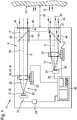
- FIG. 1 Shown schematically is a device according to the invention for optical distance measurement with the most important components for describing their function.
- the device 10 according to the invention has a housing 11 in which a transmitting device 12 for generating a measurement signal 13 and a receiving device 14 for detecting the return of a target object 15 measuring signal 16 are arranged.
- the transmitting device 12 includes a light source 17, which is realized in the embodiment of Figure 1 by a semiconductor laser diode 18.
- the laser diode 18 emits a laser beam 20 in the form of a light beam 22 visible to the human eye.
- the laser diode 18 is operated via a control unit 24, which generates a modulation of the electrical input signal 19 of the diode 18 by a corresponding electronics.
- a control unit 24 which generates a modulation of the electrical input signal 19 of the diode 18 by a corresponding electronics.
- the laser beam 20 then passes through a collimating lens 26 in the form of a lens 28, which in the FIG. 1 is shown in a simplified manner in the form of a single lens 30.
- the objective 28 is optionally located on an adjustment mimic 32, which in principle makes it possible to change the position of the objective in all three spatial directions, for example for adjustment purposes.
- the collimating optics 26 may also already be part of the laser diode 18 or be permanently connected thereto.
- the transmitting branch 12 of the device according to the invention there is also a preferably switchable beam deflection 40, which allows the measuring signal 13, bypassing a target object directly, ie to redirect device internally to the receiving unit 14 of the device 10. In this way, a device-internal reference path 42 is generated, which allows a calibration or a comparison of the measuring system.
- the measuring beam 13 leaves the housing 11 of the device according to the invention through an optical window 44 in the end wall 45 of the device 10.
- the opening of the optical window can be secured, for example, by a shutter 46.
- the actual measurement is the Measuring device 10 then aligned to a target object 15, the distance 48 is to be determined to the meter.
- the signal 16 reflected or also scattered at the desired target object 15 forms a returning beam 49 or 50 which, to a certain extent, returns to the measuring device 10.
- the returning measuring radiation 16 is coupled into the measuring device and in the embodiment of FIG. 1 directed to a receiving optics 52.
- FIG. 1 By way of example, two returning measuring radiation beams 49 and 50 for two different target object distances 48 are shown for clarification.
- the signal returning from the target object 16 falls parallel to the optical axis 51 of the receiving device 14.
- This case is in the embodiment of FIG. 1 represented by the measuring beam 49.
- the returning signal 16 incident in the measuring device is inclined more and more with respect to the axis 51 of the receiving unit 14 due to parallax.
- the beam 50 drawn drawn.
- the receiving optics 52 which in the embodiment of the FIG. 1 also symbolized only schematically by a single lens collimates the returning measurement signal 16 and focuses its beam on the photosensitive surface 66 of a receiving detector 54.
- the detector 54 has for detecting the optical measuring radiation at least one photodiode, such as a PIN diode or an APD (Avalanche Photo Diode) or at least a CCD chip as a photosensitive element 66 on.
- APD Anavalanche Photo Diode
- CCD chip photosensitive element 66
- other surface detectors known in the art as a reception detector are possible.
- the area detector is usually aligned with its active photosensitive surfaces 66 perpendicular to the optical axis of the receiving branch.
- the incident optical signal is converted by the reception detector 54 into an electrical signal 55 and supplied to the further evaluation in an evaluation unit 36 of the device according to the invention.
- the receiving optics 52 which in the embodiment of the FIG. 1 not restrictively also mounted on a Verstellmimik 53 is located approximately at a distance of its focal length from the active surface 66 of the detector, so that incident radiation, which comes from a target object, which is far away from the meter, is focused exactly on the detector or on the active photosensitive surfaces.
- the imaging position for the measuring spot reflected or scattered on the target object is increasingly away from the focus of the receiving lens.
- the returning measuring beam moves with decreasing distance of the target object to the measuring device always further away from the optical axis of the receiving device and thus deviates more and more from the optical axis of the transmitting device.
- the returning measuring beam beam is no longer focused exactly on the detector surface due to the changed imaging conditions on the receiving lens. As the target distance becomes shorter, an increasingly larger spot on the detector surface results.
- the meter of course also has a control and evaluation unit 36.
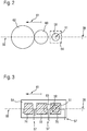
- FIG. 2 a plan view of a detector surface 64 according to the prior art in the direction of the returning from the measurement object measurement signal 16.
- the reference numeral 56 is the common plane of the optical axis 38 of the transmitting unit 12 with the optical axis 51 of the receiving unit 14.
- Der Measurement spot 58 of the returning radiation 16 for very large object distances 48 lies on the optical axis 51 of the receiving unit 14 and is focused on the surface 64 of the detector into a small spot.
- FIG. 2 To illustrate the relationships, a "classic" detector surface 64 of a detector according to the prior art is shown in dashed lines.
- the returning signal 16 falls increasingly obliquely on the receiving objective 52, so that the measuring spot on the detector surface in the direction of arrow 61 in FIG FIG. 2 emigrated.
- FIG. 2 also drawn measuring spot 60 for a small object distance 48 of the target object 15 from the measuring device 10 has thus migrated away from the optical axis 51 of the receiving device and significantly increased in its extent, in particular lateral extent.
- a measuring spot 62 of the returning measurement signal 16 which is again significantly increased and also comes further from the optical axis 51 of the receiving unit 14 to lie.
- Such a displacement of the measuring spot to be detected with the relative distance 48 of a measuring object 15 to the measuring device 10 may possibly lead to the return signal 16 no longer falling on the active surface of the measuring receiver 54 for very small object distances, as indicated by the above , dashed area 64 of a "classic" measuring receiver in FIG. 2 should be indicated.
- the active, photosensitive surface 66 of the detector 54 is designed accordingly and will be described below.
- FIG. 3 shows a first embodiment of the photosensitive surface 66 of a detector of a device according to the invention.
- the detector 54 of the receiving unit 14 in this case has a plurality of photosensitive surfaces 70, 72 and 74, which are separate from each other and form in their entirety the photosensitive surface 66 of the detector.
- the light-sensitive areas of the detector are electrically separated from each other, so that it is possible to switch only one of the photosensitive surfaces 70-74 active, ie, for example, to occupy a voltage signal, so that incident light is converted into an electrical signal.
- the partial surfaces 70, 72 and 74 of the detector can in particular all have the same size, ie area, or else have a different size.
- a connection can be led out of the diode housing, for example, for each surface, so that the respective photosensitive subelement can be activated and selectively used by appropriate contacting or activation of such a terminal.
- This is due to the symbolically represented, electrical connecting lines 57 in the FIGS. 3 to 8 indicated.
- corresponding switching means are provided which make it possible, depending on a corresponding control signal, the respective preferred partial area or Part surfaces of the detector 54 to activate.
- a multiplexer could also be integrated directly into the detector 54, for example into a photodiode.
- the measuring spot 58 comes to lie completely on the photosensitive partial surface 70.
- the photosensitive surface 70 would be actively switched by appropriate circuit means, so that it acts as a detector surface and transferred the optical measurement signal into an electrical measurement signal.
- the likewise present partial surfaces 72 and 74 of the detector are not activated, for example there is no voltage applied to these photosensitive surfaces, so that light which occurs on these surfaces does not contribute to the generation of an electrical signal. If, therefore, extraneous light, which come from other objects that are closer to the meter than the currently measured object 15 in the meter, so this extraneous light would be due to the non-activated, d. H. not turned on photosensitive surfaces 72 and 74 also not detected. This extraneous light would thus also not lead to an increased background noise compared to the measurement signal of the active surface 70 generated by the measuring beam 58.
- the active surface 70 which is activated in particular for very large measuring distances, advantageously has such a lateral extent in the detection plane that it ensures that the measuring spot 58 of the measuring radiation 16 returning from such a far away target object resp. 49 is completely detected.
- a lateral direction is understood to mean a direction perpendicular to the measuring signal direction. Therefore, the dimension of the photosensitive areas 70 should be substantially equal to or slightly larger than the dimensions of a measurement spot 58 for very large object distances. If the measuring spot now moves with decreasing object distance 48 in the direction of the arrow 61 from the original receiving axis 51, then, as in FIG FIG. 2 indicated, the diameter or the lateral dimensions of the measuring spot.
- the lateral direction here is the direction perpendicular to the direction 61, in which the measuring beam emigrates.
- the area detector as a whole has an elongated shape.
- the expansion in the direction of the emigration of the measurement signal is greater, in particular significantly greater, than in orthogonal, i. lateral direction.
- the noise can thus be significantly reduced by extraneous light, since only the part of the area of the detector is used, on which the useful light impinges optimized. Those areas of the detector, which have a relatively high amount of extraneous light, are switched off accordingly.
- only one light-sensitive area of the detector is always active, in particular in this embodiment.
- a plurality of sub-areas may also be activated, in particular when the measurement signal impinges simultaneously on a plurality of subareas and, for example, the sum signal of two subareas is less noisy than the signal of the subareas considered individually. In this case, several partial areas of the detector can be activated according to the invention.
- a short test measurement can be carried out, for example, only for determining the signal components on the individual photosensitive surfaces of the detector of the receiving unit before the actual distance measurement serves. During this test measurement, all or even a plurality of the light-sensitive partial areas of the optical detector can then be briefly activated via the correspondingly provided switching means and, in particular, read out individually.
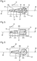
- FIG. 4 1 shows a non-inventive embodiment of a detector 54, in which an envelope 165, which can be drawn around the photosensitive surfaces of the detector, in the direction 61, ie in the direction of emigrating the returning measuring beam for a shorter Meß réelleabstand, rejuvenated.
- the extent of the light-sensitive surfaces 170, 172 or 174 of the detector in the direction perpendicular to the optical axis 51 of the receiving unit 14 is again at least so great that the measuring beam returning from a target object 15 in the near zone at least partially still touches the photosensitive surface 174 falls.
- the light-sensitive area 174 which is used at such distances, may possibly be selected to be significantly lower due to the significantly increased light intensity according to the square law of the square.
- the electrical capacitance of the detector is reduced, so that the temporal response characteristic or, analogously, the frequency response of the measuring system can be significantly increased.
- the envelope 165 which can be drawn around the photosensitive surfaces of the detector in the detector plane, is tapered in the direction 61 of a beam displacement for decreasing target object distances 48. Such an envelope 165 is in FIG. 4 also marked.
- the envelope essentially follows the boundary of the photosensitive subareas, the course of the envelope being interpolated in the direction of the arrow 61, ie, in the direction of a beam shift for decreasing target object distances between two subareas.
- Both the shapes of the photosensitive surfaces and their number within a detector may vary depending on the embodiment. So shows FIG. 5 a detector having a plurality of light-sensitive surfaces 270,272,274 of different sizes formed as rectangles, whose envelope 265 in turn tapers in the direction 61 of a beam shift for decreasing target object distances 48.
- the photosensitive surfaces 270, 272, 274 can, according to the invention, in turn be individually activated during a distance measurement, ie switched on or off.
- FIG. 6 shows a further embodiment with only two separate photosensitive surfaces 370 and 372, however, which are also individually activated according to the principle described above.
- the envelope which can be placed around the photosensitive surfaces of the detector, widens in the direction of shorter object distances.
- Such an embodiment with in the direction 61 expanding envelope, as exemplified in FIG. 7 and FIG. 8 has the advantage that it takes account of the reduced power density of the returning measuring signal for short measuring object distances. Due to a short measuring object distance, the returning measuring beam is no longer optimally focused in the detection plane, since the collimating optics 52 of such a measuring device is usually optimized for very large measuring object distances.
- measuring spot increases rapidly in the detection plane for shorter measuring object distances - compare to the illustration in FIG. 2 - results on the detector surface a reduced power area density or intensity of the measurement signal.
- This effect of the reduced power density of the measuring signal on the detector surface can be counteracted by the fact that the detector surface widens in the direction 61 for shorter object distances or expands again after a previous constriction, as in the exemplary embodiment of a detector according to the invention in FIG FIG. 7 is shown.
- the envelope 465 of the photosensitive detector surfaces 470 and 472 and 474 widens again in the direction 61 for decreasing object distances, after it has first constricted in the region of the transition from the partial element 470 to the partial element 472.
- such a shape should also correspond to the criterion that the light-sensitive surfaces of the detector are shaped and arranged in such a way that an envelope of these surfaces widens in the direction of a beam displacement for decreasing target object distances.
- both the number and / or the shape of the individual light-sensitive surfaces, which may have a corresponding detector, of course, of the in FIG. 7 differ shown, exemplary embodiment.
- the sub-element 472 could also be formed as a rectangle, the other sub-elements 470 and 474 of the photosensitive surface, however, their in FIG. 7 have shown shape.
- FIG. 8 shows a likewise possible embodiment of the idea according to the invention with only two light-sensitive sub-image areas 570 and 572, the envelope 565, however, continuously widens in the direction 61 for shorter object distances.
- the detector according to the invention can be operated with only one or more partial surfaces.
- the device according to the invention is not limited to the embodiments shown in the description.
- the device according to the invention is not limited to the illustrated shapes or numbers of the individual light-sensitive partial areas of the detector.
Landscapes
- Physics & Mathematics (AREA)
- Engineering & Computer Science (AREA)
- General Physics & Mathematics (AREA)
- Radar, Positioning & Navigation (AREA)
- Remote Sensing (AREA)
- Electromagnetism (AREA)
- Computer Networks & Wireless Communication (AREA)
- Measurement Of Optical Distance (AREA)
- Optical Radar Systems And Details Thereof (AREA)
Description
Die Erfindung geht aus von einer Vorrichtung zur optischen Distanzmessung nach dem Oberbegriff des unabhängigen Anspruchs.The invention relates to a device for optical distance measurement according to the preamble of the independent claim.
Optische Entfernungsmessgeräte als solche sind seit längerer Zeit bekannt und werden inzwischen auch kommerziell in hoher Stückzahl vertrieben. Diese Geräte senden einen modulierten Lichtstrahl aus, der auf die Oberfläche eines gewünschten Zielobjektes, dessen Abstand zum Gerät zu ermitteln ist, ausgerichtet wird. Das von dem angepeilten Zielobjekt reflektierte oder gestreute, rücklaufende Licht wird vom Gerät teilweise wieder detektiert und zur Ermittlung des gesuchten Abstandes verwendet.As such, optical distance measuring devices have been known for some time and in the meantime are also sold commercially in large numbers. These devices emit a modulated light beam that is aligned with the surface of a desired target object whose distance from the device is to be determined. The returning light reflected or scattered by the targeted target object is partially re-detected by the device and used to determine the searched distance.
Der Anwendungsbereich derartiger Entfernungsmessgeräte umfasst im Allgemeinen Entfernungen im Bereich von einigen wenigen Zentimetern bis zu mehreren hundert Metern.The scope of such rangefinders generally includes distances in the range of a few centimeters to several hundred meters.
In Abhängigkeit von den zu messenden Laufstrecken und der Rückstrahlfähigkeit des Zielobjektes ergeben sich unterschiedliche Anforderungen an die Lichtquelle, die Qualität des Mess-Strahls sowie an den Detektor.Depending on the distances to be measured and the reflectivity of the target object, different requirements are imposed on the light source, the quality of the measuring beam and on the detector.
Die aus dem Stand der Technik bekannten optischen Entfernungsmessgeräte lassen sich grundsätzlich entsprechend der Anordnung der im Gerät notwendigerweise vorhandenen Sende- bzw. Empfangskanäle in zwei Kategorien einteilen.The known from the prior art optical distance measuring devices can basically be divided into two categories according to the arrangement of necessarily present in the device transmitting or receiving channels.
Zum einen gibt es Vorrichtungen, bei denen der Sendekanal in einem gewissen Abstand zu dem Empfangskanal angeordnet ist, sodass die jeweiligen optischen Achsen parallel zueinander, aber beabstandet voneinander verlaufen. Zum anderen gibt es monoaxiale Messvorrichtungen, bei denen der Empfangskanal koaxial zum Sendekanal verläuft.First, there are devices in which the transmission channel is arranged at a certain distance from the receiving channel, so that the respective optical axes parallel to each other, but spaced from each other. On the other hand, there are monoaxial measuring devices in which the receiving channel runs coaxially to the transmission channel.
Die erstgenannten biaxialen Mess-Systeme haben den Vorteil, dass es einer aufwendigen Strahlungsteilung zur Selektion des rücklaufenden Mess-Signals nicht bedarf, sodass beispielsweise auch ein optisches Übersprechen aus dem Sendekanal direkt in den Empfangskanal besser unterdrückt werden kann.The first-mentioned biaxial measuring systems have the advantage that there is no need for complex radiation division for selecting the returning measuring signal, so that, for example, optical crosstalk from the transmitting channel directly into the receiving channel can be better suppressed.
Andererseits besteht bei biaxialen Entfernungsmessgeräten unter anderem der Nachteil, dass es im Bereich kurzer Messentfernungen aufgrund einer Parallaxe zu Detektionsproblemen kommen kann. Dabei wandert die Abbildung des Zielobjektes auf der Detektoroberfläche des Gerätes, die für große Zielentfernungen noch eindeutig auf dem Detektor liegt, mit kürzer werdender Messentfernung zunehmend von der optischen Achse des Empfangsastes weg und erfährt zudem eine deutliche Änderung des Strahlquerschnittes in der Detektorebene.On the other hand, with biaxial distance measuring devices, there is, inter alia, the disadvantage that detection problems can occur in the region of short measuring distances due to parallax. The image of the target object on the detector surface of the device, which is still clearly located on the detector for large target distances, increasingly moves away from the optical axis of the receiving branch with shorter measuring distance and also undergoes a significant change in the beam cross-section in the detector plane.
Dies bedingt, dass ohne weitere Maßnahmen am Gerät, im Nahbereich der Detektion, d. h. für einen kleinen Abstand zwischen Zielobjekt und Messgerät, das detektierte Mess-Signal gegen Null gehen kann.This requires that without further action on the device, in the vicinity of the detection, d. H. for a small distance between target and measuring device, the detected measuring signal can go to zero.
Derartige Messgeräte können zwar für einen bestimmten Entfernungsbereich optimiert werden, dies bedeutet jedoch dann eine deutliche Einschränkung des dem Messgeräts eigentlich zugänglichen Messbereichs.Although such measuring devices can be optimized for a certain distance range, this then means a clear limitation of the measurement range actually accessible measuring range.
Aus der
Aus der
Aufgabe der vorliegenden Erfindung ist es, ausgehend vom Stand der Technik bei einer Vorrichtung zur optischen Distanzmessung zu gewährleisten, dass über einen möglichst großen Messbereich, ein möglichst konstantes Empfangssignal gemessen werden kann.The object of the present invention is, starting from the state of the art in a device for optical distance measurement, to ensure that a reception signal that is as constant as possible can be measured over the largest possible measuring range.
Diese Aufgabe wird gelöst mit einer erfindungsgemäßen Vorrichtung zur optischen Distanzmessung mit den Merkmalen des unabhängigen Anspruchs.This object is achieved with a device according to the invention for optical distance measurement with the features of the independent claim.
Die erfindungsgemäße Vorrichtung zur optischen Distanzmessung weist eine Sendeeinheit mit einer Lichtquelle zur Aussendung optischer Strahlung, insbesondere modulierter optischer Messstrahlung, und eine zur optischen Achse dieser Sendeeinheit beabstandete Empfangseinheit mit zumindest einem optischen Detektor auf. Der Detektor der Empfangseinheit weist in vorteilhafter Weise eine Mehrzahl von voneinander getrennten, insbesondere voneinander elektrisch getrennten, lichtempfindlichen Flächen auf, die im Betrieb der Vorrichtung getrennt voneinander aktivierbar sind.The device according to the invention for optical distance measurement has a transmitting unit with a light source for emitting optical radiation, in particular modulated optical measuring radiation, and a receiving unit spaced apart from the optical axis of this transmitting unit with at least one optical detector. The detector of the receiving unit advantageously has a plurality of separate, in particular electrically separate, photosensitive surfaces, which can be activated separately from one another during operation of the device.
Erfindungsgemäß erweitert sich die Einhüllende in Richtung der Strahlverschiebung für kleiner werdende Zielobjektabstände, die sich aufgrund einer Parallaxe der rücklaufenden Strahlung ergibt. Dies kann dann insbesondere den Effekt des vergrößerten Messstrahldurchmessers für kleiner werdende Objektabstände kompensieren.According to the invention, the envelope expands in the direction of the beam displacement for decreasing target object distances, which results from a parallax of the returning radiation. This can then compensate in particular for the effect of the enlarged measuring beam diameter for smaller object distances.
Die Einhüllende ist dabei eine hypothetische Kurve, die sich mit minimalem Abstand um den Rand der Lichtempfindlichen Flächen des Detektors legen lässt. Auf diese Weise kann sichergestellt werden, dass für jeden Objektabstand hinreichend Mess-Signal auf die jeweils gerade aktive Teilfläche des Detektors fällt. Insbesondere ist die Form der gesamten optischen Detektionsfläche so gewählt, dass auch im Nahbereich Signal ausreichender Amplitude auf der Detektoroberfläche vorliegt. Dies führt zu einer weiteren Verbesserung des Verhältnisses von Nutzlicht zu Fremdlicht, sodass auch aus diesem Grunde die Messgenauigkeit der Vorrichtung im unmittelbaren Nahbereich erhöht und damit der dem Gerät zugängliche Messbereich erweitert wird.The envelope is a hypothetical curve that can be placed with minimal distance around the edge of the photosensitive surfaces of the detector. In this way it can be ensured that for each object distance sufficient measurement signal falls on the currently active partial area of the detector. In particular, the shape of the entire optical detection surface is selected so that there is sufficient signal amplitude on the detector surface even in the near field. This leads to a further improvement of the ratio from useful light to extraneous light, so that the measuring accuracy of the device is increased in the immediate vicinity and therefore the measuring range accessible to the device is also extended for this reason.
Durch das Anlegen einer Spannung kann die lichtempfindliche Fläche eines optischen Detektors, die typischerweise aus zumindest einem Halbleitermaterial besteht, aktiviert werden. Das heißt, auf die lichtempfindliche Fläche des Detektors auftreffendes Licht wird typischerweise in ein elektrisches Signal verwandelt und kann so über eine nachgeordnete elektronische Schaltung detektiert werden.By applying a voltage, the photosensitive surface of an optical detector, which typically consists of at least one semiconductor material, can be activated. That is, light incident on the photosensitive surface of the detector is typically converted into an electrical signal and can thus be detected via a downstream electronic circuit.
Dazu besitzt die erfindungsgemäße Vorrichtung Schaltmittel, die es ermöglichen, einzelne oder mehrere Teilflächen der lichtempfindlichen Fläche des Detektors an- bzw. Abzuschalten.For this purpose, the device according to the invention has switching means which make it possible to switch on or off individual or several subareas of the photosensitive surface of the detector.
Durch das Abschalten von nicht, oder lediglich teilweise genutzten Fotodiodenflächen kann das Rauschen, welches aufgrund von auf den Detektor auftreffendem Fremdlicht prinzipiell erzeugt wird, deutlich verringert werden, da nur diejenigen lichtempfindlichen Flächen benutzt werden, auf die das für die Messung wesentliche Nutzlicht auftrifft. Insbesondere kann dabei in vorteilhafter weise lediglich auch nur eine einzelne lichtempfindliche Fläche aktiviert werden.By switching off not or only partially used photodiode areas, the noise, which is generated in principle due to impinging on the detector extraneous light can be significantly reduced, since only those photosensitive surfaces are used, which is incident on the useful light for the measurement essential. In particular, only a single photosensitive surface can be activated in an advantageous manner.
Des Weiteren verringert sich aufgrund der kleineren im Betrieb aktiven Fotodiodenfläche auch die elektrische Kapazität der Fotodiode und somit des Detektionssystems. Daher kann die Fotodiode mit einer höheren Frequenz betrieben werden, was wiederum zu einer höheren Messgenauigkeit der erfindungsgemäßen Vorrichtung zur optischen Distanzmessung führt.Furthermore, due to the smaller photodiode area active in operation, the electrical capacitance of the photodiode and thus of the detection system also decreases. Therefore, the photodiode can be operated at a higher frequency, which in turn leads to a higher measurement accuracy of the device according to the invention for optical distance measurement.
Damit ist eine Erweiterung des für dieses Messgerät zugänglichen Messbereichs auf einfache und zuverlässige Weise möglich.This makes it possible to expand the measuring range accessible to this measuring device in a simple and reliable manner.
Vorteilhafte Ausführungsformen und Weiterentwicklungen der erfindungsgemäßen Vorrichtung ergeben sich aus den in den Unteransprüchen aufgeführten Merkmalen.Advantageous embodiments and further developments of the device according to the invention will become apparent from the features listed in the dependent claims.
In vorteilhafter Weise sind jeweils nur diejenige lichtempfindliche Fläche oder diejenigen lichtempfindlichen Flächen der Mehrzahl von lichtempfindlichen Flächen des Detektors aktiv, auf die der größte Anteil der rücklaufenden optischen Mess-Strahlung auftrifft. Dies ermöglicht, dass ein ausreichend starkes Mess-Signal detektiert werden kann, wobei gleichzeitig der Anteil von Fremdlicht, der auf die ungenutzten Bereiche der lichtempfindlichen Fläche des Detektors auftrifft, deutlich reduziert werden kann. Dies ermöglicht ein besseres Signal zu Rauschverhältnis im detektierten Mess-Signal, sodass sowohl die Auflösung des Messgerätes als auch der dem Messgerät zugänglichen Entfernungsbereich deutlich verbessert werden kann.Advantageously, in each case only that photosensitive surface or those photosensitive surfaces of the plurality of photosensitive surfaces of the detector are active, on which the largest proportion of the returning optical measuring radiation impinges. This allows a sufficiently strong measurement signal can be detected, at the same time the proportion of extraneous light on the unused areas of the photosensitive surface the detector hits, can be significantly reduced. This allows a better signal to noise ratio in the detected measurement signal, so that both the resolution of the meter and the range of the meter accessible to the meter can be significantly improved.
Die erfindungsgemäße Vorrichtung weist Mittel auf, die es ermöglichen einzelne lichtempfindliche Flächen des Detektors an- bzw. abzuschalten. Die Aktivierung der jeweiligen lichtempfindlichen Fläche kann beispielsweise dadurch erfolgen, dass für jede Fläche - bei einer gemeinsamen Masse - ein Anschluss nach außen, d. h. beispielsweise aus dem Diodengehäuse geführt wird. Somit kann durch Kontaktierung des entsprechenden Anschlusses beeinflusst werden, welche Fläche aktiviert und somit verwendet werden soll. Alternativerweise ist es möglich, bei mehreren Flächen einen Multiplexer direkt in die Fotodiode zu integrieren.The device according to the invention has means which make it possible to switch on or off individual light-sensitive surfaces of the detector. The activation of the respective photosensitive surface can take place, for example, in that for each surface - with a common mass - a connection to the outside, d. H. for example, out of the diode housing. Thus it can be influenced by contacting the corresponding terminal, which surface should be activated and thus used. Alternatively, it is possible to integrate a multiplexer directly into the photodiode in several areas.
In einer nicht erfindungsgemäßen Ausführungsform verjüngt sich die Einhüllende der lichtempfindlichen Flächen des Detektors in Richtung einer Strahlverschiebung für kleiner werdende Zielobjektabstände, die sich aufgrund einer Parallaxe der rücklaufenden Strahlung ergibt.In an embodiment not according to the invention, the envelope of the light-sensitive surfaces of the detector tapers in the direction of a beam displacement for decreasing target object distances, which results from parallax of the returning radiation.
Die Einhüllende der lichtempfindlichen Flächen des Detektors weist in vorteilhafter Weise eine Symmetrieachse auf, die in der gemeinsamen Ebene der optischen Achsen von Sendeeinheit und Empfangseinheit der Vorrichtung liegt. Dadurch, dass der vom Zielobjekt rücklaufende Mess-Strahl für einen kleiner werdenden Objektabstand lateral in der gemeinsamen Ebene der optischen Achsen von Sendeeinheit und Empfangseinheit auswandert, wird der Detektor in vorteilhafter Weise eine in dieser Richtung elongierte Form haben. Auf diese Weise wird der Abhängigkeit der Richtung des rücklaufenden Mess-Signals von der Entfernung des Messgeräts von einem Zielobjekt Rechung getragen. Vorteilhafterweise wird die Größe der lichtempfindlichen Flächen des Detektors der Empfangseinheit dabei so gewählt, dass noch genügend Signal, beispielsweise auch im Nahbereich, auf die jeweilige aktive Teilfläche des Detektors fällt.The envelope of the photosensitive surfaces of the detector advantageously has an axis of symmetry lying in the common plane of the optical axes of the transmitting unit and receiving unit of the apparatus. Due to the fact that the measuring beam returning from the target object becomes laterally in the common space for a decreasing object distance Level of the optical axes of transmitting unit and receiving unit emigrates, the detector will advantageously have an elongated shape in this direction. In this way the dependence of the direction of the returning measuring signal on the distance of the measuring device from a target object is taken into account. Advantageously, the size of the light-sensitive surfaces of the detector of the receiving unit is chosen so that enough signal, for example, in the vicinity, falls on the respective active partial surface of the detector.
Dies ermöglicht darüber hinaus in vorteilhafter Weise auch der Abhängigkeit der Stärke des rücklaufenden Mess-Signals von der Entfernung des Messgeräts zum Zielobjekt Rechnung zu tragen.This also makes it possible in an advantageous manner to take into account the dependence of the strength of the returning measuring signal from the distance of the measuring device to the target object.
Aufgrund des zugrunde liegenden Abstands-Quadratgesetzes für die Änderung der Intensität mit der zurückgelegten Laufstrecke ist das rücklaufende Mess-Signal für den Nahbereich deutlich größer als für Zielobjekte, die sich weit entfernt von der Messvorrichtung befinden.Due to the underlying distance-squared law for changing the intensity with the distance traveled, the return measurement signal for the near range is significantly larger than for target objects that are far away from the measurement device.
Die Ausdehnung der Einhüllenden aller lichtempfindlichen Flächen des Detektors senkrecht zur gemeinsamen Ebene der optischen Achsen von Sende- und Empfangseinheit kann daher in dem Maße abnehmen, wie das Lichtsignal aufgrund der kürzeren Laufstrecke im Nahbereich zunimmt. Dies hat zudem den Vorteil, dass aufgrund der reduzierten Ausdehnung des Detektors zwar noch genügend Licht aus dem Nahbereich auf den Detektor fällt, dass aber der Detektor aufgrund seiner in dieser Richtung kleiner werdenden aktiven lichtempfindlichen Flächen nicht durch das Licht aus dem Nahbereich übersteuert werden kann.The extension of the envelope of all light-sensitive surfaces of the detector perpendicular to the common plane of the optical axes of the transmitting and receiving unit can therefore decrease as the light signal increases due to the shorter running distance in the near range. This also has the advantage that, due to the reduced extent of the detector, although sufficient light from the near zone falls on the detector, but that the detector can not be overridden by the light from the near range due to its smaller in this direction active photosensitive surfaces.
Dieser Effekt wird nur begrenzt durch den gegenläufigen Effekt, dass aufgrund der schlechteren Fokussierung des rücklaufenden Messstrahlenbündels bei kürzeren Objektabständen, der Durchmesser des Messstrahlenbündels stark zunimmt, und daher die auf eine kleine Detektorfläche auftretende Leistungsdichte des rücklaufenden Messsignals gegebenenfalls zu gering werden könnte. In einem solchen Fall ist ein Detektor vorteilhaft, bei dem sich die Einhüllende der lichtempfindlichen Teilflächen des Detektors in Richtung der Strahlverschiebung für kürzer werdende Objektabstände nicht verjüngt, sondern gerade erweitert.This effect is only limited by the opposite effect that due to the poorer focus of the returning measuring beam at shorter object distances, the diameter of the measuring beam greatly increases, and therefore the power density of the returning measuring signal occurring on a small detector surface may possibly be too low. In such a case, a detector is advantageous in which the envelope of the photosensitive subareas of the detector does not taper in the direction of the beam displacement for shorter object distances, but just expands.
Bei der Größe der Fläche des Detektors bzw. der Größe der einzelnen empfindlichen Teilflächen des Detektors sollte nur sichergestellt sein, dass die wirksame Fläche, d. h. eine aktive Fläche in dem Bereich des Detektors, indem Licht von weit entfernten Zielobjekten auf die Detektoroberfläche auftrifft, groß genug ist, um in diesem Fall möglichst das gesamte Signal zu detektieren, da weit entfernte Messobjekte zu einem relativ schwachen Detektionssignal führen. Dies ist ebenfalls eine Konsequenz aus dem Abstandsquadratgesetz, dem die detektierte Intensität unterliegt.The size of the area of the detector or the size of the individual sensitive subareas of the detector should only ensure that the effective area, ie an active area in the area of the detector, by striking light from far away target objects on the detector surface, becomes large enough is, in this case as far as possible to detect the entire signal, since distant measuring objects to a relatively weak detection signal to lead. This is also a consequence of the law of square law, which is subject to the detected intensity.
Die laterale Ausdehnung der aktiven Flächen des Detektors sollte entsprechend so groß sein, dass noch genügend Licht aus dem unmittelbaren Nahbereich der Detektion auf die jeweils aktive Detektionsfläche gelangt. Aufgrund des hohen Signalpegels, welcher sich wegen der kurzen Wegstrecken im Nahbereich ergibt, ist es in diesem Fall nicht notwendig, die volle Signalstärke zu detektieren.The lateral extent of the active areas of the detector should be correspondingly so large that enough light from the immediate vicinity of the detection reaches the respectively active detection area. Due to the high signal level, which results from the short distances in the near range, it is not necessary in this case to detect the full signal strength.
Ein weiterer Vorteil der beanspruchten Vorrichtung ist der, dass die elektrisch-kapazitiven Eigenschaften des Detektors des Messgerätes aufgrund der erfindungsgemäßen Form der aktiven Detektionsflächen positiv beeinflusst werden. Eine zu große aktive Detektoroberfläche würde die elektrische Kapazität des Detektors erhöhen, sodass die zeitliche Ansprechcharakteristik, bzw. äquivalent dazu der Frequenzgang des Mess-Systems nicht mehr den benötigten Erfordernissen der Zeit- bzw. Frequenzauflösung des Mess-Systems entsprechen würde.Another advantage of the claimed device is that the electrical capacitive properties of the detector of the measuring device are positively influenced due to the inventive form of the active detection surfaces. Too large an active detector surface would increase the electrical capacitance of the detector, so that the time response characteristic, or equivalently the frequency response of the measuring system would no longer meet the required requirements of the time or frequency resolution of the measuring system.
In vorteilhafter Weise lässt sich die erfindungsgemäße Vorrichtung zur optischen Distanzmessung durch die Verwendung eines Lasers, insbesondere einer Laserdiode als Lichtquelle realisieren. Laser und im speziellen Laserdioden sind über den gesamten sichtbaren Spektralbereich der elektromagnetischen Wellen mittlerweile kostengünstig erhältlich. Im Besonderen eignen sich Laserdioden wegen ihrer kompakten Größe und auch verhältnismäßig hohen Ausgangsleistungen für die Verwendung in Vorrichtungen zur optischen Distanzmessung, insbesondere in derartigen, hand gehaltenen Vorrichtungen.Advantageously, the inventive device for optical distance measurement can be realized by the use of a laser, in particular a laser diode as a light source. Lasers and in particular laser diodes are meanwhile available at low cost over the entire visible spectral range of the electromagnetic waves. In particular, laser diodes, because of their compact size and also relatively high output powers, are suitable for use in optical distance measuring devices, especially in such hand-held devices.
Die erfindungsgemäße Vorrichtung zur optischen Distanzmessung ermöglicht somit ein möglichst konstantes Empfangs- bzw. Detektionssignal über einen großen Messbereich von Entfernungen zwischen der Vorrichtung und einem Zielobjekt.The device according to the invention for optical distance measurement thus enables the most constant possible reception or detection signal over a large measuring range of distances between the device and a target object.
Weitere Vorteile der erfindungsgemäßen Vorrichtung sind der nachfolgenden Zeichnung sowie der zughörigen Beschreibung eines Ausführungsbeispiels der erfindungsgemäßen Vorrichtung angegeben.Further advantages of the device according to the invention are given in the following drawing and the appended description of an embodiment of the device according to the invention.
In der Zeichnung sind Ausführungsbeispiele der erfindungsgemäßen Vorrichtung dargestellt.In the drawings, embodiments of the device according to the invention are shown.
Es zeigen:
Figur 1- eine schematisierte Ansicht auf ein Ausführungsbeispiel einer erfindungsgemäßen Vorrichtung zur optischen Distanzmessung,
- Figur 2
- eine schematische Darstellung der Variation des Mess-Strahlenbündels in der Detektionsebene bei Variation des Messobjektabstandes,
- Figur 3
- eine Aufsicht auf die Detektoroberfläche einer erfindungsgemäßen Vorrichtung,
- Figur 4
- eine Aufsicht auf eine nicht erfindungsgemäße Ausführungsform eines Detektors in schematischer Darstellung,
- Figur 5
- eine weitere Ausführungsform für den Detektor einer erfindungsgemäßen Vorrichtung, in schematischer Darstellung,
- Figur 6
- eine weitere Ausführungsform für den Detektor einer erfindungsgemäßen Vorrichtung, in schematischer Darstellung,
- Figur 7
- eine weitere Ausführungsform für den Detektor einer erfindungsgemäßen Vorrichtung, in schematischer Darstellung,
- Figur 8
- eine weitere Ausführungsform für den Detektor einer erfindungsgemäßen Vorrichtung, in schematischer Darstellung,
- FIG. 1
- 1 is a schematic view of an exemplary embodiment of an apparatus according to the invention for optical distance measurement,
- FIG. 2
- a schematic representation of the variation of the measuring beam in the detection plane with variation of the measuring object distance,
- FIG. 3
- a plan view of the detector surface of a device according to the invention,
- FIG. 4
- a plan view of a non-inventive embodiment of a detector in a schematic representation,
- FIG. 5
- a further embodiment for the detector of a device according to the invention, in a schematic representation,
- FIG. 6
- a further embodiment for the detector of a device according to the invention, in a schematic representation,
- FIG. 7
- a further embodiment for the detector of a device according to the invention, in a schematic representation,
- FIG. 8
- a further embodiment for the detector of a device according to the invention, in a schematic representation,
In
Die Sendeeinrichtung 12 beinhaltet eine Lichtquelle 17, die im Ausführungsbeispiel der Figur 1 durch eine Halbleiter-Laserdiode 18 realisiert ist. Die Verwendung anderer Lichtquellen in der erfindungsgemäßen Vorrichtung ist aber ebenso möglich. Die Laserdiode 18 sendet einen Laserstrahl 20 in Form eines für das menschliche Auge sichtbaren Lichtbündels 22 aus.The transmitting
Die Laserdiode 18 wird dazu über ein Steuergerät 24 betrieben, das durch eine entsprechende Elektronik eine Modulation des elektrischen Eingangssignals 19 der Diode 18 erzeugt. Durch eine derartige Modulation des Diodenstroms lässt sich erreichen, dass das optische Mess-Signal 13, welches zur Entfernungsmessung genutzt wird, ebenfalls in gewünschter Weise moduliert wird.The laser diode 18 is operated via a
Das Laserstrahlbündel 20 durchläuft anschließend eine Kollimationsoptik 26 in Form eines Objektivs 28, das in der
Alternativ kann die Kollimationsoptik 26 jedoch auch bereits Bestandteil der Laserdiode 18 sein bzw. fest mit dieser verbunden sein.Alternatively, however, the collimating optics 26 may also already be part of the laser diode 18 or be permanently connected thereto.
Nach Durchlaufen des Objektivs 28 ergibt ein beispielsweise amplitudenmoduliertes Signal 13 in Form eines parallelen Lichtbündels 37, das sich entlang der optischen Achse 38 der Sendeeinheit 12 ausbreitet, wie es in
Wird mit der erfindungsgemäßen Vorrichtung eine Distanzmessung durchgeführt, verlässt der Mess-Strahl 13 das Gehäuse 11 der erfindungsgemäßen Vorrichtung durch ein optisches Fenster 44 in der Stirnwand 45 des Gerätes 10. Die Öffnung des optischen Fensters kann beispielsweise durch einen Shutter 46 gesichert sein. Zur eigentlichen Messung wird das Messgerät 10 sodann auf ein Zielobjekt 15 ausgerichtet, dessen Entfernung 48 zum Messgerät ermittelt werden soll. Das an dem gewünschten Zielobjekt 15 reflektierte oder auch gestreute Signal 16 bildet ein rücklaufendes Strahlenbündel 49 bzw. 50, das zu einem gewissen Teil wieder in das Messgerät 10 zurückgelangt.If a distance measurement is carried out with the device according to the invention, the measuring
Durch ein Eintrittsfenster 47 an der Stirnseite 45 des Geräts 10 wird die rücklaufende Mess-Strahlung 16 in das Messgerät eingekoppelt und im Ausführungsbeispiel der
In
Die Empfangsoptik 52, die im Ausführungsbeispiel der
Die Empfangsoptik 52, die im Ausführungsbeispiel der
Auf weitere, im Messgerät vorhandene Komponenten, die aber für das Verständnis der erfindungsgemäßen Vorrichtung nicht unbedingt notwendig sind, soll in diesem Zusammenhang nicht weiter eingegangen werden. Es sei nur angemerkt, dass das Messgerät natürlich auch über einen Steuer- und Auswerteeinheit 36 verfügt.On further, existing in the meter components, but for the understanding of the device according to the invention are not absolutely necessary, will not be discussed further in this context. It should only be noted that the meter of course also has a control and
Die Zusammenhänge zwischen dem Abstand des Zielobjektes vom Messgerät und der Position bzw. der Größe des Messflecks auf der Detektoroberfläche ist in schematischer Weise in
Mit abnehmender Distanz 48 des Messgerätes 10 von einem Zielobjekt 15 fällt das rücklaufende Signal 16 zunehmend schräger auf das Empfangsobjektiv 52 ein, sodass auch der Messfleck auf der Detektoroberfläche in Richtung des Pfeils 61 in
Der in
Bei sehr kleinem Messabstand 48 des Messobjektes 15 zum Messgerät ergibt sich in der Detektorebene ein Messfleck 62 des rücklaufenden Mess-Signals 16, der nochmals deutlich vergrößert ist und zudem auch weiter entfernt von der optischen Achse 51 der Empfangseinheit 14 zu liegen kommt. Eine solche Verschiebung des zu detektierenden Messflecks mit dem relativen Abstand 48 eines Messobjektes 15 zum Messgerät 10 kann ggf. dazu führen, dass für sehr kleine Objektabstände, das rücklaufende Signal 16 nicht mehr auf die aktive Fläche des Messempfängers 54 fällt, wie dies durch die angedeutete, gestrichelt eingezeichnete Fläche 64 eines "klassischen" Messempfängers in
Um die Variation in der Größe und Lage des Messflecks in der Detektionsebene der Empfangseinheit 14 Rechnung zu tragen, ist die aktive, lichtempfindliche Oberfläche 66 des erfindungsgemäßen Detektors 54 entsprechend gestaltet und soll nachfolgend beschrieben werden.In order to take into account the variation in the size and position of the measuring spot in the detection plane of the receiving
Zu Aktivierung einer lichtempfindlichen Teilfläche des Detektors kann beispielsweise für jede Fläche ein Anschluss aus dem Diodengehäuse herausgeführt werden, sodass durch entsprechende Kontaktierung bzw. Ansteuerung eines solchen Anschlusses das jeweilige lichtempfindliche Teilelement angesteuert und selektiv verwendet werden kann. Dies sei durch die symbolisch dargestellten, elektrischen Verbindungsleitungen 57 in den
Für sehr große Objektabstände 48 zwischen dem Zielobjekt 15 und dem Messgerät 10 kommt der Messfleck 58 vollständig auf der lichtempfindlichen Teilfläche 70 zu liegen. In diesem Fall, d. h. für große Messdistanzen würde durch entsprechende Schaltungsmittel, lediglich die lichtempfindliche Fläche 70 aktiv geschaltet, sodass diese als Detektorfläche wirkt und das optische Mess-Signal in ein elektrisches Mess-Signal überführt. Die ebenfalls vorhandenen Teilflächen 72 und 74 des Detektors sind dabei nicht aktiviert, es liegt beispielsweise keine Spannung an diesen lichtempfindlichen Oberflächen an, sodass Licht, welches auf diese Oberflächen auftritt, nicht zu der Erzeugung eines elektrischen Signals beiträgt. Sollte also Fremdlicht, welches von anderen Objekten, die näher am Messgerät liegen als das gegenwärtig zu vermessende Objekt 15 in das Messgerät gelangen, so würde dieses Fremdlicht jedoch aufgrund der nicht aktivierten, d. h. nicht eingeschalteten lichtempfindlichen Flächen 72 und 74 auch nicht detektiert. Dieses Fremdlicht würde somit auch nicht zu einem erhöhten Untergrundrauschen gegenüber dem von dem Messbündel 58 erzeugten Mess-Signal der aktiven Fläche 70 führen.For very large object distances 48 between the
Die aktive Fläche 70, welche insbesondere für sehr große Messentfernungen aktiviert ist, weist in vorteilhafter Weise eine derartige laterale Ausdehnung in der Detektionsebene auf, dass diese sicherstellt, dass der Messfleck 58 der von einem solchen, weit entfernten Zielobjekt rücklaufenden Mess-Strahlung 16 bzw. 49 vollständig detektiert wird. Als laterale Richtung sei hierbei eine Richtung senkrecht zur Messsignalrichtung verstanden. Daher sollte die Abmessung der lichtempfindlichen Flächen 70 im Wesentlichen gleich bzw. leicht größer als die Abmessungen eines Messflecks 58 für sehr große Objektabstände sein. Wandert nun der Messfleck mit abnehmendem Objektabstand 48 in Richtung des Pfeils 61 von der ursprüngliche Empfangsachse 51 aus, so vergrößert sich, wie in
In Richtung 61 einer Strahlverschiebung für kleiner werdende Zielobjektabstände 48 besitzt der Flächendetektor insgesamt eine elongierte Form. Dabei ist die Ausdehnung in Richtung der Auswanderung des Messsignals größer, insbesondere deutlich größer, als in dazu orthogonaler, d.h. lateraler Richtung.In the
Bei dem Auswandern des rücklaufenden Mess-Strahlbündels kommt es zu einer Situation, bei der das Mess-Strahlbündel beispielsweise Teile beider lichtempfindlichen Flächen 70 bzw. 72 zumindest teilweise überstreicht, wie dies mittels des gestrichelt eingezeichneten Messfleckes 63 in
Zur Bestimmung derjenigen Fläche oder Teilflächen, welche den höchsten Nutzlichtanteil und somit auch das höchsten "Signal zu Rauschverhältnis" aufweist, kann beispielsweise vor der eigentlichen Entfernungsmessung eine kurze Testmessung durchgeführt werden, welche lediglich zur Ermittlung der Signalanteile auf den einzelnen lichtempfindlichen Flächen des Detektors der Empfangseinheit dient. Während dieser Testmessung können dann über die entsprechend vorgesehenen Schaltmittel kurzzeitig alle oder auch eine Mehrzahl der lichtempfindlichen Teilflächen des optischen Detektors aktiviert werden und insbesondere einzeln ausgelesen werden. Auf diese Weise kann festgestellt werden, auf welche lichtempfindliche Teilfläche das stärkste Lichtsignal auffällt, um zu entscheiden, ob lediglich eine einzelne Fläche zu aktivieren ist, oder ob mehrere Flächen, die eine echte Teilmenge aller verfügbaren lichtempfindlichen Flächen darstellen, ein besseres Messsignal, insbesondere ein besseres Signal-zu-Rausch-Verhältnis ergeben.In order to determine that surface or partial surfaces which has the highest useful light component and thus also the highest "signal-to-noise ratio", a short test measurement can be carried out, for example, only for determining the signal components on the individual photosensitive surfaces of the detector of the receiving unit before the actual distance measurement serves. During this test measurement, all or even a plurality of the light-sensitive partial areas of the optical detector can then be briefly activated via the correspondingly provided switching means and, in particular, read out individually. In this way, it can be ascertained which photosensitive subarea strikes the strongest light signal in order to decide whether only a single area is to be activated or whether several areas which represent a true subset of all available photosensitive areas provide a better measuring signal, in particular result in a better signal-to-noise ratio.
Bei sehr kleinem Messabstand 48 eines Messobjekt 15 zum Messgerät 10, bei welchem der Messfleck weiter in Richtung des Pfeils 61 in
Die Ausdehnung der lichtempfindlichen Flächen 170, 172 bzw. 174 des Detektors in Richtung senkrecht zur optischen Achse 51 der Empfangseinheit 14 ist dabei wiederum zumindest so groß, dass der von einem Zielobjekt 15 im Nahbereich rücklaufende Mess-Strahl zumindest teilweise noch auf die lichtempfindliche Fläche 174 fällt. Dies bedeutet insbesondere, dass für den Fall kurzer Entfernungen 48 zu einem Zielobjekt 15 aufgrund der gemäß des Abstandsquadratgesetzes deutlich erhöhten Lichtintensität, die lichtempfindliche Fläche 174, die bei derartigen Entfernungen zur Verwendung kommt, gegebenenfalls deutlich geringer ausgewählt sein kann. Dies führt dazu, dass sich die elektrische Kapazität des Detektors verringert, sodass auch die zeitliche Ansprechcharakteristik bzw. analog der Frequenzgang des Mess-Systems deutlich erhöht werden kann.The extent of the light-
Die Einhüllende 165, welche sich um die lichtempfindliche Flächen des Detektors in der Detektorebene legen bzw. zeichnen lässt, ist in Richtung 61 einer Strahlverschiebung für kleiner werdende Zielobjektabstände 48, verjüngt. Eine derartige Einhüllende 165 ist in
Sowohl die Formen der lichtempfindlichen Flächen als auch deren Anzahl innerhalb eines Detektors können je nach Ausführungsform variieren. So zeigt
Bei den konkreten Ausgestaltungen einer erfindungsgemäßen Vorrichtung kann sowohl die Anzahl und/oder die Form der einzelnen lichtempfindlichen Flächen, die ein entsprechender Detektor aufweisen kann, selbstverständlich von der in
Es gilt - je nach konstruktiver Ausgestaltung der Messvorrichtung - den Effekt des Abstandsquadratgesetztes einerseits, sowie den Effekt der mehr oder weniger schlechten Fokussierung anderseits, die sich beide bei kürzer werdenden Messobjektabständen einstellen, jedoch für die Stärke des Messsignals eine gegenläufige Auswirkung haben, gegeneinander abzuwägen und die optimierte Form für die lichtempfindlichen Flächen, insbesondere für die Einhüllende der lichtempfindlichen Flächen zu finden.It is true - depending on the structural design of the measuring device - the effect of the square equations on the one hand, and the effect of more or less poor focus on the other hand, both set at shorter Meßobjektabständen, but for the strength of the measurement signal have an opposite effect, weigh against each other and to find the optimized form for the photosensitive surfaces, in particular for the envelope of the photosensitive surfaces.
Unabhängig von der Form der Einhüllenden der lichtempfindlichen Flächen sind dieses jedoch jeweils einzeln aktivierbar, so dass der erfindungsgemäße Detektor mit lediglich einer oder auch mehreren Teilflächen betrieben werden kann.Regardless of the shape of the envelope of the photosensitive surfaces, however, they can each be activated individually, so that the detector according to the invention can be operated with only one or more partial surfaces.
Die erfindungsgemäße Vorrichtung ist nicht auf die in der Beschreibung dargestellten Ausführungsformen beschränkt.The device according to the invention is not limited to the embodiments shown in the description.
Insbesondere ist die erfindungsgemäße Vorrichtung nicht beschränkt auf die dargestellten Formen bzw. Anzahlen der einzelnen lichtempfindlichen Teilflächen des Detektors.In particular, the device according to the invention is not limited to the illustrated shapes or numbers of the individual light-sensitive partial areas of the detector.
Claims (11)
- Device for optically measuring distance, in particular a handheld device, having a transmitting unit (12) with a light source (17, 18) for emitting optical measurement radiation (13, 20, 22) toward a target object (15), and having a receiving unit (14), which is located at a distance from the optical axis (38) of the transmitting unit (12) and has at least one optical detector (54) for receiving optical radiation (16, 49, 50) returning from the target object (15), wherein the detector (54) of the receiving unit (14) has a plurality of mutually separate light-sensitive surfaces (70, 72, 74; 170, 172, 174; 270, 272, 274; 370, 372; 470, 472; 570, 572) which are able to be activated separately from one another, characterized in that the light-sensitive surfaces (470, 472, 474; 570, 572) of the detector (54) are formed and/or arranged such that an envelope (465, 565) of these surfaces (470, 472, 474; 570, 572) expands in the direction (61) of a beam displacement for progressively diminishing target object distances (48).
- Device according to Claim 1, characterized in that means (55) are provided that permit individual light-sensitive surfaces (70, 72, 74; 170, 172, 174; 270, 272, 274; 370, 372; 470, 472; 570, 572) of the detector (54) to be switched on or off.
- Device according to Claim 1 or 2, characterized in that the light-sensitive surfaces (70, 72, 74; 170, 172, 174; 270, 272, 274; 370, 372; 470, 472; 570, 572) of the detector (54) are formed and/or arranged such that an envelope (165, 265, 365, 465, 565) of these surfaces (70, 72, 74; 170, 172, 174; 270, 272, 274; 370, 372; 470, 472; 570, 572) has a greater extent in the direction (61) of a beam displacement for progressively diminishing target object distances (48) than in the direction that is orthogonal with respect thereto.
- Device according to one of the preceding claims, characterized in that the envelope (165, 265, 365, 465, 565) of the light-sensitive surfaces (70, 72, 74; 170, 172, 174; 270, 272, 274; 370, 372; 470, 472; 570, 572) of the detector (54) has an axis of symmetry that is located in the common plane (56) of the optical axes of transmitting unit (38) and receiving unit (51).
- Device according to one of the preceding claims, characterized in that the extent of the light-sensitive surfaces (70, 72, 74; 170, 172, 174; 270, 272, 274; 370, 372; 470, 472; 570, 572) of the detector (54) is at least large enough for the measurement spot (58) of the returning radiation (16, 49) from a target object (15) with a large object distance to be completely detected.
- Device according to one of the preceding claims, characterized in that the extent of the light-sensitive surfaces (70, 72, 74; 170, 172, 174; 270, 272, 274; 370, 372; 470, 472; 570, 572) of the detector (54) in a direction perpendicular to the optical axis (51) of the receiving unit (14) is at least large enough for the measurement beam (50) returning from a target object (15) in the near region to at least partially still be incident on the light-sensitive surface (70, 72, 74; 170, 172, 174; 270, 272, 274; 370, 372; 470, 472; 570, 572).
- Device according to one of the preceding claims, characterized in that the light source (17, 18) is a laser, in particular a laser diode (18).
- Device according to Claim 7, characterized in that the light source (17, 18) emits radiation in the wavelength range of the spectrum of electromagnetic waves that is visible to the human eye.
- Method for operating a device according to at least one of Claims 1 to 8, characterized in that a detector (54) of a receiving unit (14) that is provided in the device has a multiplicity (m) of mutually separate light-sensitive surfaces (70, 72, 74; 170, 172, 174; 270, 272, 274; 370, 372; 470, 472; 570, 572), from which only in each case a subset (n, where n<m) of the provided light-sensitive surfaces (70, 72, 74; 170, 172, 174; 270, 272, 274; 370, 372; 470, 472; 570, 572) is activated during a distance measurement.
- Method for operating a device for optically measuring distance according to Claim 9, characterized in that in each case only one light-sensitive surface (n=1) (70, 72, 74; 170, 172, 174; 270, 272, 274; 370, 372; 470, 472; 570, 572) of the detector (54) is active during a distance measurement.
- Method according to Claim 10, characterized in that in each case only the light-sensitive surface (70, 72, 74; 170, 172, 174; 270, 272, 274; 370, 372; 470, 472; 570, 572) of the detector (54) of the device onto which the largest proportion of the optical radiation (16, 49, 50) returning from a target object (15) is incident is active during a distance measurement.
Applications Claiming Priority (2)
| Application Number | Priority Date | Filing Date | Title |
|---|---|---|---|
| DE102006013290A DE102006013290A1 (en) | 2006-03-23 | 2006-03-23 | Device for optical distance measurement and method for operating such a device |
| PCT/EP2007/051193 WO2007107408A1 (en) | 2006-03-23 | 2007-02-08 | Device for optically measuring distance and method for operating said type of device |
Publications (2)
| Publication Number | Publication Date |
|---|---|
| EP2002208A1 EP2002208A1 (en) | 2008-12-17 |
| EP2002208B1 true EP2002208B1 (en) | 2017-09-06 |
Family
ID=37964995
Family Applications (1)
| Application Number | Title | Priority Date | Filing Date |
|---|---|---|---|
| EP07704446.9A Not-in-force EP2002208B1 (en) | 2006-03-23 | 2007-02-08 | Device for optically measuring distance and method for operating said type of device |
Country Status (5)
| Country | Link |
|---|---|
| US (1) | US7760335B2 (en) |
| EP (1) | EP2002208B1 (en) |
| CN (1) | CN101405565B (en) |
| DE (1) | DE102006013290A1 (en) |
| WO (1) | WO2007107408A1 (en) |
Families Citing this family (77)
| Publication number | Priority date | Publication date | Assignee | Title |
|---|---|---|---|---|
| DE102007053852A1 (en) * | 2007-11-12 | 2009-05-14 | Robert Bosch Gmbh | Device for optical distance measurement |
| US9482755B2 (en) | 2008-11-17 | 2016-11-01 | Faro Technologies, Inc. | Measurement system having air temperature compensation between a target and a laser tracker |
| KR101734354B1 (en) | 2009-04-29 | 2017-05-11 | 코닌클리케 필립스 엔.브이. | A laser diode based multiple-beam laser spot imaging system for characterization of vehicle dynamics |
| US8659749B2 (en) * | 2009-08-07 | 2014-02-25 | Faro Technologies, Inc. | Absolute distance meter with optical switch |
| DE102009029372A1 (en) | 2009-09-11 | 2011-03-24 | Robert Bosch Gmbh | Measuring device for measuring a distance between the measuring device and a target object by means of optical measuring radiation |
| DE102009029364A1 (en) * | 2009-09-11 | 2011-03-24 | Robert Bosch Gmbh | Measuring device for measuring a distance between the measuring device and a target object by means of optical measuring radiation |
| US9400170B2 (en) | 2010-04-21 | 2016-07-26 | Faro Technologies, Inc. | Automatic measurement of dimensional data within an acceptance region by a laser tracker |
| US9772394B2 (en) | 2010-04-21 | 2017-09-26 | Faro Technologies, Inc. | Method and apparatus for following an operator and locking onto a retroreflector with a laser tracker |
| US9377885B2 (en) | 2010-04-21 | 2016-06-28 | Faro Technologies, Inc. | Method and apparatus for locking onto a retroreflector with a laser tracker |
| US8619265B2 (en) | 2011-03-14 | 2013-12-31 | Faro Technologies, Inc. | Automatic measurement of dimensional data with a laser tracker |
| TWI448666B (en) * | 2010-06-15 | 2014-08-11 | Pixart Imaging Inc | Calibrating method of calibrating measured distance of measured object measured by distance-measuring device according to ambient temperature and device thereof |
| US8902408B2 (en) | 2011-02-14 | 2014-12-02 | Faro Technologies Inc. | Laser tracker used with six degree-of-freedom probe having separable spherical retroreflector |
| US9001029B2 (en) * | 2011-02-15 | 2015-04-07 | Basf Se | Detector for optically detecting at least one object |
| DE112012001082B4 (en) | 2011-03-03 | 2015-12-03 | Faro Technologies Inc. | Method for measuring goals |
| DE102011005740A1 (en) * | 2011-03-17 | 2012-09-20 | Robert Bosch Gmbh | Measuring device for measuring a distance between the measuring device and a target object by means of optical measuring radiation |
| US9482529B2 (en) | 2011-04-15 | 2016-11-01 | Faro Technologies, Inc. | Three-dimensional coordinate scanner and method of operation |
| US9686532B2 (en) | 2011-04-15 | 2017-06-20 | Faro Technologies, Inc. | System and method of acquiring three-dimensional coordinates using multiple coordinate measurement devices |
| USD688577S1 (en) | 2012-02-21 | 2013-08-27 | Faro Technologies, Inc. | Laser tracker |
| CN103649673A (en) | 2011-04-15 | 2014-03-19 | 法罗技术股份有限公司 | Enhanced position detector in laser tracker |
| US9164173B2 (en) | 2011-04-15 | 2015-10-20 | Faro Technologies, Inc. | Laser tracker that uses a fiber-optic coupler and an achromatic launch to align and collimate two wavelengths of light |
| DE102011107645A1 (en) * | 2011-07-12 | 2013-01-17 | Leica Microsystems Cms Gmbh | Apparatus and method for detecting light |
| US9638507B2 (en) | 2012-01-27 | 2017-05-02 | Faro Technologies, Inc. | Measurement machine utilizing a barcode to identify an inspection plan for an object |
| EP2708914A1 (en) * | 2012-09-18 | 2014-03-19 | Sick Ag | Optoelectronic sensor and method for recording a depth map |
| EP2936052B1 (en) | 2012-12-19 | 2021-04-28 | Basf Se | Detector for optically detecting at least one object |
| US9041914B2 (en) | 2013-03-15 | 2015-05-26 | Faro Technologies, Inc. | Three-dimensional coordinate scanner and method of operation |
| JP6440696B2 (en) | 2013-06-13 | 2018-12-19 | ビーエーエスエフ ソシエタス・ヨーロピアBasf Se | Detector for optically detecting the orientation of at least one object |
| JP2016529473A (en) | 2013-06-13 | 2016-09-23 | ビーエーエスエフ ソシエタス・ヨーロピアBasf Se | Detector for optically detecting at least one object |
| CN105637320B (en) | 2013-08-19 | 2018-12-14 | 巴斯夫欧洲公司 | optical detector |
| JP6483127B2 (en) | 2013-08-19 | 2019-03-13 | ビーエーエスエフ ソシエタス・ヨーロピアBasf Se | Detector for determining the position of at least one object |
| DE102014207599B4 (en) * | 2014-04-23 | 2024-09-26 | Robert Bosch Gmbh | Method and computer program for operating a photodetector |
| US9395174B2 (en) | 2014-06-27 | 2016-07-19 | Faro Technologies, Inc. | Determining retroreflector orientation by optimizing spatial fit |
| JP6660931B2 (en) | 2014-07-08 | 2020-03-11 | ビーエーエスエフ ソシエタス・ヨーロピアBasf Se | Detector for determining the position of at least one object |
| EP2998700B2 (en) * | 2014-09-18 | 2022-12-21 | Hexagon Technology Center GmbH | Electro-optical distance gauge and distance measuring method |
| JP6578006B2 (en) | 2014-09-29 | 2019-09-18 | ビーエーエスエフ ソシエタス・ヨーロピアBasf Se | Detector for optically determining the position of at least one object |
| EP3230841B1 (en) | 2014-12-09 | 2019-07-03 | Basf Se | Optical detector |
| CN107438775B (en) | 2015-01-30 | 2022-01-21 | 特里纳米克斯股份有限公司 | Detector for optical detection of at least one object |
| JP2016170114A (en) | 2015-03-13 | 2016-09-23 | 株式会社東芝 | Distance measuring device and photodetector |
| US10955936B2 (en) | 2015-07-17 | 2021-03-23 | Trinamix Gmbh | Detector for optically detecting at least one object |
| US10620300B2 (en) | 2015-08-20 | 2020-04-14 | Apple Inc. | SPAD array with gated histogram construction |
| EP3350988B1 (en) | 2015-09-14 | 2019-08-07 | trinamiX GmbH | 3d camera |
| WO2018019921A1 (en) | 2016-07-29 | 2018-02-01 | Trinamix Gmbh | Optical sensor and detector for optical detection |
| US10502830B2 (en) | 2016-10-13 | 2019-12-10 | Waymo Llc | Limitation of noise on light detectors using an aperture |
| EP3532864B1 (en) | 2016-10-25 | 2024-08-28 | trinamiX GmbH | Detector for an optical detection of at least one object |
| WO2018077870A1 (en) | 2016-10-25 | 2018-05-03 | Trinamix Gmbh | Nfrared optical detector with integrated filter |
| US11860292B2 (en) | 2016-11-17 | 2024-01-02 | Trinamix Gmbh | Detector and methods for authenticating at least one object |
| KR102502094B1 (en) | 2016-11-17 | 2023-02-21 | 트리나미엑스 게엠베하 | Detector for optically detecting at least one object |
| CN106871940B (en) * | 2016-12-26 | 2019-06-21 | 杭州科聪自动化有限公司 | Sensor, intelligent robot, automatic production line, industrial robot |
| DE102017101945B4 (en) * | 2017-02-01 | 2026-02-12 | OSRAM Opto Semiconductors Gesellschaft mit beschränkter Haftung | Measurement setup with an optical transmitter and an optical receiver |
| DE102017106380B4 (en) * | 2017-03-24 | 2021-10-07 | Sick Ag | Optoelectronic sensor and method for detecting objects |
| EP3392676B1 (en) * | 2017-04-18 | 2020-07-01 | Espros Photonics AG | Optoelectronic sensor device and method for controlling the same |
| KR102623150B1 (en) | 2017-04-20 | 2024-01-11 | 트리나미엑스 게엠베하 | light detector |
| EP3639057B1 (en) * | 2017-05-11 | 2021-11-03 | Huawei Technologies Co., Ltd. | Time-of-flight apparatus |
| CN110998223B (en) | 2017-06-26 | 2021-10-29 | 特里纳米克斯股份有限公司 | a detector for determining the position of at least one object |
| EP3646057A1 (en) | 2017-06-29 | 2020-05-06 | Apple Inc. | Time-of-flight depth mapping with parallax compensation |
| EP3428574A1 (en) | 2017-07-11 | 2019-01-16 | Fondazione Bruno Kessler | Device for measuring a distance and method for measuring said distance |
| EP3438699A1 (en) * | 2017-07-31 | 2019-02-06 | Hexagon Technology Center GmbH | Range finder using spad arrangement for acquiring multiple targets |
| US10955552B2 (en) | 2017-09-27 | 2021-03-23 | Apple Inc. | Waveform design for a LiDAR system with closely-spaced pulses |
| DE102017222974A1 (en) | 2017-12-15 | 2019-06-19 | Ibeo Automotive Systems GmbH | Arrangement and method for determining a distance of at least one object with light signals |
| DE102017222972A1 (en) | 2017-12-15 | 2019-07-04 | Ibeo Automotive Systems GmbH | Receiving arrangement for receiving light signals |
| DE102017222969A1 (en) * | 2017-12-15 | 2019-06-19 | Ibeo Automotive Systems GmbH | Method for improved near and far detection of a LIDAR receiving unit |
| KR102403544B1 (en) | 2017-12-18 | 2022-05-30 | 애플 인크. | Time-of-flight sensing using an addressable array of emitters |
| JP7013925B2 (en) * | 2018-02-23 | 2022-02-01 | 株式会社デンソー | Optical ranging device and its method |
| DE102018205378A1 (en) | 2018-04-10 | 2019-10-10 | Ibeo Automotive Systems GmbH | Method for controlling sensor elements of a LIDAR measuring system |
| DE102018109544A1 (en) | 2018-04-20 | 2019-10-24 | Sick Ag | Optoelectronic sensor and method for distance determination |
| CN109283510B (en) * | 2018-08-17 | 2021-08-31 | 南京矽力微电子技术有限公司 | Light sensing devices and electronic equipment |
| EP3620822B1 (en) * | 2018-09-06 | 2025-10-29 | STMicroelectronics (Research & Development) Limited | Non-contiguous layouts for photosensitive apparatus |
| US11561284B2 (en) * | 2018-11-02 | 2023-01-24 | Waymo Llc | Parallax compensating spatial filters |
| US12117286B2 (en) | 2019-02-11 | 2024-10-15 | Apple Inc. | Depth sensing using a sparse array of pulsed beams |
| US11500094B2 (en) | 2019-06-10 | 2022-11-15 | Apple Inc. | Selection of pulse repetition intervals for sensing time of flight |
| US11555900B1 (en) | 2019-07-17 | 2023-01-17 | Apple Inc. | LiDAR system with enhanced area coverage |
| US11733359B2 (en) * | 2019-12-03 | 2023-08-22 | Apple Inc. | Configurable array of single-photon detectors |
| JP2020042049A (en) * | 2019-12-12 | 2020-03-19 | 株式会社東芝 | Distance measuring device and photodetector |
| CN111352095B (en) * | 2020-04-17 | 2024-12-31 | 深圳市镭神智能系统有限公司 | Laser radar receiving system and laser radar |
| US12442926B2 (en) | 2021-02-04 | 2025-10-14 | Apple Inc. | Time-of-flight depth sensing with improved linearity |
| US12196860B2 (en) | 2021-03-02 | 2025-01-14 | Apple Inc. | Depth sensor calibration using internal reflections |
| US11681028B2 (en) | 2021-07-18 | 2023-06-20 | Apple Inc. | Close-range measurement of time of flight using parallax shift |
| US12517230B2 (en) * | 2022-04-13 | 2026-01-06 | Allegro Microsystems, Llc | Photosensor having range parallax compensation |
Citations (1)
| Publication number | Priority date | Publication date | Assignee | Title |
|---|---|---|---|---|
| US6301003B1 (en) * | 1998-08-05 | 2001-10-09 | Denso Corporation | Optical distance measuring apparatus selectively activating a matrix of light sensitive cells |
Family Cites Families (6)
| Publication number | Priority date | Publication date | Assignee | Title |
|---|---|---|---|---|
| JP3609559B2 (en) * | 1996-10-17 | 2005-01-12 | 松下電器産業株式会社 | Position detecting element and distance sensor |
| DE10051302C5 (en) * | 2000-10-13 | 2007-12-27 | Jenoptik Ag | Laser distance measuring device for the near and far range with special receiver |
| DE10130763A1 (en) * | 2001-06-26 | 2003-01-02 | Bosch Gmbh Robert | Device for optical distance measurement over a large measuring range |
| JP2003149338A (en) * | 2001-11-09 | 2003-05-21 | Denso Corp | Object recognition device and distance measuring device |
| JP2005265606A (en) * | 2004-03-18 | 2005-09-29 | Fuji Electric Device Technology Co Ltd | Distance measuring device |
| US7532311B2 (en) * | 2005-04-06 | 2009-05-12 | Lockheed Martin Coherent Technologies, Inc. | Efficient lidar with flexible target interrogation pattern |
-
2006
- 2006-03-23 DE DE102006013290A patent/DE102006013290A1/en not_active Withdrawn
-
2007
- 2007-02-08 WO PCT/EP2007/051193 patent/WO2007107408A1/en not_active Ceased
- 2007-02-08 EP EP07704446.9A patent/EP2002208B1/en not_active Not-in-force
- 2007-02-08 CN CN2007800099693A patent/CN101405565B/en not_active Expired - Fee Related
- 2007-02-08 US US12/162,836 patent/US7760335B2/en active Active
Patent Citations (1)
| Publication number | Priority date | Publication date | Assignee | Title |
|---|---|---|---|---|
| US6301003B1 (en) * | 1998-08-05 | 2001-10-09 | Denso Corporation | Optical distance measuring apparatus selectively activating a matrix of light sensitive cells |
Also Published As
| Publication number | Publication date |
|---|---|
| US7760335B2 (en) | 2010-07-20 |
| DE102006013290A1 (en) | 2007-09-27 |
| CN101405565A (en) | 2009-04-08 |
| EP2002208A1 (en) | 2008-12-17 |
| US20090009747A1 (en) | 2009-01-08 |
| WO2007107408A1 (en) | 2007-09-27 |
| CN101405565B (en) | 2011-05-25 |
Similar Documents
| Publication | Publication Date | Title |
|---|---|---|
| EP2002208B1 (en) | Device for optically measuring distance and method for operating said type of device | |
| EP2002281B1 (en) | Device for optically measuring distance | |
| EP2686700B1 (en) | Measurement device for measuring a distance between the measurement device and a target object using an optical measurement beam | |
| EP1405037B1 (en) | Device for optical measurement of distance over a large measuring range | |
| EP3130889B1 (en) | Optical distance measuring device | |
| EP2475957B1 (en) | Optical distance measuring device | |
| EP3279685B1 (en) | Optoelectronic sensor and method for detecting an object | |
| EP2476013B1 (en) | Photon detector with an immobilisable photon-sensitive element, in particular spad, and distancing measuring device comprising said type of photon detector | |
| WO2006024566A1 (en) | Device and method for optically measuring distance | |
| DE102009045323A1 (en) | Optical distance measuring device with calibration device | |
| DE212017000247U1 (en) | LiDAR device | |
| DE10051302C5 (en) | Laser distance measuring device for the near and far range with special receiver | |
| WO2005064359A1 (en) | Device for measuring the distance to far-off objects and close objects | |
| EP4310443B1 (en) | Optical triangulation probe | |
| EP4249950B1 (en) | Detection of an object and distance measurement | |
| DE10125885A1 (en) | Sensor device for fast optical distance measurement according to the confocal optical imaging principle | |
| DE202016104285U1 (en) | Optoelectronic sensor for detecting an object | |
| EP4249949B1 (en) | Detection of an object and distance measurement | |
| EP3910373B1 (en) | Reading of avalanche photodiode elements in geiger mode | |
| DE102006043977A1 (en) | Optoelectronic sensor unit and method for operating an optoelectronic sensor unit | |
| DE102023120581A1 (en) | OPTOELECTRONIC SENSOR FOR DETECTING OBJECTS IN A MONITORED AREA | |
| AT508504A1 (en) | DEVICE FOR MEASUREMENT MEASUREMENT |
Legal Events
| Date | Code | Title | Description |
|---|---|---|---|
| PUAI | Public reference made under article 153(3) epc to a published international application that has entered the european phase |
Free format text: ORIGINAL CODE: 0009012 |
|
| AK | Designated contracting states |
Kind code of ref document: A1 Designated state(s): DE FR IT |
|
| 17P | Request for examination filed |
Effective date: 20081023 |
|
| DAX | Request for extension of the european patent (deleted) | ||
| RBV | Designated contracting states (corrected) |
Designated state(s): DE FR IT |
|
| 17Q | First examination report despatched |
Effective date: 20150528 |
|
| RIC1 | Information provided on ipc code assigned before grant |
Ipc: G01S 7/481 20060101ALI20170421BHEP Ipc: G01C 3/08 20060101AFI20170421BHEP Ipc: G01S 17/08 20060101ALI20170421BHEP Ipc: G01S 17/32 20060101ALN20170421BHEP |
|
| GRAP | Despatch of communication of intention to grant a patent |
Free format text: ORIGINAL CODE: EPIDOSNIGR1 |
|
| RIC1 | Information provided on ipc code assigned before grant |
Ipc: G01C 3/08 20060101AFI20170515BHEP Ipc: G01S 7/481 20060101ALI20170515BHEP Ipc: G01S 17/32 20060101ALN20170515BHEP Ipc: G01S 17/08 20060101ALI20170515BHEP |
|
| INTG | Intention to grant announced |
Effective date: 20170602 |
|
| GRAS | Grant fee paid |
Free format text: ORIGINAL CODE: EPIDOSNIGR3 |
|
| GRAA | (expected) grant |
Free format text: ORIGINAL CODE: 0009210 |
|
| AK | Designated contracting states |
Kind code of ref document: B1 Designated state(s): DE FR IT |
|
| REG | Reference to a national code |
Ref country code: DE Ref legal event code: R096 Ref document number: 502007015852 Country of ref document: DE |
|
| PG25 | Lapsed in a contracting state [announced via postgrant information from national office to epo] |
Ref country code: IT Free format text: LAPSE BECAUSE OF FAILURE TO SUBMIT A TRANSLATION OF THE DESCRIPTION OR TO PAY THE FEE WITHIN THE PRESCRIBED TIME-LIMIT Effective date: 20170906 |
|
| REG | Reference to a national code |
Ref country code: DE Ref legal event code: R097 Ref document number: 502007015852 Country of ref document: DE |
|
| PLBE | No opposition filed within time limit |
Free format text: ORIGINAL CODE: 0009261 |
|
| STAA | Information on the status of an ep patent application or granted ep patent |
Free format text: STATUS: NO OPPOSITION FILED WITHIN TIME LIMIT |
|
| 26N | No opposition filed |
Effective date: 20180607 |
|
| REG | Reference to a national code |
Ref country code: FR Ref legal event code: ST Effective date: 20181031 |
|
| PG25 | Lapsed in a contracting state [announced via postgrant information from national office to epo] |
Ref country code: FR Free format text: LAPSE BECAUSE OF NON-PAYMENT OF DUE FEES Effective date: 20180228 |
|
| PGFP | Annual fee paid to national office [announced via postgrant information from national office to epo] |
Ref country code: DE Payment date: 20230426 Year of fee payment: 17 |
|
| REG | Reference to a national code |
Ref country code: DE Ref legal event code: R119 Ref document number: 502007015852 Country of ref document: DE |
|
| PG25 | Lapsed in a contracting state [announced via postgrant information from national office to epo] |
Ref country code: DE Free format text: LAPSE BECAUSE OF NON-PAYMENT OF DUE FEES Effective date: 20240903 |
|
| PG25 | Lapsed in a contracting state [announced via postgrant information from national office to epo] |
Ref country code: DE Free format text: LAPSE BECAUSE OF NON-PAYMENT OF DUE FEES Effective date: 20240903 |