EP3127725B1 - Attelage - Google Patents
Attelage Download PDFInfo
- Publication number
- EP3127725B1 EP3127725B1 EP16180963.7A EP16180963A EP3127725B1 EP 3127725 B1 EP3127725 B1 EP 3127725B1 EP 16180963 A EP16180963 A EP 16180963A EP 3127725 B1 EP3127725 B1 EP 3127725B1
- Authority
- EP
- European Patent Office
- Prior art keywords
- ball
- coupling
- ball neck
- channel
- cavity
- Prior art date
- Legal status (The legal status is an assumption and is not a legal conclusion. Google has not performed a legal analysis and makes no representation as to the accuracy of the status listed.)
- Active
Links
- 230000008878 coupling Effects 0.000 title claims description 139
- 238000010168 coupling process Methods 0.000 title claims description 139
- 238000005859 coupling reaction Methods 0.000 title claims description 139
- 238000001514 detection method Methods 0.000 claims description 6
- 230000000149 penetrating effect Effects 0.000 claims description 4
- 238000005452 bending Methods 0.000 claims description 3
- 230000002349 favourable effect Effects 0.000 description 14
- 238000004519 manufacturing process Methods 0.000 description 4
- 238000005516 engineering process Methods 0.000 description 2
- 238000003860 storage Methods 0.000 description 2
- 241000191291 Abies alba Species 0.000 description 1
- 241001236644 Lavinia Species 0.000 description 1
- 230000015572 biosynthetic process Effects 0.000 description 1
- 238000005520 cutting process Methods 0.000 description 1
- 238000006073 displacement reaction Methods 0.000 description 1
- 238000005242 forging Methods 0.000 description 1
- 230000001939 inductive effect Effects 0.000 description 1
- 230000003993 interaction Effects 0.000 description 1
- 238000003754 machining Methods 0.000 description 1
- 238000003801 milling Methods 0.000 description 1
- 238000007789 sealing Methods 0.000 description 1
- 238000007493 shaping process Methods 0.000 description 1
Images


Classifications
-
- B—PERFORMING OPERATIONS; TRANSPORTING
- B60—VEHICLES IN GENERAL
- B60D—VEHICLE CONNECTIONS
- B60D1/00—Traction couplings; Hitches; Draw-gear; Towing devices
- B60D1/01—Traction couplings or hitches characterised by their type
- B60D1/06—Ball-and-socket hitches, e.g. constructional details, auxiliary devices, their arrangement on the vehicle
-
- B—PERFORMING OPERATIONS; TRANSPORTING
- B60—VEHICLES IN GENERAL
- B60D—VEHICLE CONNECTIONS
- B60D1/00—Traction couplings; Hitches; Draw-gear; Towing devices
- B60D1/58—Auxiliary devices
- B60D1/62—Auxiliary devices involving supply lines, electric circuits, or the like
Definitions
- the invention relates to a trailer coupling for motor vehicles, in particular passenger vehicles, comprising a ball neck which carries a ball socket at a first end and a coupling ball held by the ball socket, a carrier unit that can be fixed to the vehicle on a rear side and a vehicle body, a bearing unit arranged on the carrier unit, by means of which the ball neck is movably mounted with a second end on the carrier unit between a working position and a rest position, and a sensor unit arranged in the coupling ball, to which an electrical line is routed, which is at least partially guided in a channel partially penetrating the ball neck and the ball neck which runs from an interior of the coupling ball through the ball shoulder to an outlet on the ball neck.
- the problem with this is, on the one hand, to make the channel sufficiently large without reducing the stability of the ball neck and, on the other hand, to guide the channel out of the ball neck in a favorable manner.
- the advantage of the solution according to the invention is, on the one hand, that the inclined course of the channel on the one hand allows it to be guided in a simple manner so that the exit is at a favorable point of the ball neck and, on the other hand, through the recess, which, however, does not extend to Coupling ball central axis extends to have the possibility of arranging the output in the recess and thereby leading out the electrical line via the recess.
- the central axis of the coupling ball is to be understood as the central axis to which both the coupling ball and the ball attachment extend rotationally symmetrically.
- the channel in principle conceivable for the channel to initially run in a straight line and then at an angle to the coupling ball center axis or also in a curved manner.
- a particularly advantageous solution in terms of production technology provides that the channel, starting from the interior of the coupling ball, runs free of intersections and with increasing distance from the coupling ball central axis, preferably in a straight line.
- a particularly favorable solution provides that the channel runs obliquely to the coupling ball axis and intersects the coupling ball axis in the interior of the coupling ball.
- the channel has a recess extending into the coupling ball from a side opposite the ball attachment, in particular coaxial to the coupling ball central axis, and that the channel continues from the recess obliquely to the coupling central axis as far as the recess.
- the channel has a channel bore coaxial with a channel axis, which runs obliquely to the coupling ball center axis and in particular intersects the coupling ball center axis inside the coupling ball, with the channel axis in particular providing a straight course of this section of the channel.
- the channel bore preferably extends in continuation of the recess which is coaxial with the coupling ball central axis, in particular the recess merging into the channel bore via a step due to its larger diameter.
- the channel runs in the longitudinal center plane of the ball neck and is thus arranged either on a side of the coupling ball center axis facing away from or facing the vehicle body.
- a particularly favorable solution provides that the channel runs obliquely to a longitudinal center plane of the ball neck running through the coupling ball axis.
- the channel axis runs obliquely to the longitudinal center plane of the ball neck and intersects the longitudinal center plane in the interior of the coupling ball.
- a longitudinal center plane of the ball neck is to be understood as the plane which runs through the coupling ball center axis and coincides with the vehicle longitudinal center plane in the working position of the ball neck, i.e. in the working position in the direction of the vehicle longitudinal direction and vertically.
- the channel is therefore on one side of the longitudinal center plane, so that the outlet of the channel is also arranged on one side of the longitudinal center plane.
- Such an arrangement of the outlet of the channel makes it possible to guide the electrical line in a favorable manner, in particular to guide it in such a way that the probability of damage to the same is as low as possible.
- the recess could extend into the ball neck from a side running transversely to a longitudinal side of the ball neck.
- the recess extends into the ball neck starting from a longitudinal side contour of the ball neck, i.e. also lies on one side of the longitudinal center plane and extends from the this side of the longitudinal center plane extending longitudinal side contour in the direction of the longitudinal center plane into the ball neck.
- Another advantageous solution provides that the channel axis intersects the bottom of the recess, that is, does not run at a distance from it.
- the channel penetrates a recess side wall, that is to say that the outlet is not arranged exclusively in the recess bottom, but the outlet encompasses the recess side wall.
- a particularly favorable solution provides that the outlet of the channel penetrates both a recess side wall and the recess bottom of the recess, so that on the one hand the channel can run as close as possible to the coupling ball center axis or the longitudinal center plane of the ball neck, but on the other hand there is the possibility of simpler Way to lead the electrical line from the exit into the recess.
- this can be at a small distance from the longitudinal center plane.
- a particularly favorable solution provides that the recess bottom is at a distance from the longitudinal center plane that is greater than one tenth or preferably greater than two tenths of a radius of the coupling ball.
- the ball neck has a first ball neck section that extends from the ball shoulder in the direction of the coupling ball central axis.
- this ball neck section runs at least in a partial area around the central axis of the coupling ball, in particular is designed symmetrically to this at least in sections.
- the solution according to the invention provides, in particular, that in this case the recess receiving the outlet is arranged in the first ball neck section.
- the recess extends from a longitudinal side contour of the first ball neck section in the direction of the longitudinal center plane into the ball neck, the recess bottom running at a distance from the longitudinal center plane of the ball neck.
- the ball neck has a second ball neck portion adjoining the first ball neck portion and curved towards the coupling ball central axis, which in the working position extends in particular in the direction of the rear area of the motor vehicle body.
- the recess in the first ball neck section is followed by a further recess in the second ball neck section, which opens up the possibility of leading the electrical line in the recess of the first ball neck section and the recess of the second ball neck section to the contact unit.
- the ball neck has a third ball neck section adjoining the second ball neck and carrying a contact unit.
- the contact unit can be arranged in the most varied of ways on the third ball neck section.
- the contact unit can be placed on the third ball neck section, the third ball neck section being provided, for example, with a mounting flange for mounting the contact unit.
- a particularly favorable solution provides that the third ball neck section has a receptacle for the contact unit formed in it.
- Such a receptacle is preferably an opening through the ball neck section, the third ball neck section preferably comprising an annular body surrounding the opening.
- the ball neck has a fourth ball neck section adjoining the third ball neck section and merging into an element of the bearing unit.
- the fourth ball neck section preferably runs in such a way that in the working position it runs under the lower edge of the bumper unit towards the bearing unit.
- a recess is preferably also provided in the fourth ball neck section, which, starting from the receptacle for the contact unit, extends in the direction of the bearing unit.
- Such a recess also allows the electrical line to be routed as skilfully as possible from the contact unit in the direction of the rear region of the motor vehicle body.
- the sensor unit could be designed to measure forces acting on the coupling ball, for example a supporting force or tensile force.
- the sensor unit is an element of a bending angle detection unit.
- a rotational position of a ball coupling of a trailer is usually detected relative to the coupling ball with the coupling ball center axis as the axis of rotation, so that it is possible to detect the kink angle between these two longitudinal center planes based on a vertical longitudinal center plane of the motor vehicle and a vertical longitudinal center plane of the trailer, in particular either to determine the driving dynamics state or to drive backwards.
- the sensor unit detects the influence of a magnetic field emanating from this sensor unit by the ball coupling, in particular the magnetic asymmetry created by the ball coupling, and thereby detects the kink angle, with the sensor unit also being arranged in the coupling ball in this case .
- the articulation angle detection unit has a driver which is rotatably mounted on the coupling ball and that the sensor unit detects the respective rotational position of the driver in relation to the coupling ball center axis as the axis of rotation.
- the driver could be designed in the most varied of ways on the coupling ball, for example the driver could be designed as a spherical cap of the coupling ball.
- the driver is designed as a driver ring which is rotatably arranged and guided in an annular groove that is concentric to the outside of the coupling ball and in particular to the coupling ball center axis.
- Such a driver ring preferably has driver elements which protrude beyond the outer spherical surface of the coupling ball and which interact with the ball coupling of a trailer, i.e. can be rotated either frictionally or positively by the ball coupling of the trailer.
- the storage unit can be designed in the most varied of ways.
- One possible solution for the storage unit provides that it allows multi-axis pivotability or pivotability combined with a displacement unit.
- a particularly favorable design of the bearing unit provides that it is able to pivot the ball neck around only one pivot axis, preferably around a pivot axis running obliquely to a vertical longitudinal center plane of the motor vehicle, between the rest position and the working position and thus in addition to this a swivel axis, no additional movements are required to get from the working position to the rest position and vice versa.
- the ball neck could preferably be formed by the most varied of manufacturing processes.
- One possibility is to produce at least the recesses by cutting, for example by milling.
- a particularly favorable solution provides that the ball neck is designed as a forged part and thus the entire primary shaping of the ball neck takes place by forging the forged part.
- the recesses are preferably also forged recesses in the ball neck during the manufacture of the same.
- the channel is preferably produced by machining the forged ball neck, in particular by means of one or more bores in the ball neck.
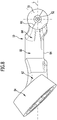
- FIG. 1 An in Figs. 1 to 3
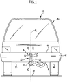
- the illustrated first embodiment of a trailer coupling according to the invention for a motor vehicle K, in particular a passenger vehicle, illustrated in FIG Fig. 1 comprises a ball neck designated as a whole with 10, which has a ball shoulder 14 at a first end 12 which carries a coupling ball 16.
- the ball neck 10 for its part then extends from the first end 12 to a second end 22, which is supported by means of a pivot bearing unit designated as a whole with 24 so as to be pivotable about a pivot axis 26 on a carrier unit of the trailer coupling designated as a whole with 32, the carrier unit 32 has a support element 34 which is firmly connected to a cross member 36 which extends transversely to a longitudinal direction of the vehicle approximately parallel to a rear bumper unit 42 of the motor vehicle K and is connected to a rear area H of the motor vehicle body KA, for example via connecting elements not shown in the drawing.
- the bumper unit 42 is arranged so that it covers the cross member 36 on a side facing away from the rear side H of the motor vehicle body KA.
- the ball neck 10 extends from the pivot bearing unit 24, which is also covered by the bumper unit 42, under the lower bumper edge 46 and then upwards away from a roadway F so that the coupling ball 16 is at a defined height above the roadway F. and is positioned behind the bumper unit 42 as seen in the direction of travel.
- the ball neck 10 can be moved from the in Fig. 1 and 2 Pivot illustrated working position A into a rest position R, in which the coupling ball 16 is moved under the lower bumper edge 46, in such a way that the ball neck 10 is positioned between the cross member 36 and the bumper unit 42 and largely covered by the bumper unit 42 in the rest position R. is.
- the pivot bearing unit 24 is preferably designed so that the movement of the ball neck 10 between the working position A and the rest position R is only possible by a pivoting movement about the pivot axis 26, the pivot axis 26 running obliquely to a vertical vehicle longitudinal center plane FL.
- the vehicle longitudinal center plane FL runs in the working position A of the ball neck 10 in such a way that a coupling ball center axis 52 of the coupling ball 16 lies in this, to which both the coupling ball 16 and the ball shoulder 14 are rotationally symmetrical ( Fig. 1 and 2 ).
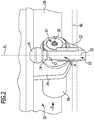
- the pivot bearing unit 24 is preferably designed such that a pivot body 54 connected to the second end 22 of the ball neck 10 forms an outer body of the pivot bearing unit 24, which can be pivoted about the pivot axis 26 together with the ball neck 10.
- the pivot bearing unit 24 is, for example, additionally provided with a drive unit 56 ( Fig. 2 and 3 ) can be driven, which has at least one electric drive motor or possibly two electric drive motors, which serve on the one hand to drive a locking device, not shown in the drawing, of the pivot bearing unit 24 and to execute the pivoting movement of the pivot body 54 about the pivot axis 26.
- a drive unit 56 Fig. 2 and 3
- the pivot bearing unit 24 has at least one electric drive motor or possibly two electric drive motors, which serve on the one hand to drive a locking device, not shown in the drawing, of the pivot bearing unit 24 and to execute the pivoting movement of the pivot body 54 about the pivot axis 26.
- the ball neck 10 is preferably designed such that it comprises a first ball neck section 62 adjoining the ball shoulder 14 in the area of the first end 12, which extends away from the ball shoulder 14 in the direction of the coupling ball center axis 52, preferably parallel to it.
- This first ball neck section 62 is followed by a second ball neck section 64, which is curved to the coupling ball central axis 52 and in the working position A extends laterally away from the coupling ball central axis 52 in the direction of the rear area H of the vehicle body KA.
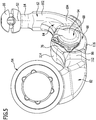
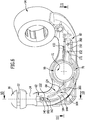
- the second ball neck section 64 merges at its end opposite the first ball neck section 62 into a third ball neck section 66 which carries a contact unit 68 and preferably has a receptacle 72 for the contact unit ( Fig. 5 and 7th ).
- the receptacle 72 can be designed as a flange attachment on which the contact unit can be mounted.
- the receptacle 72 is an opening 74 integrated into the third ball neck section 66, which is enclosed by an annular body 76 formed by the third ball neck section 66 and which receives the contact unit 68.
- This third ball neck section 66 is in turn adjoined by a fourth ball neck section 82, which extends as far as the second end 22 of the ball neck 10 and is, for example, a curved ball neck section that merges into the swivel body 54.
- the first ball neck section 62, the second ball neck section 64, the third ball neck section 66 and the fourth ball neck section 82 preferably form a one-piece part, which preferably also merges in one piece into the ball shoulder 14 and the coupling ball 16 and, on the other hand, merges into the swivel body 54 in one piece.
- the ball neck sections 62, 64, 66 and 82 can either be symmetrical or, as in the exemplary embodiment according to FIG Fig. 6 shown, be formed asymmetrically to the longitudinal center plane L and thus run asymmetrically to this at least in sections.
- the third ball neck section 66 is designed in such a way that it has a flange surface 84 on one side for supporting a mounting flange 86 of the contact unit 68, which has, for example, an access cover 94 mounted on the mounting flange 86, which extends with a housing body through the opening 74 and opens a side opposite the mounting flange 86 is closed by a rear cover 96.
- the ball neck 10 in the area of the first ball neck section 62, in the area of the second ball neck section 64 and in the area of the fourth ball neck section 82 has a longitudinal side contour 102, 104 or 112, which between an upper side contour 114 and 114 facing away from the roadway F in the working position A an underside contour 116 of the ball neck 110 facing a roadway F in the working position A is convexly curved or approximately flat and thus free of depressions.
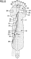
- longitudinal side contours 122, 124 and 132 are provided, which, starting from an outer contours present in these ball neck sections 62, 64 and 82 142, 144 and 152 have recesses 162, 164 and 172 extending into the respective ball neck section 62, 64 and 82, the recess 162 extending deepest into the first ball neck section 62 starting from the outer contour 142, namely up to a recess bottom 182, which is arranged at a distance AL from the longitudinal center plane L ( Fig. 10 ), which corresponds to at least one tenth, even better at least two tenths of a radius RK of the coupling ball 16.
- a recess bottom 184 of the recess 164 lies at a distance from the longitudinal center plane L which is greater than half of a radius RK of the coupling ball 16.
- the recess runs 164 from the recess 162 to the receptacle 72 for the contact unit 68.
- the recess 172 with a recess bottom 192 also runs at a distance from the longitudinal center plane L of the ball neck 10, which corresponds to at least two thirds of the radius of the coupling ball 16.
- the coupling ball 16 is provided with an annular groove 204 encircling the coupling ball central axis 52, in which the driving ring 202 is rotatably guided and supported relative to the coupling ball 16, for receiving a rotational position of a ball coupling engaging the coupling ball 16.
- the annular groove 204 lies within a geometric outer spherical surface 206, while the driver ring 202 at least in some areas with driver bodies 208 protrudes beyond the outer spherical surface 206 radially to the coupling ball center axis 52 in order to ensure that the driver ring 202 interacts with the ball coupling engaging on the coupling ball 16, in order to rotate the driving ring 202 when the ball coupling is rotated about the central axis 52 of the coupling ball.
- a receiving space 212 is provided within the outer spherical surface 206 and within the annular groove 204, in which a sensor unit 214 is arranged for detecting the rotational positions of the driving ring 202, the rotational positions of the driving ring 202 being detected, for example, via magnetic or inductive interaction according to the known principles of rotation angle measuring units.
- the sensor unit 214 together with the driver ring 202 forms a kink angle detection unit 216 with which the position of the ball coupling engaging on the coupling ball 16 can be detected in relation to the coupling ball center axis 52 as the axis of rotation.
- the receiving space 212 preferably extends from the annular groove 204 to the coupling ball central axis 52.
- a channel 222 penetrating both the coupling ball 16 and the ball shoulder 14 and the first ball neck section 62 is provided, which is inside the coupling ball 16 communicates with the receiving space 212, that is to say passes through it or at least affects it, and extends as far as an exit 224, which lies in the recess 162 of the first ball neck section 62.
- the channel 222 is preferably designed such that it runs coaxially to a channel axis 226 which intersects the longitudinal center plane L of the ball neck 10 within the coupling ball 16, preferably intersects such that the channel axis 226 also intersects the coupling ball center axis 52 at the same time.
- channel axis 226, starting from the point of intersection with the longitudinal center plane L and possibly also the coupling ball center axis 52, runs obliquely to the longitudinal center plane L or to the coupling ball center axis 52 in the direction of the exit 224 such that the distance from the longitudinal center plane L or the coupling ball center axis 52 increases with increasing course in the direction of output 224 increases as shown in FIG Fig. 9 shown.
- the channel axis 226 of the channel 222 preferably runs in such a way that it intersects the recess 162 in the area of its recess bottom 182, so that the outlet 224 lies partially in the area of the recess bottom 182 and partially in the area of a recess side wall 232 which rises above the respective recess bottom 182 .
- Such a course of the channel 222 allows the distance of the channel axis 226 from the longitudinal center plane L and possibly also the coupling ball center axis 52 to be kept as small as possible in order to provide a sufficiently thick wall 234 surrounding the channel 222, particularly in the area of the ball attachment 14 have, which is essential for the stability of the connection between the coupling ball 16 and the first end 12 of the ball neck 10.
- the channel 222 is designed as a bore 236 which is coaxial with the channel axis 226 and which, starting from a flattening 242 of the coupling ball 16 opposite the ball shoulder 14, passes through the entire coupling ball 16 and also through the ball shoulder 14 and the first ball neck section 62 to the exit 224 in the recess 162.
- a blind hole 243 starting from the flattening 242 in the coupling ball 16 coaxially to the coupling ball central axis 52, is preferably drilled, the diameter of which is in particular larger than that of the channel bore 236 made subsequently, for example by a factor of at least 1.2, more preferably at least 1.4, greater than the channel 222.
- the channel bore 236 running obliquely to the coupling ball central axis 52 can be implemented without any problems as an oblique bore starting from the base 246 of the blind hole 243, which then extends to the recess 162.
- the recess 244 produced by the blind hole 243 extends, starting from the flattening 242, only with a depth in the direction of the coupling ball central axis 52 that is a maximum of 0.7 times, even better a maximum of 0.8 times the diameter of the blind hole or the Recess 244 is.
- the channel 222 thus comprises a total of a recess 244 formed by producing the blind hole 243 and the channel bore 236 adjoining the recess 244 with the formation of a step.
- the recess 244 immediately adjoining the flat area 242 is provided with cylindrical walls 248 which are coaxial with the coupling ball central axis 52 and which receive a sealing plug 226 so that neither dirt nor moisture in the channel 222 can penetrate.
- An electrical line 252 leading away from the sensor unit 214 runs, as in FIG Fig. 7 and Fig. 10 shown, through the channel 222 to the outlet 224 and then in the recess 162 to the recess 164 to the contact unit 68 and from the contact unit 68 in the form of a continuing wiring harness 254 in the direction of the pivot bearing unit 224 and from there to a vehicle-side connection unit.
- the electrical line 252 can run in the recesses 162 and 164 as far as the contact unit 68, and thereby rests on the corresponding recess bottom 182 and 184, the electrical line 252 is protected against damage, in particular against damage to the first ball neck section 62 or the securing ropes encompassing the second ball neck section 64 or other elements engaging them.
- the covers 262, 264 can preferably be fixed by means of holes 266, 268 with corresponding fixing pins, for example provided with Christmas tree structures, starting from the respective recess bottom 182 and 184 into the ball neck.
Landscapes
- Engineering & Computer Science (AREA)
- Transportation (AREA)
- Mechanical Engineering (AREA)
- Pivots And Pivotal Connections (AREA)
Claims (15)
- Attelage pour véhicules automobiles (K), en particulier pour véhicules particuliers, comprenant un col de cygne (10) portant, sur une première extrémité (12), un épaulement de rotule (14) et une boule d'attelage (16) maintenue par l'épaulement de rotule (14), une unité support (32) pouvant être montée de manière fixe sur un côté arrière (H) d'une carrosserie de véhicule (KA), une unité de palier (24) disposée sur l'unité support (32) et au moyen de laquelle le col de cygne (10) est positionné de manière mobile, avec une deuxième extrémité (22), sur l'unité support (32) entre une position de travail (A) et une position de repos (R), et un capteur (214) disposé dans la boule d'attelage (16) et vers lequel est dirigé un câble électrique (252) qui passe, du moins par endroits, dans un canal (222) qui traverse en partie l'épaulement de rotule (14) et le col de cygne (10) et qui s'étend depuis l'intérieur de la boule d'attelage (16) jusqu'à une sortie (224) sur le col de cygne (10) en traversant l'épaulement de rotule (14), le canal (222) étant oblique par rapport à l'axe médian (52) de la boule d'attelage, coupant un axe médian (52) de la boule d'attelage à l'intérieur de celle-ci (16) et étant dirigé vers un creux (162) dans le col de cygne (16) se terminant à distance de l'axe médian (52) de la boule d'attelage et pénétrant dans le col de cygne (16) depuis un contour extérieur (122) de celui-ci, caractérisé en ce que la sortie (224) se trouve dans le creux (162).
- Attelage selon la revendication 1, caractérisé en ce que le canal (222) part de l'intérieur de la boule d'attelage (16) et passe à une distance croissante de l'axe médian (52) de celle-ci sans se croiser, et en ce que, en particulier, le canal (222) est oblique par rapport à l'axe médian (52) de la boule d'attelage et coupe alors l'axe médian (52) de la boule d'attelage à l'intérieur de celle-ci (16).
- Attelage selon l'une quelconque des revendications précédentes, caractérisé en ce que la boule d'attelage (16) présente un évidement coaxial (244) s'insérant depuis un côté opposé à l'épaulement de rotule (14) dans ce côté, en particulier par rapport à l'axe médian (52) de la boule d'attelage, et en ce que le canal (222) part de l'évidement (244) en oblique par rapport à l'axe médian (52) de la boule d'attelage jusqu'au creux (162).
- Attelage selon l'une quelconque des revendications précédentes, caractérisé en ce que le canal (222) est oblique par rapport à un plan médian longitudinal (L) traversant l'axe médian (52) de la boule d'attelage.
- Attelage selon l'une quelconque des revendications précédentes, caractérisé en ce que le creux (162) pénètre, à partir du contour d'un côté longitudinal (122) du col de cygne (10), dans le col de cygne (10).
- Attelage selon l'une quelconque des revendications précédentes, caractérisé en ce qu'un axe de canal (226), par rapport auquel le canal (222) est coaxial, coupe le creux (162) à proximité d'un fond de creux (182), et en ce que, en particulier, l'axe de canal (226) coupe le fond de creux (182).
- Attelage selon l'une quelconque des revendications précédentes, caractérisé en ce que le canal (226) traverse une paroi latérale (232) du creux.
- Attelage selon l'une quelconque des revendications précédentes, caractérisé en ce que la sortie (224) du canal (222) traverse aussi bien une paroi latérale (232) du creux qu'un fond (182) du creux (162) .
- Attelage selon l'une quelconque des revendications précédentes, caractérisé en ce que le fond de creux (182) présente une distance par rapport au plan médian longitudinal (L) supérieure à un dixième d'un rayon (RK) de la boule d'attelage (16).
- Attelage selon l'une quelconque des revendications précédentes, caractérisé en ce que le col de cygne (10) présente un premier tronçon (62) partant de l'épaulement de rotule (14) et se dirigeant vers l'axe médian (52) de la boule d'attelage, et en ce que, en particulier, le creux (162) est disposé dans le premier tronçon (62) du col de cygne.
- Attelage selon la revendication 10, caractérisé en ce que le creux (162) part d'un contour latéral longitudinal (122) du premier tronçon (162) du col de cygne, se dirige vers le plan médian longitudinal (L) et pénètre dans le col de cygne (10).
- Attelage selon l'une quelconque des revendications précédentes, caractérisé en ce que le col de cygne (10) présente un deuxième tronçon (64) adjacent au premier tronçon (62) du col de cygne et cintré par rapport à l'axe médian (52) de la boule d'attelage, et en ce que, en particulier, le deuxième tronçon (64) de col de cygne présente un creux (164) adjacent au creux (162) dans le premier tronçon (62) de col de cygne.
- Attelage selon l'une quelconque des revendications précédentes, caractérisé en ce que le col de cygne (10) présente un troisième tronçon (66) adjacent au deuxième tronçon (64) de col de cygne et portant une unité de contact (68), en ce que, en particulier, le troisième tronçon (66) de col de cygne présente un logement (72), aménagé dans celui-ci, destiné à l'unité de contact (92), et en ce que, en particulier, le deuxième creux (164) est dirigé vers l'unité de contact (68) dans le troisième tronçon (66) de col de cygne.
- Attelage selon l'une quelconque des revendications précédentes, caractérisé en ce que le col de cygne (10) présente un quatrième tronçon (82) adjacent au troisième tronçon (66) de col de cygne et se transformant en un élément (54) de l'unité de palier (24), et en ce que, en particulier, le quatrième tronçon (82) de col de cygne présente un creux (172).
- Attelage selon l'une quelconque des revendications précédentes, caractérisé en ce que le capteur (214) est un élément de l'unité de détection de l'angle de pliage (216), en ce que, en particulier, l'unité de détection de l'angle de pliage (216) présente une bague d'entraînement (202) positionnée de manière rotatoire sur la boule d'attelage (16), et en ce que, en particulier, l'entraîneur est en forme de bague d'entraînement (202) et est disposé et guidé, de manière rotative, dans une rainure annulaire (204) faisant concentriquement le tour sur un côté extérieur de la boule d'attelage (16) et, en particulier, par rapport à l'axe médian de la boule d'attelage.
Applications Claiming Priority (1)
| Application Number | Priority Date | Filing Date | Title |
|---|---|---|---|
| DE102015112741.5A DE102015112741A1 (de) | 2015-08-03 | 2015-08-03 | Anhängekupplung |
Publications (3)
| Publication Number | Publication Date |
|---|---|
| EP3127725A1 EP3127725A1 (fr) | 2017-02-08 |
| EP3127725B1 true EP3127725B1 (fr) | 2020-10-07 |
| EP3127725B2 EP3127725B2 (fr) | 2024-01-03 |
Family
ID=56550107
Family Applications (1)
| Application Number | Title | Priority Date | Filing Date |
|---|---|---|---|
| EP16180963.7A Active EP3127725B2 (fr) | 2015-08-03 | 2016-07-25 | Attelage |
Country Status (2)
| Country | Link |
|---|---|
| EP (1) | EP3127725B2 (fr) |
| DE (1) | DE102015112741A1 (fr) |
Families Citing this family (2)
| Publication number | Priority date | Publication date | Assignee | Title |
|---|---|---|---|---|
| DE102017117168A1 (de) * | 2017-02-23 | 2018-08-23 | Westfalia-Automotive Gmbh | Anhängekupplung mit einem Kugelhals und einer Kupplungskugel sowie Verfahren zu deren Herstellung |
| DE102017109488A1 (de) | 2017-05-03 | 2018-11-08 | ACPS Automotive GmbH | An einem Heckbereich eines Kraftfahrzeugs montierbare Halteeinrichtung |
Citations (8)
| Publication number | Priority date | Publication date | Assignee | Title |
|---|---|---|---|---|
| GB465020A (en) | 1936-08-13 | 1937-04-29 | Franz Knoebel Junior | An improved ball joint coupling for trailers of motor vehicles and the like |
| US5159312A (en) | 1991-04-01 | 1992-10-27 | Engle Edgar R | Double switch safety system and signaling device for a trailer hitch coupling |
| DE102010029414A1 (de) | 2010-05-27 | 2011-12-01 | Scambia Industrial Developments Aktiengesellschaft | Anhängekupplung |
| DE102010045519A1 (de) | 2010-09-15 | 2012-03-15 | Volkswagen Ag | Anhängerkupplung und Zugfahrzeug mit dieser Anhängerkupplung |
| EP2567837A1 (fr) | 2011-09-12 | 2013-03-13 | Scambia Holdings Cyprus Limited | Unité de support |
| DE202013000779U1 (de) | 2012-10-26 | 2014-01-29 | Westfalia-Automotive Gmbh | Anhängekupplung mit einem Kupplungsarm |
| EP2952367A1 (fr) | 2014-06-06 | 2015-12-09 | Scambia Holdings Cyprus Limited | Attelage |
| WO2015185358A1 (fr) | 2014-06-05 | 2015-12-10 | Scambia Holdings Cyprus Limited | Accouplement d'attelage |
Family Cites Families (2)
| Publication number | Priority date | Publication date | Assignee | Title |
|---|---|---|---|---|
| EP2905155B1 (fr) * | 2010-08-06 | 2021-07-28 | WESTFALIA - Automotive GmbH | Attelage doté d'un capteur |
| DE102012001921A1 (de) † | 2012-02-02 | 2013-08-08 | Westfalia-Automotive Gmbh | Anhängekupplung mit einem Sensor |
-
2015
- 2015-08-03 DE DE102015112741.5A patent/DE102015112741A1/de active Pending
-
2016
- 2016-07-25 EP EP16180963.7A patent/EP3127725B2/fr active Active
Patent Citations (8)
| Publication number | Priority date | Publication date | Assignee | Title |
|---|---|---|---|---|
| GB465020A (en) | 1936-08-13 | 1937-04-29 | Franz Knoebel Junior | An improved ball joint coupling for trailers of motor vehicles and the like |
| US5159312A (en) | 1991-04-01 | 1992-10-27 | Engle Edgar R | Double switch safety system and signaling device for a trailer hitch coupling |
| DE102010029414A1 (de) | 2010-05-27 | 2011-12-01 | Scambia Industrial Developments Aktiengesellschaft | Anhängekupplung |
| DE102010045519A1 (de) | 2010-09-15 | 2012-03-15 | Volkswagen Ag | Anhängerkupplung und Zugfahrzeug mit dieser Anhängerkupplung |
| EP2567837A1 (fr) | 2011-09-12 | 2013-03-13 | Scambia Holdings Cyprus Limited | Unité de support |
| DE202013000779U1 (de) | 2012-10-26 | 2014-01-29 | Westfalia-Automotive Gmbh | Anhängekupplung mit einem Kupplungsarm |
| WO2015185358A1 (fr) | 2014-06-05 | 2015-12-10 | Scambia Holdings Cyprus Limited | Accouplement d'attelage |
| EP2952367A1 (fr) | 2014-06-06 | 2015-12-09 | Scambia Holdings Cyprus Limited | Attelage |
Also Published As
| Publication number | Publication date |
|---|---|
| EP3127725A1 (fr) | 2017-02-08 |
| DE102015112741A1 (de) | 2017-02-09 |
| EP3127725B2 (fr) | 2024-01-03 |
Similar Documents
| Publication | Publication Date | Title |
|---|---|---|
| EP3632714B1 (fr) | Attelage doté d'un capteur | |
| EP3034335B1 (fr) | Attelage | |
| EP2952368B1 (fr) | Attelage | |
| EP1902871B2 (fr) | Attelage | |
| DE102004024333B4 (de) | Steckverbindungen | |
| EP2175158B1 (fr) | Capteur d'usure de garniture de friction | |
| DE102013215896A1 (de) | Normal ausfahrbarer, bündig abschliessender Türgriff | |
| EP3127725B1 (fr) | Attelage | |
| DE10243045A1 (de) | Anhängerkupplung | |
| WO2022008238A1 (fr) | Composant de châssis doté d'une partie interne de joint | |
| EP2385596B1 (fr) | Dispositif comprenant un tube et un boîtier pouvant être monté sur le tube pour un boîtier de charge électrique pour véhicules électriques | |
| EP3456555A1 (fr) | Attelage de remorque | |
| DE202013000779U1 (de) | Anhängekupplung mit einem Kupplungsarm | |
| DE69728748T2 (de) | Einstellbare abstützvorrichtung für ein kinderfahrzeug | |
| DE10327706B3 (de) | Hilfskraftbetätigte Anhängekupplung für Kraftfahrzeuge | |
| EP2941358B1 (fr) | Véhicule à moteur | |
| DE102007029448A1 (de) | Werkzeug | |
| DE102018133310A1 (de) | Fahrzeugtürgriff | |
| EP2829422B1 (fr) | Système d'attelage pour véhicules automobiles | |
| DE102007012118B4 (de) | Einstellpuffer für Kraftfahrzeuge | |
| EP3456554B1 (fr) | Attelage de remorque | |
| EP3456553B1 (fr) | Attelage de remorque | |
| DE102011107236A1 (de) | Schraubelement | |
| DE29825216U1 (de) | Kontakteinheit und Anhängekupplung für Kraftfahrzeuge mit einer Kontakteinheit | |
| EP3290239B1 (fr) | Dispositif d'amortissement d'oscillation pour remorques de véhicule |
Legal Events
| Date | Code | Title | Description |
|---|---|---|---|
| PUAI | Public reference made under article 153(3) epc to a published international application that has entered the european phase |
Free format text: ORIGINAL CODE: 0009012 |
|
| STAA | Information on the status of an ep patent application or granted ep patent |
Free format text: STATUS: THE APPLICATION HAS BEEN PUBLISHED |
|
| AK | Designated contracting states |
Kind code of ref document: A1 Designated state(s): AL AT BE BG CH CY CZ DE DK EE ES FI FR GB GR HR HU IE IS IT LI LT LU LV MC MK MT NL NO PL PT RO RS SE SI SK SM TR |
|
| AX | Request for extension of the european patent |
Extension state: BA ME |
|
| STAA | Information on the status of an ep patent application or granted ep patent |
Free format text: STATUS: REQUEST FOR EXAMINATION WAS MADE |
|
| 17P | Request for examination filed |
Effective date: 20170802 |
|
| RBV | Designated contracting states (corrected) |
Designated state(s): AL AT BE BG CH CY CZ DE DK EE ES FI FR GB GR HR HU IE IS IT LI LT LU LV MC MK MT NL NO PL PT RO RS SE SI SK SM TR |
|
| RAP1 | Party data changed (applicant data changed or rights of an application transferred) |
Owner name: BOSAL ACPS HOLDING 2 B.V. |
|
| STAA | Information on the status of an ep patent application or granted ep patent |
Free format text: STATUS: EXAMINATION IS IN PROGRESS |
|
| 17Q | First examination report despatched |
Effective date: 20190621 |
|
| RAP1 | Party data changed (applicant data changed or rights of an application transferred) |
Owner name: ACPS AUTOMOTIVE GMBH |
|
| GRAP | Despatch of communication of intention to grant a patent |
Free format text: ORIGINAL CODE: EPIDOSNIGR1 |
|
| STAA | Information on the status of an ep patent application or granted ep patent |
Free format text: STATUS: GRANT OF PATENT IS INTENDED |
|
| INTG | Intention to grant announced |
Effective date: 20200430 |
|
| GRAS | Grant fee paid |
Free format text: ORIGINAL CODE: EPIDOSNIGR3 |
|
| GRAA | (expected) grant |
Free format text: ORIGINAL CODE: 0009210 |
|
| STAA | Information on the status of an ep patent application or granted ep patent |
Free format text: STATUS: THE PATENT HAS BEEN GRANTED |
|
| AK | Designated contracting states |
Kind code of ref document: B1 Designated state(s): AL AT BE BG CH CY CZ DE DK EE ES FI FR GB GR HR HU IE IS IT LI LT LU LV MC MK MT NL NO PL PT RO RS SE SI SK SM TR |
|
| REG | Reference to a national code |
Ref country code: GB Ref legal event code: FG4D Free format text: NOT ENGLISH |
|
| REG | Reference to a national code |
Ref country code: AT Ref legal event code: REF Ref document number: 1320793 Country of ref document: AT Kind code of ref document: T Effective date: 20201015 Ref country code: CH Ref legal event code: EP |
|
| REG | Reference to a national code |
Ref country code: IE Ref legal event code: FG4D Free format text: LANGUAGE OF EP DOCUMENT: GERMAN |
|
| REG | Reference to a national code |
Ref country code: DE Ref legal event code: R096 Ref document number: 502016011368 Country of ref document: DE |
|
| REG | Reference to a national code |
Ref country code: NL Ref legal event code: FP |
|
| PG25 | Lapsed in a contracting state [announced via postgrant information from national office to epo] |
Ref country code: NO Free format text: LAPSE BECAUSE OF FAILURE TO SUBMIT A TRANSLATION OF THE DESCRIPTION OR TO PAY THE FEE WITHIN THE PRESCRIBED TIME-LIMIT Effective date: 20210107 Ref country code: RS Free format text: LAPSE BECAUSE OF FAILURE TO SUBMIT A TRANSLATION OF THE DESCRIPTION OR TO PAY THE FEE WITHIN THE PRESCRIBED TIME-LIMIT Effective date: 20201007 Ref country code: PT Free format text: LAPSE BECAUSE OF FAILURE TO SUBMIT A TRANSLATION OF THE DESCRIPTION OR TO PAY THE FEE WITHIN THE PRESCRIBED TIME-LIMIT Effective date: 20210208 Ref country code: GR Free format text: LAPSE BECAUSE OF FAILURE TO SUBMIT A TRANSLATION OF THE DESCRIPTION OR TO PAY THE FEE WITHIN THE PRESCRIBED TIME-LIMIT Effective date: 20210108 Ref country code: FI Free format text: LAPSE BECAUSE OF FAILURE TO SUBMIT A TRANSLATION OF THE DESCRIPTION OR TO PAY THE FEE WITHIN THE PRESCRIBED TIME-LIMIT Effective date: 20201007 |
|
| REG | Reference to a national code |
Ref country code: LT Ref legal event code: MG4D |
|
| PG25 | Lapsed in a contracting state [announced via postgrant information from national office to epo] |
Ref country code: BG Free format text: LAPSE BECAUSE OF FAILURE TO SUBMIT A TRANSLATION OF THE DESCRIPTION OR TO PAY THE FEE WITHIN THE PRESCRIBED TIME-LIMIT Effective date: 20210107 Ref country code: IS Free format text: LAPSE BECAUSE OF FAILURE TO SUBMIT A TRANSLATION OF THE DESCRIPTION OR TO PAY THE FEE WITHIN THE PRESCRIBED TIME-LIMIT Effective date: 20210207 Ref country code: SE Free format text: LAPSE BECAUSE OF FAILURE TO SUBMIT A TRANSLATION OF THE DESCRIPTION OR TO PAY THE FEE WITHIN THE PRESCRIBED TIME-LIMIT Effective date: 20201007 Ref country code: PL Free format text: LAPSE BECAUSE OF FAILURE TO SUBMIT A TRANSLATION OF THE DESCRIPTION OR TO PAY THE FEE WITHIN THE PRESCRIBED TIME-LIMIT Effective date: 20201007 Ref country code: LV Free format text: LAPSE BECAUSE OF FAILURE TO SUBMIT A TRANSLATION OF THE DESCRIPTION OR TO PAY THE FEE WITHIN THE PRESCRIBED TIME-LIMIT Effective date: 20201007 Ref country code: ES Free format text: LAPSE BECAUSE OF FAILURE TO SUBMIT A TRANSLATION OF THE DESCRIPTION OR TO PAY THE FEE WITHIN THE PRESCRIBED TIME-LIMIT Effective date: 20201007 |
|
| PG25 | Lapsed in a contracting state [announced via postgrant information from national office to epo] |
Ref country code: HR Free format text: LAPSE BECAUSE OF FAILURE TO SUBMIT A TRANSLATION OF THE DESCRIPTION OR TO PAY THE FEE WITHIN THE PRESCRIBED TIME-LIMIT Effective date: 20201007 |
|
| REG | Reference to a national code |
Ref country code: DE Ref legal event code: R026 Ref document number: 502016011368 Country of ref document: DE |
|
| PLBI | Opposition filed |
Free format text: ORIGINAL CODE: 0009260 |
|
| PLAX | Notice of opposition and request to file observation + time limit sent |
Free format text: ORIGINAL CODE: EPIDOSNOBS2 |
|
| PG25 | Lapsed in a contracting state [announced via postgrant information from national office to epo] |
Ref country code: CZ Free format text: LAPSE BECAUSE OF FAILURE TO SUBMIT A TRANSLATION OF THE DESCRIPTION OR TO PAY THE FEE WITHIN THE PRESCRIBED TIME-LIMIT Effective date: 20201007 Ref country code: EE Free format text: LAPSE BECAUSE OF FAILURE TO SUBMIT A TRANSLATION OF THE DESCRIPTION OR TO PAY THE FEE WITHIN THE PRESCRIBED TIME-LIMIT Effective date: 20201007 Ref country code: SM Free format text: LAPSE BECAUSE OF FAILURE TO SUBMIT A TRANSLATION OF THE DESCRIPTION OR TO PAY THE FEE WITHIN THE PRESCRIBED TIME-LIMIT Effective date: 20201007 Ref country code: LT Free format text: LAPSE BECAUSE OF FAILURE TO SUBMIT A TRANSLATION OF THE DESCRIPTION OR TO PAY THE FEE WITHIN THE PRESCRIBED TIME-LIMIT Effective date: 20201007 Ref country code: RO Free format text: LAPSE BECAUSE OF FAILURE TO SUBMIT A TRANSLATION OF THE DESCRIPTION OR TO PAY THE FEE WITHIN THE PRESCRIBED TIME-LIMIT Effective date: 20201007 Ref country code: SK Free format text: LAPSE BECAUSE OF FAILURE TO SUBMIT A TRANSLATION OF THE DESCRIPTION OR TO PAY THE FEE WITHIN THE PRESCRIBED TIME-LIMIT Effective date: 20201007 |
|
| 26 | Opposition filed |
Opponent name: WESTFALIA - AUTOMOTIVE GMBH Effective date: 20210705 |
|
| PG25 | Lapsed in a contracting state [announced via postgrant information from national office to epo] |
Ref country code: DK Free format text: LAPSE BECAUSE OF FAILURE TO SUBMIT A TRANSLATION OF THE DESCRIPTION OR TO PAY THE FEE WITHIN THE PRESCRIBED TIME-LIMIT Effective date: 20201007 |
|
| PG25 | Lapsed in a contracting state [announced via postgrant information from national office to epo] |
Ref country code: AL Free format text: LAPSE BECAUSE OF FAILURE TO SUBMIT A TRANSLATION OF THE DESCRIPTION OR TO PAY THE FEE WITHIN THE PRESCRIBED TIME-LIMIT Effective date: 20201007 Ref country code: IT Free format text: LAPSE BECAUSE OF FAILURE TO SUBMIT A TRANSLATION OF THE DESCRIPTION OR TO PAY THE FEE WITHIN THE PRESCRIBED TIME-LIMIT Effective date: 20201007 |
|
| PG25 | Lapsed in a contracting state [announced via postgrant information from national office to epo] |
Ref country code: SI Free format text: LAPSE BECAUSE OF FAILURE TO SUBMIT A TRANSLATION OF THE DESCRIPTION OR TO PAY THE FEE WITHIN THE PRESCRIBED TIME-LIMIT Effective date: 20201007 |
|
| PLBB | Reply of patent proprietor to notice(s) of opposition received |
Free format text: ORIGINAL CODE: EPIDOSNOBS3 |
|
| REG | Reference to a national code |
Ref country code: CH Ref legal event code: PL |
|
| PG25 | Lapsed in a contracting state [announced via postgrant information from national office to epo] |
Ref country code: MC Free format text: LAPSE BECAUSE OF FAILURE TO SUBMIT A TRANSLATION OF THE DESCRIPTION OR TO PAY THE FEE WITHIN THE PRESCRIBED TIME-LIMIT Effective date: 20201007 |
|
| REG | Reference to a national code |
Ref country code: BE Ref legal event code: MM Effective date: 20210731 |
|
| PG25 | Lapsed in a contracting state [announced via postgrant information from national office to epo] |
Ref country code: LI Free format text: LAPSE BECAUSE OF NON-PAYMENT OF DUE FEES Effective date: 20210731 Ref country code: CH Free format text: LAPSE BECAUSE OF NON-PAYMENT OF DUE FEES Effective date: 20210731 |
|
| PG25 | Lapsed in a contracting state [announced via postgrant information from national office to epo] |
Ref country code: IS Free format text: LAPSE BECAUSE OF FAILURE TO SUBMIT A TRANSLATION OF THE DESCRIPTION OR TO PAY THE FEE WITHIN THE PRESCRIBED TIME-LIMIT Effective date: 20210207 Ref country code: LU Free format text: LAPSE BECAUSE OF NON-PAYMENT OF DUE FEES Effective date: 20210725 |
|
| PG25 | Lapsed in a contracting state [announced via postgrant information from national office to epo] |
Ref country code: IE Free format text: LAPSE BECAUSE OF NON-PAYMENT OF DUE FEES Effective date: 20210725 Ref country code: BE Free format text: LAPSE BECAUSE OF NON-PAYMENT OF DUE FEES Effective date: 20210731 |
|
| REG | Reference to a national code |
Ref country code: AT Ref legal event code: MM01 Ref document number: 1320793 Country of ref document: AT Kind code of ref document: T Effective date: 20210725 |
|
| PG25 | Lapsed in a contracting state [announced via postgrant information from national office to epo] |
Ref country code: AT Free format text: LAPSE BECAUSE OF NON-PAYMENT OF DUE FEES Effective date: 20210725 |
|
| REG | Reference to a national code |
Ref country code: DE Ref legal event code: R081 Ref document number: 502016011368 Country of ref document: DE Owner name: ACPS AUTOMOTIVE GMBH, DE Free format text: FORMER OWNER: ACPS AUTOMOTIVE GMBH, 71706 MARKGROENINGEN, DE |
|
| RAP4 | Party data changed (patent owner data changed or rights of a patent transferred) |
Owner name: ACPS AUTOMOTIVE GMBH |
|
| PG25 | Lapsed in a contracting state [announced via postgrant information from national office to epo] |
Ref country code: HU Free format text: LAPSE BECAUSE OF FAILURE TO SUBMIT A TRANSLATION OF THE DESCRIPTION OR TO PAY THE FEE WITHIN THE PRESCRIBED TIME-LIMIT; INVALID AB INITIO Effective date: 20160725 |
|
| P01 | Opt-out of the competence of the unified patent court (upc) registered |
Effective date: 20230517 |
|
| APAH | Appeal reference modified |
Free format text: ORIGINAL CODE: EPIDOSCREFNO |
|
| APBM | Appeal reference recorded |
Free format text: ORIGINAL CODE: EPIDOSNREFNO |
|
| APBP | Date of receipt of notice of appeal recorded |
Free format text: ORIGINAL CODE: EPIDOSNNOA2O |
|
| PG25 | Lapsed in a contracting state [announced via postgrant information from national office to epo] |
Ref country code: CY Free format text: LAPSE BECAUSE OF FAILURE TO SUBMIT A TRANSLATION OF THE DESCRIPTION OR TO PAY THE FEE WITHIN THE PRESCRIBED TIME-LIMIT Effective date: 20201007 |
|
| APBU | Appeal procedure closed |
Free format text: ORIGINAL CODE: EPIDOSNNOA9O |
|
| PGFP | Annual fee paid to national office [announced via postgrant information from national office to epo] |
Ref country code: NL Payment date: 20230719 Year of fee payment: 8 |
|
| PGFP | Annual fee paid to national office [announced via postgrant information from national office to epo] |
Ref country code: GB Payment date: 20230721 Year of fee payment: 8 |
|
| PGFP | Annual fee paid to national office [announced via postgrant information from national office to epo] |
Ref country code: FR Payment date: 20230726 Year of fee payment: 8 Ref country code: DE Payment date: 20230719 Year of fee payment: 8 |
|
| PUAH | Patent maintained in amended form |
Free format text: ORIGINAL CODE: 0009272 |
|
| STAA | Information on the status of an ep patent application or granted ep patent |
Free format text: STATUS: PATENT MAINTAINED AS AMENDED |
|
| 27A | Patent maintained in amended form |
Effective date: 20240103 |
|
| AK | Designated contracting states |
Kind code of ref document: B2 Designated state(s): AL AT BE BG CH CY CZ DE DK EE ES FI FR GB GR HR HU IE IS IT LI LT LU LV MC MK MT NL NO PL PT RO RS SE SI SK SM TR |
|
| REG | Reference to a national code |
Ref country code: DE Ref legal event code: R102 Ref document number: 502016011368 Country of ref document: DE |
|
| REG | Reference to a national code |
Ref country code: NL Ref legal event code: FP |
|
| PG25 | Lapsed in a contracting state [announced via postgrant information from national office to epo] |
Ref country code: MK Free format text: LAPSE BECAUSE OF FAILURE TO SUBMIT A TRANSLATION OF THE DESCRIPTION OR TO PAY THE FEE WITHIN THE PRESCRIBED TIME-LIMIT Effective date: 20201007 |