EP3124326A2 - Dispositif pour fermer une ouverture de boîtier optique de véhicule, boîtier optique équipé d'un tel dispositif et cordon pour ledit dispositif - Google Patents
Dispositif pour fermer une ouverture de boîtier optique de véhicule, boîtier optique équipé d'un tel dispositif et cordon pour ledit dispositif Download PDFInfo
- Publication number
- EP3124326A2 EP3124326A2 EP16181764.8A EP16181764A EP3124326A2 EP 3124326 A2 EP3124326 A2 EP 3124326A2 EP 16181764 A EP16181764 A EP 16181764A EP 3124326 A2 EP3124326 A2 EP 3124326A2
- Authority
- EP
- European Patent Office
- Prior art keywords
- cap
- cord
- bead
- opening
- housing
- Prior art date
- Legal status (The legal status is an assumption and is not a legal conclusion. Google has not performed a legal analysis and makes no representation as to the accuracy of the status listed.)
- Granted
Links
Images


Classifications
-
- B—PERFORMING OPERATIONS; TRANSPORTING
- B60—VEHICLES IN GENERAL
- B60Q—ARRANGEMENT OF SIGNALLING OR LIGHTING DEVICES, THE MOUNTING OR SUPPORTING THEREOF OR CIRCUITS THEREFOR, FOR VEHICLES IN GENERAL
- B60Q1/00—Arrangement of optical signalling or lighting devices, the mounting or supporting thereof or circuits therefor
- B60Q1/0064—Arrangement of optical signalling or lighting devices, the mounting or supporting thereof or circuits therefor with provision for maintenance, e.g. changing the light bulb
- B60Q1/007—Arrangement of optical signalling or lighting devices, the mounting or supporting thereof or circuits therefor with provision for maintenance, e.g. changing the light bulb via a removable cap
-
- B—PERFORMING OPERATIONS; TRANSPORTING
- B65—CONVEYING; PACKING; STORING; HANDLING THIN OR FILAMENTARY MATERIAL
- B65D—CONTAINERS FOR STORAGE OR TRANSPORT OF ARTICLES OR MATERIALS, e.g. BAGS, BARRELS, BOTTLES, BOXES, CANS, CARTONS, CRATES, DRUMS, JARS, TANKS, HOPPERS, FORWARDING CONTAINERS; ACCESSORIES, CLOSURES, OR FITTINGS THEREFOR; PACKAGING ELEMENTS; PACKAGES
- B65D55/00—Accessories for container closures not otherwise provided for
- B65D55/16—Devices preventing loss of removable closure members
-
- F—MECHANICAL ENGINEERING; LIGHTING; HEATING; WEAPONS; BLASTING
- F21—LIGHTING
- F21S—NON-PORTABLE LIGHTING DEVICES; SYSTEMS THEREOF; VEHICLE LIGHTING DEVICES SPECIALLY ADAPTED FOR VEHICLE EXTERIORS
- F21S43/00—Signalling devices specially adapted for vehicle exteriors, e.g. brake lamps, direction indicator lights or reversing lights
-
- F—MECHANICAL ENGINEERING; LIGHTING; HEATING; WEAPONS; BLASTING
- F21—LIGHTING
- F21S—NON-PORTABLE LIGHTING DEVICES; SYSTEMS THEREOF; VEHICLE LIGHTING DEVICES SPECIALLY ADAPTED FOR VEHICLE EXTERIORS
- F21S45/00—Arrangements within vehicle lighting devices specially adapted for vehicle exteriors, for purposes other than emission or distribution of light
- F21S45/50—Waterproofing
-
- F—MECHANICAL ENGINEERING; LIGHTING; HEATING; WEAPONS; BLASTING
- F21—LIGHTING
- F21V—FUNCTIONAL FEATURES OR DETAILS OF LIGHTING DEVICES OR SYSTEMS THEREOF; STRUCTURAL COMBINATIONS OF LIGHTING DEVICES WITH OTHER ARTICLES, NOT OTHERWISE PROVIDED FOR
- F21V11/00—Screens not covered by groups F21V1/00, F21V3/00, F21V7/00 or F21V9/00
- F21V11/16—Screens not covered by groups F21V1/00, F21V3/00, F21V7/00 or F21V9/00 using sheets without apertures, e.g. fixed
- F21V11/18—Screens not covered by groups F21V1/00, F21V3/00, F21V7/00 or F21V9/00 using sheets without apertures, e.g. fixed movable, e.g. flaps, slides
- F21V11/183—Screens not covered by groups F21V1/00, F21V3/00, F21V7/00 or F21V9/00 using sheets without apertures, e.g. fixed movable, e.g. flaps, slides pivotable
-
- F—MECHANICAL ENGINEERING; LIGHTING; HEATING; WEAPONS; BLASTING
- F21—LIGHTING
- F21V—FUNCTIONAL FEATURES OR DETAILS OF LIGHTING DEVICES OR SYSTEMS THEREOF; STRUCTURAL COMBINATIONS OF LIGHTING DEVICES WITH OTHER ARTICLES, NOT OTHERWISE PROVIDED FOR
- F21V14/00—Controlling the distribution of the light emitted by adjustment of elements
- F21V14/08—Controlling the distribution of the light emitted by adjustment of elements by movement of the screens or filters
-
- F—MECHANICAL ENGINEERING; LIGHTING; HEATING; WEAPONS; BLASTING
- F21—LIGHTING
- F21V—FUNCTIONAL FEATURES OR DETAILS OF LIGHTING DEVICES OR SYSTEMS THEREOF; STRUCTURAL COMBINATIONS OF LIGHTING DEVICES WITH OTHER ARTICLES, NOT OTHERWISE PROVIDED FOR
- F21V15/00—Protecting lighting devices from damage
- F21V15/01—Housings, e.g. material or assembling of housing parts
-
- F—MECHANICAL ENGINEERING; LIGHTING; HEATING; WEAPONS; BLASTING
- F21—LIGHTING
- F21V—FUNCTIONAL FEATURES OR DETAILS OF LIGHTING DEVICES OR SYSTEMS THEREOF; STRUCTURAL COMBINATIONS OF LIGHTING DEVICES WITH OTHER ARTICLES, NOT OTHERWISE PROVIDED FOR
- F21V21/00—Supporting, suspending, or attaching arrangements for lighting devices; Hand grips
-
- F—MECHANICAL ENGINEERING; LIGHTING; HEATING; WEAPONS; BLASTING
- F21—LIGHTING
- F21W—INDEXING SCHEME ASSOCIATED WITH SUBCLASSES F21K, F21L, F21S and F21V, RELATING TO USES OR APPLICATIONS OF LIGHTING DEVICES OR SYSTEMS
- F21W2107/00—Use or application of lighting devices on or in particular types of vehicles
- F21W2107/10—Use or application of lighting devices on or in particular types of vehicles for land vehicles
Definitions
- the invention is in the field of automotive equipment, specifically in the field of lighting devices.
- the optical boxes of the vehicles comprise in known manner a light source and various elements for projecting the light outside the case. These boxes also frequently have an opening and a cap adapted to attach to this opening, for example to access the inside of the housing.
- a first problem posed by these caps is that once disconnected from the case, it is easy to misplace or lose them, causing a loss of time for the operator.
- a cap for closing a vehicle optical housing opening, the cap closing the opening by a rotational movement and releasing the opening by a rotational movement in the other direction.
- the edge of the cap comprises lamellae which are engrained in teeth integral with the housing in the closing movement of the cap but which irreversibly break or deform in the reverse movement.
- the invention proposes a device for closing a vehicle optical housing opening, the device comprising a cap, said cap being configured to close the opening by a reversible movement, characterized in that it further comprises a flexible or hinged connection means fixed to the cap and adapted to be fixed to the housing, so that, after opening, said cap remains attached to the housing by said connecting means.
- the flexible or articulated connection means when it is fixed to the cap and to the housing, secures these two elements in a flexible manner.
- the optics may be a vehicle front projector or a rear optic.
- the reversible opening movement may be any movement for securing the cap to the housing and / or to release it, for example a rotational movement, for example quarter-turn type.
- the connecting means may be a cord, a chain, but advantageously, the connecting means may comprise a first flexible cord.
- the cord may comprise two ends. a first end comprising fastening means to the cap and a second end comprising fixing means to the housing.
- the first cord is for example made of a plastic material designed to withstand a hostile environment. It may be solid or hollow, in which case it is a tube of circular or flat section. It may consist of an elastic material or not.
- the invention covers any fastening means such as screwing, riveting, gluing, clipping ...
- the fixing means at the ends of the first cord may consist of a through opening, for example for a screwing, or in a flattened portion, for example for a collage, or other.
- the connecting means may further comprise means for detecting a first opening of the cap.
- the invention proposes to associate a means of detecting first opening of the cap by means of flexible or articulated connection.
- the first end of the first cord is intended to be fixed to the cap and the second end is intended to be fixed to the housing.
- the means for detecting a first opening may comprise a second flexible cord comprising two ends, a first end comprising means for fixing either to the cap or to the casing and a second end connected to the first cord.
- Said second cord may comprise a part that changes appearance irreversibly under the effect of traction, so that the movement of the cap to release the opening causes traction on said second cord and therefore its change appearance.
- the first opening detection means comprises a second cord associated with the first cord.
- the term "associated with the first cord” means that the second cord is connected by its second end to the first cord.
- the first and the second bead thus form a single set, taking the form, as will be seen later, either of a Y or of a linear bead, preferably made of the same material.
- the first end of the second cord comprises, as the first cord, fixing means to the housing or the cap.
- the second cord is distinguished from the first in that it comprises a part that changes appearance when the second cord is subjected to traction.
- This traction can be caused by the opening of the cap.
- the hoods of vehicle optical boxes open and close generally by a rotational movement, in particular a so-called "quarter-turn" movement, which causes movement at least the edge of the cap.
- the second cord is connected by its first end to the housing (or to the cap) and is fixed by its second end, directly or via the first cord, to the cap (resp. housing).
- the opening movement for example quarter turn, causes tension at least in the second cord.
- opening assistant the assembly formed by the first and second cord.
- the first end of the second bead may include means for fixing the housing and the second end of the second bead may be connected to a point of the first intermediate bead between its first and second end.
- the second end of the second cord is connected to the first cord and the first end is, in use, fixed to the housing.
- the opening wizard takes the form of a Y.
- the first end of the second bead may comprise fastening means to the cap and the second end of the second bead may be connected to a point of the first intermediate bead between its first and second end.
- the opening wizard still takes the form of a Y, but the first end of the second cord is, in use, attached to the cap. It works the same way as before.
- the first end of the second bead may comprise fastening means to the cap and the second end of the second bead may be connected to the first end of the first bead.
- the first end of the second bead is, in use, connected to the cap and its second end is connected to the first end of the first bead, both attached to the housing.
- the opening wizard therefore takes a linear form, the first and the second cord being in the extension of one another.
- the rotational movement of the cap for its opening causes the tensioning of at least the second cord.
- the first end of the second bead may include means for fixing the housing and the second end of the second bead may be connected to the second end of the first bead.
- the opening wizard still takes a linear form, but this time, in use, the second end of the first bead and the second end of the second bead are attached together to the cap, and the first end of the second bead is attached to the bodyshell.
- the rotational movement of the cap for its opening causes the tensioning of at least the second cord.
- the irreversibly changing part may be a frangible part of the second cord or a part able to change color.
- the part that changes its appearance may be a part that is made fragile of the second cord, whether it is elastic or not, for example by a reduction in diameter, a removal of material, etc.
- the second cord may also comprise a loop. closed by a fragile link that breaks under tension, releasing the loop.
- the cord does not break under tension but changes color locally.
- the portion of the second bead that irreversibly changes appearance may be one of the following parts: the first end, the second end, a portion between the first end and the second end.
- the part that changes appearance can be located at any location of the second cord, including one of its ends.
- this assistant then disengages in two separate cords under tension.
- the detection means may be on the first cord.
- the first-opening detection means may then comprise means that change their appearance irreversibly under the effect of traction but without breaking, such as a change of color.
- This single cord then fulfills both functions: hood cap and opening indicator.
- the two cords can be distinct.
- the cap may comprise fixing means adapted to cooperate with the fastening means of the first and / or second cord to obtain the attachment of one end of the cord or cords on the cap by simple pressure.
- the opening wizard is quickly fixed by authorized personnel, either at its initial assembly, or that it must be replaced after an unauthorized opening of the cap.
- the cap and the opening wizard may for example comprise male and female parts that allow to obtain this fixation quickly by simple pressure.
- these male and female parts may have notches that cooperate to make it difficult to tear this opening wizard, especially by an unauthorized person.
- the fastening means of the cap adapted to cooperate with the fastening means of the first or the second cord may be located near the periphery of the cap.
- the invention also relates to an optical housing for a vehicle comprising an opening and a device according to the invention.
- said housing may comprise means adapted to cooperate with an end of the first and / or second cord to obtain the attachment of one end of the cord or cords on the housing by simple pressure.
- the housing may comprise male parts (or female) which cooperate with female parts (respectively male) of the opening wizard, advantageously notched.
- the invention also relates to a Y-shaped flexible cord, comprising a fastening means at the end of each of its branches, one of the branches of the Y comprising a part capable of irreversibly changing its appearance under the effect of traction.
- the opening wizard is then a product in itself, intended to cooperate with the housing and its cover. Indeed, it is useful to have this product for a first time and in case of replacement after an opening.
- the opening assistant is Y-shaped.
- the invention also relates to a linear flexible cord, comprising a first fixing means at its first end, a second fixing means at its second end and a third fixing means at a point intermediate between its first and second ends, the cord having a part able to change its appearance irreversibly under the effect of traction.
- the opening wizard has a linear form.
- the aim of the invention is to provide a device for closing an opening of an optical housing 400 of a vehicle, in particular a motor vehicle.
- Said device comprises a cap 300 and a means for securing the cap 300 on the casing 400 so as to make it captive.
- the invention also makes it possible to detect a first opening of the cap.
- it proposes a connecting means between the cap and the housing in the form of a flexible or articulated qualified element in the suite of opening wizard.
- the opening wizard comprises a first 100 and a second cord 200 connected to one another.
- the first bead 100 has a first end A and a second end B.
- the second bead 200 has a first end C and a second end D.
- the first bead 100 serves to secure the cap 300 to the housing 400.
- the first bead is, in use, fixed to the cap by its first end A and the case by its second end B.
- the second cord 200 has the function of signaling a first opening of the cap.
- this first opening is indicated by the breaking of the second bead.
- it has a fragile point 210 may be located at one of its ends C, D or at an intermediate point between its ends.
- the second cord 200 is connected by its second end D at an intermediate point between the first end A and the second end B of the first cord 100, and its first end C is fixed to the housing.
- this movement causes a displacement of the first end A of the first cord 100, in the clockwise or counterclockwise direction, and a pull on the first cord 100; this traction is transmitted to the second bead 200 and causes it to rupture at the fragile point 210.
- the displacement of the first end A of the first bead 100 and the tension exerted on the first bead (and thus indirectly on the second bead) are all the more important that this first end A is fixed at the periphery of the cap 300.
- the second embodiment schematically illustrated in Figure 1B is similar to the first embodiment, but in this case the first end C of the second bead is attached to the cap 300.
- the pull when opening the cap is therefore exerted directly on both the first and the second bead.
- it is advantageous that the first end A of the first bead is attached near the center of the cap 300 and the first end C of the second bead 200 is fixed at the periphery of the cap 300 to obtain a stronger traction on the second bead. cord only on the first cord.
- the second cord 200 is connected by its second end D to the first end A of the first cord 100, therefore also to the cap 300, and its first end C is fixed to the casing 400.
- the second end D of the second cord 200 is fixed at the periphery of the cap 300 to obtain a large displacement and therefore a strong traction on the second cord.
- the second cord 200 is connected by its second end D to the second end B of the first cord 100, therefore also to the housing 400, and its first end C is fixed to the cap 300.
- the first end C of the second cord 200 is fixed at the periphery of the cap 300 to obtain a greater displacement and therefore a stronger traction on the second cord.
- the second cord 200 is shorter than the first cord 100, about five times shorter as shown in FIG. figure 2 .
- the second cord 200 has a frangible portion 210 consisting of a significant narrowing of the diameter of this cord, between its first and second end C, D.
- this frangible portion could be located at its first C or second end D.
- the opening movement of the cap 300 in the direction of the arrow F causes a displacement of the first end A of the first cord and puts it in tension; consequently, the second cord 200 is also tensioned and ultimately this opening movement of the cap causes the rupture of the second cord at its frangible point 210.
- This tensioning of the first 100 and the second cord 200 will be as much greater than the first end A of the first cord 100 will be fixed close to the periphery of the cap.
- the opening wizard is for example made of plastic material, said material having a certain elasticity giving the cords flexibility to handle the cap while allowing breakage of the frangible point under tension.
- the cap 300 After opening, the cap 300 remains attached to the housing 400 by the first cord 100 and the second cord 200, first opening indicator, is broken.
- the figure 3 illustrates another embodiment of the invention, corresponding to the diagram of the figure 1D .
- the first cord 100 is identical to that of the figure 2 .
- the second cord 200 on the other hand has a first end C fixed at the edge of the cap 300 and a second end D which is common with the second end B of the first cord 100, both of which are fixed to the casing 400.
- the second cord 200 has a frangible portion 210 between its first C and its second end D.
- the opening movement of the cap 300 in the direction of the arrow F causes a displacement of the first end C of the second cord 200 and puts it in tension; Ultimately, this opening movement of the cap causes the rupture of the second bead at its frangible point 210.
- This tensioning of the second bead 200 will be all the more important as the first end C of the second bead 200 will be fixed close to the periphery of the bead. cap.
- the cap 300 is advantageously fixed sealingly to the housing 400.
- the latter accommodates internally different optical elements, not shown, such as one or more light sources, reflectors and / or light guide, or other.
- the figure 4 also illustrates means for fixing a cord 150, which may be the first 100 or the second cord 200, on the cap 300.
- These fixing means comprise on the one hand a cavity 320 formed on the outer face 301 of the cap 300 and on the other hand an outgrowth 120 at the end of the bead 150, which protrusion preferably extends as illustrated in FIG. figure 4 orthogonally to a longitudinal axis of the bead 150. Opposite the protrusion 120 relative to this longitudinal axis extends a flattening 130 of the bead.
- the cavity could be at the end of the cord and the protrusion on the cap.
- the protrusion 120 and the cavity 320 are provided to cooperate in order to obtain the fixation of the bead on the cap by simply pressing on the flattening 130, the protrusion 120 penetrating into the cavity 320 with friction.
- the protrusion may comprise on its surface a series of notches 121 for example annular, which can cooperate with homologous notches (not shown) provided on the inner surface of the cavity 320 .
- attachment means can be used for fixing the cord on the housing.
- the enlarged view of the figure 2 illustrates other means of fixing the cord.
- the end C of the second cord 200 comprises two barbs 140 forming a harpoon, and a hoop 330 extends from the surface of the housing 400.
- the fixing is obtained simply by making penetrate the end of the harpoon-shaped cord in the arch 330.
- the barbules 140 deviate and make it difficult to turn back.
- attachment means can be used for fixing a cord on the cap.
- the opening wizard may be provided to be fixed by screwing, the ends A, B and C of the cord then comprising screw passages.
Landscapes
- Engineering & Computer Science (AREA)
- General Engineering & Computer Science (AREA)
- Mechanical Engineering (AREA)
- Mechanical Coupling Of Light Guides (AREA)
- Vehicle Step Arrangements And Article Storage (AREA)
- Fittings On The Vehicle Exterior For Carrying Loads, And Devices For Holding Or Mounting Articles (AREA)
- Power-Operated Mechanisms For Wings (AREA)
- Insertion, Bundling And Securing Of Wires For Electric Apparatuses (AREA)
- Ropes Or Cables (AREA)
- Cable Accessories (AREA)
- Light Guides In General And Applications Therefor (AREA)
Abstract
Description
- L'invention se situe dans le domaine des équipements pour l'automobile, plus précisément dans le domaine des dispositifs d'éclairage.
- Les boitiers optiques des véhicules comportent de façon connue une source lumineuse et différents éléments pour projeter la lumière à l'extérieur du boitier. Ces boitiers comportent en outre fréquemment une ouverture et un capuchon prévu pour se fixer sur cette ouverture, par exemple pour accéder à l'intérieur du boitier. Un premier problème posé par ces capuchons est qu'une fois désolidarisé du boitier, il est facile de les égarer ou de les perdre, occasionnant une perte de temps pour l'opérateur.
- Un autre problème provient du fait que dans certaines circonstances, il est important que le capuchon soit manipulé par une personne compétente de façon qu'il soit parfaitement remis en place une fois qu'il a été enlevé, par exemple pour éviter les entrées d'eau dans le boitier. On souhaite donc éviter que le capuchon soit enlevé par exemple par l'utilisateur du véhicule, ou à tout le moins pouvoir vérifier que cela a été le cas en cas de problème.
- Du document
DE 10 2008 032278 on connaît un capuchon pour fermer une ouverture de boitier optique de véhicule, le capuchon fermant l'ouverture grâce à un mouvement de rotation et libérant l'ouverture grâce à un mouvement de rotation dans l'autre sens. Le bord du capuchon comporte des lamelles qui s'engrainent dans des dents solidaires du boitier dans le mouvement de fermeture du capuchon mais qui cassent ou se déforment de façon irréversible dans le mouvement inverse. - Ce document ne décrit pas de moyen pour éviter d'égarer ou de perdre un tel capuchon.
- L'invention propose un dispositif pour fermer une ouverture de boitier optique de véhicule, le dispositif comportant un capuchon, ledit capuchon étant configuré pour fermer l'ouverture grâce à un mouvement réversible, caractérisé en ce qu'il comporte en outre un moyen de liaison souple ou articulé fixé au capuchon et prévu pour être fixé au boitier, de sorte que, après ouverture, ledit capuchon reste assujetti au boitier par ledit moyen de liaison.
- Le moyen de liaison souple ou articulé, quand il est fixé au capuchon et au boitier, solidarise ces deux éléments de façon souple. Ainsi le capuchon reste en permanence relié au boitier optique et ne peut plus être perdu. L'optique peut être un projecteur avant de véhicule ou une optique arrière.
- Le mouvement d'ouverture réversible peut être tout mouvement permettant d'assujettir le capuchon au boitier et/ou de le libérer, par exemple un mouvement de rotation, par exemple de type quart de tour.
- Le moyen de liaison peut être une cordelette, une chaînette... mais avantageusement, le moyen de liaison peut comprendre un premier cordon souple.
- Ledit cordon pourra comprendre deux extrémités. une première extrémité comportant des moyens de fixation au capuchon et une seconde extrémité comportant des moyens de fixation au boitier.
- Le premier cordon est par exemple réalisé dans une matière plastique prévue pour résister à un environnement hostile. Il peut être plein ou creux, auquel cas il s'agit d'un tube, de section circulaire ou plate. Il peut être constitué d'une matière élastique ou non.
- L'invention couvre tout moyen de fixation tel que vissage, rivetage, collage, clipsage... Les moyens de fixation aux extrémités du premier cordon peuvent consister en une ouverture traversante, par exemple pour un vissage, ou en une partie aplatie, par exemple pour un collage, ou autre.
- Avantageusement, le moyen de liaison peut comprendre en outre un moyen de détection d'une première ouverture du capuchon.
- Comme indiqué plus haut, il peut être utile, en cas de problème sur une optique, de détecter que le boitier a été ouvert par une personne non autorisée. L'invention propose alors d'associer un moyen de détection de première ouverture du capuchon au moyen de liaison souple ou articulé.
- Préférentiellement, selon les modes de réalisation de cet aspect de l'invention qui seront détaillés plus bas, la première extrémité du premier cordon est prévue pour être fixée au capuchon et la seconde extrémité est prévue pour être fixée au boitier.
- Avantageusement, le moyen de détection d'une première ouverture peut comprendre un second cordon souple comprenant deux extrémités, une première extrémité comportant des moyens de fixation soit au capuchon soit au boitier et une seconde extrémité reliée au premier cordon.
- Ledit second cordon pourra comprendre une partie qui change d'aspect de façon irréversible sous l'effet d'une traction, de sorte que le mouvement du capuchon en vue de libérer l'ouverture provoque une traction sur ledit le second cordon et donc son changement d'aspect.
- Selon cet aspect de l'invention, le moyen de détection de première ouverture comporte un second cordon associé au premier cordon. On entend par « associé au premier cordon » le fait que ce second cordon est relié par sa seconde extrémité au premier cordon. Le premier et le second cordon forment donc un ensemble unique, prenant la forme, comme il sera vu plus loin, soit d'un Y soit d'un cordon linéaire, de préférence constitué de la même matière. La première extrémité du second cordon comporte, comme le premier cordon, des moyens de fixation soit au boitier, soit au capuchon.
- Le second cordon se distingue du premier en ce qu'il comporte une partie qui change d'aspect lorsque ce second cordon est soumis à une traction. Cette traction peut être provoquée par l'ouverture du capuchon. En effet, les capuchons de boitiers d'optique de véhicule s'ouvrent et se ferment généralement par un mouvement de rotation, en particulier un mouvement dit de « quart de tour », ce qui provoque un déplacement au moins de la bordure du capuchon.
- Préférentiellement, le second cordon est relié par sa première extrémité au boitier (resp. au capuchon) et il est fixé par sa seconde extrémité, directement ou par l'intermédiaire du premier cordon, au capuchon (resp. au boitier). Le mouvement d'ouverture, par exemple de quart de tour, provoque une tension au moins dans le second cordon.
- Dans la suite on appellera « assistant d'ouverture » l'ensemble formé par le premier et le second cordon.
- Dans un premier mode de réalisation, la première extrémité du second cordon peut comporter des moyens de fixation au boitier et la seconde extrémité du second cordon peut être reliée à un point du premier cordon intermédiaire entre sa première et sa seconde extrémité.
- Dans ce mode de réalisation, la seconde extrémité du second cordon est reliée au premier cordon et la première extrémité est, en utilisation, fixée au boitier. L'assistant d'ouverture prend donc la forme d'un Y.
- Lorsque le capuchon subit un quart de tour pour son ouverture, le mouvement de rotation provoque une tension sur le premier cordon, qui est retransmise au second cordon, ce qui provoque son changement d'aspect.
- Dans une variante de ce premier mode de réalisation, la première extrémité du second cordon peut comporter des moyens de fixation au capuchon et la seconde extrémité du second cordon peut être reliée à un point du premier cordon intermédiaire entre sa première et sa seconde extrémité.
- L'assistant d'ouverture prend encore la forme d'un Y, mais la première extrémité du second cordon est, en utilisation, fixée au capuchon. Il fonctionne de la même façon que précédemment.
- Dans un second mode de réalisation, la première extrémité du second cordon peut comporter des moyens de fixation au capuchon et la seconde extrémité du second cordon peut être reliée à la première extrémité du premier cordon.
- Dans ce mode de réalisation, la première extrémité du second cordon est, en utilisation, reliée au capuchon et sa seconde extrémité est reliée à la première extrémité du premier cordon, toutes deux fixées au boitier. L'assistant d'ouverture prend donc une forme linéaire, le premier et le second cordon étant dans le prolongement l'un de l'autre.
- Le mouvement de rotation du capuchon pour son ouverture provoque la mise en tension au moins du second cordon.
- Dans une variante du second mode de réalisation, la première extrémité du second cordon peut comporter des moyens de fixation au boitier et la seconde extrémité du second cordon peut être reliée à la seconde extrémité du premier cordon.
- L'assistant d'ouverture prend encore une forme linéaire, mais cette fois, en utilisation, la seconde extrémité du premier cordon et la seconde extrémité du second cordon sont fixées ensemble au capuchon, et la première extrémité du second cordon est fixée au boitier. Le mouvement de rotation du capuchon pour son ouverture provoque la mise en tension au moins du second cordon.
- Avantageusement, la partie qui change d'aspect de façon irréversible peut être une partie frangible du second cordon ou une partie apte à changer de couleur.
- Par exemple la partie qui change d'aspect peut être une partie rendue fragile du second cordon, qu'il soit élastique ou non, par exemple par une réduction de diamètre, un enlèvement de matière... Le second cordon peut aussi comporter une boucle fermée par un lien fragile qui se casse sous la tension, libérant la boucle.
- Dans une autre variante, le cordon ne rompt pas sous la tension mais change localement de couleur.
- Avantageusement, la partie du second cordon qui change d'aspect de façon irréversible peut être l'une des parties suivantes : la première extrémité, la seconde extrémité, une partie comprise entre la première extrémité et la seconde extrémité.
- La partie qui change d'aspect peut se situer à tout emplacement du second cordon, notamment à l'une de ses extrémités. Dans le cas d'un assistant d'ouverture dont la première extrémité du second cordon est fragile par exemple (qu'il soit en forme de Y ou linéaire), cet assistant ce désolidarise alors en deux cordons distincts sous la tension.
- En variante, le moyen de détection peut se situer sur le premier cordon. Les moyens de détection de première ouverture peuvent alors comporter des moyens qui changent d'aspect de façon irréversible sous l'effet d'une traction mais sans rompre, tel qu'un changement de couleur. Cet unique cordon remplit alors les deux fonctions : imperdabilité du capuchon et témoin d'ouverture.
- Selon une autre variante de l'invention, les deux cordons peuvent être distincts.
- Avantageusement, le capuchon peut comporter des moyens de fixation aptes à coopérer avec les moyens de fixation du premier et/ou du second cordon pour obtenir la fixation d'une extrémité du ou des cordons sur le capuchon par simple pression.
- Il est avantageux que l'assistant d'ouverture soit fixé rapidement par un personnel autorisé, soit à son montage initial, soit qu'il doive être remplacé après une ouverture non autorisée du capuchon. Le capuchon et l'assistant d'ouverture peuvent par exemple comprendre des parties mâles et femelles qui permettent d'obtenir cette fixation rapidement par simple pression. Avantageusement, ces parties mâles et femelles peuvent comporter des crans qui coopèrent pour rendre difficile l'arrachage de cet assistant d'ouverture, notamment par une personne non autorisée.
- Avantageusement, les moyens de fixation du capuchon aptes à coopérer avec les moyens de fixation du premier ou du second cordon peuvent être situés à proximité de la périphérie du capuchon.
- En disposant ces moyens à proximité de la périphérie du capuchon, on obtient que le mouvement d'ouverture, par exemple de rotation, du capuchon provoque un plus grand déplacement de ces moyens de fixation par rapport au boitier et donc une plus grande tension du ou des cordons, ce qui favorise son changement d'aspect.
- L'invention porte aussi sur un boitier optique pour véhicule comportant une ouverture et un dispositif selon l'invention.
- Avantageusement, ledit boitier peut comporter des moyens aptes à coopérer avec une extrémité du premier et/ou du second cordon pour obtenir la fixation d'une extrémité du ou des cordons sur le boitier par simple pression.
- Comme pour le capuchon, le boitier peut comporter des parties mâles (resp. femelles) qui coopèrent avec des parties femelles (resp. mâles) de l'assistant d'ouverture, avantageusement crantées.
- L'invention porte aussi sur un cordon souple en forme de Y, comportant un moyen de fixation à l'extrémité de chacune de ses branches, l'une des branches du Y comportant une partie apte à changer d'aspect de façon irréversible sous l'effet d'une traction.
- L'assistant d'ouverture est alors un produit en soi, prévu pour coopérer avec le boitier et son couvercle. En effet, il est utile de disposer de ce produit pour une première monte et en cas de remplacement après une ouverture. Dans le cas d'espèce, l'assistant d'ouverture est en forme de Y.
- L'invention porte aussi sur un cordon souple linéaire, comportant un premier moyen de fixation à sa première extrémité, un deuxième moyen de fixation à sa deuxième extrémité et un troisième moyen de fixation en un point intermédiaire entre sa première et sa deuxième extrémité, le cordon comportant une partie aptes à changer d'aspect de façon irréversible sous l'effet d'une traction.
- Dans ce cas, l'assistant d'ouverture a une forme linéaire.
- Des modes de réalisation et des variantes seront décrits ci-après, à titre d'exemples non limitatifs, avec référence aux dessins annexés dans lesquels :
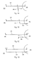
- Les
figures 1A à 1D illustrent de façon schématique quatre modes de réalisation de l'invention, - La
figure 2 détaille le mode de réalisation de lafigure 1A et comporte une vue agrandie d'une portion du dispositif, - La
figure 3 détaille le mode de réalisation de lafigure 1D , - La
figure 4 illustre en coupe transversale un mode de fixation d'un cordon sur un capuchon. - L'invention vise à fournir un dispositif pour fermer une ouverture de boîtier optique 400 de véhicule, en particulier de véhicule automobile. Ledit dispositif comprend un capuchon 300 et un moyen pour assujettir le capuchon 300 sur le boitier 400 de manière à le rendre imperdable. Selon une variante avantageuse, l'invention permet en outre de détecter une première ouverture du capuchon. A cet effet, elle propose un moyen de liaison entre le capuchon et le boitier prenant la forme d'un élément souple ou articulé qualifié dans la suite d'assistant d'ouverture.
- Selon des modes de réalisation préférés, l'assistant d'ouverture comporte un premier 100 et un second cordons 200 reliés l'un à l'autre. Le premier cordon 100 a une première extrémité A et une seconde extrémité B. Le second cordon 200 a une première extrémité C et une seconde extrémité D. Le premier cordon 100 a pour fonction d'assujettir le capuchon 300 au boitier 400. Par convention, on considérera que le premier cordon est, en utilisation, fixé au capuchon par sa première extrémité A et au boitier par sa seconde extrémité B.
- Le second cordon 200 est relié au premier cordon 100. Par convention, on considérera qu'il lui est relié par sa seconde extrémité D. Il y a trois façons de relier le second cordon au premier cordon :
- La seconde extrémité D est reliée au premier cordon 100 en un point intermédiaire entre ses deux extrémités A, B,
- La seconde extrémité D est reliée au premier cordon 100 par sa première extrémité A,
- La seconde extrémité D est reliée au premier cordon 100 par sa seconde extrémité B.
- Le second cordon 200 a pour fonction de signaler une première ouverture du capuchon. Dans les modes de réalisation illustrés, cette première ouverture est signalée par le bris du second cordon. A cet effet il possède un point fragile 210 pouvant être situé à l'une de ses extrémités C, D ou en un point intermédiaire entre ses extrémités.
- Dans le premier mode de réalisation schématiquement illustré en
figure 1A , le second cordon 200 est relié par sa seconde extrémité D en un point intermédiaire entre la première extrémité A et la seconde extrémité B du premier cordon 100, et sa première extrémité C est fixée au boitier. Lorsque le capuchon est enlevé par rotation, ce mouvement provoque un déplacement de la première extrémité A du premier cordon 100, dans le sens horaire ou anti horaire, et une traction sur le premier cordon 100 ; cette traction est transmise au second cordon 200 et provoque sa rupture au point fragile 210. Le déplacement de la première extrémité A du premier cordon 100 et la traction exercée sur le premier cordon (et donc indirectement sur le second cordon) sont d'autant plus importants que cette première extrémité A est fixée en périphérie du capuchon 300. - Le deuxième mode de réalisation schématiquement illustré en
figure 1B est semblable au premier mode de réalisation, mais dans ce cas la première extrémité C du second cordon est fixée au capuchon 300. La traction lors de l'ouverture du capuchon s'exerce donc directement à la fois sur le premier et le second cordon. Dans ce mode de réalisation, il est avantageux que la première extrémité A du premier cordon soit fixée proche du centre du capuchon 300 et la première extrémité C du second cordon 200 soit fixée en périphérie du capuchon 300 pour obtenir une traction plus forte sur le second cordon que sur le premier cordon. - Dans le troisième mode de réalisation schématique illustré en
figure 1C , le second cordon 200 est relié par sa seconde extrémité D à la première extrémité A du premier cordon 100, donc également au capuchon 300, et sa première extrémité C est fixée au boitier 400. Comme pour le deuxième mode de réalisation, il est avantageux que la seconde extrémité D du second cordon 200 soit fixée en périphérie du capuchon 300 pour obtenir un grand déplacement et donc une traction forte sur le second cordon. - Dans le quatrième mode de réalisation schématique illustré en
figure 1D , le second cordon 200 est relié par sa seconde extrémité D à la seconde extrémité B du premier cordon 100, donc également au boitier 400, et sa première extrémité C est fixée au capuchon 300. Comme pour le second mode de réalisation, il est avantageux que la première extrémité C du second cordon 200 soit fixée en périphérie du capuchon 300 pour obtenir un plus grand déplacement et donc une traction plus forte sur le second cordon. - La
figure 2 illustre un mode de réalisation du schéma de lafigure 1A . Le capuchon 300 est de forme circulaire comportant une partie centrale 310 et se fixe sur le boitier 400 par rotation. L'assistant d'ouverture est du type en Y, il est formé : - d'un premier cordon 100 dont la première extrémité A est fixée sur le capuchon et la seconde extrémité B est fixée sur le boitier ; tel que représenté sur la
figure 2 , la première extrémité A est fixée à proximité de la partie centrale 310 du capuchon, mais il pourrait être fixé à la périphérie du capuchon, - d'un second cordon 200 comportant une première extrémité C fixée sur le boitier et d'une seconde extrémité D reliée au premier cordon 100, entre sa première extrémité A et sa seconde extrémité B, environ à mi-distance des première et seconde extrémité du premier cordon.
- Les moyens de fixation des cordons sur le boitier ou le capuchon seront décrits plus loin.
- Le second cordon 200 est plus court que le premier cordon 100, environ cinq fois plus court tel que représenté sur la
figure 2 . - Comme il est visible sur la vue agrandie, le second cordon 200 comporte une partie frangible 210 consistant en un rétrécissement important du diamètre de ce cordon, entre ses première et seconde extrémité C, D. De façon alternative (non représentée), cette partie frangible pourrait être située au niveau de sa première C ou de sa seconde extrémité D.
- Le mouvement d'ouverture du capuchon 300 dans le sens de la flèche F provoque un déplacement de la première extrémité A du premier cordon et le met en tension ; par voie de conséquence, le second cordon 200 est également mis en tension et ultimement ce mouvement d'ouverture du capuchon provoque la rupture du second cordon à son point frangible 210. Cette mise en tension du premier 100 et du second cordon 200 sera d'autant plus importante que la première extrémité A du premier cordon 100 sera fixée proche de la périphérie du capuchon.
- L'assistant d'ouverture est par exemple réalisé en matériau plastique, ledit matériau présentant une certaine élasticité donnant aux cordons la souplesse nécessaire à la manipulation du capuchon tout en autorisant la rupture du point frangible, sous tension.
- Après ouverture, le capuchon 300 reste assujetti au boitier 400 par le premier cordon 100 et le second cordon 200, témoin de première ouverture, est rompu.
- La
figure 3 illustre un autre mode de réalisation de l'invention, correspondant au schéma de lafigure 1D . - Le premier cordon 100 est identique à celui de la
figure 2 . Le second cordon 200 en revanche comporte une première extrémité C fixée en bordure du capuchon 300 et une seconde extrémité D qui est commune avec la seconde extrémité B du premier cordon 100, toutes les deux étant fixées au boitier 400. Comme précédemment, le second cordon 200 comporte une partie frangible 210 entre sa première C et sa seconde extrémité D. - Le mouvement d'ouverture du capuchon 300 dans le sens de la flèche F provoque un déplacement de la première extrémité C du second cordon 200 et le met en tension ; ultimement ce mouvement d'ouverture du capuchon provoque la rupture du second cordon à son point frangible 210. Cette mise en tension du second cordon 200 sera d'autant plus importante que la première extrémité C du second cordon 200 sera fixée proche de la périphérie du capuchon.
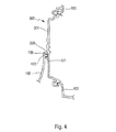
- Comme illustré à la
figure 4 , la capuchon 300 est avantageusement fixé de façon étanche au boitier 400. Ce dernier accueille intérieurement différents éléments optiques, non représentés, tel qu'une ou plusieurs sources lumineuses, des réflecteurs et/ou guide de lumière, ou autres. - La
figure 4 illustre également des moyens de fixation d'un cordon 150, pouvant être le premier 100 ou le second cordon 200, sur le capuchon 300. Ces moyens de fixation comportent d'une part une cavité 320 ménagée sur la face externe 301 du capuchon 300 et d'autre part une excroissance 120 à l'extrémité du cordon 150, excroissance qui s'étend de préférence, comme illustré enfigure 4 , orthogonalement à un axe longitudinal du cordon 150. A l'opposé de l'excroissance 120 par rapport à cet axe longitudinal s'étend un aplatissement 130 du cordon. De façon alternative, la cavité pourrait se trouver à l'extrémité du cordon et l'excroissance sur le capuchon. - Les formes de l'excroissance 120 et de la cavité 320 sont prévues pour coopérer en vue d'obtenir la fixation du cordon sur le capuchon par simple pression sur l'aplatissement 130, l'excroissance 120 pénétrant dans la cavité 320 avec friction. Pour favoriser le bon assemblage de l'excroissance dans la cavité, l'excroissance peut comporter sur sa surface une série de crans 121 par exemple annulaires, qui peuvent coopérer avec des crans homologues (non représentés) prévus sur la surface interne de la cavité 320.
- Bien entendu, les mêmes moyens de fixation peuvent être utilisés pour la fixation du cordon sur le boitier.
- La vue agrandie de la
figure 2 illustre d'autres moyens de fixation du cordon. Dans ce mode de réalisation, l'extrémité C du second cordon 200 comporte deux barbules 140 formant harpon, et un arceau 330 s'étend à partir de la surface du boitier 400. La fixation s'obtient simplement en faisant pénétrer l'extrémité du cordon en forme de harpon dans l'arceau 330. Les barbules 140 s'écartent et rendent difficile le retour en arrière. - Bien entendu, les mêmes moyens de fixation peuvent être utilisés pour la fixation d'un cordon sur le capuchon.
- La description qui précède n'est pas limitative. Ainsi, notamment, l'assistant d'ouverture pourra être prévu pour être fixé par vissage, les extrémités A, B et C du cordon comportant alors des passages de vis.
Claims (16)
- Dispositif pour fermer une ouverture de boitier optique (400) de véhicule, le dispositif comportant un capuchon (300), ledit capuchon (300) étant configuré pour fermer l'ouverture grâce à un mouvement réversible, caractérisé en ce qu'il comporte en outre un moyen de liaison souple ou articulé fixé au capuchon (300) et prévu pour être fixé au boitier (400), de sorte que, après ouverture, ledit capuchon (300) reste assujetti au boitier (400) par ledit moyen de liaison.
- Dispositif selon la revendication 1,
caractérisé en ce que le moyen de liaison comprend un premier cordon (100) souple comprenant deux extrémités, une première extrémité (A) comportant des moyens de fixation au capuchon (300) et une seconde extrémité (B) comportant des moyens de fixation (120) au boitier (400). - Dispositif selon la revendication 2,
caractérisé en ce qu'il comporte en outre un moyen de détection d'une première ouverture du capuchon (300). - Dispositif selon la revendication 3,
caractérisé en ce que le moyen de détection d'une première ouverture comprend un second cordon (200) souple comprenant deux extrémités, une première extrémité (C) comportant des moyens de fixation soit au capuchon (300) soit au boitier (400) et une seconde extrémité (D) reliée au premier cordon (100), et en ce que ledit second cordon (200) comprend une partie (210) qui change d'aspect de façon irréversible sous l'effet d'une traction, de sorte que le mouvement du capuchon (300) en vue de libérer l'ouverture provoque une traction sur ledit le second cordon (200) et donc son changement d'aspect. - Dispositif selon la revendication 4,
caractérisé en ce que la première extrémité (C) du second cordon (200) comporte des moyens de fixation au boitier (400) et la seconde extrémité (D) du second cordon (200) est reliée à un point du premier cordon (100) intermédiaire entre sa première (A) et sa seconde (B) extrémité. - Dispositif selon la revendication 4,
caractérisé en ce que la première extrémité (C) du second cordon (200) comporte des moyens de fixation au capuchon (300) et la seconde extrémité (D) du second cordon (200) est reliée à un point du premier cordon (100) intermédiaire entre sa première (A) et sa seconde (B) extrémité. - Dispositif selon la revendication 4,
caractérisé en ce que la première extrémité (C) du second cordon (200) comporte des moyens de fixation au capuchon (300) et la seconde extrémité (D) du second cordon (200) est reliée à la première extrémité (A) du premier cordon (100). - Dispositif selon la revendication 4,
caractérisé en ce que la première extrémité (C) du second cordon (200) comporte des moyens de fixation au boitier (400) et la seconde extrémité (D) du second cordon (200) est reliée à la seconde extrémité (B) du premier cordon (100). - Dispositif selon l'une des revendications 4 à 8,
caractérisé en ce que la partie (210) qui change d'aspect de façon irréversible est une partie du second cordon (200) frangible ou une partie apte à changer de couleur. - Dispositif selon la revendication 9,
caractérisé en ce que la partie (210) du second cordon qui change d'aspect de façon irréversible est l'une des parties suivantes : la première extrémité (C), la seconde extrémité (D), une partie comprise entre la première extrémité et la seconde extrémité. - Dispositif selon l'une des revendications 2 à 10,
caractérisé en ce que le capuchon (300) comporte des moyens de fixation (320) aptes à coopérer avec les moyens de fixation (120) du premier (100) et/ou du second (200) cordon pour obtenir la fixation d'une extrémité du ou des cordons sur le capuchon (300) par simple pression. - Dispositif selon la revendication 11,
caractérisé en ce que les moyens de fixation (320) du capuchon (300) aptes à coopérer avec les moyens de fixation (120) du premier (100) ou du second (200) cordon sont situés à proximité de la périphérie du capuchon (300). - Boitier optique pour véhicule comportant une ouverture et un dispositif selon l'une des revendications précédentes.
- Boitier selon la revendication 13 en ce qu'elle dépend de l'une quelconque des revendications 3 à 10,
caractérisé en ce que ledit boitier (400) comporte des moyens aptes à coopérer avec une extrémité du premier et/ou du second cordon pour obtenir la fixation d'une extrémité du ou des cordons sur le boitier par simple pression. - Cordon souple en forme de Y, comportant un moyen de fixation à l'extrémité (A, B, C) de chacune de ses branches, l'une des branches du Y comportant une partie (210) apte à changer d'aspect de façon irréversible sous l'effet d'une traction.
- Cordon souple linéaire, comportant un premier moyen de fixation à sa première extrémité (A ou B), un deuxième moyen de fixation à sa deuxième extrémité (C) et un troisième moyen de fixation en un point intermédiaire (D) entre sa première et sa deuxième extrémité, le cordon comportant une partie apte à changer d'aspect de façon irréversible sous l'effet d'une traction.
Applications Claiming Priority (1)
| Application Number | Priority Date | Filing Date | Title |
|---|---|---|---|
| FR1557429A FR3039474B1 (fr) | 2015-07-31 | 2015-07-31 | Dispositif pour fermer une ouverture de boitier optique de vehicule, boitier optique equipe d'un tel dispositif et cordon pour ledit dispositif |
Publications (3)
| Publication Number | Publication Date |
|---|---|
| EP3124326A2 true EP3124326A2 (fr) | 2017-02-01 |
| EP3124326A3 EP3124326A3 (fr) | 2017-04-05 |
| EP3124326B1 EP3124326B1 (fr) | 2019-06-12 |
Family
ID=54291480
Family Applications (1)
| Application Number | Title | Priority Date | Filing Date |
|---|---|---|---|
| EP16181764.8A Active EP3124326B1 (fr) | 2015-07-31 | 2016-07-28 | Dispositif pour fermer une ouverture de boîtier optique de véhicule, boîtier optique équipé d'un tel dispositif et cordon pour ledit dispositif |
Country Status (4)
| Country | Link |
|---|---|
| US (1) | US11092315B2 (fr) |
| EP (1) | EP3124326B1 (fr) |
| CN (1) | CN106402769B (fr) |
| FR (1) | FR3039474B1 (fr) |
Citations (1)
| Publication number | Priority date | Publication date | Assignee | Title |
|---|---|---|---|---|
| DE102008032278A1 (de) | 2007-07-30 | 2009-02-05 | Zizala Lichtsysteme Gmbh | Deckel zum Verschließen einer Öffnung eines Gehäuses eines Fahrzeugscheinwerfers |
Family Cites Families (21)
| Publication number | Priority date | Publication date | Assignee | Title |
|---|---|---|---|---|
| US1391361A (en) * | 1920-03-08 | 1921-09-20 | Walter L Beach | Exhibitor for signals |
| US3981053A (en) * | 1975-10-08 | 1976-09-21 | Dupage Manufacturing Company | Two-part worm drive clamp with variable length band-forming part |
| IT210491Z2 (it) * | 1987-02-24 | 1988-12-30 | Carello Spa | Proiettore per veicoli |
| JP2768870B2 (ja) * | 1991-08-05 | 1998-06-25 | 株式会社小糸製作所 | バラスト回路と点灯回路間のコード接続構造 |
| FR2711213B1 (fr) * | 1993-10-12 | 1996-01-05 | Valeo Vision | Boîtier, ensemble de capots et projecteur pour un dispositif d'éclairage ou de signalisation de véhicule automobile. |
| FR2738802B1 (fr) * | 1995-09-14 | 1997-10-24 | Pechiney Emballage Alimentaire | Dispositif de bouchage anti-fraude |
| JPH09298001A (ja) * | 1996-04-30 | 1997-11-18 | Koito Mfg Co Ltd | 車輌用前照灯 |
| CN2315068Y (zh) | 1997-07-11 | 1999-04-21 | 杨洪刚 | 断线防伪瓶 |
| JP2000251511A (ja) * | 1999-03-03 | 2000-09-14 | Koito Mfg Co Ltd | 車両用灯具 |
| JP2001236805A (ja) * | 2000-02-25 | 2001-08-31 | Matsushita Electric Works Ltd | 照明装置 |
| JP2002170407A (ja) * | 2000-12-01 | 2002-06-14 | Koito Mfg Co Ltd | 車両用前照灯 |
| US7448444B2 (en) * | 2002-04-10 | 2008-11-11 | Thomson Michael A | Tubing saver rotator and method for using same |
| JP4240478B2 (ja) * | 2004-03-31 | 2009-03-18 | 株式会社パイオラックス | 車両用収納装置 |
| FR2916173A1 (fr) * | 2007-05-15 | 2008-11-21 | Valeo Vision Sa | Bouchon d'obturation de dispositif d'eclairage et/ou de signalisation. |
| KR20100005809A (ko) | 2008-07-08 | 2010-01-18 | 강형석 | 변기의 병원균살균장치 |
| KR101074915B1 (ko) * | 2008-11-24 | 2011-10-18 | 한국지엠 주식회사 | 자동차용 전조등 |
| JP2010219019A (ja) * | 2009-02-20 | 2010-09-30 | Koito Mfg Co Ltd | バックカバー及びバックカバーの組立方法 |
| CN202838382U (zh) * | 2012-09-20 | 2013-03-27 | 上海紫檀鼎电子科技有限公司 | 一种扎带式线材防盗有源rfid标签 |
| US20150197179A1 (en) * | 2014-01-16 | 2015-07-16 | Valeo Lighting Systems North America, Llc | Clutch for adjuster in headlamps |
| TWM506831U (zh) * | 2015-03-31 | 2015-08-11 | Seal King Ind Co Ltd | 防偽膠帶之拆緘顯示結構 |
| FR3037636A1 (fr) * | 2015-06-22 | 2016-12-23 | Valeo Vision | Enveloppe de protection polymerique pour faisceaux electriques dans un dispositif lumineux de vehicule automobile |
-
2015
- 2015-07-31 FR FR1557429A patent/FR3039474B1/fr active Active
-
2016
- 2016-07-28 EP EP16181764.8A patent/EP3124326B1/fr active Active
- 2016-07-29 US US15/223,516 patent/US11092315B2/en active Active
- 2016-08-01 CN CN201610620265.0A patent/CN106402769B/zh active Active
Patent Citations (1)
| Publication number | Priority date | Publication date | Assignee | Title |
|---|---|---|---|---|
| DE102008032278A1 (de) | 2007-07-30 | 2009-02-05 | Zizala Lichtsysteme Gmbh | Deckel zum Verschließen einer Öffnung eines Gehäuses eines Fahrzeugscheinwerfers |
Also Published As
| Publication number | Publication date |
|---|---|
| FR3039474A1 (fr) | 2017-02-03 |
| US11092315B2 (en) | 2021-08-17 |
| EP3124326A3 (fr) | 2017-04-05 |
| FR3039474B1 (fr) | 2021-02-19 |
| CN106402769B (zh) | 2021-10-19 |
| CN106402769A (zh) | 2017-02-15 |
| EP3124326B1 (fr) | 2019-06-12 |
| US20170051891A1 (en) | 2017-02-23 |
Similar Documents
| Publication | Publication Date | Title |
|---|---|---|
| EP1178175B1 (fr) | Système de positionnement et d'assemblage d'une vitre sur un lève-vitre | |
| FR2900212A1 (fr) | Plaque de maillon pour une chaine | |
| FR2725531A1 (fr) | Dispositif d'embrayage pour barillet d'objectif zoom | |
| FR2555695A1 (fr) | Derailleur avant comportant un element de protection ou capuchon pour le ressort de rappel | |
| CA2539926C (fr) | Collier de maintien | |
| FR2742720A1 (fr) | Dispositif d'eclairage ou de signalisation lumineuse amovible, notamment pour deux roues | |
| WO2008101780A1 (fr) | Dispositif a rideau enroulable | |
| FR3028215A1 (fr) | Dispositif de bridage d’un boitier de capteur de pression et de temperature sur une jante de vehicule et boitier adapte | |
| EP3124326B1 (fr) | Dispositif pour fermer une ouverture de boîtier optique de véhicule, boîtier optique équipé d'un tel dispositif et cordon pour ledit dispositif | |
| FR2836354A1 (fr) | Dispositif de protection, de presentation et d'utilisation a des fins d'ornementation courante d'une piece de monnaie | |
| FR2936829A1 (fr) | Dispositif de verrouillage. | |
| WO1994016654A1 (fr) | Paire de lunettes modulable | |
| FR3013524A1 (fr) | Fourreau a embout rotatif pour faisceau electrique apte a etre monte entre le chassis et un ouvrant d'un vehicule automobile | |
| EP0536006A1 (fr) | Témoin d'usure pour garniture de friction | |
| CH691132A5 (fr) | Dispositif de trasmission pour la manoeuvre d'un store. | |
| FR3024343A1 (fr) | Systeme de protection pour dispositif de communication mobile et procede d'installation de ce systeme de protection | |
| EP0531274A1 (fr) | Dispositif de fixation d'une toile sur un support d'enroulement | |
| EP3169559B1 (fr) | Platine d'essuie-glace, notamment pour véhicules automobiles | |
| FR2740765A1 (fr) | Mecanisme de traction a cabestan et outillages ainsi equipes | |
| FR2792975A1 (fr) | Collier articule | |
| EP3290629B1 (fr) | Enrouleur pour sangle, cordon ou analogue | |
| FR2679342A1 (fr) | Dispositif appui-face pour systeme optique. | |
| FR2478176A1 (fr) | Dispositif de blocage en position levee d'une piece mobile d'un vehicule automobile | |
| FR2967382A1 (fr) | Dispositif de protection amovible des flancs d'un vehicule automobile | |
| WO2008089891A1 (fr) | Dispositif de positionnement d'un element sur un câble |
Legal Events
| Date | Code | Title | Description |
|---|---|---|---|
| PUAI | Public reference made under article 153(3) epc to a published international application that has entered the european phase |
Free format text: ORIGINAL CODE: 0009012 |
|
| STAA | Information on the status of an ep patent application or granted ep patent |
Free format text: STATUS: THE APPLICATION HAS BEEN PUBLISHED |
|
| AK | Designated contracting states |
Kind code of ref document: A2 Designated state(s): AL AT BE BG CH CY CZ DE DK EE ES FI FR GB GR HR HU IE IS IT LI LT LU LV MC MK MT NL NO PL PT RO RS SE SI SK SM TR |
|
| AX | Request for extension of the european patent |
Extension state: BA ME |
|
| PUAL | Search report despatched |
Free format text: ORIGINAL CODE: 0009013 |
|
| AK | Designated contracting states |
Kind code of ref document: A3 Designated state(s): AL AT BE BG CH CY CZ DE DK EE ES FI FR GB GR HR HU IE IS IT LI LT LU LV MC MK MT NL NO PL PT RO RS SE SI SK SM TR |
|
| AX | Request for extension of the european patent |
Extension state: BA ME |
|
| RIC1 | Information provided on ipc code assigned before grant |
Ipc: B60Q 1/00 20060101AFI20170302BHEP |
|
| STAA | Information on the status of an ep patent application or granted ep patent |
Free format text: STATUS: REQUEST FOR EXAMINATION WAS MADE |
|
| 17P | Request for examination filed |
Effective date: 20171003 |
|
| RBV | Designated contracting states (corrected) |
Designated state(s): AL AT BE BG CH CY CZ DE DK EE ES FI FR GB GR HR HU IE IS IT LI LT LU LV MC MK MT NL NO PL PT RO RS SE SI SK SM TR |
|
| GRAP | Despatch of communication of intention to grant a patent |
Free format text: ORIGINAL CODE: EPIDOSNIGR1 |
|
| STAA | Information on the status of an ep patent application or granted ep patent |
Free format text: STATUS: GRANT OF PATENT IS INTENDED |
|
| INTG | Intention to grant announced |
Effective date: 20190123 |
|
| RIN1 | Information on inventor provided before grant (corrected) |
Inventor name: MADORRAN TIL, GONZALO Inventor name: CABANNE, DAMIEN Inventor name: RUBIA MENA, JUAN-ANTONIO Inventor name: FERNANDEZ, RICARDO Inventor name: MORENO, JUAN-FRANCISCO Inventor name: RUIZ, FRANCISCO Inventor name: PASTOR, RAMON |
|
| GRAS | Grant fee paid |
Free format text: ORIGINAL CODE: EPIDOSNIGR3 |
|
| GRAA | (expected) grant |
Free format text: ORIGINAL CODE: 0009210 |
|
| STAA | Information on the status of an ep patent application or granted ep patent |
Free format text: STATUS: THE PATENT HAS BEEN GRANTED |
|
| AK | Designated contracting states |
Kind code of ref document: B1 Designated state(s): AL AT BE BG CH CY CZ DE DK EE ES FI FR GB GR HR HU IE IS IT LI LT LU LV MC MK MT NL NO PL PT RO RS SE SI SK SM TR |
|
| REG | Reference to a national code |
Ref country code: GB Ref legal event code: FG4D Free format text: NOT ENGLISH |
|
| REG | Reference to a national code |
Ref country code: CH Ref legal event code: EP |
|
| REG | Reference to a national code |
Ref country code: AT Ref legal event code: REF Ref document number: 1142136 Country of ref document: AT Kind code of ref document: T Effective date: 20190615 |
|
| REG | Reference to a national code |
Ref country code: IE Ref legal event code: FG4D Free format text: LANGUAGE OF EP DOCUMENT: FRENCH |
|
| REG | Reference to a national code |
Ref country code: DE Ref legal event code: R096 Ref document number: 602016015061 Country of ref document: DE |
|
| REG | Reference to a national code |
Ref country code: NL Ref legal event code: MP Effective date: 20190612 |
|
| REG | Reference to a national code |
Ref country code: LT Ref legal event code: MG4D |
|
| PG25 | Lapsed in a contracting state [announced via postgrant information from national office to epo] |
Ref country code: LT Free format text: LAPSE BECAUSE OF FAILURE TO SUBMIT A TRANSLATION OF THE DESCRIPTION OR TO PAY THE FEE WITHIN THE PRESCRIBED TIME-LIMIT Effective date: 20190612 Ref country code: FI Free format text: LAPSE BECAUSE OF FAILURE TO SUBMIT A TRANSLATION OF THE DESCRIPTION OR TO PAY THE FEE WITHIN THE PRESCRIBED TIME-LIMIT Effective date: 20190612 Ref country code: SE Free format text: LAPSE BECAUSE OF FAILURE TO SUBMIT A TRANSLATION OF THE DESCRIPTION OR TO PAY THE FEE WITHIN THE PRESCRIBED TIME-LIMIT Effective date: 20190612 Ref country code: NO Free format text: LAPSE BECAUSE OF FAILURE TO SUBMIT A TRANSLATION OF THE DESCRIPTION OR TO PAY THE FEE WITHIN THE PRESCRIBED TIME-LIMIT Effective date: 20190912 Ref country code: HR Free format text: LAPSE BECAUSE OF FAILURE TO SUBMIT A TRANSLATION OF THE DESCRIPTION OR TO PAY THE FEE WITHIN THE PRESCRIBED TIME-LIMIT Effective date: 20190612 Ref country code: AL Free format text: LAPSE BECAUSE OF FAILURE TO SUBMIT A TRANSLATION OF THE DESCRIPTION OR TO PAY THE FEE WITHIN THE PRESCRIBED TIME-LIMIT Effective date: 20190612 |
|
| PG25 | Lapsed in a contracting state [announced via postgrant information from national office to epo] |
Ref country code: BG Free format text: LAPSE BECAUSE OF FAILURE TO SUBMIT A TRANSLATION OF THE DESCRIPTION OR TO PAY THE FEE WITHIN THE PRESCRIBED TIME-LIMIT Effective date: 20190912 Ref country code: GR Free format text: LAPSE BECAUSE OF FAILURE TO SUBMIT A TRANSLATION OF THE DESCRIPTION OR TO PAY THE FEE WITHIN THE PRESCRIBED TIME-LIMIT Effective date: 20190913 Ref country code: RS Free format text: LAPSE BECAUSE OF FAILURE TO SUBMIT A TRANSLATION OF THE DESCRIPTION OR TO PAY THE FEE WITHIN THE PRESCRIBED TIME-LIMIT Effective date: 20190612 Ref country code: LV Free format text: LAPSE BECAUSE OF FAILURE TO SUBMIT A TRANSLATION OF THE DESCRIPTION OR TO PAY THE FEE WITHIN THE PRESCRIBED TIME-LIMIT Effective date: 20190612 |
|
| REG | Reference to a national code |
Ref country code: AT Ref legal event code: MK05 Ref document number: 1142136 Country of ref document: AT Kind code of ref document: T Effective date: 20190612 |
|
| PG25 | Lapsed in a contracting state [announced via postgrant information from national office to epo] |
Ref country code: EE Free format text: LAPSE BECAUSE OF FAILURE TO SUBMIT A TRANSLATION OF THE DESCRIPTION OR TO PAY THE FEE WITHIN THE PRESCRIBED TIME-LIMIT Effective date: 20190612 Ref country code: SK Free format text: LAPSE BECAUSE OF FAILURE TO SUBMIT A TRANSLATION OF THE DESCRIPTION OR TO PAY THE FEE WITHIN THE PRESCRIBED TIME-LIMIT Effective date: 20190612 Ref country code: PT Free format text: LAPSE BECAUSE OF FAILURE TO SUBMIT A TRANSLATION OF THE DESCRIPTION OR TO PAY THE FEE WITHIN THE PRESCRIBED TIME-LIMIT Effective date: 20191014 Ref country code: AT Free format text: LAPSE BECAUSE OF FAILURE TO SUBMIT A TRANSLATION OF THE DESCRIPTION OR TO PAY THE FEE WITHIN THE PRESCRIBED TIME-LIMIT Effective date: 20190612 Ref country code: NL Free format text: LAPSE BECAUSE OF FAILURE TO SUBMIT A TRANSLATION OF THE DESCRIPTION OR TO PAY THE FEE WITHIN THE PRESCRIBED TIME-LIMIT Effective date: 20190612 Ref country code: CZ Free format text: LAPSE BECAUSE OF FAILURE TO SUBMIT A TRANSLATION OF THE DESCRIPTION OR TO PAY THE FEE WITHIN THE PRESCRIBED TIME-LIMIT Effective date: 20190612 Ref country code: RO Free format text: LAPSE BECAUSE OF FAILURE TO SUBMIT A TRANSLATION OF THE DESCRIPTION OR TO PAY THE FEE WITHIN THE PRESCRIBED TIME-LIMIT Effective date: 20190612 |
|
| PG25 | Lapsed in a contracting state [announced via postgrant information from national office to epo] |
Ref country code: SM Free format text: LAPSE BECAUSE OF FAILURE TO SUBMIT A TRANSLATION OF THE DESCRIPTION OR TO PAY THE FEE WITHIN THE PRESCRIBED TIME-LIMIT Effective date: 20190612 Ref country code: ES Free format text: LAPSE BECAUSE OF FAILURE TO SUBMIT A TRANSLATION OF THE DESCRIPTION OR TO PAY THE FEE WITHIN THE PRESCRIBED TIME-LIMIT Effective date: 20190612 Ref country code: IT Free format text: LAPSE BECAUSE OF FAILURE TO SUBMIT A TRANSLATION OF THE DESCRIPTION OR TO PAY THE FEE WITHIN THE PRESCRIBED TIME-LIMIT Effective date: 20190612 Ref country code: IS Free format text: LAPSE BECAUSE OF FAILURE TO SUBMIT A TRANSLATION OF THE DESCRIPTION OR TO PAY THE FEE WITHIN THE PRESCRIBED TIME-LIMIT Effective date: 20191012 |
|
| REG | Reference to a national code |
Ref country code: CH Ref legal event code: PL |
|
| REG | Reference to a national code |
Ref country code: DE Ref legal event code: R097 Ref document number: 602016015061 Country of ref document: DE |
|
| PG25 | Lapsed in a contracting state [announced via postgrant information from national office to epo] |
Ref country code: MC Free format text: LAPSE BECAUSE OF FAILURE TO SUBMIT A TRANSLATION OF THE DESCRIPTION OR TO PAY THE FEE WITHIN THE PRESCRIBED TIME-LIMIT Effective date: 20190612 Ref country code: TR Free format text: LAPSE BECAUSE OF FAILURE TO SUBMIT A TRANSLATION OF THE DESCRIPTION OR TO PAY THE FEE WITHIN THE PRESCRIBED TIME-LIMIT Effective date: 20190612 |
|
| REG | Reference to a national code |
Ref country code: BE Ref legal event code: MM Effective date: 20190731 |
|
| PLBE | No opposition filed within time limit |
Free format text: ORIGINAL CODE: 0009261 |
|
| STAA | Information on the status of an ep patent application or granted ep patent |
Free format text: STATUS: NO OPPOSITION FILED WITHIN TIME LIMIT |
|
| PG25 | Lapsed in a contracting state [announced via postgrant information from national office to epo] |
Ref country code: PL Free format text: LAPSE BECAUSE OF FAILURE TO SUBMIT A TRANSLATION OF THE DESCRIPTION OR TO PAY THE FEE WITHIN THE PRESCRIBED TIME-LIMIT Effective date: 20190612 Ref country code: DK Free format text: LAPSE BECAUSE OF FAILURE TO SUBMIT A TRANSLATION OF THE DESCRIPTION OR TO PAY THE FEE WITHIN THE PRESCRIBED TIME-LIMIT Effective date: 20190612 |
|
| 26N | No opposition filed |
Effective date: 20200313 |
|
| PG25 | Lapsed in a contracting state [announced via postgrant information from national office to epo] |
Ref country code: IS Free format text: LAPSE BECAUSE OF FAILURE TO SUBMIT A TRANSLATION OF THE DESCRIPTION OR TO PAY THE FEE WITHIN THE PRESCRIBED TIME-LIMIT Effective date: 20200224 Ref country code: CH Free format text: LAPSE BECAUSE OF NON-PAYMENT OF DUE FEES Effective date: 20190731 Ref country code: LU Free format text: LAPSE BECAUSE OF NON-PAYMENT OF DUE FEES Effective date: 20190728 Ref country code: LI Free format text: LAPSE BECAUSE OF NON-PAYMENT OF DUE FEES Effective date: 20190731 Ref country code: BE Free format text: LAPSE BECAUSE OF NON-PAYMENT OF DUE FEES Effective date: 20190731 Ref country code: SI Free format text: LAPSE BECAUSE OF FAILURE TO SUBMIT A TRANSLATION OF THE DESCRIPTION OR TO PAY THE FEE WITHIN THE PRESCRIBED TIME-LIMIT Effective date: 20190612 |
|
| PG2D | Information on lapse in contracting state deleted |
Ref country code: IS |
|
| PG25 | Lapsed in a contracting state [announced via postgrant information from national office to epo] |
Ref country code: IE Free format text: LAPSE BECAUSE OF NON-PAYMENT OF DUE FEES Effective date: 20190728 |
|
| GBPC | Gb: european patent ceased through non-payment of renewal fee |
Effective date: 20200728 |
|
| PG25 | Lapsed in a contracting state [announced via postgrant information from national office to epo] |
Ref country code: GB Free format text: LAPSE BECAUSE OF NON-PAYMENT OF DUE FEES Effective date: 20200728 |
|
| PG25 | Lapsed in a contracting state [announced via postgrant information from national office to epo] |
Ref country code: CY Free format text: LAPSE BECAUSE OF FAILURE TO SUBMIT A TRANSLATION OF THE DESCRIPTION OR TO PAY THE FEE WITHIN THE PRESCRIBED TIME-LIMIT Effective date: 20190612 |
|
| PG25 | Lapsed in a contracting state [announced via postgrant information from national office to epo] |
Ref country code: MT Free format text: LAPSE BECAUSE OF FAILURE TO SUBMIT A TRANSLATION OF THE DESCRIPTION OR TO PAY THE FEE WITHIN THE PRESCRIBED TIME-LIMIT Effective date: 20190612 Ref country code: HU Free format text: LAPSE BECAUSE OF FAILURE TO SUBMIT A TRANSLATION OF THE DESCRIPTION OR TO PAY THE FEE WITHIN THE PRESCRIBED TIME-LIMIT; INVALID AB INITIO Effective date: 20160728 |
|
| PG25 | Lapsed in a contracting state [announced via postgrant information from national office to epo] |
Ref country code: MK Free format text: LAPSE BECAUSE OF FAILURE TO SUBMIT A TRANSLATION OF THE DESCRIPTION OR TO PAY THE FEE WITHIN THE PRESCRIBED TIME-LIMIT Effective date: 20190612 |
|
| P01 | Opt-out of the competence of the unified patent court (upc) registered |
Effective date: 20230629 |
|
| PGFP | Annual fee paid to national office [announced via postgrant information from national office to epo] |
Ref country code: DE Payment date: 20250711 Year of fee payment: 10 |
|
| PGFP | Annual fee paid to national office [announced via postgrant information from national office to epo] |
Ref country code: FR Payment date: 20250730 Year of fee payment: 10 |