EP3124256A1 - Behandlungszielmodifikationsvorrichtung, behandlungszielmodifikationssystem, bilderzeugungssystem und bilderzeugungsverfahren - Google Patents
Behandlungszielmodifikationsvorrichtung, behandlungszielmodifikationssystem, bilderzeugungssystem und bilderzeugungsverfahren Download PDFInfo
- Publication number
- EP3124256A1 EP3124256A1 EP16175972.5A EP16175972A EP3124256A1 EP 3124256 A1 EP3124256 A1 EP 3124256A1 EP 16175972 A EP16175972 A EP 16175972A EP 3124256 A1 EP3124256 A1 EP 3124256A1
- Authority
- EP
- European Patent Office
- Prior art keywords
- treatment
- target
- hydrophilization
- plasma
- reflectance spectrum
- Prior art date
- Legal status (The legal status is an assumption and is not a legal conclusion. Google has not performed a legal analysis and makes no representation as to the accuracy of the status listed.)
- Granted
Links
- 238000012986 modification Methods 0.000 title claims abstract description 28
- 230000004048 modification Effects 0.000 title claims abstract description 28
- 238000000034 method Methods 0.000 title claims description 59
- 238000000985 reflectance spectrum Methods 0.000 claims abstract description 44
- 238000005259 measurement Methods 0.000 claims abstract description 16
- 238000009826 distribution Methods 0.000 claims abstract description 12
- 238000009832 plasma treatment Methods 0.000 claims description 73
- 238000011156 evaluation Methods 0.000 claims description 7
- 238000003851 corona treatment Methods 0.000 claims description 5
- 238000012545 processing Methods 0.000 description 13
- 230000008569 process Effects 0.000 description 9
- 230000004888 barrier function Effects 0.000 description 8
- 238000010586 diagram Methods 0.000 description 8
- 230000008859 change Effects 0.000 description 6
- 239000010408 film Substances 0.000 description 5
- 238000002310 reflectometry Methods 0.000 description 5
- 238000012800 visualization Methods 0.000 description 5
- 238000006243 chemical reaction Methods 0.000 description 4
- 239000007789 gas Substances 0.000 description 4
- 239000002184 metal Substances 0.000 description 3
- 239000000615 nonconductor Substances 0.000 description 3
- 230000035945 sensitivity Effects 0.000 description 3
- XLYOFNOQVPJJNP-UHFFFAOYSA-N water Substances O XLYOFNOQVPJJNP-UHFFFAOYSA-N 0.000 description 3
- IJGRMHOSHXDMSA-UHFFFAOYSA-N Atomic nitrogen Chemical compound N#N IJGRMHOSHXDMSA-UHFFFAOYSA-N 0.000 description 2
- 230000015556 catabolic process Effects 0.000 description 2
- 239000000919 ceramic Substances 0.000 description 2
- 239000003086 colorant Substances 0.000 description 2
- 230000003247 decreasing effect Effects 0.000 description 2
- 230000002950 deficient Effects 0.000 description 2
- 238000006731 degradation reaction Methods 0.000 description 2
- 239000007850 fluorescent dye Substances 0.000 description 2
- 238000012805 post-processing Methods 0.000 description 2
- 239000002904 solvent Substances 0.000 description 2
- 238000001228 spectrum Methods 0.000 description 2
- CBENFWSGALASAD-UHFFFAOYSA-N Ozone Chemical compound [O-][O+]=O CBENFWSGALASAD-UHFFFAOYSA-N 0.000 description 1
- 239000004642 Polyimide Substances 0.000 description 1
- 230000008901 benefit Effects 0.000 description 1
- 239000011230 binding agent Substances 0.000 description 1
- 230000015572 biosynthetic process Effects 0.000 description 1
- 230000000740 bleeding effect Effects 0.000 description 1
- 229910052799 carbon Inorganic materials 0.000 description 1
- 239000003153 chemical reaction reagent Substances 0.000 description 1
- 238000004581 coalescence Methods 0.000 description 1
- 238000012937 correction Methods 0.000 description 1
- 230000007423 decrease Effects 0.000 description 1
- 230000005684 electric field Effects 0.000 description 1
- 230000002349 favourable effect Effects 0.000 description 1
- 125000000524 functional group Chemical group 0.000 description 1
- 229910052736 halogen Inorganic materials 0.000 description 1
- 150000002367 halogens Chemical class 0.000 description 1
- 238000009413 insulation Methods 0.000 description 1
- 239000007788 liquid Substances 0.000 description 1
- 238000004519 manufacturing process Methods 0.000 description 1
- 238000013507 mapping Methods 0.000 description 1
- 229910052757 nitrogen Inorganic materials 0.000 description 1
- 229910052760 oxygen Inorganic materials 0.000 description 1
- 239000001301 oxygen Substances 0.000 description 1
- 230000020477 pH reduction Effects 0.000 description 1
- 229920001721 polyimide Polymers 0.000 description 1
- 229920000642 polymer Polymers 0.000 description 1
- 230000009467 reduction Effects 0.000 description 1
- 229920005989 resin Polymers 0.000 description 1
- 239000011347 resin Substances 0.000 description 1
- 229910052710 silicon Inorganic materials 0.000 description 1
- 239000010703 silicon Substances 0.000 description 1
- 229920003002 synthetic resin Polymers 0.000 description 1
- 239000000057 synthetic resin Substances 0.000 description 1
- 238000012360 testing method Methods 0.000 description 1
- 239000010409 thin film Substances 0.000 description 1
- 238000012546 transfer Methods 0.000 description 1
- 238000011144 upstream manufacturing Methods 0.000 description 1
Images


Classifications
-
- B—PERFORMING OPERATIONS; TRANSPORTING
- B41—PRINTING; LINING MACHINES; TYPEWRITERS; STAMPS
- B41J—TYPEWRITERS; SELECTIVE PRINTING MECHANISMS, i.e. MECHANISMS PRINTING OTHERWISE THAN FROM A FORME; CORRECTION OF TYPOGRAPHICAL ERRORS
- B41J29/00—Details of, or accessories for, typewriters or selective printing mechanisms not otherwise provided for
- B41J29/38—Drives, motors, controls or automatic cut-off devices for the entire printing mechanism
- B41J29/393—Devices for controlling or analysing the entire machine ; Controlling or analysing mechanical parameters involving printing of test patterns
-
- B—PERFORMING OPERATIONS; TRANSPORTING
- B41—PRINTING; LINING MACHINES; TYPEWRITERS; STAMPS
- B41J—TYPEWRITERS; SELECTIVE PRINTING MECHANISMS, i.e. MECHANISMS PRINTING OTHERWISE THAN FROM A FORME; CORRECTION OF TYPOGRAPHICAL ERRORS
- B41J11/00—Devices or arrangements of selective printing mechanisms, e.g. ink-jet printers or thermal printers, for supporting or handling copy material in sheet or web form
- B41J11/0015—Devices or arrangements of selective printing mechanisms, e.g. ink-jet printers or thermal printers, for supporting or handling copy material in sheet or web form for treating before, during or after printing or for uniform coating or laminating the copy material before or after printing
-
- B—PERFORMING OPERATIONS; TRANSPORTING
- B05—SPRAYING OR ATOMISING IN GENERAL; APPLYING FLUENT MATERIALS TO SURFACES, IN GENERAL
- B05D—PROCESSES FOR APPLYING FLUENT MATERIALS TO SURFACES, IN GENERAL
- B05D3/00—Pretreatment of surfaces to which liquids or other fluent materials are to be applied; After-treatment of applied coatings, e.g. intermediate treating of an applied coating preparatory to subsequent applications of liquids or other fluent materials
- B05D3/14—Pretreatment of surfaces to which liquids or other fluent materials are to be applied; After-treatment of applied coatings, e.g. intermediate treating of an applied coating preparatory to subsequent applications of liquids or other fluent materials by electrical means
- B05D3/141—Plasma treatment
- B05D3/142—Pretreatment
-
- B—PERFORMING OPERATIONS; TRANSPORTING
- B41—PRINTING; LINING MACHINES; TYPEWRITERS; STAMPS
- B41J—TYPEWRITERS; SELECTIVE PRINTING MECHANISMS, i.e. MECHANISMS PRINTING OTHERWISE THAN FROM A FORME; CORRECTION OF TYPOGRAPHICAL ERRORS
- B41J2/00—Typewriters or selective printing mechanisms characterised by the printing or marking process for which they are designed
- B41J2/005—Typewriters or selective printing mechanisms characterised by the printing or marking process for which they are designed characterised by bringing liquid or particles selectively into contact with a printing material
- B41J2/01—Ink jet
- B41J2/07—Ink jet characterised by jet control
-
- B—PERFORMING OPERATIONS; TRANSPORTING
- B41—PRINTING; LINING MACHINES; TYPEWRITERS; STAMPS
- B41J—TYPEWRITERS; SELECTIVE PRINTING MECHANISMS, i.e. MECHANISMS PRINTING OTHERWISE THAN FROM A FORME; CORRECTION OF TYPOGRAPHICAL ERRORS
- B41J2/00—Typewriters or selective printing mechanisms characterised by the printing or marking process for which they are designed
- B41J2/005—Typewriters or selective printing mechanisms characterised by the printing or marking process for which they are designed characterised by bringing liquid or particles selectively into contact with a printing material
- B41J2/01—Ink jet
- B41J2/21—Ink jet for multi-colour printing
- B41J2/2132—Print quality control characterised by dot disposition, e.g. for reducing white stripes or banding
- B41J2/2146—Print quality control characterised by dot disposition, e.g. for reducing white stripes or banding for line print heads
-
- B—PERFORMING OPERATIONS; TRANSPORTING
- B41—PRINTING; LINING MACHINES; TYPEWRITERS; STAMPS
- B41J—TYPEWRITERS; SELECTIVE PRINTING MECHANISMS, i.e. MECHANISMS PRINTING OTHERWISE THAN FROM A FORME; CORRECTION OF TYPOGRAPHICAL ERRORS
- B41J3/00—Typewriters or selective printing or marking mechanisms characterised by the purpose for which they are constructed
- B41J3/44—Typewriters or selective printing mechanisms having dual functions or combined with, or coupled to, apparatus performing other functions
- B41J3/445—Printers integrated in other types of apparatus, e.g. printers integrated in cameras
-
- B—PERFORMING OPERATIONS; TRANSPORTING
- B41—PRINTING; LINING MACHINES; TYPEWRITERS; STAMPS
- B41M—PRINTING, DUPLICATING, MARKING, OR COPYING PROCESSES; COLOUR PRINTING
- B41M5/00—Duplicating or marking methods; Sheet materials for use therein
-
- B—PERFORMING OPERATIONS; TRANSPORTING
- B41—PRINTING; LINING MACHINES; TYPEWRITERS; STAMPS
- B41M—PRINTING, DUPLICATING, MARKING, OR COPYING PROCESSES; COLOUR PRINTING
- B41M5/00—Duplicating or marking methods; Sheet materials for use therein
- B41M5/0011—Pre-treatment or treatment during printing of the recording material, e.g. heating, irradiating
-
- H—ELECTRICITY
- H01—ELECTRIC ELEMENTS
- H01J—ELECTRIC DISCHARGE TUBES OR DISCHARGE LAMPS
- H01J37/00—Discharge tubes with provision for introducing objects or material to be exposed to the discharge, e.g. for the purpose of examination or processing thereof
- H01J37/32—Gas-filled discharge tubes
- H01J37/32009—Arrangements for generation of plasma specially adapted for examination or treatment of objects, e.g. plasma sources
- H01J37/32073—Corona discharge
-
- H—ELECTRICITY
- H01—ELECTRIC ELEMENTS
- H01J—ELECTRIC DISCHARGE TUBES OR DISCHARGE LAMPS
- H01J37/00—Discharge tubes with provision for introducing objects or material to be exposed to the discharge, e.g. for the purpose of examination or processing thereof
- H01J37/32—Gas-filled discharge tubes
- H01J37/32009—Arrangements for generation of plasma specially adapted for examination or treatment of objects, e.g. plasma sources
- H01J37/32348—Dielectric barrier discharge
-
- H—ELECTRICITY
- H01—ELECTRIC ELEMENTS
- H01J—ELECTRIC DISCHARGE TUBES OR DISCHARGE LAMPS
- H01J37/00—Discharge tubes with provision for introducing objects or material to be exposed to the discharge, e.g. for the purpose of examination or processing thereof
- H01J37/32—Gas-filled discharge tubes
- H01J37/32431—Constructional details of the reactor
- H01J37/32798—Further details of plasma apparatus not provided for in groups H01J37/3244 - H01J37/32788; special provisions for cleaning or maintenance of the apparatus
- H01J37/32889—Connection or combination with other apparatus
-
- H—ELECTRICITY
- H01—ELECTRIC ELEMENTS
- H01J—ELECTRIC DISCHARGE TUBES OR DISCHARGE LAMPS
- H01J37/00—Discharge tubes with provision for introducing objects or material to be exposed to the discharge, e.g. for the purpose of examination or processing thereof
- H01J37/32—Gas-filled discharge tubes
- H01J37/32917—Plasma diagnostics
- H01J37/32935—Monitoring and controlling tubes by information coming from the object and/or discharge
- H01J37/32972—Spectral analysis
-
- B—PERFORMING OPERATIONS; TRANSPORTING
- B41—PRINTING; LINING MACHINES; TYPEWRITERS; STAMPS
- B41J—TYPEWRITERS; SELECTIVE PRINTING MECHANISMS, i.e. MECHANISMS PRINTING OTHERWISE THAN FROM A FORME; CORRECTION OF TYPOGRAPHICAL ERRORS
- B41J2/00—Typewriters or selective printing mechanisms characterised by the printing or marking process for which they are designed
- B41J2/005—Typewriters or selective printing mechanisms characterised by the printing or marking process for which they are designed characterised by bringing liquid or particles selectively into contact with a printing material
- B41J2/01—Ink jet
- B41J2/21—Ink jet for multi-colour printing
- B41J2/2107—Ink jet for multi-colour printing characterised by the ink properties
- B41J2/2114—Ejecting specialized liquids, e.g. transparent or processing liquids
-
- B—PERFORMING OPERATIONS; TRANSPORTING
- B41—PRINTING; LINING MACHINES; TYPEWRITERS; STAMPS
- B41J—TYPEWRITERS; SELECTIVE PRINTING MECHANISMS, i.e. MECHANISMS PRINTING OTHERWISE THAN FROM A FORME; CORRECTION OF TYPOGRAPHICAL ERRORS
- B41J2202/00—Embodiments of or processes related to ink-jet or thermal heads
- B41J2202/01—Embodiments of or processes related to ink-jet heads
- B41J2202/21—Line printing
-
- H—ELECTRICITY
- H01—ELECTRIC ELEMENTS
- H01J—ELECTRIC DISCHARGE TUBES OR DISCHARGE LAMPS
- H01J2237/00—Discharge tubes exposing object to beam, e.g. for analysis treatment, etching, imaging
- H01J2237/32—Processing objects by plasma generation
- H01J2237/327—Arrangements for generating the plasma
-
- H—ELECTRICITY
- H01—ELECTRIC ELEMENTS
- H01J—ELECTRIC DISCHARGE TUBES OR DISCHARGE LAMPS
- H01J2237/00—Discharge tubes exposing object to beam, e.g. for analysis treatment, etching, imaging
- H01J2237/32—Processing objects by plasma generation
- H01J2237/33—Processing objects by plasma generation characterised by the type of processing
- H01J2237/336—Changing physical properties of treated surfaces
-
- H—ELECTRICITY
- H01—ELECTRIC ELEMENTS
- H01J—ELECTRIC DISCHARGE TUBES OR DISCHARGE LAMPS
- H01J37/00—Discharge tubes with provision for introducing objects or material to be exposed to the discharge, e.g. for the purpose of examination or processing thereof
- H01J37/32—Gas-filled discharge tubes
- H01J37/32431—Constructional details of the reactor
- H01J37/32733—Means for moving the material to be treated
- H01J37/32752—Means for moving the material to be treated for moving the material across the discharge
- H01J37/32761—Continuous moving
- H01J37/3277—Continuous moving of continuous material
Definitions
- the present invention relates to a treatment-target modification device, a treatment-target modification system, an image forming system, and an image forming method.
- a shuttle method in which a head is reciprocated in a width direction of a recording medium, typified by paper and a film, is a mainstream method, which makes it difficult to increase print speed to increase throughput.
- a single-pass method in which a plurality of heads are disposed to cover a full width of a recording medium and recording is performed using the heads at one time to achieve high-speed printing is proposed in recent years.
- the single-pass method is advantageous in speed-up, because a time interval between ejection of ink for adjacent dots is short and therefore the ink for the adjacent dot is ejected before the ink previously ejected is fixed, coalescence of the adjacent dots (hereinafter, "ejected droplet interference") is likely to occur, resulting in degradation in image quality.
- the present invention has an object to provide a treatment-target modification device, a treatment-target modification system, an image forming system, and an image forming method that enable high-quality printing.
- a treatment-target modification device is configured to modify a treatment target being conveyed, with discharge.
- the treatment-target modification device includes a hydrophilization unit and a measurement unit.
- the hydrophilization unit is configured to perform hydrophilization treatment on the treatment target.
- the measurement unit is configured to measure two-dimensional distribution of a reflectance spectrum of light reflected from the hydrophilization-treated treatment target.
- a treatment-target modification device a treatment-target modification system, an image forming system, and an image forming method that enable high-quality printing can be realized.
- Techniques applicable for reducing degradation in image quality caused by ejected droplet interference include a method of applying precoat or performing hydrophilization treatment (or acidification treatment), such as corona treatment and plasma treatment, on a recording medium (hereinafter, may be referred to as "treatment target").
- treatment target a recording medium
- This method is hereinafter referred to as "pretreatment”.
- the method of performing pretreatment on a treatment target is required to achieve a high level of treatment uniformity in the treated surface. This is because variation in dot gain or the like resulting from non-uniform treatment can develop density non-uniformity in image formation and degrade quality.
- a treatment-target modification device a treatment-target modification system, an image forming system, and an image forming method that increases treatment uniformity to enable high-quality printing are described.
- a spectrum (a reflectance spectrum) of light reflected from a pretreated treatment target is measured and treatment uniformity is evaluated based on a result of the measurement.
- the wavelength to be measured can be any wavelength or wavelength range where variation in reflectance between before and after pretreatment is produced.
- a hyperspectral camera for example, can be used to measure the reflectance spectrum.
- a hyperspectral camera is an analyzing means attracting attention in recent years and is a technique of obtaining reflectance spectrum information for each of two-dimensionally arrayed pixels, thereby enabling visualization of two-dimensional distribution of a reflectance spectrum. Treatment uniformity can be quantified and visualized using such a hyperspectral camera as an evaluation means.
- a hyperspectral camera as an evaluation means, it is possible to evaluate uniformity of treatment, such as hydrophilization treatment, that does not involve a color change of a treatment target and is difficult to visualize even using a reagent for causing a color change, across an entire treated surface.
- a treatment target is hydrophilized.
- plasma treatment is used as a hydrophilizing method
- other hydrophilizing method e.g., corona treatment
- plasma energy is controlled so as to bring hydrophilicity of a treatment target surface within a target range to make gain of ink dots (hereinafter, simply referred to as "dots") uniform.
- dots ink dots
- the ejection heads are not limited thereto.
- the image forming apparatus may further include ejection heads for green (G), red (R), and another color(s); alternatively, the apparatus may include an ejection head(s) only for black (K).
- the letters K, C, M, and Y represent black, cyan, magenta, and yellow, respectively.
- the printing apparatus (system) which is an image forming apparatus using the single-pass method, is described by way of example.
- the image forming apparatus is not limited thereto, and may be an image forming apparatus that uses a shuttle method or a transfer method.
- continuous paper rolled into a roll (hereinafter, "roll paper") is used as the treatment target.
- the treatment target is not limited thereto, and can be any recording medium, such as cut paper, on which an image can be formed.
- the paper When paper is used as the treatment target, the paper may be, for example, ordinary paper, woodfree paper, recycled paper, thin paper, thick paper, or coated paper.
- the treatment target is not limited to paper. Any article, such as an overhead transparency film, a synthetic resin film, and a metal thin film, on the surface of which an image can be formed with ink or the like, can be used as the treatment target.
- the embodiment can provide greater advantage when the treatment target is paper, into which ink does not penetrate or penetrates slowly, such as coated paper.
- aqueous ink is used as ink in the embodiment, the ink is not limited thereto.
- the ink may be, for example, UV ink or solvent ink.
- a printing apparatus (system) 1 includes a feed-in unit 30, a plasma treatment device 100, and an image forming unit 40.
- the feed-in unit 30 feeds in (conveys) a treatment target 20 (roll paper) along a conveyance path D1.
- the plasma treatment device 100 performs plasma treatment, as pretreatment, on the fed-in treatment target 20.
- the image forming unit 40 forms an image on a surface of the plasma-treated treatment target 20.
- the image forming unit 40 include an inkjet head 170 for forming an image on the plasma-treated treatment target 20 by inkjet processing.
- the image forming unit 40 may further include a post-processor 190 that performs post-processing on the treatment target 20 on which an image is formed.
- the printing apparatus (system) 1 may further include a drier 50 and a feed-out unit 60.
- the drier 50 dries the post-processed treatment target 20.
- the feed-out unit 60 conveys out the treatment target 20, on which an image is formed (and on which post-processing may further be performed).
- the printing apparatus (system) 1 further includes a control unit (not illustrated) for controlling operations of various units.
- the printing apparatus (system) 1 illustrated in FIG. 1 performs treatment of hydrophilizing the surface of the treatment target 20 prior to an inkjet recording process as described above.
- this treatment for example, atmospheric-pressure non-equilibrium plasma treatment that makes use of dielectric barrier discharge can be employed.
- Hydrophilization treatment using atmospheric-pressure non-equilibrium plasma, where the electron temperature is extreme high and the gas temperature is close to ordinary temperature, is one of preferred plasma treatment methods for a treatment target, such as a recording medium.
- FIG. 2 is a schematic diagram illustrating an example schematic configuration of an atmospheric-pressure-non-equilibrium plasma treatment device using streamer-breakdown-type dielectric barrier discharge.
- the atmospheric-pressure-non-equilibrium plasma treatment device 10 includes a discharge electrode 11, a counter electrode 14, a dielectric 12, and a high-frequency, high-voltage power source 15.
- the dielectric 12 is interposed between the electrodes.
- Each of the discharge electrode 11 and the counter electrode 14 may be an electrode whose metal portion is exposed or an electrode covered with a dielectric or electrical insulator, such as insulation rubber and ceramic.
- the dielectric 12 interposed between the discharge electrode 11 and the counter electrode 14 may be an electrical insulator, such as polyimide, silicon, and ceramic. When corona discharge is employed as the plasma treatment, the dielectric 12 may be omitted.
- the dielectric 12 there can be a case where, as in a case where dielectric barrier discharge is employed, it is preferable to dispose the dielectric 12. In this case, effectiveness of the plasma treatment can be further increased by disposing the dielectric 12 in proximity of or in contact with the counter electrode 14 rather than in proximity of or in contact with the discharge electrode 11. This is because the area of surface discharge is increased by this arrangement.
- the discharge electrode 11 and the counter electrode 14 (or, when the dielectric 12 is disposed, the dielectric 12) may be positioned either so as to make a contact with the treatment target 20 conveyed between the two electrodes (or between the electrode and the dielectric 12) or so as not to make a contact therewith.
- the method for producing atmospheric-pressure non-equilibrium plasma is not limited to the above-described streamer-breakdown-type dielectric barrier discharge, and various other methods are applicable.
- dielectric barrier discharge in which an electrical insulator, such as a dielectric, is inserted between electrodes
- corona discharge that forms a highly non-uniform electric field in a thin metal wire or the like
- pulse discharge in which a short pulse voltage is applied
- a combination of two or more of these methods is also applicable.
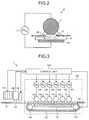
- FIG. 3 is a schematic diagram illustrating an example schematic configuration of a portion, between the plasma treatment device 100 and the inkjet head 170, of the printing apparatus (system) 1 illustrated in FIG. 1 .
- the printing apparatus (system) I includes the plasma treatment device 100, a reflecting light source 181, a hyperspectral camera 180, the inkjet head 170, and a control unit 160.
- the plasma treatment device 100 performs plasma treatment on the surface of the treatment target 20.
- the reflecting light source 181 illuminates the plasma-treated treatment target 20.
- the hyperspectral camera 180 measures a reflectance spectrum of light reflected from the treatment target 20.
- the inkjet head 17 forms an image on the treatment target 20 by inkjet recording.
- the control unit 160 performs overall control of the printing apparatus (system) 1.
- Each of high-frequency, high-voltage power sources 151 to 156 applies a high-frequency, high-voltage pulse voltage between one, to which the power source is connected, of discharge electrodes 111 to 116 and a counter electrode 141.
- the voltage value of the pulse voltage is approximately 10 kV (kilovolts), for example.
- the frequency of the pulse voltage may be approximately 20 kHz (kilohertz), for example.
- Atmospheric-pressure non-equilibrium plasma is produced between the discharge electrode 111 and a dielectric 121 by supplying such a high-frequency, high-voltage pulse voltage between the two electrodes.
- the dielectric 121 is disposed between the discharge electrodes 111 to 116 and the counter electrode 141.
- An endless belt is preferably used as the dielectric 121 so that the dielectric 121 also serve to convey the treatment target 20.
- the plasma treatment device 100 further includes rollers 122 for rotating the dielectric 121 to convey the treatment target 20.
- the rollers 122 are rotated in accordance with a command fed from the control unit 160, thereby rotating the dielectric 121.
- the treatment target 20 is conveyed through between the discharge electrode 111 and the dielectric 121 during when the atmospheric-pressure non-equilibrium plasma is produced, and is plasma-treated.
- the plasma treatment is performed in the atmosphere in this example, the plasma treatment may alternatively be performed in a gas atmosphere of nitrogen, a rare gas, or the like.
- the control unit 160 can individually turn the high-frequency, high-voltage power sources 151 to 156 on and off. Specifically, the control unit 160 can adjust the number of the discharge electrodes 111 to 116 (i.e., the number of driven electrodes) to be driven by individually turning the high-frequency, high-voltage power sources 151 to 156 on and off. Furthermore, the control unit 160 can adjust the magnitude of the pulse voltage to be supplied from each of the high-frequency, high-voltage power sources 151 to 156 to a corresponding one of the discharge electrodes 111 to 116.
- the reflecting light source 181 and the hyperspectral camera 180 which are disposed downstream from the plasma treatment device 100, measure a reflectance spectrum on the surface of the treatment target 20 having undergone the plasma treatment performed by the plasma treatment device 100. Details of the reflecting light source 181 and the hyperspectral camera 180 will be described below.
- the inkjet head 170 is disposed downstream of the plasma treatment device 100 on the conveyance path D1 for the treatment target 20.
- the inkjet head 170 ejects ink under control of the control unit 160 onto the treatment target 20 having undergone the plasma treatment performed by the plasma treatment device 100, thereby forming an image.
- the inkjet head 170 may include a plurality of heads for the same color (for example, four heads for each of four colors) to increase print speed, for example. Furthermore, to form an image at a high speed and high resolution (for example, 1,200 dpi (dots per inch)), ink ejection nozzles of the head for each color may be fixed in a staggered arrangement where the nozzles are spaced as desired. Furthermore, the inkjet head 170 may be configured to be driven at any one of a plurality of drive frequencies so that each nozzle can eject a dot (droplet) of ink in any one of three volumes referred to as large, medium, and small droplets.
- a dot droplet
- Disposing the plurality of discharge electrodes 111 to 116 along the conveyance path D1 of the treatment target 20 makes it possible to perform sequential plasma treatment and to adjust a level of plasma treatment (put another way, adjust the intensity of the plasma energy to be applied to the treatment target 20).
- FIG. 4 is a diagram illustrating an example of a treatment result when the discharge electrodes 111 to 116 are disposed in three rows along the conveyance path D1 of the treatment target 20 to thereby divide a treatment width into three and perform plasma treatment partially on the treatment target 20, for example.
- treated areas 300 and 303 are formed in one of areas, which result from the division of the treatment target 20 into three in a width direction W1 at one end by applying a pulse voltage to the discharge electrodes 111 and 114, which are situated at the one end, of the discharge electrodes 111 to 116 to cause discharge.
- the treated area 303 is an area treated with plasma produced by the discharge electrode 111, while the treated area 300 is an area treated with plasma produced by both of the discharge electrodes 111 and 114.
- treated areas 302 and 305 are formed in another one of the areas, which result from the division of the treatment target 20 into three in the width direction W1, at the other end by applying a pulse voltage to the discharge electrodes 113 and 116, which are situated at the other end, to cause discharge.
- the treated area 305 is an area treated with plasma produced by the discharge electrode 113, while the treated area 302 is an area treated with plasma produced by both of the discharge electrodes 113 and 116.
- An untreated area 301 which is not plasma-treated, is formed by applying no pulse voltage to the discharge electrodes 112 and 115 situated in the center in the width direction W1.
- disposing the discharge electrodes 111 to 116 in an array in the width direction W1 of the treatment target 20 makes it possible to adjust the levels of treatment in the width direction.
- FIG. 5 is a graph of a reflectance spectrum measured on the treatment target illustrated in FIG. 4 with plasma energy per discharge electrode set to 1 J/m 2 (joule per square meter).
- reflectance spectrum of the untreated area 301 is indicated by L1; reflectance spectrum of the treated area 300 is indicated by L2; and reflectance spectrum of the treated area 302 is indicated by L3.
- the hyperspectral camera 180 NH-7 manufactured by EBA JAPAN CO., LTD. (registered trademark) was used.
- the reflectance of the treated areas 300 and 302 is smaller than the reflectance of the untreated area 301 in a wavelength range at or below 475 nm (e.g., a wavelength range from 350 to 475 nm) and a wavelength range at or above 1020 nm (e.g., a wavelength range from 1020 to 1100 nm).
- a drop in reflectance is larger in the treated area 302 where plasma treatment is performed twice than in the treated area 300 where plasma treatment is performed once. It is implied that the greater the plasma energy per unit area applied to the treatment target 20, the greater the reflectance decreases.
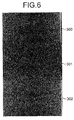
- FIG. 6 is a view illustrating a visualized image obtained by performing image processing on the treated areas 300 and 302 and the untreated area 301 of FIG. 4 based on a reflectance spectrum at a wavelength of 1020 nm.
- the treated areas 300 and 302 exhibit lighter color than the untreated area 301. This indicates that the reflectance in the treated areas 300 and 302 is smaller than the reflectance of the untreated area 301.
- Contact angles of pure water droplets on the respective areas were measured. The contact angle of pure water droplets on the treated areas 300 and 302 was 30 degrees, while the contact angle of a pure water droplet on the untreated area 301 was 70 degrees. This indicates that the treated areas 300 and 302 have higher hydrophilicity than the untreated area 301.
- a configuration for compensation to maintain uniformity of plasma treatment is achievable by evaluating uniformity of plasma treatment by two-dimensionally observing the treatment target 20. Specifically, it is possible to equalize reflectance across the entire treated surface of the treatment target 20 by feedback- or feedforward-controlling the high-frequency, high-voltage power sources 151 to 156 based on information (a reflectance spectrum) about reflectance at each of positions (e.g., coordinates) on the treated surface. Furthermore, it is also possible to adjust the level of plasma treatment (plasma energy) across the entire to-be-treated surface by controlling the high-frequency, high-voltage power sources 151 to 156 so as to maintain reflectance at or below a predetermined value at each of the positions. For instance, the predetermined reflectance value at a wavelength of 415 nm may be 0.93.
- a visualized image as illustrated in FIG. 6 can also be obtained by performing image processing based on a reflectance spectrum of light of a wavelength in a wavelength range at or below 475 nm, for example.
- a visualized image more accurately representing a result of plasma treatment can be obtained by performing image processing based on both a reflectance spectrum of light of a wavelength in a wavelength range at or below 475 nm and a reflectance spectrum of light of a wavelength in a wavelength range at or above 1020 nm, for example.
- Correction to maintain uniformity of plasma treatment performed on the treatment target 20 is enabled by evaluating uniformity of plasma treatment performed on the treatment target 20 using one or more wavelengths or wavelength ranges where variation in reflectance is produced between before and after the plasma treatment in this manner.
- the hyperspectral camera 180 measures surface reflectance of the treatment target 20 in a contactless manner, for example.
- the reflecting light source 181 irradiates the treatment target 20 with light of an appropriate intensity satisfying a measurement condition based on a signal fed from the control unit 160.
- a halogen lamp is used as the reflecting light source 181.
- any one of various light sources including a fluorescent lamp, a black light source, and infrared light source can be used depending on a purpose.
- a distance G1 between the treatment target 20 and the hyperspectral camera 180 it is possible to measure a reflectance spectrum for different purposes by changing a distance G1 between the treatment target 20 and the hyperspectral camera 180.
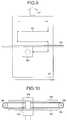
- an image may preferably be captured with the hyperspectral camera 180 positioned in proximity of the treatment target 20 as illustrated in FIG. 7 ; whereas, when it is desired to evaluate overall uniformity quickly, an image may preferably be captured with the hyperspectral camera 180 positioned away from the treatment target 20 as illustrated in FIG. 8 .
- a method of shuttling the hyperspectral camera 180 back and forth in the direction (i.e., the width direction W1 of the treatment target 20) perpendicular to the conveying direction D1 and capturing an image as illustrated in FIG. 9 can be used.
- Shuttling the hyperspectral camera 180 in the width direction W1 can be implemented by a mechanical structure as illustrated in FIG. 10 .
- a slider 183 disposed on the hyperspectral camera 180 is slidably fitted in a pair of guide rails 182 extending in the width direction W1.
- a drive force for shuttling the hyperspectral camera 180 back and forth using the slider 183 is transmitted from a gear 185 to a timing belt 184, for example.
- the timing belt 184 is fixed to the slider 183 at one point.
- the timing belt 184 is entrained around the gear 185 and a pulley 186 to apply a necessary and sufficient tension to the timing belt 184.
- the treatment target 20 is moved a predetermined distance in the conveying direction D1 each time switching between forward rotation and backward rotation of the gear 185 occurs.
- the hyperspectral camera 180 can be moved relative to the treatment target 20 as indicated by arrows M1 in FIG. 9 .
- the reflectance spectrum measured by the hyperspectral camera 180 is fed to the control unit 160.
- the hyperspectral camera 180 is shuttled back and forth as illustrated in FIG. 9 , it is possible to visualize a reflectance spectrum of an area (e.g., the entire treated surface) wider than a field of view of the hyperspectral camera 180 at a high resolution by repeatedly moving the hyperspectral camera 180, stopping the hyperspectral camera 180, capturing images, and merging, by the control unit 160, the thus-measured local reflectance spectra.
- the control unit 160 evaluates reflectance uniformity based on the reflectance spectrum fed to the control unit 160 and adjusts the number of the discharge electrodes 111 to 116 to be driven and/or the plasma energy of the pulse voltages supplied from the high-frequency, high-voltage power sources 151 to 156 to the discharge electrodes 111 to 116 according to a result of the evaluation.
- Example methods usable to reduce the plasma treatment duration include a method of, as described above, disposing the plurality of discharge electrodes 111 to 116 and driving a necessary number of the discharge electrodes 111 to 116 depending on a print speed and required reflectance and a method of adjusting the intensity of plasma energy supplied to the respective discharge electrodes 111 to 116.
- the method is not limited to these methods, and can be modified as appropriate. For example, a combination of these methods or another method can be used.
- FIG. 11 is a flowchart illustrating an example of a printing process including the hydrophilization treatment (plasma treatment) according to the embodiment.
- FIG. 11 illustrates an example where the printing apparatus (system) 1 including the plasma treatment device 100 illustrated in FIG. 3 performs printing on a sheet of cut paper (a recording medium cut into a predetermined size), which is the treatment target 20.
- the recording medium is not limited to cut paper; printing can be performed similarly on roll paper, which is paper rolled into a roll.
- the printing process is performed as illustrated in FIG. 11 .
- the control unit 160 drives the rollers 122 to rotate the dielectric 121, thereby feeding the treatment target 20, which has been conveyed onto the dielectric 121 from upstream, into the plasma treatment device 100 (S101). Thereafter, the control unit 160 drives the high-frequency, high-voltage power sources 151 to 156 to supply pulse voltages to the discharge electrodes 111 to 116, thereby performing plasma treatment (S102).
- the plasma treatment is performed in the following manner. If a result of measurement is not fed from the hyperspectral camera 180, the control unit 160 supplies plasma energy of a predetermined intensity to the discharge electrodes 111 to 116.
- control unit 160 adjusts the number of the high-frequency, high-voltage power sources 151 to 156 to be driven according to the measurement result. At this time, the control unit 160 may further adjust the plasma energy to be supplied to each of the discharge electrodes 111 to 116.
- the control unit 160 drives the reflecting light source 181 and the hyperspectral camera 180 to capture an image of the plasma-treated treatment target 20 (S103) and performs image processing thereon to visualize the obtained reflectance spectrum (S104).
- reflectance spectra values obtained by the hyperspectral camera 180 are converted into grayscale tonal values on a pixel-by-pixel basis, thereby obtaining a visualized two-dimensional mapping image.
- the conversion from the values of the reflectance spectrum into the tonal values can be performed using a conversion equation determined by initial settings, which will be described below with reference to FIG. 12 , for example.
- the control unit 160 analyzes the obtained visualized image to evaluate uniformity of the plasma treatment (S105). Evaluation of the uniformity of the plasma treatment is made based on, for example, variation in tonal values of the respective pixels.
- the control unit 160 determines whether or not the uniformity of the plasma treatment is within an allowable range (S106). If the uniformity is not within the allowable range (NO at S106), the control unit 160 determines whether or not adjustment is possible by changing plasma treatment conditions (S109). The control unit 160 determines that adjustment is possible when, for example, it is judged that it is possible to bring the uniformity into the allowable range by adjusting the number of the high-frequency, high-voltage power sources 151 to 156 to be driven, the intensity of the plasma energy to be supplied to the respective discharge electrodes 111 to 116, the conveyance velocity (linear velocity), and/or the like. The control unit 160 determines that adjustment is impossible when, for example, a foreign matter sticking to the discharge electrodes 111 to 116 or the counter electrode 141, or the like makes discharge unstable and causes thin-stripe-shaped treatment unevenness.
- control unit 160 determines that adjustment is possible (YES at S109)
- the control unit 160 optimizes the number of the high-frequency, high-voltage power sources 151 to 156 to be driven, the intensity of the plasma energy to be supplied to the respective discharge electrodes 111 to 116, the conveyance velocity (linear velocity), and/or the like (S110). Processing then returns to S102. Consequently, because distribution of the plasma energy over the treatment target 20 is equalized, uniformity of the surface, which is treated with the plasma, of the treatment target 20 is increased.
- the control unit 160 determines that adjustment is impossible (NO at S109)
- the control unit 160 stops the printing process (S111), reports the error of the printing process to a user (S112), and completes the operation.
- control unit 160 determines that the uniformity of the plasma treatment is within the allowable range at S106 (YES at S106)
- the control unit 160 drives the inkjet head 170 to perform an inkjet recording process on the plasma-treated treatment target 20 (S107). Thereafter, the control unit 160 conveys out the treatment target 20 from the inkjet head 170 downstream (S108), and completes the operation.
- the control unit 160 may alternatively be configured such that, if the control unit 160 determines that the uniformity is not within the allowable range at S105, the control unit 160 routes the treatment target 20 through a bypass route (not illustrated) to perform plasma treatment again on the same treatment target 20 (S102). Thereby, the treatment target 20 can be prevented from being wasted. Further, even when a plurality of types of recording media that differ in property are used as the treatment target 20, the treatment can be performed by a similar procedure.
- a configuration for locally performing plasma treatment based on print image data in advance and checking the corresponding area having been plasma-treated using the hyperspectral camera 180, and performing a printing process can be used. This configuration allows omitting application of plasma treatment to an unnecessary area, thereby achieving reduction of power consumption.
- FIG. 12 An initial setting operation for evaluating uniformity of plasma treatment is performed as illustrated in FIG. 12 .
- the feed-in unit 30 feeds in the treatment target 20 onto the conveyance path first (S001).
- the fed-in treatment target 20 is moved through the plasma treatment device 100, without being plasma-treated, into the field of view of the hyperspectral camera 180 and the hyperspectral camera 180 measures a reflectance spectrum (S002).
- the reflectance spectrum obtained by making measurement (blank measurement) of the not-plasma-treated treatment target 20 are used as offset (also called "background") of respective pixels in evaluation of the uniformity.
- the control unit 160 drives the plasma treatment device 100 to perform plasma treatment on the treatment target 20 (S003).
- the treatment target 20 to be treated at this time may be either the treatment target 20 having undergone the blank measurement at S002 and conveyed in reverse or the treatment target 20 newly fed in by the feed-in unit 30.
- a sample treated with high plasma energy per unit area may be prepared by conveying the treatment target 20 at a minimum conveyance velocity, for example.
- a sample where intensity of applied plasma energy varies from one area to another may be prepared by causing the number of the discharge electrodes 111 to 116 to be used to vary stepwise.
- the treatment target 20 (or the sample) plasma-treated as described above is moved into the field of view of the hyperspectral camera 180 and an image of the treatment target 20 is captured (S004).
- the control unit 160 performs image processing on the reflectance spectrum obtained by capturing the image to perform visualization (S005).
- Various methods can be used as a method for assigning tonal values in the visualization.
- Examples of the usable various methods include a method of proportionally distributing tonal values to reflectivities, in which atonal value of 255 is assigned to reflectivity of an untreated area where plasma treatment is not performed and a tonal value of 0 is assigned to an area where reflectivity is lowest among treated areas, and a method of calculating the slope from reflectivity at 1100 nm and reflectivity at 950 nm and performing image processing with a tonal value of 255 assigned to a slope of 0 and a tonal value of 0 assigned to a slope of infinity.
- control unit 160 determines a conversion equation for conversion between tonal values (i.e., values of the reflectance spectrum) and plasma energy based on the plasma energy applied to the treatment target 20 on a per-area basis (or on a per-pixel basis) and tonal values of the areas (or the pixels) (S006), and completes the initial setting operation.
- tonal values i.e., values of the reflectance spectrum
- plasma energy based on the plasma energy applied to the treatment target 20 on a per-area basis (or on a per-pixel basis) and tonal values of the areas (or the pixels) (S006)
- the visualization is performed with reference to the reflectance spectrum at 1050 nm where the treatment target is less likely to be affected by fluorescent dyes contained in paper.
- a treatment target such as a film, which does not contain a fluorescent dye
- near-ultraviolet reflectance spectrum at or near 350 nm may be used.
- the initial settings illustrated in FIG. 12 may be performed using a leading-end portion of the roll paper fed by a paper feeder (not illustrated).
- Roll paper has approximately uniform properties across the entire length. Accordingly, when roll paper is used, once plasma energy is adjusted using a leading end portion of the roll paper, continuous printing can be performed stably without changing the initial settings. However, if printing should be suspended for a long period of time before all the roll paper is used up, the properties of the paper can change. In this case, it is preferable to perform the initial settings using a leading-end portion in a similar manner before resuming printing.
- a configuration where, after a reflectance spectrum of a plasma-treated leading-end portion have been measured and plasma energy has been adjusted based on the reflectance spectrum, measurement of a reflectance spectrum and adjustment of plasma energy are performed at regular intervals or continuously may be employed. This configuration allows performing control more minutely and stably.
- the hyperspectral camera 180 described in the embodiment has the sensitivity range of from 350 to 1050 nm. However, further increase in sensitivity or application to precoated paper is enabled by using the hyperspectral camera 180 having a wider sensitivity range and selecting the reflecting light source 181 of an appropriate wavelength range.
- Processing circuitry includes a programmed processor, as a processor includes circuitry.
- a processing circuit also includes devices such as an application specific integrated circuit (ASIC), digital signal processor (DSP), field programmable gate array (FPGA) and conventional circuit components arranged to perform the recited functions.
- ASIC application specific integrated circuit
- DSP digital signal processor
- FPGA field programmable gate array
Landscapes
- Physics & Mathematics (AREA)
- Engineering & Computer Science (AREA)
- Plasma & Fusion (AREA)
- Chemical & Material Sciences (AREA)
- Analytical Chemistry (AREA)
- Spectroscopy & Molecular Physics (AREA)
- Quality & Reliability (AREA)
- Ink Jet (AREA)
- Plasma Technology (AREA)
- Investigating, Analyzing Materials By Fluorescence Or Luminescence (AREA)
Applications Claiming Priority (1)
| Application Number | Priority Date | Filing Date | Title |
|---|---|---|---|
| JP2015133894A JP2017013408A (ja) | 2015-07-02 | 2015-07-02 | 被処理物改質装置、被処理物改質システム、画像形成システムおよび画像形成方法 |
Publications (2)
| Publication Number | Publication Date |
|---|---|
| EP3124256A1 true EP3124256A1 (de) | 2017-02-01 |
| EP3124256B1 EP3124256B1 (de) | 2020-04-08 |
Family
ID=56203240
Family Applications (1)
| Application Number | Title | Priority Date | Filing Date |
|---|---|---|---|
| EP16175972.5A Active EP3124256B1 (de) | 2015-07-02 | 2016-06-23 | Behandlungszielmodifikationsvorrichtung, behandlungszielmodifikationssystem, bilderzeugungssystem und bilderzeugungsverfahren |
Country Status (4)
| Country | Link |
|---|---|
| US (1) | US10105966B2 (de) |
| EP (1) | EP3124256B1 (de) |
| JP (1) | JP2017013408A (de) |
| CN (1) | CN106313919B (de) |
Cited By (1)
| Publication number | Priority date | Publication date | Assignee | Title |
|---|---|---|---|---|
| WO2020161272A1 (de) * | 2019-02-07 | 2020-08-13 | Windmöller & Hölscher Kg | Verfahren und vorrichtung zur oberflächenbehandlung eines druckmediums |
Families Citing this family (5)
| Publication number | Priority date | Publication date | Assignee | Title |
|---|---|---|---|---|
| JP2020139880A (ja) | 2019-02-28 | 2020-09-03 | 株式会社リコー | 分析方法、分析装置、印刷装置、および、印刷システム |
| KR20220034456A (ko) * | 2020-09-11 | 2022-03-18 | 주식회사 싸이큐어 | 표면 및 공간 led 살균 조명장치 |
| US12202278B2 (en) | 2022-03-19 | 2025-01-21 | Ricoh Company, Ltd. | Printer |
| JP2024076747A (ja) | 2022-11-25 | 2024-06-06 | 株式会社リコー | メンテナンス方法及び液体吐出装置 |
| EP4461541B1 (de) * | 2023-05-11 | 2026-01-28 | SWISS KRONO Tec AG | Verfahren und vorrichtung zum vorbeugen von druckfehlern beim digitaldruck durch fehlerbehaftete druckdüsen |
Citations (5)
| Publication number | Priority date | Publication date | Assignee | Title |
|---|---|---|---|---|
| JP2005350615A (ja) | 2004-06-14 | 2005-12-22 | Toray Ind Inc | 2軸延伸ポリエステルフィルム |
| JP2013193291A (ja) | 2012-03-19 | 2013-09-30 | Seiko Epson Corp | 画像記録装置、画像記録方法 |
| JP2014016618A (ja) | 2009-05-27 | 2014-01-30 | Seiko Epson Corp | 光フィルター、光フィルター装置、および分析機器 |
| JP2014076658A (ja) * | 2012-09-18 | 2014-05-01 | Ricoh Co Ltd | 印刷装置、印刷システムおよび印刷物の製造方法 |
| JP2015057309A (ja) * | 2012-09-18 | 2015-03-26 | 株式会社リコー | 印刷装置、印刷システムおよび印刷物の製造方法 |
Family Cites Families (19)
| Publication number | Priority date | Publication date | Assignee | Title |
|---|---|---|---|---|
| GB9219450D0 (en) | 1992-09-15 | 1992-10-28 | Glaverbel | Thin film thickness monitoring and control |
| US20040055698A1 (en) | 2002-09-24 | 2004-03-25 | Tran Hai Q. | Method of improving lamination quality by treating media with plasma |
| EP1403333A1 (de) * | 2002-09-24 | 2004-03-31 | Sicpa Holding S.A. | Verfahren und Tintensatz zur Markierung und Beurkundung von Artikeln |
| JP2009279796A (ja) | 2008-05-20 | 2009-12-03 | Tohoku Ricoh Co Ltd | インクジェット記録方法及びインクジェット記録装置 |
| JP4575978B2 (ja) | 2008-10-31 | 2010-11-04 | 日東電工株式会社 | 液晶表示装置 |
| JP5370246B2 (ja) | 2009-05-27 | 2013-12-18 | セイコーエプソン株式会社 | 光フィルター、光フィルター装置、分析機器、および光フィルターの製造方法 |
| JP5620135B2 (ja) | 2010-03-31 | 2014-11-05 | 富士フイルム株式会社 | 印字装置および印字方法 |
| US9259924B2 (en) | 2012-09-18 | 2016-02-16 | Ricoh Company, Ltd. | Printing apparatus and printed material manufacturing method |
| JP6314417B2 (ja) | 2012-12-12 | 2018-04-25 | 株式会社リコー | 印刷装置、印刷物の製造方法および印刷システム |
| JP6592877B2 (ja) | 2013-07-31 | 2019-10-23 | 株式会社リコー | 印刷装置、印刷システムおよび印刷物の製造方法 |
| JP6497004B2 (ja) | 2013-09-13 | 2019-04-10 | 株式会社リコー | 印刷装置、印刷システムおよび印刷物の製造方法 |
| JP6492685B2 (ja) | 2014-03-07 | 2019-04-03 | 株式会社リコー | 印刷装置、印刷システム、プログラムおよび印刷物の製造方法 |
| JP6476928B2 (ja) | 2014-03-11 | 2019-03-06 | 株式会社リコー | 印刷装置、印刷システム、および印刷物の製造方法 |
| JP6503713B2 (ja) | 2014-03-11 | 2019-04-24 | 株式会社リコー | 印刷装置、印刷システムおよび印刷物の製造方法 |
| JP6586725B2 (ja) | 2014-03-18 | 2019-10-09 | 株式会社リコー | 印刷装置、印刷システム、印刷物の製造方法、およびプログラム |
| JP2015193217A (ja) | 2014-03-18 | 2015-11-05 | 株式会社リコー | 印刷装置、印刷システム、印刷物の製造方法、およびプログラム |
| JP6485197B2 (ja) | 2014-07-10 | 2019-03-20 | 株式会社リコー | 印刷装置、印刷システム、印刷物の製造方法、およびプログラム |
| US9352589B2 (en) | 2014-10-02 | 2016-05-31 | Ricoh Company, Ltd. | Modification device, modification method, computer program product, image forming apparatus, and image forming system |
| CN204346906U (zh) | 2014-11-20 | 2015-05-20 | 中国建筑材料科学研究总院 | 在线光谱测量装置及透明介质膜层均匀性在线测量装置 |
-
2015
- 2015-07-02 JP JP2015133894A patent/JP2017013408A/ja active Pending
-
2016
- 2016-06-21 US US15/188,806 patent/US10105966B2/en not_active Expired - Fee Related
- 2016-06-23 EP EP16175972.5A patent/EP3124256B1/de active Active
- 2016-06-30 CN CN201610509520.4A patent/CN106313919B/zh not_active Expired - Fee Related
Patent Citations (5)
| Publication number | Priority date | Publication date | Assignee | Title |
|---|---|---|---|---|
| JP2005350615A (ja) | 2004-06-14 | 2005-12-22 | Toray Ind Inc | 2軸延伸ポリエステルフィルム |
| JP2014016618A (ja) | 2009-05-27 | 2014-01-30 | Seiko Epson Corp | 光フィルター、光フィルター装置、および分析機器 |
| JP2013193291A (ja) | 2012-03-19 | 2013-09-30 | Seiko Epson Corp | 画像記録装置、画像記録方法 |
| JP2014076658A (ja) * | 2012-09-18 | 2014-05-01 | Ricoh Co Ltd | 印刷装置、印刷システムおよび印刷物の製造方法 |
| JP2015057309A (ja) * | 2012-09-18 | 2015-03-26 | 株式会社リコー | 印刷装置、印刷システムおよび印刷物の製造方法 |
Cited By (1)
| Publication number | Priority date | Publication date | Assignee | Title |
|---|---|---|---|---|
| WO2020161272A1 (de) * | 2019-02-07 | 2020-08-13 | Windmöller & Hölscher Kg | Verfahren und vorrichtung zur oberflächenbehandlung eines druckmediums |
Also Published As
| Publication number | Publication date |
|---|---|
| CN106313919B (zh) | 2019-05-03 |
| CN106313919A (zh) | 2017-01-11 |
| JP2017013408A (ja) | 2017-01-19 |
| US10105966B2 (en) | 2018-10-23 |
| EP3124256B1 (de) | 2020-04-08 |
| US20170001453A1 (en) | 2017-01-05 |
Similar Documents
| Publication | Publication Date | Title |
|---|---|---|
| EP3124256B1 (de) | Behandlungszielmodifikationsvorrichtung, behandlungszielmodifikationssystem, bilderzeugungssystem und bilderzeugungsverfahren | |
| US10279604B2 (en) | Printing apparatus and printed material manufacturing method | |
| US9108437B2 (en) | Printing apparatus, treatment object modifying apparatus, printing system, and printed material manufacturing method | |
| JP6435896B2 (ja) | 被処理物改質装置、印刷装置、印刷システムおよび印刷物の製造方法 | |
| JP6492685B2 (ja) | 印刷装置、印刷システム、プログラムおよび印刷物の製造方法 | |
| US9403382B2 (en) | Printing apparatus, printing system, and printed material manufacturing method | |
| US9242482B2 (en) | pH detecting device, printing system, and method for manufacturing printed material | |
| JP6503655B2 (ja) | 被処理物改質装置、印刷装置、印刷システムおよび印刷物の製造方法 | |
| US9387695B2 (en) | Plasma treatment apparatus, printing apparatus, printing system, and method of producing printed matter | |
| JP6558464B2 (ja) | インクジェット記録装置およびインクジェット記録方法 | |
| US9487026B2 (en) | Printing apparatus, printing system, and manufacturing method of printed matter | |
| JP6311242B2 (ja) | 印刷装置、印刷システムおよび印刷物の製造方法 |
Legal Events
| Date | Code | Title | Description |
|---|---|---|---|
| PUAI | Public reference made under article 153(3) epc to a published international application that has entered the european phase |
Free format text: ORIGINAL CODE: 0009012 |
|
| STAA | Information on the status of an ep patent application or granted ep patent |
Free format text: STATUS: REQUEST FOR EXAMINATION WAS MADE |
|
| 17P | Request for examination filed |
Effective date: 20160623 |
|
| AK | Designated contracting states |
Kind code of ref document: A1 Designated state(s): AL AT BE BG CH CY CZ DE DK EE ES FI FR GB GR HR HU IE IS IT LI LT LU LV MC MK MT NL NO PL PT RO RS SE SI SK SM TR |
|
| AX | Request for extension of the european patent |
Extension state: BA ME |
|
| STAA | Information on the status of an ep patent application or granted ep patent |
Free format text: STATUS: EXAMINATION IS IN PROGRESS |
|
| 17Q | First examination report despatched |
Effective date: 20190522 |
|
| REG | Reference to a national code |
Ref country code: DE Ref legal event code: R079 Ref document number: 602016033393 Country of ref document: DE Free format text: PREVIOUS MAIN CLASS: B41J0002515000 Ipc: B41J0002010000 |
|
| GRAP | Despatch of communication of intention to grant a patent |
Free format text: ORIGINAL CODE: EPIDOSNIGR1 |
|
| STAA | Information on the status of an ep patent application or granted ep patent |
Free format text: STATUS: GRANT OF PATENT IS INTENDED |
|
| RIC1 | Information provided on ipc code assigned before grant |
Ipc: H01J 37/32 20060101ALI20191104BHEP Ipc: B41J 2/21 20060101ALN20191104BHEP Ipc: B41J 11/00 20060101ALI20191104BHEP Ipc: B41J 2/01 20060101AFI20191104BHEP Ipc: B41J 2/515 20060101ALI20191104BHEP Ipc: B41M 5/00 20060101ALI20191104BHEP |
|
| INTG | Intention to grant announced |
Effective date: 20191119 |
|
| GRAS | Grant fee paid |
Free format text: ORIGINAL CODE: EPIDOSNIGR3 |
|
| GRAA | (expected) grant |
Free format text: ORIGINAL CODE: 0009210 |
|
| STAA | Information on the status of an ep patent application or granted ep patent |
Free format text: STATUS: THE PATENT HAS BEEN GRANTED |
|
| AK | Designated contracting states |
Kind code of ref document: B1 Designated state(s): AL AT BE BG CH CY CZ DE DK EE ES FI FR GB GR HR HU IE IS IT LI LT LU LV MC MK MT NL NO PL PT RO RS SE SI SK SM TR |
|
| REG | Reference to a national code |
Ref country code: CH Ref legal event code: EP Ref country code: AT Ref legal event code: REF Ref document number: 1253836 Country of ref document: AT Kind code of ref document: T Effective date: 20200415 |
|
| REG | Reference to a national code |
Ref country code: DE Ref legal event code: R096 Ref document number: 602016033393 Country of ref document: DE |
|
| REG | Reference to a national code |
Ref country code: IE Ref legal event code: FG4D |
|
| REG | Reference to a national code |
Ref country code: NL Ref legal event code: FP |
|
| REG | Reference to a national code |
Ref country code: LT Ref legal event code: MG4D |
|
| PG25 | Lapsed in a contracting state [announced via postgrant information from national office to epo] |
Ref country code: LT Free format text: LAPSE BECAUSE OF FAILURE TO SUBMIT A TRANSLATION OF THE DESCRIPTION OR TO PAY THE FEE WITHIN THE PRESCRIBED TIME-LIMIT Effective date: 20200408 Ref country code: SE Free format text: LAPSE BECAUSE OF FAILURE TO SUBMIT A TRANSLATION OF THE DESCRIPTION OR TO PAY THE FEE WITHIN THE PRESCRIBED TIME-LIMIT Effective date: 20200408 Ref country code: FI Free format text: LAPSE BECAUSE OF FAILURE TO SUBMIT A TRANSLATION OF THE DESCRIPTION OR TO PAY THE FEE WITHIN THE PRESCRIBED TIME-LIMIT Effective date: 20200408 Ref country code: IS Free format text: LAPSE BECAUSE OF FAILURE TO SUBMIT A TRANSLATION OF THE DESCRIPTION OR TO PAY THE FEE WITHIN THE PRESCRIBED TIME-LIMIT Effective date: 20200808 Ref country code: GR Free format text: LAPSE BECAUSE OF FAILURE TO SUBMIT A TRANSLATION OF THE DESCRIPTION OR TO PAY THE FEE WITHIN THE PRESCRIBED TIME-LIMIT Effective date: 20200709 Ref country code: NO Free format text: LAPSE BECAUSE OF FAILURE TO SUBMIT A TRANSLATION OF THE DESCRIPTION OR TO PAY THE FEE WITHIN THE PRESCRIBED TIME-LIMIT Effective date: 20200708 Ref country code: PT Free format text: LAPSE BECAUSE OF FAILURE TO SUBMIT A TRANSLATION OF THE DESCRIPTION OR TO PAY THE FEE WITHIN THE PRESCRIBED TIME-LIMIT Effective date: 20200817 |
|
| REG | Reference to a national code |
Ref country code: AT Ref legal event code: MK05 Ref document number: 1253836 Country of ref document: AT Kind code of ref document: T Effective date: 20200408 |
|
| PG25 | Lapsed in a contracting state [announced via postgrant information from national office to epo] |
Ref country code: LV Free format text: LAPSE BECAUSE OF FAILURE TO SUBMIT A TRANSLATION OF THE DESCRIPTION OR TO PAY THE FEE WITHIN THE PRESCRIBED TIME-LIMIT Effective date: 20200408 Ref country code: RS Free format text: LAPSE BECAUSE OF FAILURE TO SUBMIT A TRANSLATION OF THE DESCRIPTION OR TO PAY THE FEE WITHIN THE PRESCRIBED TIME-LIMIT Effective date: 20200408 Ref country code: BG Free format text: LAPSE BECAUSE OF FAILURE TO SUBMIT A TRANSLATION OF THE DESCRIPTION OR TO PAY THE FEE WITHIN THE PRESCRIBED TIME-LIMIT Effective date: 20200708 Ref country code: HR Free format text: LAPSE BECAUSE OF FAILURE TO SUBMIT A TRANSLATION OF THE DESCRIPTION OR TO PAY THE FEE WITHIN THE PRESCRIBED TIME-LIMIT Effective date: 20200408 |
|
| PG25 | Lapsed in a contracting state [announced via postgrant information from national office to epo] |
Ref country code: AL Free format text: LAPSE BECAUSE OF FAILURE TO SUBMIT A TRANSLATION OF THE DESCRIPTION OR TO PAY THE FEE WITHIN THE PRESCRIBED TIME-LIMIT Effective date: 20200408 |
|
| REG | Reference to a national code |
Ref country code: DE Ref legal event code: R097 Ref document number: 602016033393 Country of ref document: DE |
|
| PG25 | Lapsed in a contracting state [announced via postgrant information from national office to epo] |
Ref country code: CZ Free format text: LAPSE BECAUSE OF FAILURE TO SUBMIT A TRANSLATION OF THE DESCRIPTION OR TO PAY THE FEE WITHIN THE PRESCRIBED TIME-LIMIT Effective date: 20200408 Ref country code: IT Free format text: LAPSE BECAUSE OF FAILURE TO SUBMIT A TRANSLATION OF THE DESCRIPTION OR TO PAY THE FEE WITHIN THE PRESCRIBED TIME-LIMIT Effective date: 20200408 Ref country code: RO Free format text: LAPSE BECAUSE OF FAILURE TO SUBMIT A TRANSLATION OF THE DESCRIPTION OR TO PAY THE FEE WITHIN THE PRESCRIBED TIME-LIMIT Effective date: 20200408 Ref country code: EE Free format text: LAPSE BECAUSE OF FAILURE TO SUBMIT A TRANSLATION OF THE DESCRIPTION OR TO PAY THE FEE WITHIN THE PRESCRIBED TIME-LIMIT Effective date: 20200408 Ref country code: SM Free format text: LAPSE BECAUSE OF FAILURE TO SUBMIT A TRANSLATION OF THE DESCRIPTION OR TO PAY THE FEE WITHIN THE PRESCRIBED TIME-LIMIT Effective date: 20200408 Ref country code: AT Free format text: LAPSE BECAUSE OF FAILURE TO SUBMIT A TRANSLATION OF THE DESCRIPTION OR TO PAY THE FEE WITHIN THE PRESCRIBED TIME-LIMIT Effective date: 20200408 Ref country code: DK Free format text: LAPSE BECAUSE OF FAILURE TO SUBMIT A TRANSLATION OF THE DESCRIPTION OR TO PAY THE FEE WITHIN THE PRESCRIBED TIME-LIMIT Effective date: 20200408 Ref country code: ES Free format text: LAPSE BECAUSE OF FAILURE TO SUBMIT A TRANSLATION OF THE DESCRIPTION OR TO PAY THE FEE WITHIN THE PRESCRIBED TIME-LIMIT Effective date: 20200408 Ref country code: MC Free format text: LAPSE BECAUSE OF FAILURE TO SUBMIT A TRANSLATION OF THE DESCRIPTION OR TO PAY THE FEE WITHIN THE PRESCRIBED TIME-LIMIT Effective date: 20200408 |
|
| REG | Reference to a national code |
Ref country code: CH Ref legal event code: PL |
|
| PLBE | No opposition filed within time limit |
Free format text: ORIGINAL CODE: 0009261 |
|
| STAA | Information on the status of an ep patent application or granted ep patent |
Free format text: STATUS: NO OPPOSITION FILED WITHIN TIME LIMIT |
|
| PG25 | Lapsed in a contracting state [announced via postgrant information from national office to epo] |
Ref country code: SK Free format text: LAPSE BECAUSE OF FAILURE TO SUBMIT A TRANSLATION OF THE DESCRIPTION OR TO PAY THE FEE WITHIN THE PRESCRIBED TIME-LIMIT Effective date: 20200408 Ref country code: PL Free format text: LAPSE BECAUSE OF FAILURE TO SUBMIT A TRANSLATION OF THE DESCRIPTION OR TO PAY THE FEE WITHIN THE PRESCRIBED TIME-LIMIT Effective date: 20200408 |
|
| 26N | No opposition filed |
Effective date: 20210112 |
|
| PG25 | Lapsed in a contracting state [announced via postgrant information from national office to epo] |
Ref country code: LU Free format text: LAPSE BECAUSE OF NON-PAYMENT OF DUE FEES Effective date: 20200623 |
|
| REG | Reference to a national code |
Ref country code: BE Ref legal event code: MM Effective date: 20200630 |
|
| PG25 | Lapsed in a contracting state [announced via postgrant information from national office to epo] |
Ref country code: LI Free format text: LAPSE BECAUSE OF NON-PAYMENT OF DUE FEES Effective date: 20200630 Ref country code: CH Free format text: LAPSE BECAUSE OF NON-PAYMENT OF DUE FEES Effective date: 20200630 Ref country code: IE Free format text: LAPSE BECAUSE OF NON-PAYMENT OF DUE FEES Effective date: 20200623 |
|
| PG25 | Lapsed in a contracting state [announced via postgrant information from national office to epo] |
Ref country code: BE Free format text: LAPSE BECAUSE OF NON-PAYMENT OF DUE FEES Effective date: 20200630 Ref country code: SI Free format text: LAPSE BECAUSE OF FAILURE TO SUBMIT A TRANSLATION OF THE DESCRIPTION OR TO PAY THE FEE WITHIN THE PRESCRIBED TIME-LIMIT Effective date: 20200408 |
|
| PG25 | Lapsed in a contracting state [announced via postgrant information from national office to epo] |
Ref country code: TR Free format text: LAPSE BECAUSE OF FAILURE TO SUBMIT A TRANSLATION OF THE DESCRIPTION OR TO PAY THE FEE WITHIN THE PRESCRIBED TIME-LIMIT Effective date: 20200408 Ref country code: MT Free format text: LAPSE BECAUSE OF FAILURE TO SUBMIT A TRANSLATION OF THE DESCRIPTION OR TO PAY THE FEE WITHIN THE PRESCRIBED TIME-LIMIT Effective date: 20200408 Ref country code: CY Free format text: LAPSE BECAUSE OF FAILURE TO SUBMIT A TRANSLATION OF THE DESCRIPTION OR TO PAY THE FEE WITHIN THE PRESCRIBED TIME-LIMIT Effective date: 20200408 |
|
| PG25 | Lapsed in a contracting state [announced via postgrant information from national office to epo] |
Ref country code: MK Free format text: LAPSE BECAUSE OF FAILURE TO SUBMIT A TRANSLATION OF THE DESCRIPTION OR TO PAY THE FEE WITHIN THE PRESCRIBED TIME-LIMIT Effective date: 20200408 |
|
| PGFP | Annual fee paid to national office [announced via postgrant information from national office to epo] |
Ref country code: NL Payment date: 20220620 Year of fee payment: 7 Ref country code: GB Payment date: 20220627 Year of fee payment: 7 Ref country code: DE Payment date: 20220620 Year of fee payment: 7 |
|
| PGFP | Annual fee paid to national office [announced via postgrant information from national office to epo] |
Ref country code: FR Payment date: 20220628 Year of fee payment: 7 |
|
| P01 | Opt-out of the competence of the unified patent court (upc) registered |
Effective date: 20230522 |
|
| REG | Reference to a national code |
Ref country code: DE Ref legal event code: R119 Ref document number: 602016033393 Country of ref document: DE |
|
| REG | Reference to a national code |
Ref country code: NL Ref legal event code: MM Effective date: 20230701 |
|
| GBPC | Gb: european patent ceased through non-payment of renewal fee |
Effective date: 20230623 |
|
| PG25 | Lapsed in a contracting state [announced via postgrant information from national office to epo] |
Ref country code: NL Free format text: LAPSE BECAUSE OF NON-PAYMENT OF DUE FEES Effective date: 20230701 |
|
| PG25 | Lapsed in a contracting state [announced via postgrant information from national office to epo] |
Ref country code: DE Free format text: LAPSE BECAUSE OF NON-PAYMENT OF DUE FEES Effective date: 20240103 Ref country code: GB Free format text: LAPSE BECAUSE OF NON-PAYMENT OF DUE FEES Effective date: 20230623 |
|
| PG25 | Lapsed in a contracting state [announced via postgrant information from national office to epo] |
Ref country code: FR Free format text: LAPSE BECAUSE OF NON-PAYMENT OF DUE FEES Effective date: 20230630 |