EP3122672B1 - Gripper - Google Patents
Gripper Download PDFInfo
- Publication number
- EP3122672B1 EP3122672B1 EP15769503.2A EP15769503A EP3122672B1 EP 3122672 B1 EP3122672 B1 EP 3122672B1 EP 15769503 A EP15769503 A EP 15769503A EP 3122672 B1 EP3122672 B1 EP 3122672B1
- Authority
- EP
- European Patent Office
- Prior art keywords
- gripper
- wedge
- finger
- edge
- lower finger
- Prior art date
- Legal status (The legal status is an assumption and is not a legal conclusion. Google has not performed a legal analysis and makes no representation as to the accuracy of the status listed.)
- Active
Links
- 239000000758 substrate Substances 0.000 claims description 44
- 238000003780 insertion Methods 0.000 claims description 4
- 230000037431 insertion Effects 0.000 claims description 4
- 239000002184 metal Substances 0.000 claims description 4
- 238000006073 displacement reaction Methods 0.000 description 3
- 230000000694 effects Effects 0.000 description 3
- 230000005611 electricity Effects 0.000 description 3
- 238000006748 scratching Methods 0.000 description 3
- 230000002393 scratching effect Effects 0.000 description 3
- 230000003068 static effect Effects 0.000 description 3
- 230000008901 benefit Effects 0.000 description 2
- 230000000284 resting effect Effects 0.000 description 2
- 230000000630 rising effect Effects 0.000 description 2
- 230000001154 acute effect Effects 0.000 description 1
- 238000005273 aeration Methods 0.000 description 1
- 238000013459 approach Methods 0.000 description 1
- 238000007664 blowing Methods 0.000 description 1
- 230000000295 complement effect Effects 0.000 description 1
- 239000011888 foil Substances 0.000 description 1
- 230000000116 mitigating effect Effects 0.000 description 1
- 235000015927 pasta Nutrition 0.000 description 1
- 235000014594 pastries Nutrition 0.000 description 1
- 230000007704 transition Effects 0.000 description 1
Images
Classifications
-
- B—PERFORMING OPERATIONS; TRANSPORTING
- B65—CONVEYING; PACKING; STORING; HANDLING THIN OR FILAMENTARY MATERIAL
- B65H—HANDLING THIN OR FILAMENTARY MATERIAL, e.g. SHEETS, WEBS, CABLES
- B65H3/00—Separating articles from piles
- B65H3/32—Separating articles from piles by elements, e.g. fingers, plates, rollers, inserted or traversed between articles to be separated and remainder of the pile
- B65H3/322—Separating articles from piles by elements, e.g. fingers, plates, rollers, inserted or traversed between articles to be separated and remainder of the pile for separating a part of the pile, i.e. several articles at once
-
- B—PERFORMING OPERATIONS; TRANSPORTING
- B25—HAND TOOLS; PORTABLE POWER-DRIVEN TOOLS; MANIPULATORS
- B25J—MANIPULATORS; CHAMBERS PROVIDED WITH MANIPULATION DEVICES
- B25J15/00—Gripping heads and other end effectors
- B25J15/0014—Gripping heads and other end effectors having fork, comb or plate shaped means for engaging the lower surface on a object to be transported
-
- B—PERFORMING OPERATIONS; TRANSPORTING
- B25—HAND TOOLS; PORTABLE POWER-DRIVEN TOOLS; MANIPULATORS
- B25J—MANIPULATORS; CHAMBERS PROVIDED WITH MANIPULATION DEVICES
- B25J15/00—Gripping heads and other end effectors
- B25J15/0019—End effectors other than grippers
-
- B—PERFORMING OPERATIONS; TRANSPORTING
- B25—HAND TOOLS; PORTABLE POWER-DRIVEN TOOLS; MANIPULATORS
- B25J—MANIPULATORS; CHAMBERS PROVIDED WITH MANIPULATION DEVICES
- B25J15/00—Gripping heads and other end effectors
- B25J15/0033—Gripping heads and other end effectors with gripping surfaces having special shapes
-
- B—PERFORMING OPERATIONS; TRANSPORTING
- B25—HAND TOOLS; PORTABLE POWER-DRIVEN TOOLS; MANIPULATORS
- B25J—MANIPULATORS; CHAMBERS PROVIDED WITH MANIPULATION DEVICES
- B25J15/00—Gripping heads and other end effectors
- B25J15/02—Gripping heads and other end effectors servo-actuated
- B25J15/0253—Gripping heads and other end effectors servo-actuated comprising parallel grippers
-
- B—PERFORMING OPERATIONS; TRANSPORTING
- B65—CONVEYING; PACKING; STORING; HANDLING THIN OR FILAMENTARY MATERIAL
- B65H—HANDLING THIN OR FILAMENTARY MATERIAL, e.g. SHEETS, WEBS, CABLES
- B65H3/00—Separating articles from piles
- B65H3/32—Separating articles from piles by elements, e.g. fingers, plates, rollers, inserted or traversed between articles to be separated and remainder of the pile
-
- B—PERFORMING OPERATIONS; TRANSPORTING
- B65—CONVEYING; PACKING; STORING; HANDLING THIN OR FILAMENTARY MATERIAL
- B65H—HANDLING THIN OR FILAMENTARY MATERIAL, e.g. SHEETS, WEBS, CABLES
- B65H3/00—Separating articles from piles
- B65H3/46—Supplementary devices or measures to assist separation or prevent double feed
- B65H3/48—Air blast acting on edges of, or under, articles
-
- B—PERFORMING OPERATIONS; TRANSPORTING
- B65—CONVEYING; PACKING; STORING; HANDLING THIN OR FILAMENTARY MATERIAL
- B65H—HANDLING THIN OR FILAMENTARY MATERIAL, e.g. SHEETS, WEBS, CABLES
- B65H31/00—Pile receivers
- B65H31/30—Arrangements for removing completed piles
- B65H31/3036—Arrangements for removing completed piles by gripping the pile
-
- B—PERFORMING OPERATIONS; TRANSPORTING
- B65—CONVEYING; PACKING; STORING; HANDLING THIN OR FILAMENTARY MATERIAL
- B65H—HANDLING THIN OR FILAMENTARY MATERIAL, e.g. SHEETS, WEBS, CABLES
- B65H5/00—Feeding articles separated from piles; Feeding articles to machines
- B65H5/08—Feeding articles separated from piles; Feeding articles to machines by grippers, e.g. suction grippers
- B65H5/14—Details of grippers; Actuating-mechanisms therefor
-
- B—PERFORMING OPERATIONS; TRANSPORTING
- B25—HAND TOOLS; PORTABLE POWER-DRIVEN TOOLS; MANIPULATORS
- B25J—MANIPULATORS; CHAMBERS PROVIDED WITH MANIPULATION DEVICES
- B25J9/00—Programme-controlled manipulators
- B25J9/0084—Programme-controlled manipulators comprising a plurality of manipulators
- B25J9/0087—Dual arms
-
- B—PERFORMING OPERATIONS; TRANSPORTING
- B65—CONVEYING; PACKING; STORING; HANDLING THIN OR FILAMENTARY MATERIAL
- B65H—HANDLING THIN OR FILAMENTARY MATERIAL, e.g. SHEETS, WEBS, CABLES
- B65H2301/00—Handling processes for sheets or webs
- B65H2301/50—Auxiliary process performed during handling process
- B65H2301/51—Modifying a characteristic of handled material
- B65H2301/513—Modifying electric properties
- B65H2301/5133—Removing electrostatic charge
-
- B—PERFORMING OPERATIONS; TRANSPORTING
- B65—CONVEYING; PACKING; STORING; HANDLING THIN OR FILAMENTARY MATERIAL
- B65H—HANDLING THIN OR FILAMENTARY MATERIAL, e.g. SHEETS, WEBS, CABLES
- B65H2555/00—Actuating means
- B65H2555/30—Multi-axis
Definitions
- the present invention relates to a gripper adapted to be used in an automated system for handling flexible substrates provided in a pile, said gripper being rotatably arranged on an arm of a robot and comprising a lower finger and an upper finger, wherein said lower finger comprises a sharp, wedge-shaped edge, which is adapted to enable insertion of said lower finger between substrates of said pile.
- flexible substrates is meant to comprise all sorts of flexible substrates which can be provided in piles, that is for instance paper sheets, whether printed or not, plastic substrates, sheets of metal foil, or even sheets of pastry or pasta. Further, by handling in this context is meant gripping and lifting of at least one flexible substrate at a time off of a pile, for instance in order to relocate it, to turn it or to aerate it.
- a gripper according to the preamble is known from WO 2012/069056 A1 , in which a device is disclosed for automatic handling and aeration of a pile of substrates in the form of paper sheets.
- the gripper of the device in question is one of a pair of grippers being rotatably arranged on one arm each of a two-arm robot.
- said lower finger comprises a tip portion having a straight front edge with a chisel shaped grind, the bevel of which being placed on the bottom side of the finger.
- the shape of the lower finger of the prior art gripper is prone to cause wrinkling of substrates or scratching of these, especially when a lower finger, inserted between flexible substrates of a pile, is moved sideways along the pile.
- an object of the present invention is to mitigate the wrinkling or scratching problem by providing an improved gripper.
- the above object is achieved by means of a gripper according to claim 1.
- the robot when holding the gripper in a first rotational position, to first let the sharp edge enter between substrates of the pile and then let the smooth edge follow into a gap created by the sharp edge. And further, when the robot thereafter is turning the gripper into a second rotational position, to move the sharp edge out of the pile and to just let the smooth edge remain therein, said smooth edge being less prone to cause damage to the flexible substrates than a sharp edge is when for instance moving an inserted gripper along said pile.
- said wedge-shaped edges rise from a substantially flat bottom face of said lower finger towards a flat top plateau of that finger. This is of great benefit for one thing because the sharp edge, while it is being inserted in a pile, in that way smoothly lifts substrates above without affecting substrates below, and for another because the slant of the smooth edge to some extent makes the shape of the lower finger fit a natural shape adopted by flexible substrates when an inserted lower finger is moved sideways along a pile.
- Movement of an inserted lower finger along a pile is further optimized, if said bottom side and said top plateau are exactly or at least substantially parallel.
- Movement of an inserted lower finger along a pile is still further optimized, if a tip part of said bottom face is tapering towards said top plateau.
- a plurality of first gas nozzles is arranged in an interface area between said sharp, wedge-shaped edge and said top plateau, said first gas nozzles being directed to blow gas essentially in parallel with and away from the top plateau. This is advantageous since it cushions movement of the sharp edge while being inserted into a pile.
- a plurality of second gas nozzles is arranged along said smooth, wedge-shaped edge, said second gas nozzles being directed to blow gas essentially away from said rounded tip in parallel with the top plateau. This is of great help when moving an inserted lower finger along a pile and for safe release of previously gripped substrates from a gripper.
- the gas used is ionized air.
- Ionized air causes less problems with static electricity, which is of great advantage in the case at hand.
- said smooth, wedge-shaped edge extends around said tip to both sides of said lower finger.
- Such a solution is advantageous since it renders it possible to displace an inserted lower finger equally well to both sides along a pile and since it allows use of a pair of identical grippers, each rotatably arranged on an arm of a two armed robot.
- Use of identical grippers simplifies logistics and servicing, a prerequisite for that being that the grippers are equally well usable on both arms of the robot.
- said smooth, wedge-shaped edge is recessed in relation to the sharp edge, but rises to the top plateau at the same angle as the sharp edge and coplanar with that edge. In that way a smooth transition between the two edges is achieved.
- said top plateau preferably comprises a metal inlay.
- the upper finger preferably comprises a resilient pad, which is arranged opposite to said lower finger rotatably about an axis normal to said upper finger.
- the resilient pad is provided with an air bleed duct. This is of help when releasing of previously gripped substrates from a gripper, since it prevents suction forces.
- the top plateau of the lower finger comprises a resilient inlay opposite to the resilient pad of the upper finger. This is advantageous since it reduces impact on the flexible substrates and helps providing enough friction to enable safe handling of substrates even at moderate gripping pressure levels.
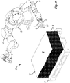
- the invention concerns a gripper 1, which is adapted to be used in an automated system 2 for handling flexible substrates 3 provided in a pile 4.
- the system 2 comprises a two-arm robot 5, which is placed behind said pile 4.
- the robot 5 comprises two arms 6 being bendable or rotatable about a plurality of axis, which is well known in the art and hence not further elucidated.
- the robot 5 further comprises a pair of grippers 1, which can be identical, mirror-inverted or all different and are rotatably arranged on one arm 6 each of the robot 5. In the following the description is limited to just one of the grippers 1, which is one that bears the features of the present invention and is illustrated in detail in the drawings in figs. 2 and 3 .
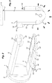
- the gripper 1 shown in fig. 2 comprises a lower finger 7 and an upper finger 8, wherein lower and upper in this case refer to normal use of the gripper 1 when dealing with a substantially flat pile 4, which is horizontally resting on a floor or another leveled base 9 (c.f. fig. 1 ).
- the lower finger 7 comprises a flat bottom face 10, which for a tilting action described below is rising somewhat at 10' towards a fingertip 11, and a flat top plateau 12, which is parallel with the bottom face 10.
- the bottom face 10 and the top plateau 12 both have a basically rectangular shape but converge into a semi-circular shape towards the fingertip 11.
- the bottom face 10 and the top plateau 12 are interconnected by means of wedge structure (to be described in detail below) on all sides except where they meet the arm 6 of the robot 5. Since the top plateau 12 is smaller than the bottom face 10, the wedge structure is slanting from the top plateau 12 towards the bottom face 10 and meets the bottom face 10 along straight lines on sides of the lower finger 7 (mind said basically rectangular shape) and along a curved line along the fingertip 11 (mind said semi-circular shape).
- the upper finger 8 is arranged opposite to the lower finger 7 and movable towards and away from the lower finger 7 by parallel displacement under control of the robot 6.
- the upper finger 8 comprises an essentially dome shaped resilient pad 13, which is arranged exactly opposite to the top plateau 12 of the lower finger 7 and for added flexibility and smooth substrate handling is rotatable about an axis normal to said upper finger 8.
- the lower finger 7 is arranged to be inserted between substrates 3 of the pile 4 by wedging the substrates 3 apart. This is accomplished by means of a first portion of said wedge structure, which comprises a sharp, wedge-shaped edge 14 arranged on one side of the lower finger remote from the fingertip 11. As can be seen, the sharp edge 14 rises from the bottom face 10 of the lower finger 7 towards the top plateau 14 at an acute angle A, which preferably lies within an interval of 5-30°, preferably of 10-25°, and most preferably of 15-20°.
- the gripper 1 As the sharp edge 14 is arranged on a side of the lower finger 7, in order to make it wedge substrates 3 apart the gripper 1 has to be turned by the robot 5, such that the lower finger 7 approaches the pile 4 sideways.
- the second portion of the wedge structure comprises a smooth, wedge-shaped edge 15, which extends along both said sides of the lower finger 7 and runs around the fingertip 11.
- the smooth edge 15 is recessed in relation to the sharp edge 14, but rises to the top plateau 12 at the same angle A as the sharp edge 14 and coplanar with that edge 14.
- the gripper 1 it is possible to turn the gripper 1 in a way that leaves just the smooth edged portion 15 of said wedge structure between the wedged apart substrates 3, the fingertip 11 pointing straight forward into the pile 4.
- the resilient pad 13 of the upper finger 8 is arranged above a top substrate 3 of the pile 4, however not yet tightened. Hence, the lower finger 7 can be displaced sideways along the pile 4 helped by the wedging effect of the smooth edge 15 on the sides and tip 11 of the lower finger 7.
- the gripper 1 is tilted, such that only an edge of said substrate 3 contacts the top plateau 12 of the lower finger 7 in an inner area remote from the finger tip and such that portion 10' of the flat bottom face 10 of the lower finger 7 lies in a substantially horizontal plane.
- the top plateau 12 comprises a wear resistant metal inlay 12' in level with the plateau 12 as such (c.f. fig. 2 ).
- the gripper 1 When the desired position along the pile 4 is reached, if tilted before, the gripper 1 is leveled again. Then the upper finger 8 with its resilient pad 13 is lowered onto said top substrate 3, thus gripping at least one substrate 3 for subsequent handling between the resilient pad 13 of the upper finger 8 and a corresponding resilient inlay 12" of the flat top plateau 12 of the lower finger 7.
- the resilient inlay 12 which is in level with the top plateau 12 as such, and the smooth edge 15 slanting from the top plateau 12 help treating substrates 3 carefully, wherein the resilient inlay 12" and the resilient pad 13 together are able to provide enough friction to enable safe handling even at moderate gripping pressure levels.
- a plurality of first gas nozzles 16 is arranged at the sharp edge 14 in an interface area between the edge 14 and the top plateau 12. These first gas nozzles 16 serve to direct a flow of gas essentially in parallel with and away from the top plateau 14, said gas cushioning contact between the substrates 3 and the sharp edge 14.
- a plurality of second gas nozzles 17 is arranged along at the smooth edge 15 along the fingertip 11.
- the second gas nozzles 17 are directed to blow gas (c.f. arrows G in fig. 3 ) essentially in parallel with and away from the top plateau 12.
- a single gas feed 18 suffices to provide gas to both types of nozzles 16, 17, and it has turned out that ionized air is an excellent choice of gas as it helps further mitigating problems arising due to static electricity. Further, there is obviously no need of blowing gas other than when the gripper 1 is moved in relation to or is releasing at least one substrate 3, wherein such releasing can be further facilitated if the resilient pad 13 of the upper finger 8 is provided with an air bleed duct 19 to safely avoid suction effects.
- the shape of the gripper 1 could be altered into a rectilinear instead of the curved one, and the edges 14, 15, which are shown to be rising from a large bottom face 10 to a small top plateau 12, could instead be undercut if use is made of a small bottom 10 face and a large top plateau 12.
- the resilient inlay 12" of the top plateau 12 can be made rotatable instead of or complementary to the rotatability of the resilient pad 13.
Landscapes
- Engineering & Computer Science (AREA)
- Mechanical Engineering (AREA)
- Robotics (AREA)
- Manipulator (AREA)
- Container, Conveyance, Adherence, Positioning, Of Wafer (AREA)
- Sheets, Magazines, And Separation Thereof (AREA)
- Feeding Of Articles By Means Other Than Belts Or Rollers (AREA)
Priority Applications (1)
| Application Number | Priority Date | Filing Date | Title |
|---|---|---|---|
| PL15769503T PL3122672T3 (pl) | 2014-03-28 | 2015-03-19 | Chwytak |
Applications Claiming Priority (2)
| Application Number | Priority Date | Filing Date | Title |
|---|---|---|---|
| SE1450358A SE538951C2 (sv) | 2014-03-28 | 2014-03-28 | gripdon |
| PCT/SE2015/050318 WO2015147724A1 (en) | 2014-03-28 | 2015-03-19 | Gripper |
Publications (3)
| Publication Number | Publication Date |
|---|---|
| EP3122672A1 EP3122672A1 (en) | 2017-02-01 |
| EP3122672A4 EP3122672A4 (en) | 2017-11-29 |
| EP3122672B1 true EP3122672B1 (en) | 2019-03-13 |
Family
ID=54196072
Family Applications (1)
| Application Number | Title | Priority Date | Filing Date |
|---|---|---|---|
| EP15769503.2A Active EP3122672B1 (en) | 2014-03-28 | 2015-03-19 | Gripper |
Country Status (9)
| Country | Link |
|---|---|
| US (1) | US9844883B2 (tr) |
| EP (1) | EP3122672B1 (tr) |
| JP (1) | JP6588963B2 (tr) |
| DK (1) | DK3122672T3 (tr) |
| ES (1) | ES2720549T3 (tr) |
| PL (1) | PL3122672T3 (tr) |
| SE (1) | SE538951C2 (tr) |
| TR (1) | TR201907624T4 (tr) |
| WO (1) | WO2015147724A1 (tr) |
Families Citing this family (19)
| Publication number | Priority date | Publication date | Assignee | Title |
|---|---|---|---|---|
| US10569422B2 (en) | 2016-01-20 | 2020-02-25 | Soft Robotics, Inc. | End of arm tools for soft robotic systems |
| JP6701007B2 (ja) * | 2016-06-27 | 2020-05-27 | 川崎重工業株式会社 | ワーク保持機構 |
| JP6789705B2 (ja) * | 2016-07-20 | 2020-11-25 | 大和製罐株式会社 | 把持装置 |
| CN107350992A (zh) * | 2017-05-04 | 2017-11-17 | 苏州柔触机器人科技有限公司 | 一种新型柔性夹头及其柔性夹具和柔性夹持笔 |
| JP6588513B2 (ja) * | 2017-09-05 | 2019-10-09 | ファナック株式会社 | ワーク取り出し装置 |
| US11072080B2 (en) * | 2017-11-10 | 2021-07-27 | Soft Robotics, Inc. | End of arm tools for soft robotic systems |
| JP7317374B2 (ja) * | 2017-11-10 | 2023-07-31 | ソフト ロボティクス, インコーポレイテッド | ソフトロボットシステム用のアームの端部ツール |
| KR102259379B1 (ko) * | 2018-01-24 | 2021-06-01 | 주식회사 엘지에너지솔루션 | 배터리 셀의 전극 이송 장치 |
| USD883351S1 (en) * | 2018-05-10 | 2020-05-05 | Robotiq Inc. | Robotic end effector |
| USD900185S1 (en) * | 2019-03-15 | 2020-10-27 | Misty Robotics, Inc. | Accessory port for a robotic device |
| USD891495S1 (en) * | 2019-03-15 | 2020-07-28 | Misty Robotics, Inc. | Plug accessary for a robotic device |
| DE102019116306A1 (de) * | 2019-06-14 | 2020-12-17 | Koenig & Bauer Ag | Substrathandhabungssystem und Verfahren zum Betreiben eines Substrathandhabungssystems |
| DE102019116301A1 (de) * | 2019-06-14 | 2020-12-17 | Koenig & Bauer Ag | Substrathandhabungssystem und Verfahren zum Betreiben eines Substrathandhabungssystems |
| DE102019116302A1 (de) * | 2019-06-14 | 2020-12-17 | Koenig & Bauer Ag | Substrathandhabungssystem und Verfahren zum Betreiben eines Substrathandhabungssystems |
| DE102019116304A1 (de) * | 2019-06-14 | 2020-12-17 | Koenig & Bauer Ag | Substrathandhabungssystem und Verfahren zum Betreiben eines Substrathandhabungssystems |
| US11302134B2 (en) | 2019-07-23 | 2022-04-12 | Japan Cash Machine Co., Ltd. | Automatic bill handling system |
| JP6823117B1 (ja) * | 2019-07-23 | 2021-01-27 | 日本金銭機械株式会社 | 物体搬送装置 |
| FR3104560B1 (fr) * | 2019-12-11 | 2022-03-11 | Faurecia Interieur Ind | Dispositif de préhension d’une couche de matériau |
| DE102020201669A1 (de) | 2020-02-11 | 2021-08-12 | Heidelberger Druckmaschinen Aktiengesellschaft | Vorrichtung zum Bewegen eines Produktstapels mit einem Roboter |
Family Cites Families (16)
| Publication number | Priority date | Publication date | Assignee | Title |
|---|---|---|---|---|
| US3355074A (en) | 1965-03-01 | 1967-11-28 | Proctor Hydro Set Company | System for removing stockings from forms |
| DE2649959C2 (de) | 1976-10-30 | 1985-09-12 | Karl Mohr | Vorrichtung zur Übergabe eines Teilstapels zu beschneidenden Gutes von einem Gesamtstapel in eine Rüttelstation |
| DE2723162A1 (de) | 1977-05-23 | 1978-11-30 | Mohr | Vorrichtung zur uebergabe eines teilstapels bedruckter boegen von einem gesamtstapel in eine ruettelstation |
| JP2597004B2 (ja) * | 1988-05-16 | 1997-04-02 | 株式会社 丸石製作所 | 紙分離装置の紙分離方法 |
| DE3835032A1 (de) * | 1988-10-14 | 1990-04-19 | Niepmann Traylift Transport | Verfahren und vorrichtung zum entstapeln von blockweise auf paletten gestapelten zuschnitten |
| IT217240Z2 (it) * | 1989-04-05 | 1991-11-21 | Euromac Spa | Attrezzo per manipolare pacchi di materiali laminari flessibili, in macchine per la lavorazione del legno e simili |
| CH680126A5 (tr) * | 1989-10-12 | 1992-06-30 | Schneider Engineering | |
| DE4124077C2 (de) * | 1991-07-19 | 1995-03-09 | Fraunhofer Ges Forschung | Einrichtung zur Aufnahme von biegeschlaffen flächigen Teilen |
| IT1279959B1 (it) * | 1995-06-22 | 1997-12-23 | Gd Spa | Dispositivo per il prelievo di pile di prodotti da un supporto |
| US6139253A (en) * | 1998-08-12 | 2000-10-31 | Cuno, Inc. | Lifting device for transporting disk stacks |
| DE19927946C2 (de) | 1999-06-18 | 2001-05-10 | Bell & Howell Co | Greifermechanismus für Einrichtungen zur Handhabung blattartiger oder plattenartiger Gegenstände, insbesondere für Postbearbeitungsmaschinen |
| JP4003004B2 (ja) * | 2002-07-01 | 2007-11-07 | 独立行政法人 国立印刷局 | 用紙分離供給装置 |
| DE502007004027D1 (de) * | 2007-10-24 | 2010-07-15 | Mohr Adolf Maschf | Verfahren zum Auflockern eines aus Blättern gebildeten Stapels, insbesondere eines Papierstapels, sowie Vorrichtung zur Durchführung des Verfahrens |
| DE102010016938B4 (de) * | 2010-05-12 | 2014-06-12 | Baumann Maschinenbau Solms Gmbh & Co. Kg | Vorrichtung und Verfahren zum Abnehmen eines Teilstapels von einem Blätterstapel |
| WO2012069056A1 (en) * | 2010-11-22 | 2012-05-31 | Industrial Robot Automation | Automatic handling and aeration of a stack of paper sheets |
| CA2745476A1 (en) * | 2011-07-06 | 2013-01-06 | Axium Inc. | Depalletizing tool |
-
2014
- 2014-03-28 SE SE1450358A patent/SE538951C2/sv unknown
-
2015
- 2015-03-19 PL PL15769503T patent/PL3122672T3/pl unknown
- 2015-03-19 US US15/129,600 patent/US9844883B2/en active Active
- 2015-03-19 ES ES15769503T patent/ES2720549T3/es active Active
- 2015-03-19 JP JP2017502563A patent/JP6588963B2/ja active Active
- 2015-03-19 TR TR2019/07624T patent/TR201907624T4/tr unknown
- 2015-03-19 WO PCT/SE2015/050318 patent/WO2015147724A1/en active Application Filing
- 2015-03-19 DK DK15769503.2T patent/DK3122672T3/da active
- 2015-03-19 EP EP15769503.2A patent/EP3122672B1/en active Active
Non-Patent Citations (1)
| Title |
|---|
| None * |
Also Published As
| Publication number | Publication date |
|---|---|
| SE1450358A1 (sv) | 2015-09-29 |
| PL3122672T3 (pl) | 2019-08-30 |
| ES2720549T3 (es) | 2019-07-22 |
| JP6588963B2 (ja) | 2019-10-09 |
| WO2015147724A1 (en) | 2015-10-01 |
| DK3122672T3 (da) | 2019-05-13 |
| TR201907624T4 (tr) | 2019-06-21 |
| US9844883B2 (en) | 2017-12-19 |
| EP3122672A1 (en) | 2017-02-01 |
| SE538951C2 (sv) | 2017-02-28 |
| EP3122672A4 (en) | 2017-11-29 |
| JP2017511263A (ja) | 2017-04-20 |
| US20170173800A1 (en) | 2017-06-22 |
Similar Documents
| Publication | Publication Date | Title |
|---|---|---|
| EP3122672B1 (en) | Gripper | |
| JP2017511263A5 (tr) | ||
| CN112770992B (zh) | 真空抓手装置、进给单元和输送扁平部件的方法 | |
| JP6616819B2 (ja) | フレキシブル基板のスタックを処理する方法およびロボットセル | |
| CN203959342U (zh) | 一种装饰石膏板推板分板装置 | |
| US4392766A (en) | Automatic feeding apparatus | |
| CA2655772C (en) | Sheet feeder | |
| EP1637487A3 (en) | Sheet handling apparatus | |
| ES2775180T3 (es) | Aparato y procedimiento para separar y desplazar de forma repetida la bolsa de más arriba de una pila de bolsas | |
| JP2002193463A (ja) | パイルのプレート状のフレキシブルなワークを個別化するための装置 | |
| US11919152B2 (en) | Vacuum gripper, feed unit, and method for conveying flat components | |
| PL1685045T5 (pl) | Usprawniony chwytak zdejmująco-układający | |
| EP3131841A1 (en) | Pre-angling of articles for sortation | |
| CN110402241A (zh) | 玻璃板的制造方法及制造装置 | |
| US9258937B2 (en) | Sod harvester stacking head that is movable with a stacking conveyor | |
| JP2017200837A (ja) | 容器供給装置 | |
| KR20180044275A (ko) | 물품의 방출을 허용 및 차단하기 위한 해제장치 및 물품을 방출시키는 방법 | |
| SE0950751A1 (sv) | Lyftdon med medel för fasthållande och frisläppande av ett föremål | |
| CN205240711U (zh) | 用于抓取和操作物件的装置和系统 | |
| JP2018109678A5 (tr) | ||
| CN107447192A (zh) | 掩膜板卡夹以及掩膜板 | |
| JP2009120289A (ja) | 食品容器供給装置 | |
| DE29916095U1 (de) | Anordnung zum Fördern und Stapeln von überwiegend flachen und flexiblen Gegenständen, insbesondere von Handschuhen | |
| WO2020160240A1 (en) | Automated lifting hook apparatus with guide | |
| KR970001803Y1 (ko) | 구운 김의 자동 절단 적재기 |
Legal Events
| Date | Code | Title | Description |
|---|---|---|---|
| STAA | Information on the status of an ep patent application or granted ep patent |
Free format text: STATUS: THE INTERNATIONAL PUBLICATION HAS BEEN MADE |
|
| PUAI | Public reference made under article 153(3) epc to a published international application that has entered the european phase |
Free format text: ORIGINAL CODE: 0009012 |
|
| STAA | Information on the status of an ep patent application or granted ep patent |
Free format text: STATUS: REQUEST FOR EXAMINATION WAS MADE |
|
| 17P | Request for examination filed |
Effective date: 20160905 |
|
| AK | Designated contracting states |
Kind code of ref document: A1 Designated state(s): AL AT BE BG CH CY CZ DE DK EE ES FI FR GB GR HR HU IE IS IT LI LT LU LV MC MK MT NL NO PL PT RO RS SE SI SK SM TR |
|
| AX | Request for extension of the european patent |
Extension state: BA ME |
|
| DAV | Request for validation of the european patent (deleted) | ||
| DAX | Request for extension of the european patent (deleted) | ||
| A4 | Supplementary search report drawn up and despatched |
Effective date: 20171030 |
|
| RIC1 | Information provided on ipc code assigned before grant |
Ipc: B65H 31/30 20060101ALI20171024BHEP Ipc: B65H 5/14 20060101ALI20171024BHEP Ipc: B25J 9/00 20060101ALI20171024BHEP Ipc: B65H 5/08 20060101ALI20171024BHEP Ipc: B25J 15/02 20060101ALI20171024BHEP Ipc: B65H 3/32 20060101AFI20171024BHEP Ipc: B65H 3/48 20060101ALI20171024BHEP Ipc: B25J 15/00 20060101ALI20171024BHEP |
|
| RIC1 | Information provided on ipc code assigned before grant |
Ipc: B25J 9/00 20060101ALI20180831BHEP Ipc: B65H 5/08 20060101ALI20180831BHEP Ipc: B65H 5/14 20060101ALI20180831BHEP Ipc: B65H 3/32 20060101AFI20180831BHEP Ipc: B25J 15/00 20060101ALI20180831BHEP Ipc: B25J 15/02 20060101ALI20180831BHEP Ipc: B65H 31/30 20060101ALI20180831BHEP Ipc: B65H 3/48 20060101ALI20180831BHEP |
|
| GRAP | Despatch of communication of intention to grant a patent |
Free format text: ORIGINAL CODE: EPIDOSNIGR1 |
|
| STAA | Information on the status of an ep patent application or granted ep patent |
Free format text: STATUS: GRANT OF PATENT IS INTENDED |
|
| INTG | Intention to grant announced |
Effective date: 20181019 |
|
| GRAS | Grant fee paid |
Free format text: ORIGINAL CODE: EPIDOSNIGR3 |
|
| GRAA | (expected) grant |
Free format text: ORIGINAL CODE: 0009210 |
|
| STAA | Information on the status of an ep patent application or granted ep patent |
Free format text: STATUS: THE PATENT HAS BEEN GRANTED |
|
| AK | Designated contracting states |
Kind code of ref document: B1 Designated state(s): AL AT BE BG CH CY CZ DE DK EE ES FI FR GB GR HR HU IE IS IT LI LT LU LV MC MK MT NL NO PL PT RO RS SE SI SK SM TR |
|
| REG | Reference to a national code |
Ref country code: GB Ref legal event code: FG4D |
|
| REG | Reference to a national code |
Ref country code: CH Ref legal event code: EP Ref country code: AT Ref legal event code: REF Ref document number: 1107410 Country of ref document: AT Kind code of ref document: T Effective date: 20190315 |
|
| REG | Reference to a national code |
Ref country code: IE Ref legal event code: FG4D |
|
| REG | Reference to a national code |
Ref country code: DE Ref legal event code: R096 Ref document number: 602015026427 Country of ref document: DE |
|
| REG | Reference to a national code |
Ref country code: DK Ref legal event code: T3 Effective date: 20190507 |
|
| REG | Reference to a national code |
Ref country code: SE Ref legal event code: TRGR |
|
| REG | Reference to a national code |
Ref country code: ES Ref legal event code: FG2A Ref document number: 2720549 Country of ref document: ES Kind code of ref document: T3 Effective date: 20190722 |
|
| REG | Reference to a national code |
Ref country code: NL Ref legal event code: MP Effective date: 20190313 |
|
| REG | Reference to a national code |
Ref country code: LT Ref legal event code: MG4D |
|
| PG25 | Lapsed in a contracting state [announced via postgrant information from national office to epo] |
Ref country code: LT Free format text: LAPSE BECAUSE OF FAILURE TO SUBMIT A TRANSLATION OF THE DESCRIPTION OR TO PAY THE FEE WITHIN THE PRESCRIBED TIME-LIMIT Effective date: 20190313 Ref country code: FI Free format text: LAPSE BECAUSE OF FAILURE TO SUBMIT A TRANSLATION OF THE DESCRIPTION OR TO PAY THE FEE WITHIN THE PRESCRIBED TIME-LIMIT Effective date: 20190313 Ref country code: NO Free format text: LAPSE BECAUSE OF FAILURE TO SUBMIT A TRANSLATION OF THE DESCRIPTION OR TO PAY THE FEE WITHIN THE PRESCRIBED TIME-LIMIT Effective date: 20190613 |
|
| PG25 | Lapsed in a contracting state [announced via postgrant information from national office to epo] |
Ref country code: HR Free format text: LAPSE BECAUSE OF FAILURE TO SUBMIT A TRANSLATION OF THE DESCRIPTION OR TO PAY THE FEE WITHIN THE PRESCRIBED TIME-LIMIT Effective date: 20190313 Ref country code: RS Free format text: LAPSE BECAUSE OF FAILURE TO SUBMIT A TRANSLATION OF THE DESCRIPTION OR TO PAY THE FEE WITHIN THE PRESCRIBED TIME-LIMIT Effective date: 20190313 Ref country code: BG Free format text: LAPSE BECAUSE OF FAILURE TO SUBMIT A TRANSLATION OF THE DESCRIPTION OR TO PAY THE FEE WITHIN THE PRESCRIBED TIME-LIMIT Effective date: 20190613 Ref country code: GR Free format text: LAPSE BECAUSE OF FAILURE TO SUBMIT A TRANSLATION OF THE DESCRIPTION OR TO PAY THE FEE WITHIN THE PRESCRIBED TIME-LIMIT Effective date: 20190614 Ref country code: LV Free format text: LAPSE BECAUSE OF FAILURE TO SUBMIT A TRANSLATION OF THE DESCRIPTION OR TO PAY THE FEE WITHIN THE PRESCRIBED TIME-LIMIT Effective date: 20190313 Ref country code: NL Free format text: LAPSE BECAUSE OF FAILURE TO SUBMIT A TRANSLATION OF THE DESCRIPTION OR TO PAY THE FEE WITHIN THE PRESCRIBED TIME-LIMIT Effective date: 20190313 |
|
| REG | Reference to a national code |
Ref country code: AT Ref legal event code: MK05 Ref document number: 1107410 Country of ref document: AT Kind code of ref document: T Effective date: 20190313 |
|
| PG25 | Lapsed in a contracting state [announced via postgrant information from national office to epo] |
Ref country code: EE Free format text: LAPSE BECAUSE OF FAILURE TO SUBMIT A TRANSLATION OF THE DESCRIPTION OR TO PAY THE FEE WITHIN THE PRESCRIBED TIME-LIMIT Effective date: 20190313 Ref country code: SK Free format text: LAPSE BECAUSE OF FAILURE TO SUBMIT A TRANSLATION OF THE DESCRIPTION OR TO PAY THE FEE WITHIN THE PRESCRIBED TIME-LIMIT Effective date: 20190313 Ref country code: CZ Free format text: LAPSE BECAUSE OF FAILURE TO SUBMIT A TRANSLATION OF THE DESCRIPTION OR TO PAY THE FEE WITHIN THE PRESCRIBED TIME-LIMIT Effective date: 20190313 Ref country code: RO Free format text: LAPSE BECAUSE OF FAILURE TO SUBMIT A TRANSLATION OF THE DESCRIPTION OR TO PAY THE FEE WITHIN THE PRESCRIBED TIME-LIMIT Effective date: 20190313 Ref country code: AL Free format text: LAPSE BECAUSE OF FAILURE TO SUBMIT A TRANSLATION OF THE DESCRIPTION OR TO PAY THE FEE WITHIN THE PRESCRIBED TIME-LIMIT Effective date: 20190313 Ref country code: PT Free format text: LAPSE BECAUSE OF FAILURE TO SUBMIT A TRANSLATION OF THE DESCRIPTION OR TO PAY THE FEE WITHIN THE PRESCRIBED TIME-LIMIT Effective date: 20190713 |
|
| REG | Reference to a national code |
Ref country code: CH Ref legal event code: PL |
|
| PG25 | Lapsed in a contracting state [announced via postgrant information from national office to epo] |
Ref country code: LU Free format text: LAPSE BECAUSE OF NON-PAYMENT OF DUE FEES Effective date: 20190319 Ref country code: SM Free format text: LAPSE BECAUSE OF FAILURE TO SUBMIT A TRANSLATION OF THE DESCRIPTION OR TO PAY THE FEE WITHIN THE PRESCRIBED TIME-LIMIT Effective date: 20190313 |
|
| REG | Reference to a national code |
Ref country code: BE Ref legal event code: MM Effective date: 20190331 |
|
| REG | Reference to a national code |
Ref country code: DE Ref legal event code: R097 Ref document number: 602015026427 Country of ref document: DE |
|
| PG25 | Lapsed in a contracting state [announced via postgrant information from national office to epo] |
Ref country code: AT Free format text: LAPSE BECAUSE OF FAILURE TO SUBMIT A TRANSLATION OF THE DESCRIPTION OR TO PAY THE FEE WITHIN THE PRESCRIBED TIME-LIMIT Effective date: 20190313 Ref country code: IS Free format text: LAPSE BECAUSE OF FAILURE TO SUBMIT A TRANSLATION OF THE DESCRIPTION OR TO PAY THE FEE WITHIN THE PRESCRIBED TIME-LIMIT Effective date: 20190713 |
|
| PLBE | No opposition filed within time limit |
Free format text: ORIGINAL CODE: 0009261 |
|
| STAA | Information on the status of an ep patent application or granted ep patent |
Free format text: STATUS: NO OPPOSITION FILED WITHIN TIME LIMIT |
|
| PG25 | Lapsed in a contracting state [announced via postgrant information from national office to epo] |
Ref country code: LI Free format text: LAPSE BECAUSE OF NON-PAYMENT OF DUE FEES Effective date: 20190331 Ref country code: IE Free format text: LAPSE BECAUSE OF NON-PAYMENT OF DUE FEES Effective date: 20190319 Ref country code: MC Free format text: LAPSE BECAUSE OF FAILURE TO SUBMIT A TRANSLATION OF THE DESCRIPTION OR TO PAY THE FEE WITHIN THE PRESCRIBED TIME-LIMIT Effective date: 20190313 Ref country code: CH Free format text: LAPSE BECAUSE OF NON-PAYMENT OF DUE FEES Effective date: 20190331 |
|
| 26N | No opposition filed |
Effective date: 20191216 |
|
| PG25 | Lapsed in a contracting state [announced via postgrant information from national office to epo] |
Ref country code: SI Free format text: LAPSE BECAUSE OF FAILURE TO SUBMIT A TRANSLATION OF THE DESCRIPTION OR TO PAY THE FEE WITHIN THE PRESCRIBED TIME-LIMIT Effective date: 20190313 Ref country code: BE Free format text: LAPSE BECAUSE OF NON-PAYMENT OF DUE FEES Effective date: 20190331 |
|
| PG25 | Lapsed in a contracting state [announced via postgrant information from national office to epo] |
Ref country code: MT Free format text: LAPSE BECAUSE OF NON-PAYMENT OF DUE FEES Effective date: 20190319 |
|
| REG | Reference to a national code |
Ref country code: DE Ref legal event code: R081 Ref document number: 602015026427 Country of ref document: DE Owner name: YASKAWA NORDIC AB, SE Free format text: FORMER OWNER: YASKAWA NORDIC AB, TORSAS, SE |
|
| REG | Reference to a national code |
Ref country code: DE Ref legal event code: R081 Ref document number: 602015026427 Country of ref document: DE Owner name: YASKAWA NORDIC AB, SE Free format text: FORMER OWNER: YASKAWA EUROPE HOLDING AB, TORSAS, SE |
|
| PG25 | Lapsed in a contracting state [announced via postgrant information from national office to epo] |
Ref country code: CY Free format text: LAPSE BECAUSE OF FAILURE TO SUBMIT A TRANSLATION OF THE DESCRIPTION OR TO PAY THE FEE WITHIN THE PRESCRIBED TIME-LIMIT Effective date: 20190313 |
|
| PG25 | Lapsed in a contracting state [announced via postgrant information from national office to epo] |
Ref country code: HU Free format text: LAPSE BECAUSE OF FAILURE TO SUBMIT A TRANSLATION OF THE DESCRIPTION OR TO PAY THE FEE WITHIN THE PRESCRIBED TIME-LIMIT; INVALID AB INITIO Effective date: 20150319 |
|
| PG25 | Lapsed in a contracting state [announced via postgrant information from national office to epo] |
Ref country code: MK Free format text: LAPSE BECAUSE OF FAILURE TO SUBMIT A TRANSLATION OF THE DESCRIPTION OR TO PAY THE FEE WITHIN THE PRESCRIBED TIME-LIMIT Effective date: 20190313 |
|
| PGFP | Annual fee paid to national office [announced via postgrant information from national office to epo] |
Ref country code: FR Payment date: 20230216 Year of fee payment: 9 Ref country code: DK Payment date: 20230215 Year of fee payment: 9 |
|
| PGFP | Annual fee paid to national office [announced via postgrant information from national office to epo] |
Ref country code: TR Payment date: 20230308 Year of fee payment: 9 Ref country code: SE Payment date: 20230215 Year of fee payment: 9 Ref country code: PL Payment date: 20230320 Year of fee payment: 9 Ref country code: IT Payment date: 20230220 Year of fee payment: 9 |
|
| P01 | Opt-out of the competence of the unified patent court (upc) registered |
Effective date: 20230525 |
|
| PGFP | Annual fee paid to national office [announced via postgrant information from national office to epo] |
Ref country code: ES Payment date: 20230403 Year of fee payment: 9 |
|
| PGFP | Annual fee paid to national office [announced via postgrant information from national office to epo] |
Ref country code: DE Payment date: 20240216 Year of fee payment: 10 Ref country code: GB Payment date: 20240215 Year of fee payment: 10 |