EP3122480B2 - Vorrichtung zur berührungslosen walzenreinigung und verfahren hierfür - Google Patents
Vorrichtung zur berührungslosen walzenreinigung und verfahren hierfür Download PDFInfo
- Publication number
- EP3122480B2 EP3122480B2 EP15711747.4A EP15711747A EP3122480B2 EP 3122480 B2 EP3122480 B2 EP 3122480B2 EP 15711747 A EP15711747 A EP 15711747A EP 3122480 B2 EP3122480 B2 EP 3122480B2
- Authority
- EP
- European Patent Office
- Prior art keywords
- nozzle
- roller
- hood
- disposed
- gas flow
- Prior art date
- Legal status (The legal status is an assumption and is not a legal conclusion. Google has not performed a legal analysis and makes no representation as to the accuracy of the status listed.)
- Active
Links
Images

Classifications
-
- B—PERFORMING OPERATIONS; TRANSPORTING
- B08—CLEANING
- B08B—CLEANING IN GENERAL; PREVENTION OF FOULING IN GENERAL
- B08B5/00—Cleaning by methods involving the use of air flow or gas flow
- B08B5/02—Cleaning by the force of jets, e.g. blowing-out cavities
- B08B5/023—Cleaning travelling work
- B08B5/026—Cleaning moving webs
-
- B—PERFORMING OPERATIONS; TRANSPORTING
- B21—MECHANICAL METAL-WORKING WITHOUT ESSENTIALLY REMOVING MATERIAL; PUNCHING METAL
- B21B—ROLLING OF METAL
- B21B28/00—Maintaining rolls or rolling equipment in effective condition
- B21B28/02—Maintaining rolls in effective condition, e.g. reconditioning
- B21B28/04—Maintaining rolls in effective condition, e.g. reconditioning while in use, e.g. polishing or grinding while the rolls are in their stands
-
- B—PERFORMING OPERATIONS; TRANSPORTING
- B08—CLEANING
- B08B—CLEANING IN GENERAL; PREVENTION OF FOULING IN GENERAL
- B08B2203/00—Details of cleaning machines or methods involving the use or presence of liquid or steam
- B08B2203/02—Details of machines or methods for cleaning by the force of jets or sprays
- B08B2203/0229—Suction chambers for aspirating the sprayed liquid
-
- B—PERFORMING OPERATIONS; TRANSPORTING
- B21—MECHANICAL METAL-WORKING WITHOUT ESSENTIALLY REMOVING MATERIAL; PUNCHING METAL
- B21B—ROLLING OF METAL
- B21B1/00—Metal-rolling methods or mills for making semi-finished products of solid or profiled cross-section; Sequence of operations in milling trains; Layout of rolling-mill plant, e.g. grouping of stands; Succession of passes or of sectional pass alternations
- B21B1/22—Metal-rolling methods or mills for making semi-finished products of solid or profiled cross-section; Sequence of operations in milling trains; Layout of rolling-mill plant, e.g. grouping of stands; Succession of passes or of sectional pass alternations for rolling plates, strips, bands or sheets of indefinite length
- B21B2001/228—Metal-rolling methods or mills for making semi-finished products of solid or profiled cross-section; Sequence of operations in milling trains; Layout of rolling-mill plant, e.g. grouping of stands; Succession of passes or of sectional pass alternations for rolling plates, strips, bands or sheets of indefinite length skin pass rolling or temper rolling
Definitions
- abrasion inevitably occurs, both from the rollers themselves and from the strip surface.
- a common method is to remove it by spraying on a liquid such as water, emulsion or similar. In this case, it is referred to as wet rolling or skin-passing.
- rolling or skin-passing can also be carried out without liquid. In this case, it is referred to as dry rolling or skin-passing.
- roller cleaning For dry rolling or skin-passing, mechanical, contact methods are used in the state of the art for roller cleaning, such as brushes and scraper blades, which remove adhering particles or rolled-on dirt deposits from the roller surface.
- Conventional cleaning systems such as brushes are based on a contact principle. Due to wear and tear, these often have to be replaced and cleaned and lead to abrasive wear on the roller surface. Roller cleaning using contact systems is therefore disruptive and maintenance-intensive.
- the solutions contained in the state of the art are also difficult to retrofit into existing rolling or skin-passing stands and are wear-intensive in daily use. As a result, these systems are associated with relatively high operating costs in addition to the investment costs.
- a generic system and a generic process are EP 0 916 416 A2 known.
- the invention is based on the object of providing a device and a method for cleaning rolls, in particular support and/or work rolls of a strip processing plant, in particular rolling or skin-pass stands. Especially for dry rolling or skin-passing.
- the disadvantages of the solutions known from the prior art high wear, maintenance-intensive, complex designs, Certainly must be avoided.
- a skin-pass or rolling mill typically consists of a pair of work rolls, which are in direct contact with the strip surface, and a pair of support rolls (so-called four-high mill) or a system of several support rolls (e.g. six-high skin-pass mill or other systems), which stabilize and drive the work rolls.
- the device or method according to the invention is used for the continuous cleaning of rolls using a combined suction and blowing device.
- a combined suction and blowing device By constantly blowing onto the roll surface, the abrasion that occurs during rolling is continuously removed, thus preventing the formation of a layer of dirt on the roll surface.
- the rolling dust By combining it with an integrated suction system, the rolling dust can be removed directly. This eliminates the need for a complete enclosure of the rolling mill or skin-pass stand.
- the hood and the effective area of the blown-in gas or fluid flow covers the entire working width of the roller to be cleaned, which corresponds at least to the width of the metal strip.
- the blowing air is therefore ideally sprayed via a slot nozzle or a nozzle bar made up of several individual nozzles, which extend in the width direction of the roller at least over the width of the strip material. From an economic point of view, air or compressed air is ideally used as the gas.
- the incoming air flow must be dimensioned in such a way that the particles adhering to the roller surface are detached.
- the shape of the nozzle is also particularly important here.
- the nozzle is designed in the form of a Venturi nozzle, which allows the amount and speed of the gas flow to be increased.
- the geometry of the nozzle is designed in such a way that the gas flow is concentrated on the surface by using the Coanda effect.
- the flow in the hood must be designed in such a way that no so-called dead zones occur within the hood, which encourage the skin pass dust to settle on the wall of the suction hood.
- rounded edges and transitions and/or continuously flowing surfaces ensure that the flow conditions are as laminar as possible, i.e. largely free of turbulence.
- the suction of the hood must be set in such a way that the skin pass dust can be completely removed from the hood.
- the supply and exhaust air must be adjusted so that no excess pressure is created in the hood, which would throw particles out of the gap between the hood and the roller surface.
- An embodiment of the invention for cleaning a roll of a rolling mill or skin-pass mill for the dry rolling or skin-passing of metal strips of a plant for processing strip-shaped material is described below, wherein at least one nozzle is provided which directs a fluid flow onto the surface of the roll, and at least one suction channel is provided.
- the at least one nozzle and the at least one suction channel are arranged in a common hood, wherein the hood covers part of the circumference of the roller.
- the extraction capacity, i.e. the volume flow, of the at least one extraction channel arranged in the hood is greater than the fluid flow introduced by means of the at least one nozzle arranged in the hood.
- the volume flow of the exhaust air is therefore set to be 5% to 50% greater than the gas flow blown in.
- the at least one nozzle covers at least a width of the roller corresponding to the width of the strip-shaped material.
- the at least one nozzle is directed at an angle of +/- 45°, preferably +/- 10°, in particular 0°, relative to the perpendicular to the surface of the roller and is arranged at a distance of less than 50 mm, preferably 1 mm to 30 mm, from the surface of the roller.
- the at least one nozzle is designed as a slot nozzle or as a nozzle bar with several individual nozzles arranged next to one another, whereby the individual nozzles themselves can be point-shaped or slot-shaped.
- the maximum nozzle spacing depends on the nozzle opening and shape and the resulting flow speed. For a nozzle with a 4 mm opening, it is approximately 50 mm. A particularly good cleaning effect is achieved with nozzle spacings that are approximately 1-30 mm from the roller surface.
- means are provided in the at least one nozzle or its feed line to at least temporarily introduce abrasive particles into the gas flow.
- abrasive particles for example, corundum-based particles known from the field of jet processing.
- the cleaning device according to the invention is adjustably mounted on the roll stand.
- At least one further suction channel is provided, which preferably extends over a width corresponding to the width of the strip-shaped material and is arranged outside the hood in the region of the contact point, preferably in the exit direction, with an adjacent roller or the strip-shaped material.
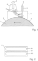
- a roller (1) with a dirt coating (3) adhering to the roller surface (2) is shown.
- a hood (4) according to the invention is moved up to the roller surface (2), whereby this does not touch the roller surfaces (2).
- the hood (4) at least one nozzle (5) is provided in the width direction, from which a gas stream (6) is blown at a speed of more than 20 m/s, preferably more than 40 m/s, onto the roller surface (2) with the dirt coating (3).
- speeds of more than 500 m/s are no longer sensible.
- speeds of less than 300 m/s are preferred for reasons of noise protection.
- the gas stream (6) causes the dirt coating (3) to detach from the roller surface (2) and the particles (7) formed are sucked away with the exhaust air (9) through at least one suction channel (8).
- the volume flow of the exhaust air (9) is dimensioned such that that it is greater than the volume of the gas stream (6) supplied via the at least one nozzle (5).
- Fig. 2 represents a hood (4) as seen from the direction of the roller surface, wherein the at least one nozzle (5) is designed as a slot nozzle (5.1).
- slot nozzles (5.1) or flat slot nozzles are known as air knives.
- the slot nozzle (5.1) extends over the width of the hood (4) and is provided approximately in the middle in one embodiment.
- two suction channels (8) are provided on the hood (4), wherein the first suction channel (8.1), as seen from the direction of rotation of the roller, is located in front of the slot nozzle (5.1) and extends over a large part of the width of the hood (4).
- a second suction channel (8.2) is provided on the trailing side of the slot nozzle (5.1) as seen in the direction of rotation of the roller.
- the Fig. 2 The symmetrical structure shown is not mandatory, but offers the advantage that installation can be carried out regardless of the direction of rotation.
- the suction channels (8) can also consist of several individual suction channels arranged next to one another.
- the in Fig. 3 The embodiment shown is also viewed from the direction of the roller surface.
- the at least one nozzle (5) is designed in the form of a nozzle bar (5.2) which consists of a large number of individual nozzles arranged next to one another in the width direction.
- additional individual nozzles (5.3) are provided, through which the dirt coating (3) is broken up before the nozzle bar (5.2), whereby the cleaning effect can be further improved.
- Several suction channels (8.3) are provided in front of and between the additional individual nozzles (5.3).
- a second suction channel (8.2) is provided.
- the second suction channel (8.2) does not have to be designed as a single channel extending approximately over the width of the hood (4), as shown, but can also be divided into several individual suction channels (8.3).
- Fig. 4 shows a schematic view of a rolling mill with two working rolls (1.1) between which the strip material (10) to be processed passes.
- the working rolls (1.1) are supported by a pair of support rolls (1.2).
- the hoods (4) can be provided on both the working rolls (1.1) and the support rolls (1.2).
- the arrangement of the hoods (4) and thus the cleaning of the working rolls (1.1) preferably takes place on the inlet side of the strip (10).
- further suction channels (11) are provided for suctioning free particles.
- the further suction channel (11) preferably has a width that corresponds to the width of the strip-shaped material and is arranged in the area of the contact point of the work roll (1.1) with the strip (10) in the exit direction.
- Further suction channels (11) can additionally or alternatively be arranged near the contact points between the work roll (1.1) and the support roll (1.2) or between support rolls (1.2).
Landscapes
- Engineering & Computer Science (AREA)
- Mechanical Engineering (AREA)
- Cleaning In General (AREA)
Description
- Beim Walzen und Dressieren von Metallen, insbesondere von Metallbändern, beispielsweise aus Stahl, Aluminium, Magnesium oder weiteren Nichteisenmetallen, entsteht unvermeidlich Abrieb, sowohl von den Walzen selbst, als auch von der Bandoberfläche. Damit dieser Abrieb keine Qualitätsmängel auf der Bandoberfläche z.B. durch Verschmutzung oder Abdrücke erzeugt, muss dieser entfernt werden. Ein übliches Verfahren ist die Entfernung durch Aufsprühen einer Flüssigkeit, wie Wasser, Emulsion, oder dgl. In diesem Fall spricht man von Nasswalzen bzw. -dressieren. Als Alternative insbesondere für spezielle Produkt- und Qualitätsanforderungen, z.B. bei besonders korrosionsgefährdeten Produkten, kann jedoch auch ohne Flüssigkeit gewalzt bzw. dressiert werden. In diesem Fall spricht man von Trockenwalzen bzw. -dressieren.
- Für Trockenwalzen bzw. -dressieren werden zur Walzenreinigung im Stand der Technik mechanische, berührende Methoden eingesetzt, wie Bürsten und Schaberklingen, die anhaftende Partikel bzw. festgewalzten Schmutzbelag von der Walzenoberfläche entfernen. Konventionelle Reinigungssysteme wie Bürsten basieren auf einem berührenden Wirkprinzip. Aus Verschleißgründen müssen diese oft getauscht und gereinigt werden und führen zu einem abrasiven Verschleiß der Walzenoberfläche. Somit ist eine Walzenreinigung durch berührende Systeme störungs- und wartungsintensiv. Die im Stand der Technik enthaltenen Lösungen sind zudem schwierig in bereits bestehende Walz- bzw. Dressiergerüste nachrüstbar und verschleißintensiv im täglichen Gebrauch. Somit sind diese Systeme neben den Investitionskosten auch mit relativen hohen Betriebskosten verbunden. Eine gattungsgemässe Anlage sowie ein gattungsgemässes Verfahren sind aus
EP 0 916 416 A2 bekannt. Der Erfindung liegt die Aufgabe zugrunde eine Vorrichtung sowie ein Verfahren zum Reinigen von Walzen, insbesondere von Stütz- und/oder Arbeitswalzen einer Bandbearbeitungsanlage, insbesondere von Walz- oder Dressiergerüsten, bereitzustellen. Speziell für Trockenwalzen bzw. -dressieren. Hierbei gilt es insbesondere die Nachteile der aus dem Stand der Technik bekannten Lösungen (hoher Verschleiß, wartungsintensiv, komplexe Bauformen, ...) zu vermeiden. - Ein Dressier- oder Walzgerüst besteht typischerweise aus einem Paar Arbeitswalzen, welche mit der Bandoberfläche in direktem Kontakt stehen und einem Stützwalzenpaar (sogenanntes Quartogerüst) oder einem System von mehreren Stützwalzen (z.B. Six-High-Dressiergerüst oder sonstige Systeme), welche die Arbeitswalzen stabilisieren und antreiben.
- Während des Trockenwalzens bzw. -dressierens kommt es zu einem massiven Staubniederschlag ("Flitter" oder "Dressierstaub"), insbesondere aus Abrieb vom Bandmaterial und den Arbeitswalzen, welcher das Aufwachsen einer Schmutzschicht an der Walzenoberfläche vor allem an den Stützwalzen bewirkt. Diese Schmutzschicht kann abplatzen oder auf die Arbeitswalzen übertragen werden, wodurch es zu Eindrücken auf der Bandoberfläche kommt.
- Die erfindungsgemäße Vorrichtung bzw. das erfindungsgemäße Verfahren dient zur kontinuierlichen Reinigung von Walzen durch eine kombinierte Saug-Blas-Vorrichtung. Durch ein permanentes Anblasen der Walzenoberfläche wird der während des Walzens entstehende Abrieb kontinuierlich abgetragen und so die Bildung einer Schmutzschicht auf der Walzenoberfläche unterbunden. Durch die Kombination mit einer integrierten Absaugung kann der Walzstaub unmittelbar abgeführt werden. Eine Kompletteinhausung des Walz- bzw. Dressiergerüstes entfällt hierdurch.
- Sowohl das Anblasen der Walzenoberfläche als auch die Absaugung des Staubes ("Flitters") finden innerhalb einer gemeinsamen Einhausung (Haube) statt, die nah an die zu reinigende Oberfläche positioniert wird, diese allerdings nicht berührt.
- Die Haube sowie der Wirkbereich des eingeblasenen Gas- bzw. Fluidstroms (Blasluft) deckt die komplette Arbeitsbreite der zu reinigenden Walze ab, welche mindestens der Breite des Metallbandes entspricht. Die Blasluft wird daher idealerweise über eine Schlitzdüse oder einen Düsenbalken aus mehreren Einzeldüsen aufgestrahlt, welche sich in Breitenrichtung der Walze mindestens über die Breite des Bandmaterials erstrecken. Als Gas wird aus ökonomischer Sicht idealerweise Luft bzw. Druckluft verwendet.
- Für einen optimalen Betrieb ist eine genauere Betrachtung der ein- und auslaufenden Strömungen ausschlaggebend. So muss der eingehende Luftstrom so dimensioniert werden, dass es zu einem Ablösen der an der Walzenoberfläche anhaftenden Partikel kommt. Hierbei kommt auch der Düsenform eine besondere Bedeutung zu. Die Düse ist in einem Ausführungsbeispiel in Form einer Venturidüse ausgeführt, wodurch sich die Menge bzw. Geschwindigkeit des Gasstroms erhöhen lässt. In einem weiteren Ausführungsbeispiel ist die Geometrie der Düse derart ausgebildet, dass durch die Nutzung des Coanda-Effekts der Gasstrom konzentriert auf die Oberfläche gelenkt wird.
- Die Strömung in der Haube muss so gestaltet werden, dass innerhalb der Haube keine sogenannten Todzonen auftreten, die eine Ablagerung des Dressierstaubes an der Wand der Saughaube begünstigen. Allgemein werden durch gerundete Kanten und Übergänge und/oder fließende kontinuierlich Flächen möglichst laminare Strömungsverhältnisse, d.h. weitgehend turbulenzfrei, gewährleistet. Weiterhin muss die Absaugung der Haube so eingestellt werden, dass der Dressierstaub vollständig aus der Haube entfernt werden kann.
- Zu- und Abluft müssen dabei so eingestellt werden, dass kein Überdruck in der Haube entsteht, welcher Partikel aus dem Spalt zwischen Haube und Walzenoberfläche schleudert.
- Folgend wird eine Ausführungsform der Erfindung zum Reinigen einer Walze eines Walz- oder Dressiergerüsts für das Trockenwalzen bzw. -dressieren von Metallbändern einer Anlage zur Bearbeitung von bandförmigem Material beschrieben, wobei zumindest eine Düse vorgesehen ist, die einen Fluidstrom auf die Oberfläche der Walze richtet, und zumindest ein Absaugkanal vorgesehen ist.
- Die zumindest eine Düse und der zumindest eine Absaugkanal sind in einer gemeinsamen Haube angeordnet, wobei die Haube einen Teil des Umfangs der Walze überdeckt.
- Die Absaugleistung, d.h. der Volumenstrom, des zumindest einen in der Haube angeordneten Absaugkanals ist größer als der mittels der zumindest einen in der Haube angeordneten Düse eingebrachte Fluidstrom. In einer bevorzugten Ausführungsform wird daher der Volumenstrom der Abluft um 5% bis 50% größer als der eingeblasene Gasstrom eingestellt.
- Die zumindest eine Düse überdeckt zumindest eine der Breite des bandförmigen Materials entsprechenden Breite der Walze. Die zumindest eine Düse ist in einem Winkel von +/- 45°, vorzugsweise +/- 10°, insbesondere 0°, gegenüber der senkrechten auf die Oberfläche der Walze gerichtet und in einem Abstand von weniger als 50mm, vorzugsweise 1 mm bis 30mm, von der Oberfläche der Walze entfernt angeordnet.
- Um die Breite abzudecken ist die zumindest eine Düse als Schlitzdüse oder als Düsenbalken mit mehreren nebeneinander angeordneten Einzeldüsen ausgebildet, wobei die Einzeldüsen selbst Punkt- oder schlitzförmig ausgebildet sein können.
- Der Fluid- bzw. Gasstrom tritt mit einer Geschwindigkeit von mindestens 20m/s, vorzugsweise mehr als 40m/s, aus der zumindest einen Düse aus. Der maximale Düsenabstand ist abhängig von der Düsenöffnung und -form und der daraus resultierenden Strömungsgeschwindigkeit. Er beträgt für eine Düse mit einer 4mm-Öffnung ca. 50mm. Eine besonders gute Reinigungswirkung wird bei Düsenabständen erzielt, die ca. 1-30 mm von der Walzenoberfläche entfernt sind.
- Um die Reinigungswirkung weiter zu steigern, sind in einem Ausführungsbeispiel in die zumindest eine Düse oder deren Zuleitung Mittel vorgesehen, um zumindest zeitweise abrasive Partikel in den Gasstrom einzubringen. Beispielsweise aus dem Bereich der Strahlbearbeitung bekannte Partikel auf Korundbasis.
- Zu Wartungszwecken sowie Walzenwechsel und zur Anpassung an unterschiedliche Walzendurchmesser ist die erfindungsgemäße Reinigungsvorrichtung verstellbar am Walzgerüst angebracht.
- In einer weiteren Ausführungsform ist zumindest ein weiterer Absaugkanal vorgesehen, welcher sich vorzugsweise über eine Breite die der Breite des bandförmigen Materials entspricht erstreckt und außerhalb der Haube im Bereich der Kontaktstelle, vorzugsweise in Austrittsrichtung, mit einer benachbarten Walze oder dem bandförmigen Material angeordnet ist.
- Weitere Einzelheiten und Merkmale der Erfindung ergeben sich aus den Zeichnungen und folgend Beschreibung anhand der schematischen Darstellungen. Die Figuren stellen lediglich schematisch beispielhaften Ausführungsformen dar. Gleiche Teile sind mit gleichen Bezugsziffern bezeichnet.
-
Fig. 1 zeigt eine erfindungsgemäße Reinigungsvorrichtung in Richtung der Walzenbreite gesehen. -
Fig. 2 zeigt eine weitere erfindungsgemäße Reinigungsvorrichtung aus Richtung der Walzenoberfläche gesehen. -
Fig. 3 zeigt eine weitere erfindungsgemäße Reinigungsvorrichtung aus Richtung der Walzenoberfläche gesehen. -
Fig. 4 zeigt ein Walzgerüst mit erfindungsgemäßen Reinigungsvorrichtungen. -
- 1
- Walze
- 1.1
- Arbeitswalze
- 1.2
- Stützwalze
- 2
- Walzenoberfläche
- 3
- Schmutzbelag
- 4
- Haube
- 5
- Düse
- 5.1
- Schlitzdüse
- 5.2
- Düsenbalken
- 5.3
- Einzeldüse
- 6
- Gasstrom
- 7
- Partikel
- 8
- Absaugkanal
- 8.1
- erster Absaugkanal
- 8.2
- zweiter Absaugkanal
- 8.3
- einzelner Absaugkanal
- 9
- Abluft
- 10
- Bandmaterial
- 11
- Weiterer Absaugkanal
- In
Fig. 1 ist eine Walze (1) mit an der Walzenoberfläche (2) anhaftenden Schmutzbelag (3) dargestellt. An die Walzenoberfläche (2) ist eine erfindungsgemäße Haube (4) herangefahren, wobei diese die Walzenoberflächen (2) nicht berührt. In der Haube (4) ist in Breitenrichtung zumindest eine Düse (5) vorgesehen, aus welcher ein Gasstrom (6) mit einer Geschwindigkeit von mehr als 20m/s, vorzugsweise mehr als 40m/s, auf die Walzenoberfläche (2) mit dem Schmutzbelag (3) aufgeblasen wird. Aus wirtschaftlicher Sicht sind Geschwindigkeiten über 500m/s nicht mehr sinnvoll. Des Weiteren sind aus Gründen des Lärmschutzes Geschwindigkeiten unter 300m/s bevorzugt. Durch den Gasstrom (6) löst sich der Schmutzbelag (3) von der Walzenoberfläche (2) und die entstandenen Partikel (7) werden durch zumindest einen Absaugkanal (8) mit der Abluft (9) abgesaugt. Der Volumenstrom der Abluft (9) ist dabei so bemessen, dass er größer als der über die zumindest eine Düse (5) zugeführte Volumen des Gasstroms (6) ist. -
Fig. 2 stellt eine Haube (4) aus Richtung der Walzenoberfläche gesehen dar, wobei die zumindest eine Düse (5) als Schlitzdüse (5.1) ausgeführt ist. Derartige Schlitzdüsen (5.1) oder Flachschlitzdüsen sind als Luftmesser bzw. Airknife bekannt. Die Schlitzdüse (5.1) erstreckt sich über die Breite der Haube (4) und ist in einer Ausführungsform ungefähr mittig vorgesehen. In der dargestellten Ausführungsform sind an der Haube (4) zwei Absaugkanäle (8) vorgesehen, wobei sich der erste Absaugkanal (8.1), aus Drehrichtung der Walze gesehen, vor der Schlitzdüse (5.1) befindet und sich über einen Großteil der Breite der Haube (4) erstreckt. Zusätzlich ist ein zweiter Absaugkanal (8.2) auf in Drehrichtung der Walze gesehen nachlaufender Seite der Schlitzdüse (5.1) vorgesehen. Der inFig. 2 gezeigte symmetrische Aufbau ist jedoch nicht zwingend, bietet allerdings den Vorteil, dass der Einbau unabhängig von der Drehrichtung erfolgen kann. - In einer weiteren Ausführungsform ist nur einer der beiden Absaugkanäle (8.1 oder 8.2) vorgesehen. Hierdurch lässt sich eine kleinere Baugröße der Haube (4) realisieren, was den Einbau und Verfahrbarkeit der Haube (4) vereinfacht. Die Absaugkanäle (8) können anstelle der gezeigten Breite auch aus mehreren einzelnen nebeneinander angeordneten Absaugkanälen bestehen.
- Die in
Fig. 3 dargestellte Ausführungsform ist ebenfalls aus Richtung der Walzenoberfläche betrachtet. Hierbei ist die zumindest eine Düse (5) jedoch in Form eines Düsenbalkens (5.2) ausgebildet, der in Breitenrichtung aus einer Vielzahl nebeneinander angeordneter Einzeldüsen besteht. Auf der in Drehrichtung vorlaufenden Seite des Düsenbalkens (5.2) sind weitere zusätzliche Einzeldüsen (5.3) vorgesehen, durch die der Schmutzbelag (3) bereits vor dem Düsenbalken (5.2) aufgebrochen wird, wodurch sich die Reinigungswirkung weiter verbessern lässt. Vor und zwischen den zusätzlichen Einzeldüsen (5.3) sind mehrere Absaugkanäle (8.3) vorgesehen. Nach dem Düsenbalken (5.2) ist wie beim inFig. 2 gezeigten Ausführungsbeispiel ein zweiter Absaugkanal (8.2) vorgesehen. Selbstverständlich muss der zweite Absaugkanal (8.2) nicht wie dargestellt als ein einzelner sich in etwa über die Breite der Haube (4) erstreckender Kanal ausgeführt sein, sondern kann auch in mehrere einzelne Absaugkanäle (8.3) aufgeteilt sein. -
Fig. 4 zeigt schematisch ein Walzgerüst mit zwei Arbeitswalzen (1.1) zwischen denen da zu bearbeitende Bandmaterial (10) durchläuft. Die Arbeitswalzen (1.1) werden durch ein Paar Stützwalzen (1.2) abgestützt. Bei der erfindungsgemäßen Vorrichtung können die Hauben (4) sowohl an den Arbeitswalzen (1.1) als auch an den Stützwalzen (1.2) vorgesehen sein. In Anbetracht der Qualitätsanforderungen erfolgt die Anordnung der Hauben (4) und somit die Reinigung an den Arbeitswalzen (1.1) vorzugsweise an der Einlaufseite der Bandes (10). - In einer weiteren Ausführungsform sind weitere Absaugkanäle (11) zur Absaugung freier Partikel vorgesehen. Der weitere Absaugkanal (11) weist vorzugsweise eine Breite, die der Breite des bandförmigen Materials entspricht, auf und ist im Bereich der Kontaktstelle der Arbeitswalze (1.1) mit dem Band (10) in Austrittsrichtung angeordnet. Weitere Absaugkanäle (11) können zusätzlich oder alternativ in der Nähe der Kontaktstellen zwischen Arbeits- (1.1) und Stützwalze (1.2) bzw. zwischen Stützwalzen (1.2) angeordnet sein.
Claims (16)
- Anlage zur Bearbeitung von bandförmigem Material (10) umfassend eine Walze (1; 1.1; 1.2) eines Walz- oder Dressiergerüsts für das Trockenwalzen beziehungsweise - dressieren von Metallbändern sowie eine Vorrichtung zum Reinigen der Walze (1; 1.1; 1.2), bei der zumindest eine Düse (5; 5.1; 5.2; 5.3), die einen Gasstrom (6) auf die Oberfläche (2) der Walze (1; 1.1; 1.2) richtet, und zumindest ein Absaugkanal (8; 8.1; 8.2; 8.3) vorgesehen ist, bei der die zumindest eine Düse (5; 5.1; 5.2; 5.3) zumindest eine der Breite des bandförmigen Materials (10) entsprechenden Breite der Walze (1; 1.1; 1.2) überdeckt und in einem Winkel von +/-45° gegenüber der Senkrechten auf die Oberfläche (2) der Walze (1; 1.1; 1.2) angeordnet ist, dadurch gekennzeichnet, dass die zumindest eine Düse (5; 5.1; 5.2; 5.3) und zumindest ein Absaugkanal (8; 8.1; 8.2; 8.3) in einer Haube (4) angeordnet ist, dass die Haube (4) einen Teil des Umfangs der Walze (1; 1.1; 1.2) überdeckt, und dass die zumindest eine Düse (5; 5.1; 5.2; 5.3) in einem Abstand von weniger als 50mm von der Oberfläche (2) der Walze (1; 1.1; 1.2) entfernt angeordnet ist.
- Anlage nach Anspruch 1, dadurch gekennzeichnet, dass die Absaugleistung des zumindest einen in der Haube (4) angeordneten Absaugkanals (8; 8.1; 8.2; 8.3) größer als der mittels der zumindest einen in der Haube (4) angeordneten Düse (5; 5.1; 5.2; 5.3) eingebrachte Gasstrom (6) ist.
- Anlage nach einem der Ansprüche 1 oder 2, dadurch gekennzeichnet, dass die zumindest eine Düse (5) als Schlitzdüse (5.1) oder als Düsenbalken (5.2) mit mehreren nebeneinander angeordneten Einzeldüsen (5.3) ausgebildet ist.
- Anlage nach einem der Ansprüche 1 bis 3, dadurch gekennzeichnet, dass der Gasstrom (6) mit einer Geschwindigkeit von mindestens 20m/s, vorzugsweise mehr als 40m/s, aus der zumindest einen Düse (5; 5.1; 5.2; 5.3) austritt und dass der Gasstrom (6) aus Luft besteht.
- Anlage nach einem der Ansprüche 1 bis 4, dadurch gekennzeichnet, dass zumindest eine weitere Düse (5.3) vorgesehen ist, die in Drehrichtung der Walze (1; 1.1; 1.2) gesehen vorzugsweise vor der zumindest einen Düse (5; 5.1; 5.2; 5.3) angeordnet ist.
- Anlage nach einem der Ansprüche 1 bis 5, dadurch gekennzeichnet, dass in die Zuführleitung der zumindest einen Düse (5; 5.1; 5.2; 5.3) und/oder die zumindest eine Düse (5; 5.1; 5.2; 5.3) abrasive Partikel zuführbar sind.
- Anlage nach einem der Ansprüche 1 bis 6, dadurch gekennzeichnet, dass zumindest die Innenflächen der Haube (4) nur gerundete Übergänge untereinander und/oder kontinuierliche Flächen aufweist.
- Anlage nach einem der Ansprüche 1 bis 7, dadurch gekennzeichnet, dass die zumindest eine Düse (5; 5.1; 5.2; 5.3) senkrecht auf die Walzenoberfläche (2) und in einen Abstand von 1mm bis 30mm. von der Walzenoberfläche (2) entfernt angeordnet ist.
- Anlage nach einem der Ansprüche 1 bis 8, dadurch gekennzeichnet, dass zumindest ein weiterer Absaugkanal (11), vorzugsweise über eine Breite die der Breite des bandförmigen Materials (10) entspricht, außerhalb der Haube (4) im Bereich der Kontaktstelle, vorzugsweise in Austrittsrichtung, mit einer benachbarten Walze (1; 1.1; 1.2) oder dem bandförmigen Material (10) angeordnet ist.
- Verfahren zum Reinigen einer Walze (1; 1.1; 1.2) eines Walz- oder Dressiergerüsts für das Trockenwalzen beziehungsweise -dressieren von Metallbändern einer Anlage zur Bearbeitung von bandförmigen Material (10) bei der mittels zumindest einer Düse (5; 5.1; 5.2; 5.3) ein Gasstrom (6) auf die Oberfläche (2) der Walze (1; 1.1; 1.2) gerichtet wird und mittels der zumindest einen Düse (5; 5.1; 5.2; 5.3) der Gasstrom (6) zumindest über eine der Breite des bandförmigen Materials (10) entsprechenden Breite der Walze (1; 1.1; 1.2), in einem Winkel von +/- 45° gegenüber der senkrechten auf die Oberfläche (2) der Walze (1; 1.1; 1.2) aufgestrahlt wird, gekennzeichnet dadurch, dass mittels zumindest eines Absaugkanals (8; 8.1; 8.2; 8.3) Flitter und gelöste Verunreinigungen abgezogen werden, dass die zumindest eine Düse (5; 5.1; 5.2; 5.3) und der zumindest eine Absaugkanal (8; 8.1; 8.2; 8.3) in einer Haube (4) angeordnet wird, dass die Haube (4) einen Teil des Umfangs der Walze (1; 1.1; 1.2) überdeckt, und dass mittels der zumindest einen Düse (5; 5.1; 5.2; 5.3) der Gasstrom (6) in einem Abstand von weniger als 50mm von der Oberfläche (2) der Walze (1; 1.1; 1.2) entfernt aufgestrahlt wird.
- Verfahren nach Anspruch 10, dadurch gekennzeichnet, dass mittels des zumindest einen in der Haube (4) angeordneten Absaugkanals (8; 8.1; 8.2; 8.3) ein größerer Volumenstrom (9) als der mittels der zumindest einen in der Haube (4) angeordneten Düse (5; 5.1; 5.2; 5.3) eingebrachte Gasstrom (6) abgesaugt wird.
- Verfahren nach einem der Ansprüche 10 oder 11, dadurch gekennzeichnet, dass der Gasstrom (6) mit einer Geschwindigkeit von mindestens 20m/s, vorzugsweise mehr als 40m/s, aus der zumindest einen Düse (5; 5.1; 5.2; 5.3) aufgeblasen wird und dass als Fluid des Gasstroms (6) Luft verwendet wird.
- Verfahren nach einem der Ansprüche 10 bis 12, dadurch gekennzeichnet, dass durch zumindest eine weitere Düse (5.3), die in Drehrichtung der Walze (1; 1.1; 1.2) gesehen vor der zumindest einen Düse (5; 5.1; 5.2; 5.3) angeordnet wird, zusätzlich zumindest ein weiterer punktueller Gasstrom (6) aufgeblasen wird.
- Verfahren nach einem der Ansprüche 10 bis 13, dadurch gekennzeichnet, dass dem zumindest einem Gasstrom (6) zumindest zeitweise abrasive Partikel zugeführt werden.
- Verfahren nach einem der Ansprüche 10 bis 14, dadurch gekennzeichnet, dass die zumindest eine Düse (5; 5.1; 5.2; 5.3) senkrecht auf die Walzenoberfläche (2) und in einen Abstand von 1mm bis 30mm von der Walzenoberfläche (2) entfernt angeordnet wird.
- Verfahren nach einem der Ansprüche 10 bis 15, dadurch gekennzeichnet, dass mittels eines weiterer Absaugkanals (11), vorzugsweise über eine Breite die der Breite des bandförmigen Materials (10) entsprechend, außerhalb der Haube (4) im Bereich der Kontaktstelle, vorzugsweise in Austrittsrichtung, mit einer benachbarten Walze (1; 1.1; 1.2) oder dem bandförmigen Material (10) ein weiterer Volumenstrom (9) abgesaugt wird.
Applications Claiming Priority (2)
| Application Number | Priority Date | Filing Date | Title |
|---|---|---|---|
| DE102014004487.4A DE102014004487A1 (de) | 2014-03-28 | 2014-03-28 | Vorrichtung zur berührungslosen Walzenreinigung und Verfahren hierfür |
| PCT/EP2015/056106 WO2015144631A1 (de) | 2014-03-28 | 2015-03-23 | Vorrichtung zur berührungslosen walzenreinigung und verfahren hierfür |
Publications (3)
| Publication Number | Publication Date |
|---|---|
| EP3122480A1 EP3122480A1 (de) | 2017-02-01 |
| EP3122480B1 EP3122480B1 (de) | 2018-01-31 |
| EP3122480B2 true EP3122480B2 (de) | 2024-11-06 |
Family
ID=52727134
Family Applications (1)
| Application Number | Title | Priority Date | Filing Date |
|---|---|---|---|
| EP15711747.4A Active EP3122480B2 (de) | 2014-03-28 | 2015-03-23 | Vorrichtung zur berührungslosen walzenreinigung und verfahren hierfür |
Country Status (6)
| Country | Link |
|---|---|
| US (1) | US20170136511A1 (de) |
| EP (1) | EP3122480B2 (de) |
| CN (1) | CN106163681B (de) |
| DE (1) | DE102014004487A1 (de) |
| ES (1) | ES2664445T3 (de) |
| WO (1) | WO2015144631A1 (de) |
Families Citing this family (4)
| Publication number | Priority date | Publication date | Assignee | Title |
|---|---|---|---|---|
| ITUB20154683A1 (it) * | 2015-10-15 | 2017-04-15 | Puleo S R L | Apparato e metodo per la disostruzione dei fori del cilindro rotante di una diraspatrice. |
| KR102127690B1 (ko) * | 2017-08-17 | 2020-06-29 | 주식회사 포스코 | 스케일 배출장치 |
| CN109201540B (zh) * | 2018-08-24 | 2021-11-30 | 中冶南方工程技术有限公司 | 一种在线辊面清洁装置及系统 |
| US20230193554A1 (en) * | 2021-12-21 | 2023-06-22 | Kadant Nordic AB | Fabric cleaning systems and methods using synchronized cross-machine direction traversing cleaning heads |
Citations (2)
| Publication number | Priority date | Publication date | Assignee | Title |
|---|---|---|---|---|
| DE69314805T2 (de) † | 1992-11-25 | 1998-02-12 | Staffan Sjoeberg | Vorrichtung zum reinigen von sich bewegenden gegenständen |
| EP0916416A2 (de) † | 1997-11-14 | 1999-05-19 | Fort James Corporation | Reinigungsvorrichtung für Prägewalze und entsprechendes Verfahren |
Family Cites Families (23)
| Publication number | Priority date | Publication date | Assignee | Title |
|---|---|---|---|---|
| US3436265A (en) * | 1963-08-19 | 1969-04-01 | Thomas A Gardner | Pressure gradient web cleaning method |
| DE2826367C3 (de) * | 1978-06-16 | 1986-03-27 | Maschinenfabrik Müller-Weingarten AG, 7987 Weingarten | Vorrichtung zur Beseitigung des auf einem zwischen einem oder mehreren Paaren von Arbeits- und von Führungswalzen geführten Materialband befindlichen Flüssigkeitsfilms |
| JPS57165877A (en) | 1981-04-07 | 1982-10-13 | Ricoh Co Ltd | Cleaning device for image carrier in recorder |
| CH675974A5 (de) * | 1987-10-23 | 1990-11-30 | Lauener Eng Ag | |
| JPH089047B2 (ja) * | 1989-04-28 | 1996-01-31 | 日本鋼管株式会社 | 圧延機のロール清掃方法 |
| FI94271C (fi) | 1992-11-03 | 1995-08-10 | Valmet Paper Machinery Inc | Menetelmä telojen puhdistamiseksi ja telanpuhdistuslaite |
| DK83193A (da) | 1993-07-09 | 1995-01-10 | Tresu A S Maskinfabriken | Fremgangsmåde og apparat til rensning af overfladen på en valse |
| JPH07290015A (ja) * | 1994-04-28 | 1995-11-07 | Citizen Watch Co Ltd | 物品の除塵方法及び除塵装置 |
| ATE209271T1 (de) * | 1995-02-24 | 2001-12-15 | Voith Paper Patent Gmbh | Reinigungsvorrichtung |
| DE19627973A1 (de) | 1996-07-11 | 1998-01-15 | Voith Sulzer Papiermasch Gmbh | Reinigungsvorrichtung |
| FI104099B (fi) * | 1996-10-25 | 1999-11-15 | Valmet Corp | Menetelmä ja laite paperikoneella tai vastaavalla tai sen jälkikäsittelylaitteella pölyn poistamiseksi |
| DE19702793A1 (de) * | 1997-01-27 | 1998-10-08 | Voith Sulzer Papiermasch Gmbh | Reinigungsvorrichtung |
| JPH11216507A (ja) * | 1998-01-27 | 1999-08-10 | Nisshin Steel Co Ltd | 稼働中のロール表面の異物除去装置およびロール表面の異物除去方法 |
| US6516819B1 (en) * | 2000-03-11 | 2003-02-11 | Daniel Dean Pearson | Blind hole flushing device |
| US6799514B2 (en) | 2002-01-11 | 2004-10-05 | The Procter & Gamble Company | Cleaning apparatus for printing press |
| US6868785B2 (en) * | 2002-03-13 | 2005-03-22 | Goss International Corporation | De-Duster for a moving printing material web and cutting device, folder and printing press having the de-duster |
| JP2005111345A (ja) * | 2003-10-06 | 2005-04-28 | Tokyo Paper Mfg Co Ltd | 静電気浮上式除塵装置およびその方法 |
| DE10360011A1 (de) | 2003-12-19 | 2005-07-21 | Man Roland Druckmaschinen Ag | Vorrichtung zum Reinigen von Walzen, Zylindern und Druckformen |
| DE102004006629B3 (de) | 2004-02-10 | 2005-11-17 | Sundwig Gmbh | Vorrichtung zum Reinigen der Oberfläche von zylindrischen Körpern, wie Walzen oder Rollen |
| DE202004005386U1 (de) * | 2004-04-01 | 2004-06-17 | Krumm, Wolfgang, Prof. Dr.-Ing. | Reinigungsanlage, insbesondere Entzunderungsanlage |
| JP5893882B2 (ja) * | 2011-09-28 | 2016-03-23 | 東京エレクトロン株式会社 | パーティクル捕集装置及びパーティクルの捕集方法 |
| CN102671967B (zh) * | 2012-05-04 | 2015-01-28 | 中冶南方工程技术有限公司 | 主动气流场控制式五机架冷轧连轧板面清洁装置 |
| CN203470496U (zh) * | 2013-08-15 | 2014-03-12 | 天津市皇泰新型机电节能材料有限公司 | 新型空气吹扫装置 |
-
2014
- 2014-03-28 DE DE102014004487.4A patent/DE102014004487A1/de not_active Withdrawn
-
2015
- 2015-03-23 ES ES15711747.4T patent/ES2664445T3/es active Active
- 2015-03-23 WO PCT/EP2015/056106 patent/WO2015144631A1/de not_active Ceased
- 2015-03-23 CN CN201580016746.4A patent/CN106163681B/zh active Active
- 2015-03-23 EP EP15711747.4A patent/EP3122480B2/de active Active
- 2015-03-23 US US15/128,591 patent/US20170136511A1/en not_active Abandoned
Patent Citations (2)
| Publication number | Priority date | Publication date | Assignee | Title |
|---|---|---|---|---|
| DE69314805T2 (de) † | 1992-11-25 | 1998-02-12 | Staffan Sjoeberg | Vorrichtung zum reinigen von sich bewegenden gegenständen |
| EP0916416A2 (de) † | 1997-11-14 | 1999-05-19 | Fort James Corporation | Reinigungsvorrichtung für Prägewalze und entsprechendes Verfahren |
Also Published As
| Publication number | Publication date |
|---|---|
| CN106163681A (zh) | 2016-11-23 |
| EP3122480B1 (de) | 2018-01-31 |
| CN106163681B (zh) | 2018-03-06 |
| DE102014004487A1 (de) | 2015-10-15 |
| US20170136511A1 (en) | 2017-05-18 |
| WO2015144631A1 (de) | 2015-10-01 |
| EP3122480A1 (de) | 2017-02-01 |
| ES2664445T3 (es) | 2018-04-19 |
Similar Documents
| Publication | Publication Date | Title |
|---|---|---|
| DE4215602C2 (de) | Vorrichtung zum Entfernen von Flüssigkeit von der Oberfläche eines bewegten Bandes | |
| DE2526078C3 (de) | Walzenkühlvorrichtung für ein Quartowalzgerüst | |
| EP3122480B2 (de) | Vorrichtung zur berührungslosen walzenreinigung und verfahren hierfür | |
| EP0765696B1 (de) | Vorrichtung zum Trockenhalten von Kaltband im Auslauf von Kaltwalz- und Bandanlagen | |
| EP1827724B1 (de) | Verfahren und vorrichtung zum bandabblasen im auslauf von walzwerken zur erzeugung von tropfenfreiem und sauberem walzband | |
| DE69415771T2 (de) | Vorrichtung zum Entfernen von auf Bandrändern befindlichen Flüssigkeitsansammelungen | |
| EP1930086B1 (de) | Pulverbeschichtungskabine für eine Pulverbeschichtungsanlage | |
| EP0695590B1 (de) | Vorrichtung zum Kühlen von warmgewalzten Platten und Bändern aus Metall | |
| CH698238B1 (de) | Vorrichtung zur kontinuierlichen Oberflächenreinigung einer drehbeweglichen Giessrolle einer Bandgiessmaschine. | |
| EP1156893B1 (de) | Verfahren und vorrichtung zum trocknen und trockenhalten von insbesondere kaltband im auslaufbereich von kaltwalz- und bandanlagen | |
| WO2005095057A1 (de) | Reinigungsanlage | |
| WO2006066805A1 (de) | Verfahren und vorrichtung zum entzundern von oberflächen | |
| DE19643747A1 (de) | Einrichtung zur Applikation eines Trennmediums auf flächige Produkte | |
| DE3934095C2 (de) | Vorrichtung zum Absaugen eines Oberflächenfilms auf Walzgut durch Luft | |
| EP3117887A1 (de) | Vorrichtung zum abscheiden von overspray und beschichtungsanlage mit der vorrichtung | |
| DE4337286A1 (de) | Verfahren und Vorrichtung zur Entzunderung und Abreinigung von Walzgut wie Brammen, Dünnbrammen, Warmband oder Vorband | |
| DE102018102362B4 (de) | Walzanlage zum Walzen von Metallbändern | |
| DE102011114150B4 (de) | Walzanlage für ein Rohr und Kühlvorrichtung für ein Rohr | |
| DE102011118199B3 (de) | Verfahren und Vorrichtung zum Schmelztauchbeschichten eines Metallbands mit einem metallischen Überzug | |
| DE19753051C2 (de) | Vorrichtung zum Entfernen von Zunder von der Oberfläche eines Stahlbandes und Sammeleinrichtung für das Abnehmen des Zunders von der Bandoberfläche | |
| DE2402552B2 (de) | Vorrichtung zum Entfernen des Scherstaubes an den Schneidwerken von Schermaschinen | |
| DE1955086B2 (de) | Vorrichtung zum kontinuierlichen Reinigen und Entfetten von Metallbändern | |
| EP4507845A1 (de) | Verfahren und vorrichtung zur reinigung der oberfläche eines metalldrahtes oder metallbandes | |
| EP1131170A1 (de) | Verfahren und einrichtung zur verringerung von zunderbildung auf einem walzgut | |
| WO1994003289A1 (de) | Verfahren und vorrichtung zum entfernen oder dosierten vermindern von flüssigkeiten von nach einem walz- oder anderen behandlungsvorgang auf einer warenbahn verbliebener flüssigkeit |
Legal Events
| Date | Code | Title | Description |
|---|---|---|---|
| STAA | Information on the status of an ep patent application or granted ep patent |
Free format text: STATUS: THE INTERNATIONAL PUBLICATION HAS BEEN MADE |
|
| PUAI | Public reference made under article 153(3) epc to a published international application that has entered the european phase |
Free format text: ORIGINAL CODE: 0009012 |
|
| STAA | Information on the status of an ep patent application or granted ep patent |
Free format text: STATUS: REQUEST FOR EXAMINATION WAS MADE |
|
| 17P | Request for examination filed |
Effective date: 20160830 |
|
| AK | Designated contracting states |
Kind code of ref document: A1 Designated state(s): AL AT BE BG CH CY CZ DE DK EE ES FI FR GB GR HR HU IE IS IT LI LT LU LV MC MK MT NL NO PL PT RO RS SE SI SK SM TR |
|
| AX | Request for extension of the european patent |
Extension state: BA ME |
|
| RIN1 | Information on inventor provided before grant (corrected) |
Inventor name: NUESSEN, ROGER Inventor name: CENGIZ, SAHIN Inventor name: ULLMANN, MICHAEL Inventor name: ZOCHER, UDO Inventor name: KLEMM, ERHARD Inventor name: MOLL, OLIVER Inventor name: SCHMIDT, CHRISTIAN Inventor name: BLUMENAU, MARC |
|
| RAP1 | Party data changed (applicant data changed or rights of an application transferred) |
Owner name: THYSSENKRUPP AG Owner name: THYSSENKRUPP STEEL EUROPE AG |
|
| DAV | Request for validation of the european patent (deleted) | ||
| DAX | Request for extension of the european patent (deleted) | ||
| GRAP | Despatch of communication of intention to grant a patent |
Free format text: ORIGINAL CODE: EPIDOSNIGR1 |
|
| STAA | Information on the status of an ep patent application or granted ep patent |
Free format text: STATUS: GRANT OF PATENT IS INTENDED |
|
| INTG | Intention to grant announced |
Effective date: 20170922 |
|
| GRAS | Grant fee paid |
Free format text: ORIGINAL CODE: EPIDOSNIGR3 |
|
| GRAA | (expected) grant |
Free format text: ORIGINAL CODE: 0009210 |
|
| STAA | Information on the status of an ep patent application or granted ep patent |
Free format text: STATUS: THE PATENT HAS BEEN GRANTED |
|
| AK | Designated contracting states |
Kind code of ref document: B1 Designated state(s): AL AT BE BG CH CY CZ DE DK EE ES FI FR GB GR HR HU IE IS IT LI LT LU LV MC MK MT NL NO PL PT RO RS SE SI SK SM TR |
|
| REG | Reference to a national code |
Ref country code: GB Ref legal event code: FG4D Free format text: NOT ENGLISH Ref country code: CH Ref legal event code: EP |
|
| REG | Reference to a national code |
Ref country code: AT Ref legal event code: REF Ref document number: 966869 Country of ref document: AT Kind code of ref document: T Effective date: 20180215 |
|
| REG | Reference to a national code |
Ref country code: IE Ref legal event code: FG4D Free format text: LANGUAGE OF EP DOCUMENT: GERMAN |
|
| REG | Reference to a national code |
Ref country code: DE Ref legal event code: R096 Ref document number: 502015002994 Country of ref document: DE |
|
| REG | Reference to a national code |
Ref country code: FR Ref legal event code: PLFP Year of fee payment: 4 |
|
| REG | Reference to a national code |
Ref country code: NL Ref legal event code: FP |
|
| REG | Reference to a national code |
Ref country code: ES Ref legal event code: FG2A Ref document number: 2664445 Country of ref document: ES Kind code of ref document: T3 Effective date: 20180419 |
|
| REG | Reference to a national code |
Ref country code: SE Ref legal event code: TRGR |
|
| REG | Reference to a national code |
Ref country code: LT Ref legal event code: MG4D |
|
| PG25 | Lapsed in a contracting state [announced via postgrant information from national office to epo] |
Ref country code: LT Free format text: LAPSE BECAUSE OF FAILURE TO SUBMIT A TRANSLATION OF THE DESCRIPTION OR TO PAY THE FEE WITHIN THE PRESCRIBED TIME-LIMIT Effective date: 20180131 Ref country code: FI Free format text: LAPSE BECAUSE OF FAILURE TO SUBMIT A TRANSLATION OF THE DESCRIPTION OR TO PAY THE FEE WITHIN THE PRESCRIBED TIME-LIMIT Effective date: 20180131 Ref country code: NO Free format text: LAPSE BECAUSE OF FAILURE TO SUBMIT A TRANSLATION OF THE DESCRIPTION OR TO PAY THE FEE WITHIN THE PRESCRIBED TIME-LIMIT Effective date: 20180430 Ref country code: HR Free format text: LAPSE BECAUSE OF FAILURE TO SUBMIT A TRANSLATION OF THE DESCRIPTION OR TO PAY THE FEE WITHIN THE PRESCRIBED TIME-LIMIT Effective date: 20180131 |
|
| PG25 | Lapsed in a contracting state [announced via postgrant information from national office to epo] |
Ref country code: RS Free format text: LAPSE BECAUSE OF FAILURE TO SUBMIT A TRANSLATION OF THE DESCRIPTION OR TO PAY THE FEE WITHIN THE PRESCRIBED TIME-LIMIT Effective date: 20180131 Ref country code: LV Free format text: LAPSE BECAUSE OF FAILURE TO SUBMIT A TRANSLATION OF THE DESCRIPTION OR TO PAY THE FEE WITHIN THE PRESCRIBED TIME-LIMIT Effective date: 20180131 Ref country code: GR Free format text: LAPSE BECAUSE OF FAILURE TO SUBMIT A TRANSLATION OF THE DESCRIPTION OR TO PAY THE FEE WITHIN THE PRESCRIBED TIME-LIMIT Effective date: 20180501 Ref country code: IS Free format text: LAPSE BECAUSE OF FAILURE TO SUBMIT A TRANSLATION OF THE DESCRIPTION OR TO PAY THE FEE WITHIN THE PRESCRIBED TIME-LIMIT Effective date: 20180531 Ref country code: BG Free format text: LAPSE BECAUSE OF FAILURE TO SUBMIT A TRANSLATION OF THE DESCRIPTION OR TO PAY THE FEE WITHIN THE PRESCRIBED TIME-LIMIT Effective date: 20180430 Ref country code: PL Free format text: LAPSE BECAUSE OF FAILURE TO SUBMIT A TRANSLATION OF THE DESCRIPTION OR TO PAY THE FEE WITHIN THE PRESCRIBED TIME-LIMIT Effective date: 20180131 |
|
| PG25 | Lapsed in a contracting state [announced via postgrant information from national office to epo] |
Ref country code: MT Free format text: LAPSE BECAUSE OF FAILURE TO SUBMIT A TRANSLATION OF THE DESCRIPTION OR TO PAY THE FEE WITHIN THE PRESCRIBED TIME-LIMIT Effective date: 20180131 |
|
| REG | Reference to a national code |
Ref country code: DE Ref legal event code: R026 Ref document number: 502015002994 Country of ref document: DE |
|
| PG25 | Lapsed in a contracting state [announced via postgrant information from national office to epo] |
Ref country code: AL Free format text: LAPSE BECAUSE OF FAILURE TO SUBMIT A TRANSLATION OF THE DESCRIPTION OR TO PAY THE FEE WITHIN THE PRESCRIBED TIME-LIMIT Effective date: 20180131 Ref country code: RO Free format text: LAPSE BECAUSE OF FAILURE TO SUBMIT A TRANSLATION OF THE DESCRIPTION OR TO PAY THE FEE WITHIN THE PRESCRIBED TIME-LIMIT Effective date: 20180131 Ref country code: EE Free format text: LAPSE BECAUSE OF FAILURE TO SUBMIT A TRANSLATION OF THE DESCRIPTION OR TO PAY THE FEE WITHIN THE PRESCRIBED TIME-LIMIT Effective date: 20180131 |
|
| REG | Reference to a national code |
Ref country code: CH Ref legal event code: PL |
|
| PLBI | Opposition filed |
Free format text: ORIGINAL CODE: 0009260 |
|
| PLAX | Notice of opposition and request to file observation + time limit sent |
Free format text: ORIGINAL CODE: EPIDOSNOBS2 |
|
| PG25 | Lapsed in a contracting state [announced via postgrant information from national office to epo] |
Ref country code: SK Free format text: LAPSE BECAUSE OF FAILURE TO SUBMIT A TRANSLATION OF THE DESCRIPTION OR TO PAY THE FEE WITHIN THE PRESCRIBED TIME-LIMIT Effective date: 20180131 Ref country code: SM Free format text: LAPSE BECAUSE OF FAILURE TO SUBMIT A TRANSLATION OF THE DESCRIPTION OR TO PAY THE FEE WITHIN THE PRESCRIBED TIME-LIMIT Effective date: 20180131 Ref country code: DK Free format text: LAPSE BECAUSE OF FAILURE TO SUBMIT A TRANSLATION OF THE DESCRIPTION OR TO PAY THE FEE WITHIN THE PRESCRIBED TIME-LIMIT Effective date: 20180131 Ref country code: MC Free format text: LAPSE BECAUSE OF FAILURE TO SUBMIT A TRANSLATION OF THE DESCRIPTION OR TO PAY THE FEE WITHIN THE PRESCRIBED TIME-LIMIT Effective date: 20180131 Ref country code: CZ Free format text: LAPSE BECAUSE OF FAILURE TO SUBMIT A TRANSLATION OF THE DESCRIPTION OR TO PAY THE FEE WITHIN THE PRESCRIBED TIME-LIMIT Effective date: 20180131 |
|
| 26 | Opposition filed |
Opponent name: SMS GROUP GMBH Effective date: 20181031 Opponent name: VENTILATORENFABRIK OELDE GMBH Effective date: 20181030 |
|
| REG | Reference to a national code |
Ref country code: IE Ref legal event code: MM4A |
|
| PG25 | Lapsed in a contracting state [announced via postgrant information from national office to epo] |
Ref country code: IE Free format text: LAPSE BECAUSE OF NON-PAYMENT OF DUE FEES Effective date: 20180323 |
|
| PG25 | Lapsed in a contracting state [announced via postgrant information from national office to epo] |
Ref country code: SI Free format text: LAPSE BECAUSE OF FAILURE TO SUBMIT A TRANSLATION OF THE DESCRIPTION OR TO PAY THE FEE WITHIN THE PRESCRIBED TIME-LIMIT Effective date: 20180131 Ref country code: CH Free format text: LAPSE BECAUSE OF NON-PAYMENT OF DUE FEES Effective date: 20180331 Ref country code: LI Free format text: LAPSE BECAUSE OF NON-PAYMENT OF DUE FEES Effective date: 20180331 |
|
| PLBB | Reply of patent proprietor to notice(s) of opposition received |
Free format text: ORIGINAL CODE: EPIDOSNOBS3 |
|
| PG25 | Lapsed in a contracting state [announced via postgrant information from national office to epo] |
Ref country code: TR Free format text: LAPSE BECAUSE OF FAILURE TO SUBMIT A TRANSLATION OF THE DESCRIPTION OR TO PAY THE FEE WITHIN THE PRESCRIBED TIME-LIMIT Effective date: 20180131 |
|
| PG25 | Lapsed in a contracting state [announced via postgrant information from national office to epo] |
Ref country code: PT Free format text: LAPSE BECAUSE OF FAILURE TO SUBMIT A TRANSLATION OF THE DESCRIPTION OR TO PAY THE FEE WITHIN THE PRESCRIBED TIME-LIMIT Effective date: 20180131 |
|
| PG25 | Lapsed in a contracting state [announced via postgrant information from national office to epo] |
Ref country code: HU Free format text: LAPSE BECAUSE OF FAILURE TO SUBMIT A TRANSLATION OF THE DESCRIPTION OR TO PAY THE FEE WITHIN THE PRESCRIBED TIME-LIMIT; INVALID AB INITIO Effective date: 20150323 Ref country code: MK Free format text: LAPSE BECAUSE OF NON-PAYMENT OF DUE FEES Effective date: 20180131 Ref country code: CY Free format text: LAPSE BECAUSE OF FAILURE TO SUBMIT A TRANSLATION OF THE DESCRIPTION OR TO PAY THE FEE WITHIN THE PRESCRIBED TIME-LIMIT Effective date: 20180131 |
|
| APBM | Appeal reference recorded |
Free format text: ORIGINAL CODE: EPIDOSNREFNO |
|
| APBP | Date of receipt of notice of appeal recorded |
Free format text: ORIGINAL CODE: EPIDOSNNOA2O |
|
| APAH | Appeal reference modified |
Free format text: ORIGINAL CODE: EPIDOSCREFNO |
|
| APBQ | Date of receipt of statement of grounds of appeal recorded |
Free format text: ORIGINAL CODE: EPIDOSNNOA3O |
|
| P01 | Opt-out of the competence of the unified patent court (upc) registered |
Effective date: 20230526 |
|
| REG | Reference to a national code |
Ref country code: DE Ref legal event code: R084 Ref document number: 502015002994 Country of ref document: DE |
|
| PGFP | Annual fee paid to national office [announced via postgrant information from national office to epo] |
Ref country code: GB Payment date: 20240320 Year of fee payment: 10 |
|
| PGFP | Annual fee paid to national office [announced via postgrant information from national office to epo] |
Ref country code: IT Payment date: 20240329 Year of fee payment: 10 |
|
| APBU | Appeal procedure closed |
Free format text: ORIGINAL CODE: EPIDOSNNOA9O |
|
| PGFP | Annual fee paid to national office [announced via postgrant information from national office to epo] |
Ref country code: ES Payment date: 20240429 Year of fee payment: 10 |
|
| PUAH | Patent maintained in amended form |
Free format text: ORIGINAL CODE: 0009272 |
|
| STAA | Information on the status of an ep patent application or granted ep patent |
Free format text: STATUS: PATENT MAINTAINED AS AMENDED |
|
| 27A | Patent maintained in amended form |
Effective date: 20241106 |
|
| AK | Designated contracting states |
Kind code of ref document: B2 Designated state(s): AL AT BE BG CH CY CZ DE DK EE ES FI FR GB GR HR HU IE IS IT LI LT LU LV MC MK MT NL NO PL PT RO RS SE SI SK SM TR |
|
| REG | Reference to a national code |
Ref country code: DE Ref legal event code: R102 Ref document number: 502015002994 Country of ref document: DE |
|
| REG | Reference to a national code |
Ref country code: NL Ref legal event code: FP |
|
| REG | Reference to a national code |
Ref country code: SE Ref legal event code: RPEO |
|
| PG25 | Lapsed in a contracting state [announced via postgrant information from national office to epo] |
Ref country code: ES Free format text: LAPSE BECAUSE OF FAILURE TO SUBMIT A TRANSLATION OF THE DESCRIPTION OR TO PAY THE FEE WITHIN THE PRESCRIBED TIME-LIMIT Effective date: 20241106 |
|
| GBPC | Gb: european patent ceased through non-payment of renewal fee |
Effective date: 20250323 |
|
| PG25 | Lapsed in a contracting state [announced via postgrant information from national office to epo] |
Ref country code: GB Free format text: LAPSE BECAUSE OF NON-PAYMENT OF DUE FEES Effective date: 20250323 |
|
| PG25 | Lapsed in a contracting state [announced via postgrant information from national office to epo] |
Ref country code: IT Free format text: LAPSE BECAUSE OF NON-PAYMENT OF DUE FEES Effective date: 20250323 |
|
| REG | Reference to a national code |
Ref country code: DE Ref legal event code: R081 Ref document number: 502015002994 Country of ref document: DE Owner name: THYSSENKRUPP STEEL EUROPE AG, DE Free format text: FORMER OWNERS: THYSSENKRUPP AG, 45143 ESSEN, DE; THYSSENKRUPP STEEL EUROPE AG, 47166 DUISBURG, DE |
|
| PGFP | Annual fee paid to national office [announced via postgrant information from national office to epo] |
Ref country code: SE Payment date: 20260319 Year of fee payment: 12 |
|
| REG | Reference to a national code |
Ref country code: LU Ref legal event code: PD Owner name: THYSSENKRUPP STEEL EUROPE AG; DE Free format text: FORMER OWNER: THYSSENKRUPP AG Effective date: 20260319 |
|
| PGFP | Annual fee paid to national office [announced via postgrant information from national office to epo] |
Ref country code: DE Payment date: 20260319 Year of fee payment: 12 |
|
| PGFP | Annual fee paid to national office [announced via postgrant information from national office to epo] |
Ref country code: AT Payment date: 20260320 Year of fee payment: 12 |
|
| PGFP | Annual fee paid to national office [announced via postgrant information from national office to epo] |
Ref country code: BE Payment date: 20260319 Year of fee payment: 12 Ref country code: LU Payment date: 20260319 Year of fee payment: 12 |
|
| PGFP | Annual fee paid to national office [announced via postgrant information from national office to epo] |
Ref country code: NL Payment date: 20260319 Year of fee payment: 12 |
|
| PGFP | Annual fee paid to national office [announced via postgrant information from national office to epo] |
Ref country code: FR Payment date: 20260320 Year of fee payment: 12 |