EP3117487B1 - Überspannungsschutzeinrichtung mit mindestens einem überspannungsschutzgerät - Google Patents
Überspannungsschutzeinrichtung mit mindestens einem überspannungsschutzgerät Download PDFInfo
- Publication number
- EP3117487B1 EP3117487B1 EP15704291.2A EP15704291A EP3117487B1 EP 3117487 B1 EP3117487 B1 EP 3117487B1 EP 15704291 A EP15704291 A EP 15704291A EP 3117487 B1 EP3117487 B1 EP 3117487B1
- Authority
- EP
- European Patent Office
- Prior art keywords
- conductors
- plug
- base member
- overvoltage protection
- conductor
- Prior art date
- Legal status (The legal status is an assumption and is not a legal conclusion. Google has not performed a legal analysis and makes no representation as to the accuracy of the status listed.)
- Active
Links
Images




Classifications
-
- H—ELECTRICITY
- H01—ELECTRIC ELEMENTS
- H01R—ELECTRICALLY-CONDUCTIVE CONNECTIONS; STRUCTURAL ASSOCIATIONS OF A PLURALITY OF MUTUALLY-INSULATED ELECTRICAL CONNECTING ELEMENTS; COUPLING DEVICES; CURRENT COLLECTORS
- H01R4/00—Electrically-conductive connections between two or more conductive members in direct contact, i.e. touching one another; Means for effecting or maintaining such contact; Electrically-conductive connections having two or more spaced connecting locations for conductors and using contact members penetrating insulation
- H01R4/24—Connections using contact members penetrating or cutting insulation or cable strands
- H01R4/2416—Connections using contact members penetrating or cutting insulation or cable strands the contact members having insulation-cutting edges, e.g. of tuning fork type
- H01R4/242—Connections using contact members penetrating or cutting insulation or cable strands the contact members having insulation-cutting edges, e.g. of tuning fork type the contact members being plates having a single slot
- H01R4/2425—Flat plates, e.g. multi-layered flat plates
- H01R4/2429—Flat plates, e.g. multi-layered flat plates mounted in an insulating base
-
- H—ELECTRICITY
- H01—ELECTRIC ELEMENTS
- H01R—ELECTRICALLY-CONDUCTIVE CONNECTIONS; STRUCTURAL ASSOCIATIONS OF A PLURALITY OF MUTUALLY-INSULATED ELECTRICAL CONNECTING ELEMENTS; COUPLING DEVICES; CURRENT COLLECTORS
- H01R9/00—Structural associations of a plurality of mutually-insulated electrical connecting elements, e.g. terminal strips or terminal blocks; Terminals or binding posts mounted upon a base or in a case; Bases therefor
- H01R9/22—Bases, e.g. strip, block, panel
- H01R9/24—Terminal blocks
- H01R9/2416—Means for guiding or retaining wires or cables connected to terminal blocks
-
- H—ELECTRICITY
- H01—ELECTRIC ELEMENTS
- H01H—ELECTRIC SWITCHES; RELAYS; SELECTORS; EMERGENCY PROTECTIVE DEVICES
- H01H83/00—Protective switches, e.g. circuit-breaking switches, or protective relays operated by abnormal electrical conditions otherwise than solely by excess current
- H01H83/10—Protective switches, e.g. circuit-breaking switches, or protective relays operated by abnormal electrical conditions otherwise than solely by excess current operated by excess voltage, e.g. for lightning protection
-
- H—ELECTRICITY
- H01—ELECTRIC ELEMENTS
- H01R—ELECTRICALLY-CONDUCTIVE CONNECTIONS; STRUCTURAL ASSOCIATIONS OF A PLURALITY OF MUTUALLY-INSULATED ELECTRICAL CONNECTING ELEMENTS; COUPLING DEVICES; CURRENT COLLECTORS
- H01R9/00—Structural associations of a plurality of mutually-insulated electrical connecting elements, e.g. terminal strips or terminal blocks; Terminals or binding posts mounted upon a base or in a case; Bases therefor
- H01R9/22—Bases, e.g. strip, block, panel
- H01R9/24—Terminal blocks
- H01R9/26—Clip-on terminal blocks for side-by-side rail- or strip-mounting
- H01R9/2625—Clip-on terminal blocks for side-by-side rail- or strip-mounting with built-in electrical component
-
- H—ELECTRICITY
- H01—ELECTRIC ELEMENTS
- H01R—ELECTRICALLY-CONDUCTIVE CONNECTIONS; STRUCTURAL ASSOCIATIONS OF A PLURALITY OF MUTUALLY-INSULATED ELECTRICAL CONNECTING ELEMENTS; COUPLING DEVICES; CURRENT COLLECTORS
- H01R9/00—Structural associations of a plurality of mutually-insulated electrical connecting elements, e.g. terminal strips or terminal blocks; Terminals or binding posts mounted upon a base or in a case; Bases therefor
- H01R9/22—Bases, e.g. strip, block, panel
- H01R9/24—Terminal blocks
- H01R9/26—Clip-on terminal blocks for side-by-side rail- or strip-mounting
- H01R9/2625—Clip-on terminal blocks for side-by-side rail- or strip-mounting with built-in electrical component
- H01R9/2641—Clip-on terminal blocks for side-by-side rail- or strip-mounting with built-in electrical component with built-in overvoltage protection
-
- H—ELECTRICITY
- H04—ELECTRIC COMMUNICATION TECHNIQUE
- H04M—TELEPHONIC COMMUNICATION
- H04M1/00—Substation equipment, e.g. for use by subscribers
-
- H—ELECTRICITY
- H04—ELECTRIC COMMUNICATION TECHNIQUE
- H04M—TELEPHONIC COMMUNICATION
- H04M1/00—Substation equipment, e.g. for use by subscribers
- H04M1/738—Interface circuits for coupling substations to external telephone lines
- H04M1/74—Interface circuits for coupling substations to external telephone lines with means for reducing interference; with means for reducing effects due to line faults
- H04M1/745—Protection devices or circuits for voltages surges on the line
Definitions
- the invention relates to an overvoltage protection device with at least one overvoltage protection device, consisting of an essentially U-shaped base part and a plug-in part which can be fixed in the base part and which receives means for overvoltage protection, with electrical conductors insulated on or in the base part being contacted by means of vampire or insulation displacement terminals, as well as Openings or breakthroughs for receiving conductors are formed in the base part, according to the preamble of claims 1 and 2.
- Overvoltage protection devices consisting of a base or base part, which e.g. is suitable for top-hat rail mounting and accommodates the actual surge protection devices in the form of plug-in parts, have been state of the art for many years. Reference is made here to the current surge protection devices from DEHN + S ⁇ HNE GmbH + Co. KG, Neu mod / Oberpfalz at www.dehn.de.
- overvoltage protection devices are used with recourse to top hat rails in local supply networks and are mounted in the relevant connection boxes and electrically contacted.
- the corresponding conductors can be contacted using so-called cage screw terminals.
- the conductors must be individually processed, stripped and mechanically clamped.
- So-called comb rails enable faster connection using screw-clamp technology. Additional accessories are required for V-wiring.
- the previously known wiring in several individual operations is time-consuming, however, and there is a risk that wiring errors will result in the individual wiring which require reworking.
- connection strip comprises two rows of insulation displacement contacts for connecting insulated cable cores, in particular cables for telecommunications and data technology.
- surge arrester magazine that can be connected to the terminal strip.
- the rows of insulation displacement contacts are arranged on different sides of the connection strip.
- An insulation displacement contact in the first row is connected to an insulation displacement contact in the second row via a connecting element.
- the surge arrester magazine is arranged laterally in the middle between the two rows of insulation displacement contacts.
- EP 0 667 650 B1 shows a connection system for communications and data technology, and reference is also made there to insulation displacement connection technology.
- the WO 2013/164330 A1 a cable clip device for the so-called module electronics.
- the device there is based on a multi-part housing and an electronic circuit which is located in the housing and which has connection devices provided with insulation for connecting the electrical circuit to a power flow from a solar module. At least one component of the electrical circuit is connected in parallel to the solar module.
- parts of the housing can be joined together around the lines running through with their insulation.
- the connection facilities have penetration elements that penetrate the insulation when the parts of the housing are joined together and make electrical contact with the lines.
- the insulation displacement technology there with the formed penetration elements is implemented in such a way that it can be activated directly by joining the parts of the housing without the use of special tools. When the aforementioned housing is joined together, the penetration elements separate the insulation of the lines and, by cutting sufficiently into the line cross-section, ensure electrical contact with sufficient current-carrying capacity.
- the object of the invention is to provide a further developed overvoltage protection device with at least one overvoltage protection device, consisting of a base part and a plug-in part which can be fixed in the base part and which has means for overvoltage protection, which can be used universally for all network systems, namely TT- / TNS- or TNC systems and in which the base part can be set up without screw-clamp technology.
- the so-called wiring-on should be possible in a simple and safe manner, even with V-wiring.
- Another task of the device to be created is to ensure reliable contacting even with conductors with different cross-sections, so that overall operational safety and long-term reliability are increased.
- the overvoltage protection device consists of an essentially U-shaped base part and a plug-in part that can be fixed in the base part, and possibly also several individual plug-in parts.
- the plug-in part or parts have means for overvoltage protection. These can be varistors, spark gaps or similar means.
- insulated electrical conductors are contacted by means of vampire or insulation displacement terminals. Furthermore, openings or perforations for receiving conductors are formed in the base part.
- the U-shaped base part it should be noted that it only has to be suitable for fixing a plug-in part in an exchangeable manner but with a surge current-proof and ensuring its accessibility.
- the openings in the base part are optionally designed for inserting or pushing through the electrical conductors.
- the openings are exposed in an area of the base part which can later be covered by the plug-in part.
- the exposed conductor sections are contacted by cutting surfaces located on the bottom of the plug-in part, to be precise in that the conductor insulation is penetrated by the cutting surfaces.
- a locking plate or several locking webs can be inserted into the base part.
- the locking plate or the locking webs can be part of the base part, i.e. be delivered and pre-assembled with this.
- the locking plate or the locking webs are in such a position that it allows the corresponding conductors to be pushed in through the openings in the base part or, in the case of V-wiring, to push them through.
- the latching plate and / or the latching webs have contact surfaces pointing towards the plug-in part and cutting surfaces directed towards the conductors, in such a way that the cutting surfaces penetrate the conductor insulation when they are pressed in or click into place and contact the respective conductors that an electrical connection is established between the respective contact surfaces and the respective conductor.
- the actual plug-in part is then plugged into the pre-construction consisting of the base part with the locking plate and conductors already contacted there and is electrically connected to the contact surfaces of the plug-in part via contact mating surfaces located on its bottom.
- the plug-in part has conductive sections on its bottom, which correspond in position and direction to the contact surfaces of the locking plate or the locking webs. These conductive sections were referred to above as counter-contact surfaces.
- a receiving cavity for a conductor plate which is usually made of insulating material, e.g. a plastic material.
- the conductor plate has a formation of channel-like recesses corresponding to the number of conductors.
- the cross-section of the channel-like recesses can e.g. correspond to a circle segment, be U-shaped or V-shaped or similar.
- the aforementioned conductor plate supports the respective electrical conductor during the insulation displacement contacting process, which contributes significantly to the reliability of the desired electrical connection.
- the conductor core plate can be designed as an insert part, the channel-like recesses having a shape adapted to the conductor cross-section.
- the conductor plate can be removed from the receiving cavity and can be turned or rotated and reinserted, a first surface side of the conductor plate having grooves for conductors with a first cross section and a second surface side having grooves for conductors with a second cross section.
- the shape of the channel and the cross-sections of the ladder can differ.
- the conductor core plate as a block with a square cross-sectional area, with each of the surface sides having specific grooves for corresponding conductor diameters in order to create even more extensive multifunctionality.
- a base part 1 is assumed which, like the cross-sectional view according to FIG Fig. 2 , top right, makes it clear that it is U-shaped.
- a plug-in part 2 is latching, but can be inserted interchangeably.
- the plug-in part 2 has means for overvoltage protection. These means can e.g. Spark gaps, varistors or the like include.
- electrical conductors L1, L2, L3, N In the base part 1 electrical conductors L1, L2, L3, N, PE are contacted.
- openings or perforations 3 are present on the front side, which are used to insert or push through the electrical conductors L1, L2, L3, N and / or PE.
- FIG. 1 The representations after Fig. 1 show that the conductors L1, L2, L3, N and PE are exposed in an area 4 of the base part 1. This area 4 is later covered by the plug-in part 2.
- Cutting surfaces 5 located on the bottom of the plug-in part 2 are able to penetrate the conductor insulation 6 when the plug-in part 2 is inserted and to make contact with the metallic core 7 of the relevant conductor 8.
- the aforementioned openings or perforations 3 on one side of the plug-in part 2 can be closed or remain closed.
- both openings are free on the opposite sides and are designed as breakthroughs.
- the corresponding TT / TNS or TNC network systems can be selected via a corresponding contacting and design of the cutting surfaces 5 on the respective plug-in part 2 in conjunction with a selector switch, as shown in the illustrations Fig. 2 is indicated.
- the second embodiment of the invention is based on a universal base part 11, which in turn receives 3 conductors 8 via corresponding openings.
- the base part 11 receives a locking plate 12 with vampire or insulation displacement technology for locking into the base part.
- the locking plate 12 has on its upper side, ie on the to in the Fig. 3 plug-in part, not shown, directed surface contact surfaces 13.
- the locking plate 12 has cutting surfaces 14 which, when the locking plate 12 is pressed in or pressed in, penetrate the conductor insulation and contact the conductor core.
- locking recesses 15 are provided in one of the U-legs of the base part 11.
- Fig. 5 ff. also show that a receiving cavity 17 for a conductor plate 18 is provided in the base part 1 or 11.
- the conductor plate 18 has a formation of channel-like recesses 19 corresponding to the number of conductors 8.
- the conductor plate 18 is designed as an insert part and can be removed from the receiving cavity 17 and inserted again in a reversed manner. With the help of the different shapes of the channel-like recesses 19 and 20 on the different sides, conductors with different cross-sections, for example 10/16 mm 2 or 25/35 mm 2 , can be accommodated.
- the process of vampire insulation displacement contacting is based on the Fig. 8 understandable, which symbolically shows the contact plate 12, which on its side facing the conductors L1, L2, L3, N and PE includes the corresponding vampire insulation displacement terminals 14 and has windows that form the contact surfaces 13 on the back of the respective insulation displacement terminals.
- the arrow representation symbolizes the pivoting, locking and associated insulation displacement contacting movement.
- the Fig. 9 shows the state after the plate 12 has been locked in, with the desired electrical contacting of the conductors now present.
- the actual plug-in part 2 designed as a protection module, latching with the base part 1; 11 can be connected.
Landscapes
- Engineering & Computer Science (AREA)
- Signal Processing (AREA)
- Details Of Connecting Devices For Male And Female Coupling (AREA)
- Connections By Means Of Piercing Elements, Nuts, Or Screws (AREA)
Description
- Die Erfindung betrifft eine Überspannungsschutzeinrichtung mit mindestens einem Überspannungsschutzgerät, bestehend aus einem im Wesentlichen U-förmigen Sockelteil und einem, im Sockelteil fixierbaren Steckteil, welches Mittel zum Überspannungsschutz aufnimmt, wobei am oder im Sockelteil isolierte elektrische Leiter mittels Vampir- oder Schneidklemmen kontaktiert werden, sowie im Sockelteil Öffnungen oder Durchbrüche zur Leiteraufnahme ausgebildet sind, gemäß Oberbegriff den Ansprüchen 1 und 2.
- Überspannungsschutzeinrichtungen, bestehend aus einem Sockel- oder Basisteil, welches z.B. zur Hutschienenmontage geeignet ist und das die eigentlichen Überspannungsschutzgeräte in Form von Steckteilen aufnimmt, gehören seit vielen Jahren zum Stand der Technik. Verwiesen sei hier auf die aktuellen Überspannungsschutzgeräte der Firm DEHN + SÖHNE GmbH + Co. KG, Neumarkt/Oberpfalz unter www.dehn.de.
- Derartige Überspannungsschutzgeräte werden, wie bereits erwähnt, unter Rückgriff auf Hutschienen in örtlichen Versorgungsnetzen eingesetzt und in diesbezügliche Anschlusskästen montiert und elektrisch kontaktiert. Die Kontaktierung der entsprechenden Leiter kann über sogenannte Käfig-Schraubklemmen erfolgen. Diesbezüglich müssen die Leiteradern einzeln bearbeitet, abisoliert und mechanisch geklemmt werden.
- Sogenannte Kammschienen ermöglichen einen schnelleren Anschluss in der Schraubklemmtechnik. Bei einer V-Verdrahtung ist weiteres Zubehör notwendig. Die bisher bekannte Anverdrahtung in mehreren einzelnen Arbeitsgängen ist jedoch zeitaufwendig und es besteht die Gefahr, dass bei der individuellen Verdrahtung Verdrahtungsfehler resultieren, die eine Nacharbeit erfordern.
- Im Bereich des Aufbaus von Telekommunikationsnetzwerken wird in großem Umfang die sogenannte Schnellanschlusstechnik verwendet. Hierbei kann ein löt-, schraub- und abisolierfreies Anschalten von Kabeladern mittels multifunktionalem Anlegewerkzeug erfolgen. Einzelheiten zur Schneid-Klemm-Schnellanschlusstechnik können der Produktbroschüre der ADC Krone GmbH, Inside LSA-PLUS entnommen werden.
- Weiterhin ist aus der
DE 39 17 270 C2 eine Anschlussleiste mit Überspannungsschutz vorbekannt. Die Anschlussleiste umfasst zwei Reihen von Schneid-Klemm-Kontakten zum Anschluss von isolierten Kabeladern, insbesondere Kabeln für die Fernmelde- und Datentechnik. Weiterhin ist ein mit der Anschlussleiste verbindbares Überspannungsableitermagazin vorhanden. Die Reihen der Schneid-Klemm-Kontakte sind auf verschiedenen Seiten der Anschlussleiste angeordnet. Ein Schneid-Klemm-Kontakt der ersten Reihe wird über ein Verbindungselement mit einem Schneid-Klemm-Kontakt der zweiten Reihe verbunden. Das Überspannungsableitermagazin ist seitlich mittig zwischen den beiden Reihen der Schneid-Klemm-Kontakte angeordnet. Mit einer solchen Lösung kann eine Anschlussleiste geschaffen werden, welche ein Be- und Entschalten und ein Prüfen und Testen angeschlossener Kabeladern auch bei eingesetztem Überspannungsschutz zulässt. - Eine Weiterbildung des vorstehend erläuterten Standes der Technik findet sich in der
EP 0 667 650 B1 , die ebenfalls ein Anschlusssystem für die Nachrichten- und Datentechnik zeigt und wobei auch dort auf die Schneid-Klemm-Anschlusstechnik verwiesen wird. - Weiterhin offenbart die
WO 2013/164330 A1 eine Kabelclip-Vorrichtung für die sogenannte Modulelektronik. Die dortige Vorrichtung geht von einem mehrteiligen Gehäuse und einer elektronischen Schaltung aus, die im Gehäuse befindlich ist und welche Anschlusseinrichtungen zum Anschluss der elektrischen Schaltung an einen Leistungsstrom von einem Solarmodul führende, mit Isolierungen versehene Leitungen aufweist. Zumindest eine Komponente der elektrischen Schaltung ist dem Solarmodul parallel geschaltet. Weiterhin sind Teile des Gehäuses um die mit ihren Isolierungen durchlaufenden Leitungen zusammenfügbar. Die Anschlusseinrichtungen weisen Penetrationselemente auf, die beim Zusammenfügen der Teile des Gehäuses die Isolierungen durchdringen und die Leitungen elektrisch kontaktieren. Die dortige Schneid-Klemmen-Technik mit den ausgebildeten Penetrationselementen ist so realisiert, dass sie durch das Zusammenfügen der Teile des Gehäuses unmittelbar aktiviert werden kann, ohne dass es der Anwendung spezieller Werkzeuge bedarf. Die Penetrationselemente trennen beim Zusammenfügen des vorerwähnten Gehäuses die Isolierung der Leitungen auf und stellen durch ein ausreichendes Einschneiden in den Leitungsquerschnitt eine elektrische Kontaktierung mit ausreichender Stromtragfähigkeit sicher. - Dokument
EP 0637853 A2 offenbart die technischen Merkmale, die im Oberbegriff den Ansprüchen 1 und 2 definiert sind. - Aus dem Vorgenannten ist es Aufgabe der Erfindung, eine weiterentwickelte Überspannungsschutzeinrichtung mit mindestens einem Überspannungsschutzgerät, bestehend aus einem Sockelteil und einem, im Sockelteil fixierbaren Steckteil, welches Mittel zum Überspannungsschutz aufweist, anzugeben, die universell einsetzbar für alle Netzsysteme, nämlich TT-/TNS- oder TNC-Systeme ist und bei der das Sockelteil ohne Schraub-Klemm-Technik aufbaubar ist. Das sogenannte Anverdrahten soll in einfacher und sicherer Weise, auch bei einer V-Verdrahtung realisierbar sein. Eine weitere Aufgabe der zu schaffenden Einrichtung ist es, eine sichere Kontaktierung auch bei Leitern mit unterschiedlichem Querschnitt zu gewährleisten, so dass insgesamt die Betriebssicherheit und die Langzeitzuverlässigkeit erhöht sind.
- Die Lösung der Aufgabe der Erfindung erfolgt durch die Merkmalskombination der nebengeordneten Ansprüche 1 oder 2, wobei die Unteransprüche mindestens zweckmäßige Ausgestaltungen und Weiterbildungen darstellen.
- Es wird demnach von einer Überspannungsschutzeinrichtung mit mindestens einem Überspannungsschutzgerät ausgegangen. Das Überspannungsschutzgerät besteht aus einem im Wesentlichen U-förmigen Sockelteil und einem, im Sockelteil fixierbaren Steckteil und gegebenenfalls auch mehreren einzelnen Steckteilen. Das oder die Steckteile weisen Mittel zum Überspannungsschutz auf. Dies können Varistoren, Funkenstrecken oder dergleichen Mittel sein.
- Am oder im Sockelteil werden isolierte elektrische Leiter mittels Vampir- oder Schneidklemmen kontaktiert. Weiterhin sind im Sockelteil Öffnungen oder Durchbrüche zur Leiteraufnahme ausgebildet.
- Bezüglich des U-förmigen Sockelteils ist festzuhalten, dass dieses lediglich geeignet sein muss, ein Steckteil austauschbar, jedoch stoßstromfest zu fixieren und dessen Zugänglichkeit zu gewährleisten.
- Erfindungsgemäß sind die im Sockelteil befindlichen Öffnungen wahlweise zum Einschieben oder Durchschieben der elektrischen Leiter ausgeführt. Die Öffnungen liegen in einem Bereich des Sockelteils, welcher später vom Steckteil überdeckbar ist, frei.
- Gemäß einer ersten Ausführungsform der Erfindung werden die freiliegenden Leiterabschnitte von am Boden des Steckteils befindlichen Schneidflächen kontaktiert, und zwar dadurch, dass die Leiterisolation von den Schneidflächen durchdrungen wird.
- Vorstehendes bedeutet, dass beim Einstecken des Steckteils sich die Schneidflächen durch die Leiterisolation hindurch bewegen und den metallischen Leiterkern kontaktieren. Über eine an sich bekannte Verrastung des oder der Steckteile im Sockelteil bleibt die erforderliche Krafteinwirkung zur sicheren Kontaktierung, welche stoßstromfest ist, erhalten.
- Bei einer zweiten Ausführungsform der Erfindung sind in das Sockelteil eine Rastplatte oder mehrere Raststege einsetzbar. Die Rastplatte oder die Raststege können Bestandteil des Sockelteils sein, d.h. mit diesem zusammen ausgeliefert und vormontiert werden. In der Ausgangsposition befinden sich die Rastplatte oder die Raststege in einer solchen Lage, die es gestattet, durch die Öffnungen im Sockelteil die entsprechenden Leiter einzuschieben bzw. bei V-Verdrahtung durchzuschieben.
- Die Rastplatte und/oder die Raststege weisen zum Steckteil weisende Kontaktflächen sowie zu den Leitern gerichtete Schneidflächen auf, und zwar derart, dass beim Einpressen oder Einrasten die Schneidflächen die Leiterisolation durchdringen und die jeweiligen Leiter kontaktieren, so dass zwischen den jeweiligen Kontaktflächen und dem jeweiligen Leiter eine elektrische Verbindung hergestellt ist.
- Das eigentliche Steckteil wird dann in die Vorkonstruktion aus Sockelteil mit Rastplatte und dort bereits kontaktierten Leitern eingesteckt und tritt über an seinem Boden befindliche Kontaktgegenflächen mit den Kontaktflächen des Steckteils in elektrische Verbindung.
- Bei einer Ausgestaltung der Erfindung besitzt das Steckteil an seinem Boden leitfähige Abschnitte, welche in Lage und Richtung mit den Kontaktflächen der Rastplatte oder den Raststegen korrespondieren. Diese leitfähigen Abschnitte wurden vorstehend als Kontaktgegenflächen bezeichnet.
- Im Sockelteil ist ein Aufnahmehohlraum für eine Leiteradernplatte vorgesehen, die üblicherweise aus isolierendem Material, z.B. einem Kunststoffmaterial besteht.
- Die Leiteradernplatte weist eine der Leiteranzahl entsprechende Ausbildung von rinnenartigen Ausnehmungen auf. Der Querschnitt der rinnenartigen Ausnehmungen kann z.B. einem Kreissegment entsprechen, U-förmig oder V-förmig oder ähnlich ausgeführt werden.
- Die vorerwähnte Leiteradernplatte stützt den jeweiligen elektrischen Leiter beim Schneid-Klemm-Kontaktierungsvorgang ab, was zur Zuverlässigkeit der gewünschten elektrischen Verbindung maßgeblich beiträgt.
- Die Leiteradernplatte kann bei einer bevorzugten Ausführungsform als Einsatzteil ausgebildet werden, wobei die rinnenartigen Ausnehmungen eine an den Leiterquerschnitt angepasste Form besitzen.
- Hier wiederum bevorzugt ausgestaltend ist die Leiteradernplatte aus dem Aufnahmehohlraum entnehmbar und gewendet oder gedreht wieder einsetzbar, wobei eine erste Oberflächenseite der Leiteradernplatte Rinnen für Leiter mit einem ersten Querschnitt und eine zweite Oberflächenseite Rinnen für Leiter mit einem zweiten Querschnitt aufweist.
- Bei dieser Variante können sich die Rinnenform und die Querschnitte der Leiter unterscheiden.
- Es ist ergänzend denkbar, die Leiteradernplatte als Block mit einer quadratischen Querschnittsfläche auszubilden, wobei jede der Oberflächenseiten spezifische Rinnen für entsprechende Leiterdurchmesser besitzt, um eine noch weitergehende Multifunktionalität zu schaffen.
- Die Erfindung soll nachstehend anhand von Ausführungsbeispielen sowie unter Zuhilfenahme von Figuren näher erläutert werden.
- Hierbei zeigen:
-
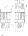
Fig. 1 zeigt zwei Draufsichten auf das Vorderteil gemäß einer ersten Ausführungsform der Erfindung, einmal mit durchgeschleifter Verdrahtung (rechte Abbildung) und zum anderen mit einem an einer Frontseite verschlossenen Durchbruch für die Leiter. Bei der V-Verdrahtung werden die Leiter durch gegenüberliegende Durchbrüche hindurchgeschoben; beim Stich-Anschluss (linke Darstellung) lediglich eingeschoben; -
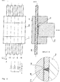
Fig. 2 zeigt eine Draufsicht und einen Längsschnitt der erfindungsgemäßen Überspannungsschutzeinrichtung mit Detaildarstellung A längs der Linie A-A, aus der das Prinzip der Vampir-Schneidtechnik bzw. Vampir-Klemmtechnik erkennbar ist; -
Fig. 3 nimmt Bezug auf die zweite Ausführungsform der Erfindung mit einem Sockelteil, das eine Rastplatte besitzt, das zum Steckteil weisende Kontaktflächen sowie zu den Leitern gerichtete Schneidflächen enthält. -
Fig. 4 zeigt ein prinzipielles Steckteil, geeignet für einen Einsatz bei Verwendung des Unterteils gemäßFig. 3 . -
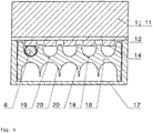
Fig. 5 stellt einen Querschnitt durch das erfindungsgemäße Steckteil mit einer Leiteradernplatte dar, die rinnenförmige Ausnehmungen unterschiedlichen Durchmessers besitzt, um einen Anschluss von Adernquerschnitten unterschiedlicher Abmessungen zu gewährleisten. - Mit Hilfe der
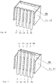
Fig. 6 und 7 ist als perspektivische Ansicht das Sockelteil mit aufgenommener Leiteradernplatte dargestellt, die bezüglich der Aufnahme von Leitern unterschiedlicher Querschnitte im Aufnahmehohlraum des Sockelteils gewendet eingesetzt werden kann. - Die
Fig. 8 zeigt in Fortbildung derFig. 6 und 7 die Rastplatte mit im Bild nach unten gerichteten Schneidflächen zur Kontaktierung der entsprechenden Leiter auf der Basis der Vampir-Schneid-Klemmtechnik. -
Fig. 9 schließt an die Darstellung nachFig. 8 an. Nach der mittels Pfeildarstellung nachFig. 8 ausgeführten Bewegung rastet die Platte mit den Schneidklemmen in einer entsprechenden Ausnehmung in der Seitenwandung des Sockelteils ein und stellt die sichere Kontaktierung der ansonsten nicht abisolierten Leiter her. -
Fig. 10 stellt die komplette Einheit aus Sockelteil mit Adernplatte und kontaktierten Leitern und Steckteil dar. - Gemäß den Prinzipdarstellungen nach den
Fig. 1 und2 wird gemäß der ersten Ausführungsform der Erfindung von einem Sockelteil 1 ausgegangen, das, wie die Querschnittsdarstellung gemäßFig. 2 , oben rechts, deutlich werden lässt, eine U-förmige Gestalt besitzt. - Im Sockelteil 1 ist ein Steckteil 2 rastend, aber austauschbar einbringbar.
- Das Steckteil 2 weist Mittel zum Überspannungsschutz auf. Diese Mittel können z.B. Funkenstrecken, Varistoren oder dergleichen umfassen.
- Im Sockelteil 1 werden elektrische Leiter L1, L2, L3, N, PE kontaktiert. Diesbezüglich sind stirnseitig Öffnungen oder Durchbrüche 3 vorhanden, die dem Einschieben oder Durchschieben der elektrischen Leiter L1, L2, L3, N und/oder PE dienen.
- Die Darstellungen nach
Fig. 1 lassen erkennen, dass die Leiter L1, L2, L3, N und PE in einem Bereich 4 des Sockelteils 1 freiliegen. Dieser Bereich 4 wird später vom Steckteil 2 überdeckt. - Am Boden des Steckteils 2 befindliche Schneidflächen 5 sind in der Lage, beim Einstecken des Steckteils 2 die Leiterisolation 6 zu durchdringen und den metallischen Kern 7 des betreffenden Leiters 8 zu kontaktieren.
- Bei einem Stich-Anschluss können die vorerwähnten Öffnungen oder Durchbrüche 3 an einer Seite des Steckteils 2 verschlossen werden oder verschlossen bleiben.
- Beim V-Anschluss sind beide Öffnungen an den gegenüberliegenden Seiten frei und insofern als Durchbruch gestaltet.
- Über eine entsprechende Kontaktierung und Ausführung der Schneidflächen 5 am jeweiligen Steckteil 2 in Verbindung mit einem Wählschalter können die entsprechenden Netzsysteme TT-/TNS bzw. TNC gewählt werden, was in den Darstellungen nach
Fig. 2 angedeutet ist. - Bei der zweiten Ausführung der Erfindung wird von einem universellen Sockelteil 11 ausgegangen, das wiederum über entsprechende Öffnungen 3 Leiter 8 aufnimmt.
- Das Sockelteil 11 nimmt bei dieser Ausführungsform eine Rastplatte 12 mit Vampir- oder Schneid-Klemmtechnik zum Einrasten in das Sockelteil auf.
- Diesbezüglich weist die Rastplatte 12 an ihrer Oberseite, d.h. an der zum in der
Fig. 3 nicht gezeigten Steckteil gerichteten Fläche Kontaktflächen 13 auf. - Zu den Leitern 8 hin gerichtet weist die Rastplatte 12 Schneidflächen 14 auf, die beim Eindrücken oder Einpressen der Rastplatte 12 die Leiterisolierung durchdringen und den Leiterkern kontaktieren.
- Diesbezüglich sind bei einer vormontierten Rastplatte 12 in einem der U-Schenkel des Sockelteils 11 Rastausnehmungen 15 vorhanden.
- Beim späteren Einsetzen des für die zweite Ausführungsform spezifizierten Steckteils 2 (siehe
Fig. 4 ) kontaktieren dort ausgebildete Kontaktgegenflächen 16 die Kontaktflächen 13. - Die
Fig. 5 ff. lassen darüber hinaus erkennen, dass im Sockelteil 1 bzw. 11 ein Aufnahmehohlraum 17 für eine Leiteradernplatte 18 vorgesehen ist. - Die Leiteradernplatte 18 weist eine der Leiteranzahl 8 entsprechende Ausbildung von rinnenartigen Ausnehmungen 19 auf.
- Die Leiteradernplatte 18 ist als Einsatzteil ausgebildet und kann aus dem Aufnahmehohlraum 17 entnommen und gewendet wieder eingesetzt werden. Dabei können mit Hilfe der unterschiedlichen Formen der rinnenartigen Ausnehmungen 19 bzw. 20 auf den verschiedenen Seiten Leiter mit unterschiedlichen Querschnitten, z.B. 10/16 mm2 oder 25/35 mm2, aufgenommen werden.
- Die möglichen Ausgestaltungen der Verdrahtung nach Stichanschluss bzw. V-Anschluss sind in den
Fig. 6 und 7 illustriert, wobei auch dort die Möglichkeit des Wendens der Adernplatte nachvollziehbar ist. - Der Vorgang des Vampir-Schneidklemm-Kontaktierens ist anhand der
Fig. 8 nachvollziehbar, welche symbolisch die Kontaktplatte 12 zeigt, die an ihrer zu den Leitern L1, L2, L3, N und PE gerichteten Seite die entsprechenden Vampir-Schneidklemmen 14 umfasst und Fenster aufweist, die die Kontaktflächen 13 rückseitig von den jeweiligen Schneidklemmen bilden. - Die Pfeildarstellung symbolisiert die Schwenk-, Rast- und damit verbundene Schneid-Klemm-Kontaktierungsbewegung.
- Die
Fig. 9 stellt den Zustand nach eingerasteter Platte 12 dar, wobei nunmehr die gewünschte elektrische Kontaktierung der Leiter vorliegt. - In an sich bekannter Weise kann dann gemäß der Darstellung nach
Fig. 10 das eigentliche Steckteil 2, ausgebildet als Schutzmodul, rastend mit dem Sockelteil 1; 11 verbunden werden.
Claims (7)
- Überspannungsschutzeinrichtung mit mindestens einem Überspannungsschutzgerät, bestehend aus einem im Wesentlichen U-förmigen Sockelteil (1) und einem, im Sockelteil (1) fixierbaren Steckteil (2), welches Mittel zum Überspannungsschutz aufnimmt, wobei am oder im Sockelteil (1) isolierte elektrische Leiter (8) mittels Vampir- oder Schneidklemmen kontaktiert werden, sowie im Sockelteil (1) Durchbrüche (3) zur Leiteraufnahme ausgebildet sind, wobei die Durchbrüche (3) zum Einschieben im Falle eines Stich-Anschlusses oder Durchschieben im Falle eines V-Anschlusses der elektrischen Leiter (8) ausgeführt sind und in einem Bereich (4) des Sockelteils (1), welcher vom Steckteil (2) überdeckbar ist, freiliegen, derart, dass am Boden des Steckteils (2) befindliche Schneidflächen (5) die Leiterisolation (6) beim Steckvorgang durchdringen und den jeweiligen Leiter (8) unmittelbar kontaktieren, wobei bei einem Stich-Anschluss die Durchbrüche (3) an einer Seite des Steckteils (2) verschlossen werden und bei einem V-Anschluss die Durchbrüche an den gegenüberliegenden Seiten frei gestaltet sind, dadurch gekennzeichnet, dass im Sockelteil (1) ein Aufnahmehohlraum (17) für eine Leiteradernplatte (18) vorgesehen ist, wobei die Leiteradernplatte (18) eine der Leiteranzahl entsprechende Ausbildung von rinnenartigen Ausnehmungen (19) aufweist.
- Überspannungsschutzeinrichtung mit mindestens einem Überspannungsschutzgerät, bestehend aus einem im Wesentlichen U-förmigen Sockelteil (1) und einem, im Sockelteil (1) fixierbaren Steckteil (2), welches Mittel zum Überspannungsschutz aufnimmt, wobei am oder im Sockelteil (1) isolierte elektrische Leiter (8) mittels Vampir- oder Schneidklemmen kontaktiert werden, sowie im Sockelteil (1) Durchbrüche (3) zur Leiteraufnahme ausgebildet sind, wobei die Durchbrüche (3) zum Einschieben im Falle eines Stich-Anschlusses oder Durchschieben im Falle eines V-Anschlusses der elektrischen Leiter (8) ausgeführt sind und in einem Bereich (4) des Sockelteils (1), welcher vom Steckteil (2) überdeckbar ist, freiliegen, wobei bei einem Stich-Anschluss die Durchbrüche (3) an einer Seite des Steckteils (2) verschlossen werden und bei einem V-Anschluss die Durchbrüche an den gegenüberliegenden Seiten frei gestaltet sind,
dadurch gekennzeichnet dass
das Sockelteil (1) eine Rastplatte (12) oder mehrere Raststege besitzt oder aufnimmt, welche zum Steckteil (2) weisende Kontaktflächen (13) sowie zu den Leitern (8) gerichtete Schneidflächen (14) aufweisen, derart, dass beim Einpressen oder Einrasten die Schneidflächen (14) die Leiterisolation (6) durchdringen und die jeweiligen Leiter (8) kontaktieren, so dass zwischen den jeweiligen Kontaktflächen (13) und dem jeweiligen Leiter (8) eine elektrische Verbindung hergestellt ist, und dass
im Sockelteil (1) ein Aufnahmehohlraum (17) für eine Leiteradernplatte (18) vorgesehen ist, wobei die Leiteradernplatte (18) eine der Leiteranzahl entsprechende Ausbildung von rinnenartigen Ausnehmungen (19) aufweist. - Überspannungsschutzeinrichtung nach Anspruch 2,
dadurch gekennzeichnet, dass
das Steckteil (2) an seinem Boden leitfähige Abschnitte (16) besitzt, welche in Lage und Richtung mit den Kontaktflächen (13) der Rastplatte (12) oder den Raststegen korrespondieren. - Überspannungsschutzeinrichtung nach Anspruch 1 oder 2,
dadurch gekennzeichnet, dass
die Leiteradernplatte (18) die jeweiligen elektrischen Leiter (8) beim Schneid-Klemm-Kontaktierungsvorgang abstützt. - Überspannungsschutzeinrichtung nach Anspruch 1, 2 oder 4,
dadurch gekennzeichnet, dass
die Leiteradernplatte (18) als Einsatzteil ausgebildet ist und die rinnenartigen Ausnehmungen (19) eine an den Leiterquerschnitt angepasste Form besitzen. - Überspannungsschutzeinrichtung nach Anspruch 5,
dadurch gekennzeichnet, dass
die Leiteradernplatte (18) aus dem Aufnahmehohlraum (17) entnommen und gewendet einsetzbar ist, wobei eine erste Oberflächenseite der Leiteradernplatte (18) Rinnen (19) für Leiter mit einem ersten Querschnitt und eine zweite Oberflächenseite Rinnen (20) für Leiter mit einem zweiten Querschnitt besitzt. - Überspannungsschutzeinrichtung nach Anspruch 6,
dadurch gekennzeichnet, dass
sich die Rinnenform (19; 20) und die Querschnitte der Leiter unterscheiden.
Priority Applications (1)
| Application Number | Priority Date | Filing Date | Title |
|---|---|---|---|
| SI201531500T SI3117487T1 (sl) | 2014-03-13 | 2015-02-10 | Priprava za prenapetostno zaščito z vsaj eno napravo za prenapetostno zaščito |
Applications Claiming Priority (3)
| Application Number | Priority Date | Filing Date | Title |
|---|---|---|---|
| DE102014003693 | 2014-03-13 | ||
| DE102014007352.1A DE102014007352A1 (de) | 2014-03-13 | 2014-05-19 | Überspannungsschutzeinrichtung mit mindestens einem Überspannungsschutzgerät |
| PCT/EP2015/052717 WO2015135709A1 (de) | 2014-03-13 | 2015-02-10 | Überspannungsschutzeinrichtung mit mindestens einem überspannungsschutzgerät |
Publications (2)
| Publication Number | Publication Date |
|---|---|
| EP3117487A1 EP3117487A1 (de) | 2017-01-18 |
| EP3117487B1 true EP3117487B1 (de) | 2020-11-04 |
Family
ID=54009975
Family Applications (1)
| Application Number | Title | Priority Date | Filing Date |
|---|---|---|---|
| EP15704291.2A Active EP3117487B1 (de) | 2014-03-13 | 2015-02-10 | Überspannungsschutzeinrichtung mit mindestens einem überspannungsschutzgerät |
Country Status (8)
| Country | Link |
|---|---|
| US (1) | US9780463B2 (de) |
| EP (1) | EP3117487B1 (de) |
| JP (1) | JP6426196B2 (de) |
| CN (1) | CN106134003B (de) |
| DE (1) | DE102014007352A1 (de) |
| ES (1) | ES2847405T3 (de) |
| SI (1) | SI3117487T1 (de) |
| WO (1) | WO2015135709A1 (de) |
Families Citing this family (3)
| Publication number | Priority date | Publication date | Assignee | Title |
|---|---|---|---|---|
| DE102018107604A1 (de) | 2018-02-27 | 2019-08-29 | Dehn + Söhne Gmbh + Co. Kg | Überspannungsschutzeinrichtung mit mindestens einem Überspannungsschutzgerät, bestehend aus einem Sockelteil und einem mit dem Sockelteil verbindbaren Steckteil |
| CN110335792A (zh) * | 2019-07-30 | 2019-10-15 | 青岛海尔家居集成股份有限公司 | 一种刺破式剩余电流动作保护器及其使用方法 |
| DE102022103262A1 (de) * | 2022-02-11 | 2023-08-17 | Wieland Electric Gmbh | Positionierungselement für eine Anzahl von parallel verlaufenden Einzelleitern |
Family Cites Families (23)
| Publication number | Priority date | Publication date | Assignee | Title |
|---|---|---|---|---|
| JPS5821081Y2 (ja) * | 1977-09-22 | 1983-05-04 | ヒロセ電機株式会社 | 電気コネクタ |
| US4422709A (en) * | 1981-09-28 | 1983-12-27 | Amp Incorporated | Multiple transducer connector |
| KR890005362B1 (ko) * | 1984-03-19 | 1989-12-23 | 더 뱁콕 앤드 윌콕스 컴퍼니 | 전기 커넥터 블럭 |
| DE3917270C2 (de) | 1989-05-23 | 1997-10-23 | Krone Ag | Anschlußleiste mit Überspannungsschutz |
| US5153988A (en) * | 1990-03-26 | 1992-10-13 | Raychem Corporation | Method of making modular telecommunications terminal block |
| FR2671671A1 (fr) | 1991-01-10 | 1992-07-17 | Mars Actel | Reglette de raccordement a protections semi-integrees. |
| GB9103872D0 (en) * | 1991-02-25 | 1991-04-10 | Raychem Sa Nv | Electrical connector block |
| GB9124180D0 (en) * | 1991-11-14 | 1992-01-08 | Raychem Sa Nv | Electrical connector |
| FR2708794B1 (fr) | 1993-08-04 | 1995-09-15 | Pouyet Int | Module d'interconnexion rapide de deux lignes téléphoniques monopaires. |
| DE9402468U1 (de) | 1994-02-15 | 1995-03-16 | Krone GmbH, 14167 Berlin | Modulares Anschlußsystem |
| US5802170A (en) | 1994-05-19 | 1998-09-01 | Tii Industries, Inc. | Customer bridge module |
| JP2003217749A (ja) * | 2002-01-21 | 2003-07-31 | Sumitomo Wiring Syst Ltd | エアバッグ用コネクタ |
| DE102004054203A1 (de) * | 2004-11-10 | 2006-05-11 | Erni Elektroapparate Gmbh | Schneidklemm-Steckkontaktleiste für elektrische Steckverbinder |
| DE102005005914A1 (de) * | 2005-02-09 | 2006-08-10 | Dehn + Söhne Gmbh + Co. Kg | Steckbare Gerätekombination zum Schutz vor Überspannungen |
| JP4694976B2 (ja) * | 2006-02-03 | 2011-06-08 | 三菱電線工業株式会社 | 電線の圧接ジョイントコネクタ |
| US7442070B2 (en) * | 2007-02-15 | 2008-10-28 | Super Link Electronics Co., Ltd. | Light-emitting cell module |
| NL2003323C2 (nl) | 2009-07-31 | 2011-02-02 | Abb Bv | Kabelsysteem. |
| DE102010012684A1 (de) * | 2010-03-24 | 2011-09-29 | Phoenix Contact Gmbh & Co. Kg | Überspannungsschutzgerät |
| WO2012047383A2 (en) * | 2010-09-30 | 2012-04-12 | Phoenix Contact Development & Manufacturing, Inc. | Terminal block for surge protection having integral disconnect |
| JP5387863B2 (ja) * | 2011-03-31 | 2014-01-15 | 日本電気株式会社 | プレスフィットコネクタ |
| CZ304868B6 (cs) * | 2011-04-01 | 2014-12-17 | Saltek S.R.O. | Svodič přepětí s výměnným modulem přepěťové ochrany |
| DE102012103789A1 (de) | 2012-04-30 | 2013-10-31 | Sma Solar Technology Ag | Kabelclip für Modulelektronik |
| DE102012025107A1 (de) * | 2012-12-21 | 2014-06-26 | Erni Production Gmbh & Co. Kg | Steckverbinderanordnung |
-
2014
- 2014-05-19 DE DE102014007352.1A patent/DE102014007352A1/de not_active Ceased
-
2015
- 2015-02-10 EP EP15704291.2A patent/EP3117487B1/de active Active
- 2015-02-10 CN CN201580013628.8A patent/CN106134003B/zh active Active
- 2015-02-10 SI SI201531500T patent/SI3117487T1/sl unknown
- 2015-02-10 JP JP2016557068A patent/JP6426196B2/ja active Active
- 2015-02-10 ES ES15704291T patent/ES2847405T3/es active Active
- 2015-02-10 US US15/125,695 patent/US9780463B2/en not_active Expired - Fee Related
- 2015-02-10 WO PCT/EP2015/052717 patent/WO2015135709A1/de not_active Ceased
Non-Patent Citations (1)
| Title |
|---|
| None * |
Also Published As
| Publication number | Publication date |
|---|---|
| EP3117487A1 (de) | 2017-01-18 |
| US9780463B2 (en) | 2017-10-03 |
| SI3117487T1 (sl) | 2021-03-31 |
| CN106134003A (zh) | 2016-11-16 |
| ES2847405T3 (es) | 2021-08-03 |
| JP2017508256A (ja) | 2017-03-23 |
| CN106134003B (zh) | 2019-01-29 |
| JP6426196B2 (ja) | 2018-11-21 |
| US20170005418A1 (en) | 2017-01-05 |
| DE102014007352A1 (de) | 2015-09-17 |
| WO2015135709A1 (de) | 2015-09-17 |
Similar Documents
| Publication | Publication Date | Title |
|---|---|---|
| EP0399628B1 (de) | Anschlussleiste mit Überspannungsschutz | |
| EP0645841B1 (de) | Reihenklemme | |
| EP3025396B1 (de) | Terminal zur kontaktierung eines elektrischen leiters | |
| EP1811604B1 (de) | Elektrischer Reihenklemmenblock | |
| EP2351154B1 (de) | Reihenklemmenanordnung mit querverbindern und prüfsteckern | |
| DE19906725C1 (de) | Leiteranschlußelement | |
| EP3631922B1 (de) | Stromverteiler | |
| EP2466697A1 (de) | Datenkabelanschlussmodul sowie ein Verfahren zu dessen Konfektion an einem Kabel | |
| EP3164913B1 (de) | Steckadapter für ein elektrisches gerät zum stecken von zuleitungen und system aus steckadapter und gerät | |
| EP3698438B1 (de) | Vorrichtung zur elektrischen kontaktierung | |
| DE102015110308B4 (de) | Akkupack für ein Elektrohandwerkzeuggerät | |
| EP3021421A1 (de) | Anschlussvorrichtung für mehrleiterkabel | |
| DE102010034790B4 (de) | Kontaktträger für wenigstens eine Vorrichtung zur Kontaktierung eines elektrischen Leiters mit einer Leiterbahn | |
| EP2600470B1 (de) | Anschlussvorrichtung für ein Flachbandkabel und elektrisches Gerät mit angeschlossenem Flachbandkabel | |
| EP3117487A1 (de) | Überspannungsschutzeinrichtung mit mindestens einem überspannungsschutzgerät | |
| DE102008025433B4 (de) | Klemmenanschlußblock | |
| DE2815660A1 (de) | Elektrischer verbinder | |
| DE29821211U1 (de) | Steckverbinderkontakt mit Schneidanschluß | |
| EP0921611B1 (de) | Netzstromanschlussdose und -schalter | |
| EP3759766B1 (de) | Überspannungsschutzeinrichtung mit mindestens einem überspannungsschutzgerät, bestehend aus einem sockelteil und einem mit dem sockelteil verbindbaren steckteil | |
| EP0905822A1 (de) | Kabelstecker mit Massekontaktierung | |
| EP4007075A1 (de) | Klemme für elektrische leiter zur potentialverteilung | |
| DE19937313C1 (de) | Messerkontakt | |
| EP3443618B1 (de) | Steckverbinder mit leitgummi | |
| EP0406533A1 (de) | Klemmverbinder |
Legal Events
| Date | Code | Title | Description |
|---|---|---|---|
| PUAI | Public reference made under article 153(3) epc to a published international application that has entered the european phase |
Free format text: ORIGINAL CODE: 0009012 |
|
| STAA | Information on the status of an ep patent application or granted ep patent |
Free format text: STATUS: REQUEST FOR EXAMINATION WAS MADE |
|
| 17P | Request for examination filed |
Effective date: 20160929 |
|
| AK | Designated contracting states |
Kind code of ref document: A1 Designated state(s): AL AT BE BG CH CY CZ DE DK EE ES FI FR GB GR HR HU IE IS IT LI LT LU LV MC MK MT NL NO PL PT RO RS SE SI SK SM TR |
|
| AX | Request for extension of the european patent |
Extension state: BA ME |
|
| DAX | Request for extension of the european patent (deleted) | ||
| STAA | Information on the status of an ep patent application or granted ep patent |
Free format text: STATUS: EXAMINATION IS IN PROGRESS |
|
| 17Q | First examination report despatched |
Effective date: 20180903 |
|
| RAP1 | Party data changed (applicant data changed or rights of an application transferred) |
Owner name: DEHN SE + CO KG |
|
| REG | Reference to a national code |
Ref country code: DE Ref legal event code: R079 Ref document number: 502015013745 Country of ref document: DE Free format text: PREVIOUS MAIN CLASS: H01R0004240000 Ipc: H01R0004242900 |
|
| GRAP | Despatch of communication of intention to grant a patent |
Free format text: ORIGINAL CODE: EPIDOSNIGR1 |
|
| STAA | Information on the status of an ep patent application or granted ep patent |
Free format text: STATUS: GRANT OF PATENT IS INTENDED |
|
| RIC1 | Information provided on ipc code assigned before grant |
Ipc: H01R 9/24 20060101ALI20200608BHEP Ipc: H01R 4/2429 20180101AFI20200608BHEP Ipc: H01R 9/26 20060101ALI20200608BHEP Ipc: H04M 1/74 20060101ALN20200608BHEP |
|
| INTG | Intention to grant announced |
Effective date: 20200626 |
|
| GRAS | Grant fee paid |
Free format text: ORIGINAL CODE: EPIDOSNIGR3 |
|
| GRAA | (expected) grant |
Free format text: ORIGINAL CODE: 0009210 |
|
| STAA | Information on the status of an ep patent application or granted ep patent |
Free format text: STATUS: THE PATENT HAS BEEN GRANTED |
|
| AK | Designated contracting states |
Kind code of ref document: B1 Designated state(s): AL AT BE BG CH CY CZ DE DK EE ES FI FR GB GR HR HU IE IS IT LI LT LU LV MC MK MT NL NO PL PT RO RS SE SI SK SM TR |
|
| REG | Reference to a national code |
Ref country code: GB Ref legal event code: FG4D Free format text: NOT ENGLISH |
|
| REG | Reference to a national code |
Ref country code: CH Ref legal event code: EP |
|
| REG | Reference to a national code |
Ref country code: AT Ref legal event code: REF Ref document number: 1332033 Country of ref document: AT Kind code of ref document: T Effective date: 20201115 |
|
| REG | Reference to a national code |
Ref country code: DE Ref legal event code: R096 Ref document number: 502015013745 Country of ref document: DE |
|
| REG | Reference to a national code |
Ref country code: IE Ref legal event code: FG4D Free format text: LANGUAGE OF EP DOCUMENT: GERMAN |
|
| REG | Reference to a national code |
Ref country code: NL Ref legal event code: MP Effective date: 20201104 |
|
| PG25 | Lapsed in a contracting state [announced via postgrant information from national office to epo] |
Ref country code: GR Free format text: LAPSE BECAUSE OF FAILURE TO SUBMIT A TRANSLATION OF THE DESCRIPTION OR TO PAY THE FEE WITHIN THE PRESCRIBED TIME-LIMIT Effective date: 20210205 Ref country code: FI Free format text: LAPSE BECAUSE OF FAILURE TO SUBMIT A TRANSLATION OF THE DESCRIPTION OR TO PAY THE FEE WITHIN THE PRESCRIBED TIME-LIMIT Effective date: 20201104 Ref country code: RS Free format text: LAPSE BECAUSE OF FAILURE TO SUBMIT A TRANSLATION OF THE DESCRIPTION OR TO PAY THE FEE WITHIN THE PRESCRIBED TIME-LIMIT Effective date: 20201104 Ref country code: NO Free format text: LAPSE BECAUSE OF FAILURE TO SUBMIT A TRANSLATION OF THE DESCRIPTION OR TO PAY THE FEE WITHIN THE PRESCRIBED TIME-LIMIT Effective date: 20210204 Ref country code: PT Free format text: LAPSE BECAUSE OF FAILURE TO SUBMIT A TRANSLATION OF THE DESCRIPTION OR TO PAY THE FEE WITHIN THE PRESCRIBED TIME-LIMIT Effective date: 20210304 |
|
| PGFP | Annual fee paid to national office [announced via postgrant information from national office to epo] |
Ref country code: CZ Payment date: 20210127 Year of fee payment: 7 |
|
| PG25 | Lapsed in a contracting state [announced via postgrant information from national office to epo] |
Ref country code: SE Free format text: LAPSE BECAUSE OF FAILURE TO SUBMIT A TRANSLATION OF THE DESCRIPTION OR TO PAY THE FEE WITHIN THE PRESCRIBED TIME-LIMIT Effective date: 20201104 Ref country code: IS Free format text: LAPSE BECAUSE OF FAILURE TO SUBMIT A TRANSLATION OF THE DESCRIPTION OR TO PAY THE FEE WITHIN THE PRESCRIBED TIME-LIMIT Effective date: 20210304 Ref country code: PL Free format text: LAPSE BECAUSE OF FAILURE TO SUBMIT A TRANSLATION OF THE DESCRIPTION OR TO PAY THE FEE WITHIN THE PRESCRIBED TIME-LIMIT Effective date: 20201104 Ref country code: LV Free format text: LAPSE BECAUSE OF FAILURE TO SUBMIT A TRANSLATION OF THE DESCRIPTION OR TO PAY THE FEE WITHIN THE PRESCRIBED TIME-LIMIT Effective date: 20201104 Ref country code: BG Free format text: LAPSE BECAUSE OF FAILURE TO SUBMIT A TRANSLATION OF THE DESCRIPTION OR TO PAY THE FEE WITHIN THE PRESCRIBED TIME-LIMIT Effective date: 20210204 |
|
| PGFP | Annual fee paid to national office [announced via postgrant information from national office to epo] |
Ref country code: SI Payment date: 20210128 Year of fee payment: 7 Ref country code: ES Payment date: 20210323 Year of fee payment: 7 |
|
| REG | Reference to a national code |
Ref country code: LT Ref legal event code: MG9D |
|
| PG25 | Lapsed in a contracting state [announced via postgrant information from national office to epo] |
Ref country code: HR Free format text: LAPSE BECAUSE OF FAILURE TO SUBMIT A TRANSLATION OF THE DESCRIPTION OR TO PAY THE FEE WITHIN THE PRESCRIBED TIME-LIMIT Effective date: 20201104 |
|
| PG25 | Lapsed in a contracting state [announced via postgrant information from national office to epo] |
Ref country code: LT Free format text: LAPSE BECAUSE OF FAILURE TO SUBMIT A TRANSLATION OF THE DESCRIPTION OR TO PAY THE FEE WITHIN THE PRESCRIBED TIME-LIMIT Effective date: 20201104 Ref country code: SK Free format text: LAPSE BECAUSE OF FAILURE TO SUBMIT A TRANSLATION OF THE DESCRIPTION OR TO PAY THE FEE WITHIN THE PRESCRIBED TIME-LIMIT Effective date: 20201104 Ref country code: RO Free format text: LAPSE BECAUSE OF FAILURE TO SUBMIT A TRANSLATION OF THE DESCRIPTION OR TO PAY THE FEE WITHIN THE PRESCRIBED TIME-LIMIT Effective date: 20201104 Ref country code: SM Free format text: LAPSE BECAUSE OF FAILURE TO SUBMIT A TRANSLATION OF THE DESCRIPTION OR TO PAY THE FEE WITHIN THE PRESCRIBED TIME-LIMIT Effective date: 20201104 Ref country code: EE Free format text: LAPSE BECAUSE OF FAILURE TO SUBMIT A TRANSLATION OF THE DESCRIPTION OR TO PAY THE FEE WITHIN THE PRESCRIBED TIME-LIMIT Effective date: 20201104 |
|
| REG | Reference to a national code |
Ref country code: ES Ref legal event code: FG2A Ref document number: 2847405 Country of ref document: ES Kind code of ref document: T3 Effective date: 20210803 |
|
| REG | Reference to a national code |
Ref country code: DE Ref legal event code: R097 Ref document number: 502015013745 Country of ref document: DE |
|
| PG25 | Lapsed in a contracting state [announced via postgrant information from national office to epo] |
Ref country code: DK Free format text: LAPSE BECAUSE OF FAILURE TO SUBMIT A TRANSLATION OF THE DESCRIPTION OR TO PAY THE FEE WITHIN THE PRESCRIBED TIME-LIMIT Effective date: 20201104 |
|
| PLBE | No opposition filed within time limit |
Free format text: ORIGINAL CODE: 0009261 |
|
| STAA | Information on the status of an ep patent application or granted ep patent |
Free format text: STATUS: NO OPPOSITION FILED WITHIN TIME LIMIT |
|
| PG25 | Lapsed in a contracting state [announced via postgrant information from national office to epo] |
Ref country code: MC Free format text: LAPSE BECAUSE OF FAILURE TO SUBMIT A TRANSLATION OF THE DESCRIPTION OR TO PAY THE FEE WITHIN THE PRESCRIBED TIME-LIMIT Effective date: 20201104 |
|
| 26N | No opposition filed |
Effective date: 20210805 |
|
| GBPC | Gb: european patent ceased through non-payment of renewal fee |
Effective date: 20210210 |
|
| REG | Reference to a national code |
Ref country code: BE Ref legal event code: MM Effective date: 20210228 |
|
| PG25 | Lapsed in a contracting state [announced via postgrant information from national office to epo] |
Ref country code: IT Free format text: LAPSE BECAUSE OF FAILURE TO SUBMIT A TRANSLATION OF THE DESCRIPTION OR TO PAY THE FEE WITHIN THE PRESCRIBED TIME-LIMIT Effective date: 20201104 Ref country code: CH Free format text: LAPSE BECAUSE OF NON-PAYMENT OF DUE FEES Effective date: 20210228 Ref country code: AL Free format text: LAPSE BECAUSE OF FAILURE TO SUBMIT A TRANSLATION OF THE DESCRIPTION OR TO PAY THE FEE WITHIN THE PRESCRIBED TIME-LIMIT Effective date: 20201104 Ref country code: LI Free format text: LAPSE BECAUSE OF NON-PAYMENT OF DUE FEES Effective date: 20210228 Ref country code: LU Free format text: LAPSE BECAUSE OF NON-PAYMENT OF DUE FEES Effective date: 20210210 Ref country code: NL Free format text: LAPSE BECAUSE OF FAILURE TO SUBMIT A TRANSLATION OF THE DESCRIPTION OR TO PAY THE FEE WITHIN THE PRESCRIBED TIME-LIMIT Effective date: 20201104 |
|
| PG25 | Lapsed in a contracting state [announced via postgrant information from national office to epo] |
Ref country code: IE Free format text: LAPSE BECAUSE OF NON-PAYMENT OF DUE FEES Effective date: 20210210 Ref country code: GB Free format text: LAPSE BECAUSE OF NON-PAYMENT OF DUE FEES Effective date: 20210210 |
|
| REG | Reference to a national code |
Ref country code: AT Ref legal event code: MM01 Ref document number: 1332033 Country of ref document: AT Kind code of ref document: T Effective date: 20210210 |
|
| PG25 | Lapsed in a contracting state [announced via postgrant information from national office to epo] |
Ref country code: AT Free format text: LAPSE BECAUSE OF NON-PAYMENT OF DUE FEES Effective date: 20210210 |
|
| PG25 | Lapsed in a contracting state [announced via postgrant information from national office to epo] |
Ref country code: BE Free format text: LAPSE BECAUSE OF NON-PAYMENT OF DUE FEES Effective date: 20210228 |
|
| REG | Reference to a national code |
Ref country code: DE Ref legal event code: R081 Ref document number: 502015013745 Country of ref document: DE Owner name: DEHN SE, DE Free format text: FORMER OWNER: DEHN SE + CO KG, 92318 NEUMARKT, DE |
|
| PG25 | Lapsed in a contracting state [announced via postgrant information from national office to epo] |
Ref country code: CZ Free format text: LAPSE BECAUSE OF NON-PAYMENT OF DUE FEES Effective date: 20220210 |
|
| PG25 | Lapsed in a contracting state [announced via postgrant information from national office to epo] |
Ref country code: SI Free format text: LAPSE BECAUSE OF NON-PAYMENT OF DUE FEES Effective date: 20220211 |
|
| REG | Reference to a national code |
Ref country code: SI Ref legal event code: KO00 Effective date: 20221013 |
|
| REG | Reference to a national code |
Ref country code: ES Ref legal event code: FD2A Effective date: 20230403 |
|
| PG25 | Lapsed in a contracting state [announced via postgrant information from national office to epo] |
Ref country code: ES Free format text: LAPSE BECAUSE OF NON-PAYMENT OF DUE FEES Effective date: 20220211 |
|
| PG25 | Lapsed in a contracting state [announced via postgrant information from national office to epo] |
Ref country code: HU Free format text: LAPSE BECAUSE OF FAILURE TO SUBMIT A TRANSLATION OF THE DESCRIPTION OR TO PAY THE FEE WITHIN THE PRESCRIBED TIME-LIMIT; INVALID AB INITIO Effective date: 20150210 |
|
| PG25 | Lapsed in a contracting state [announced via postgrant information from national office to epo] |
Ref country code: CY Free format text: LAPSE BECAUSE OF FAILURE TO SUBMIT A TRANSLATION OF THE DESCRIPTION OR TO PAY THE FEE WITHIN THE PRESCRIBED TIME-LIMIT Effective date: 20201104 |
|
| PG25 | Lapsed in a contracting state [announced via postgrant information from national office to epo] |
Ref country code: MK Free format text: LAPSE BECAUSE OF FAILURE TO SUBMIT A TRANSLATION OF THE DESCRIPTION OR TO PAY THE FEE WITHIN THE PRESCRIBED TIME-LIMIT Effective date: 20201104 |
|
| PGFP | Annual fee paid to national office [announced via postgrant information from national office to epo] |
Ref country code: FR Payment date: 20240216 Year of fee payment: 10 |
|
| PG25 | Lapsed in a contracting state [announced via postgrant information from national office to epo] |
Ref country code: MT Free format text: LAPSE BECAUSE OF FAILURE TO SUBMIT A TRANSLATION OF THE DESCRIPTION OR TO PAY THE FEE WITHIN THE PRESCRIBED TIME-LIMIT Effective date: 20201104 |
|
| PG25 | Lapsed in a contracting state [announced via postgrant information from national office to epo] |
Ref country code: TR Free format text: LAPSE BECAUSE OF FAILURE TO SUBMIT A TRANSLATION OF THE DESCRIPTION OR TO PAY THE FEE WITHIN THE PRESCRIBED TIME-LIMIT Effective date: 20201104 |
|
| PG25 | Lapsed in a contracting state [announced via postgrant information from national office to epo] |
Ref country code: FR Free format text: LAPSE BECAUSE OF NON-PAYMENT OF DUE FEES Effective date: 20250228 |
|
| PGFP | Annual fee paid to national office [announced via postgrant information from national office to epo] |
Ref country code: DE Payment date: 20260217 Year of fee payment: 12 |