EP3116695B1 - Vorrichtung zum lochen eines heft- und/oder lochrandes eines druckmediums - Google Patents
Vorrichtung zum lochen eines heft- und/oder lochrandes eines druckmediums Download PDFInfo
- Publication number
- EP3116695B1 EP3116695B1 EP15708735.4A EP15708735A EP3116695B1 EP 3116695 B1 EP3116695 B1 EP 3116695B1 EP 15708735 A EP15708735 A EP 15708735A EP 3116695 B1 EP3116695 B1 EP 3116695B1
- Authority
- EP
- European Patent Office
- Prior art keywords
- hole
- punch
- punching
- printed medium
- holes
- Prior art date
- Legal status (The legal status is an assumption and is not a legal conclusion. Google has not performed a legal analysis and makes no representation as to the accuracy of the status listed.)
- Active
Links
Images
Classifications
-
- B—PERFORMING OPERATIONS; TRANSPORTING
- B26—HAND CUTTING TOOLS; CUTTING; SEVERING
- B26D—CUTTING; DETAILS COMMON TO MACHINES FOR PERFORATING, PUNCHING, CUTTING-OUT, STAMPING-OUT OR SEVERING
- B26D5/00—Arrangements for operating and controlling machines or devices for cutting, cutting-out, stamping-out, punching, perforating, or severing by means other than cutting
- B26D5/20—Arrangements for operating and controlling machines or devices for cutting, cutting-out, stamping-out, punching, perforating, or severing by means other than cutting with interrelated action between the cutting member and work feed
- B26D5/30—Arrangements for operating and controlling machines or devices for cutting, cutting-out, stamping-out, punching, perforating, or severing by means other than cutting with interrelated action between the cutting member and work feed having the cutting member controlled by scanning a record carrier
- B26D5/34—Arrangements for operating and controlling machines or devices for cutting, cutting-out, stamping-out, punching, perforating, or severing by means other than cutting with interrelated action between the cutting member and work feed having the cutting member controlled by scanning a record carrier scanning being effected by a photosensitive device
-
- B—PERFORMING OPERATIONS; TRANSPORTING
- B26—HAND CUTTING TOOLS; CUTTING; SEVERING
- B26D—CUTTING; DETAILS COMMON TO MACHINES FOR PERFORATING, PUNCHING, CUTTING-OUT, STAMPING-OUT OR SEVERING
- B26D5/00—Arrangements for operating and controlling machines or devices for cutting, cutting-out, stamping-out, punching, perforating, or severing by means other than cutting
- B26D5/20—Arrangements for operating and controlling machines or devices for cutting, cutting-out, stamping-out, punching, perforating, or severing by means other than cutting with interrelated action between the cutting member and work feed
- B26D5/30—Arrangements for operating and controlling machines or devices for cutting, cutting-out, stamping-out, punching, perforating, or severing by means other than cutting with interrelated action between the cutting member and work feed having the cutting member controlled by scanning a record carrier
- B26D5/32—Arrangements for operating and controlling machines or devices for cutting, cutting-out, stamping-out, punching, perforating, or severing by means other than cutting with interrelated action between the cutting member and work feed having the cutting member controlled by scanning a record carrier with the record carrier formed by the work itself
-
- B—PERFORMING OPERATIONS; TRANSPORTING
- B26—HAND CUTTING TOOLS; CUTTING; SEVERING
- B26D—CUTTING; DETAILS COMMON TO MACHINES FOR PERFORATING, PUNCHING, CUTTING-OUT, STAMPING-OUT OR SEVERING
- B26D7/00—Details of apparatus for cutting, cutting-out, stamping-out, punching, perforating, or severing by means other than cutting
- B26D7/01—Means for holding or positioning work
- B26D7/015—Means for holding or positioning work for sheet material or piles of sheets
-
- B—PERFORMING OPERATIONS; TRANSPORTING
- B26—HAND CUTTING TOOLS; CUTTING; SEVERING
- B26D—CUTTING; DETAILS COMMON TO MACHINES FOR PERFORATING, PUNCHING, CUTTING-OUT, STAMPING-OUT OR SEVERING
- B26D7/00—Details of apparatus for cutting, cutting-out, stamping-out, punching, perforating, or severing by means other than cutting
- B26D7/06—Arrangements for feeding or delivering work of other than sheet, web, or filamentary form
- B26D7/0625—Arrangements for feeding or delivering work of other than sheet, web, or filamentary form by endless conveyors, e.g. belts
-
- B—PERFORMING OPERATIONS; TRANSPORTING
- B26—HAND CUTTING TOOLS; CUTTING; SEVERING
- B26F—PERFORATING; PUNCHING; CUTTING-OUT; STAMPING-OUT; SEVERING BY MEANS OTHER THAN CUTTING
- B26F1/00—Perforating; Punching; Cutting-out; Stamping-out; Apparatus therefor
- B26F1/02—Perforating by punching, e.g. with relatively-reciprocating punch and bed
-
- B—PERFORMING OPERATIONS; TRANSPORTING
- B26—HAND CUTTING TOOLS; CUTTING; SEVERING
- B26D—CUTTING; DETAILS COMMON TO MACHINES FOR PERFORATING, PUNCHING, CUTTING-OUT, STAMPING-OUT OR SEVERING
- B26D5/00—Arrangements for operating and controlling machines or devices for cutting, cutting-out, stamping-out, punching, perforating, or severing by means other than cutting
- B26D5/08—Means for actuating the cutting member to effect the cut
- B26D5/14—Crank and pin means
-
- B—PERFORMING OPERATIONS; TRANSPORTING
- B26—HAND CUTTING TOOLS; CUTTING; SEVERING
- B26F—PERFORATING; PUNCHING; CUTTING-OUT; STAMPING-OUT; SEVERING BY MEANS OTHER THAN CUTTING
- B26F1/00—Perforating; Punching; Cutting-out; Stamping-out; Apparatus therefor
- B26F1/0092—Perforating means specially adapted for printing machines
Definitions
- the invention relates to a device for punching a stitching and / or hole edge of a printing medium having at least two holes, the device being associated with a printing medium output of a printing medium processing device.
- Previously known devices for punching are made as 2-fold, 4-fold or 3-hole punch. That these punches have 2 or 4 or 3 punches. Depending on the distances between the individual punches, these punches can only produce the corresponding hole pattern given to them in each case. If you want to change over from a 2-fold or 4-hole punching to a 3-fold punching, the 2-fold or 4-hole punch must be exchanged for a 3-hole punch.
- the known punches are in two planes to the printing medium such. a document, folder, stack of paper or the like moves and positioned. This positioning means a complicated and above all expensive construction with appropriate measuring and positioning control.
- JP H06 126699 A a device for punching a stitching and / or perforated edge of a printing medium has already become known, in which a stationary printing medium is used, on which a punching module having only one lifting or punching punch can be moved along, the hole punching module can be positioned to the fixed pressure medium, that the perforation of at least one Abheftloches can be introduced at predeterminable hole position in the stitching and / or hole edge of the print medium.
- the disadvantage is, in addition to an additional, complicated traversing device for the hole punch module, a susceptible, flexible supply for the drive medium for the actuator of the punch module.
- a punching device described above which works with a 2, 3 or 4-hole punch
- the printing medium to the device for punching the stitching and / or hole edge is positionable such that the distance of the hole from the edge of the print medium adjustable is.
- the distance between the holes is fixed.
- the position of the holes or notches along the edge of the hole can be determined.
- a complex displacement unit for the hole punch modules which also makes a complex media supply necessary for operating the punch modules required.
- the positioning of the print media to the punch modules is only to adjust the distance of the holes from the edge of the print media.
- the perforation device has a guide channel with lateral guide members for receiving the longitudinal edges of the output from the folding machine paper and a its insertion path limiting pivotal stop for alignment in the transverse transport direction.
- the binding margin hole punch has a corresponding number of punch punches depending on the desired type of hole. have two or four punches with associated holes for punching, which are actuated by a corresponding number of parallel-connected electromagnet. So it will be needed for at least two holes two firmly positioned punches.
- the binding margin hole punch sits behind the paper output of the folding machine. Each of the punches is actuated by an electromagnet.
- the DE 10 2006 037 432 discloses a method and an apparatus for producing at least one window opening in a security or value document, wherein the window opening is subsequently covered with foil elements.
- an elongate substrate is unwound from a roll, virtually divided into paper sheet sections, and the substrate provided with at least one watermark per virtual section.
- the watermark is detected via a sensor unit and the window opening per virtual paper section is then punched on the basis of predetermined position data. Neither are at least two window openings per virtual paper sheet section nor is it intended to use these window openings as a staple or hole edge.
- the DE 689 15 129 T2 discloses a card punch by means of which prepaid cards can be canceled. In order for the validation to take place exactly, the positions on the card to be perforated must also be approached exactly. However, only one hole is punched to validate the card. Neither the creation of at least two holes nor the use of holes as a staple or hole edge are encouraged.
- the invention is based on the object, a device of the type mentioned in such a way that in a simple way variable perforations with different Intervals and multiple hole patterns of Abheftlöcher be enabled.
- Such a device may, for example, in a channel as a transport path to a storage compartment for document output according to the in the EP 0 354 176 B1 described folding machine can be used as a paper processing device.
- variable perforations with different hole spacings and multiple hole patterns of Abheftlöcher by means of only a simple design, inexpensive to manufacture, and easily retrofitted punch allows. Although it could be provided only a hole, but the holes should include the known two or four Abheftlöcher. But it can also be the well-known from America, other distances of the holes to each other having 3-fold perforation achieve. But it can also in number and distance any hole patterns, for example, to create a hole edge with the hole punch module according to the invention are produced. Depending on which arbitrary hole pattern is desired, the control / regulating device can position the print medium as desired to the punch module via a corresponding influence on the drive of the transport roller.
- the device can be integrated or integrated in the transport path to the print medium output of the print medium processing device.
- the hole punch module is easily and inexpensively retrofitted.
- the lifting or punch is driven via a rocker arm of a drive motor, for example a DC motor with an eccentric, or a solenoid or the like and engages with a simple linear movement in a die.
- a drive motor for example a DC motor with an eccentric, or a solenoid or the like
- the lifting punch or punch can be guided by a linear guide and the die can be a perforated sheet metal plate.
- the transport roller can be made rubberized and / or driven by a stepper motor or another position-controlled drive such as, for example, a DC motor controlled via a pulse disc.
- a sensor in particular a reflex sensor, for detecting the leading edge of the document in the transport direction is arranged at the level of the punch.
- the device can be used advantageously in a printing, stacking, folding device or the like.
- a printing medium processing device in the transport path to the print medium output.
- an input device for detecting the size of the document, number of filing holes and / or hole positions may be connected to the control device.
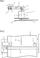
- an inventive hole punch module 1 is shown that a drive motor 2, for example a DC motor, having an eccentric 3, which performs a rotational movement 4 in the direction of an arrow.
- This rotational movement 4 is implemented by the eccentric 3 via a rocker arm 5 in an up and down pivotal movement 6.
- An arranged at the end of the rocker arm 5 lifting or punch 7 performs in a linear guide 8, a linear movement 9 and moves up and down in a die 10, where it is an intermediate Paper, document, folding plan, folded paper or the like, hereinafter referred to briefly as the printing medium 11, at predetermined locations or positions arbitrary, specifiable number successive hole.
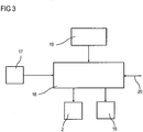
- FIG. 2 shows the inventive arrangement of the punch module 1 in the transport, for example, a printing, stacking, folding device or the like, not shown, hereinafter referred to as printing medium processing device.
- the running on a guide 12 of the transport path printing medium 11 with a stapling and / or hole edge 13 is detected by a rubberized transport roller 14 and held firmly.
- the transport roller 14 is driven by a stepper motor 15, so that the printing medium 11 can be positioned very accurately in the transport direction 16.
- the reflex sensor 17 detects the beginning of the print medium 11, with the help of the stepping motor 15, the exact predetermined Hole positions for the printing medium 11 are approached, as described below with reference to FIG. 3 is described.
- the punch module 1 may be integrated, for example, in the transport path of the printing medium 11 in the region of the output or the output of the printing medium processing device.
- FIG. 3 a central control device 18 is shown, which receives the signal from the reflex sensor 17, which signals the print medium leading edge. Thereafter, the control device 18 controls the stepping motor 15 for positioning the printing medium 11 until the first predetermined hole position is reached. Then, the drive motor 2 is driven, which causes the perforation in the manner described above. Then again the stepper motor 15 for onward transport and driven again positioning of the printing medium 11 until the position for the next Abheftloch is reached, so that the drive motor 2 can again perform the perforation in the described manner. This is repeated until all required or desired bookholes have been created. Finally, the printing medium 11 is further transported on the transport path to the output of the printing medium processing device.
- the desired and required values such as, for example, the size of the printing medium 11, the number of stitch holes and / or desired hole positions, are recorded and input to the control device 18, unless they are detected by sensors.
- Control commands 20 which signal, for example, that a print medium 11 is in the transport path to the print medium output, are transmitted from a central processing unit (not shown) of the print medium processing device, so that in the near future the reflex sensor 17 must detect the leading edge of the print medium 11; i.e. he is released.
- the control commands 20 can also contain values such as, for example, the size of the print medium 11, so that an automatic transfer to the control device 18 can take place.
- the hole punch module 1 of the invention can produce any hole pattern. It has a simple and modular structure and can also be retrofitted in the transport path to a paper output of a printing, stacking, folding machine or the like. There is only a single lifting or punch 7, which is driven via the rocker arm 5 by a DC motor 2 with an eccentric 3 or eg by a solenoid and thus makes a simple linear movement 9. The punch 7 slides in the linear guide 8 and moves into a perforated Sheet metal plate, which acts as a die 10. The punch module 1 is thus no longer positioned to the printing medium 11, but the positioning is exactly the opposite - the printing medium 11 is aligned to the punch module 1 or aligned on the punch module 1 transported to the desired hole positions.
- the printing medium 11 for example a folded plan, is aligned before punching at a corresponding edge in the folding machine and transported further by different rubberized rollers. These rubber rollers firmly engage the folding plan, so that positioning the punch module 1 toward the paper transversely to the transporting direction 16 becomes unnecessary.
- the punch module 1 itself has its own rubberized transport roller 14, which positions the folding plan in the transport direction 16 to the punch 7.
- the rubberized transport roller 14 is driven by a stepper motor 15.
- the seated at the height of the punch 7 reflex sensor 17 detects the leading edge of the folding sheet. From here, the exact hole position is approached by means of the stepping motor 15.
- binding margin holes are at least two firmly positioned holes for filing the document created in a folder.
- the binding margin hole punch sits behind the paper output of the folding machine. Each of the punches is driven by a separate electromagnet. An orientation in transport transverse direction must be done by means of a pivotable stop.
- any number of perforations can be created at any distance for filing the print medium 11 in a folder. Any conceivable hole pattern can be generated, even a uniform perforation over the entire length of the stapling and / or hole edge 13 is possible.
- the punch module 1 according to the invention is integrated in the transport path to the paper output and can be retrofitted at any time.
- the single punch is driven by a DC motor 2 with an eccentric 3 via a rocker arm 5.
- the punch module 1 is positioned so that no alignment transverse to the transport direction 16 is required.
- the exact positioning in the transport direction 16 take over a gummed transport roller 14 driven by a stepper motor 15 and sensors 17 in conjunction with the central control device 18.
Landscapes
- Life Sciences & Earth Sciences (AREA)
- Forests & Forestry (AREA)
- Engineering & Computer Science (AREA)
- Mechanical Engineering (AREA)
- Folding Of Thin Sheet-Like Materials, Special Discharging Devices, And Others (AREA)
- Perforating, Stamping-Out Or Severing By Means Other Than Cutting (AREA)
Description
- Die Erfindung betrifft eine Vorrichtung zum Lochen eines Heft- und/oder Lochrandes eines Druckmediums mit mindestens zwei Löchern, wobei die Vorrichtung einer Druckmedium-Ausgabe einer Druckmedium-Verarbeitungsvorrichtung zugeordnet ist.
- Bisher bekannte Vorrichtungen zum Lochen werden als 2-fach, 4-fach oder aber 3-fach-Locher gefertigt. D.h. diese Locher weisen 2 oder 4 oder 3 Lochstempel auf. Diese Locher können in Abhängigkeit der Abstände der einzelnen Lochstempel zueinander nur das ihnen jeweils vorgegebene entsprechende Lochbild produzieren. Soll von einer 2-fach bzw. 4-fach Lochung auf eine 3-fach Lochung übergegangen werden, so muss der 2-fach bzw. 4-fach Locher gegen einen 3-fach Locher aufwändig ausgetauscht werden. Die bekannten Locher werden in zwei Ebenen zum Druckmedium wie z.B. einem Dokument, Faltplan, Papierstapel oder dgl. hin bewegt und positioniert. Diese Positionierung bedeutet einen komplizierten und vor allem teuren Aufbau mit entsprechender Mess- und Positionierungssteuerung.
- Durch die
JP H06 126699 A - Aus der
US 2010/003108 A1 ist eine eingangs beschriebene Lochervorrichtung bekannt, die mit einem 2-, 3- oder 4-fach Locher arbeitet, wobei das Druckmedium zur Vorrichtung zum Lochen des Heft- und / oder Lochrandes derart positionierbar ist, dass der Abstand der Lochung vom Rand des Druckmediums einstellbar ist. Der Abstand der Löcher zueinander ist fest eingestellt. Durch Verschieben der Vorrichtung zum Lochen eines Heft- und / oder Lochrandes zum Druckmedium kann die Position der Löcher bzw. Kerben längs des Lochrandes bestimmt werden. Neben den aufwendigen zwei bis vier in festem Abstand zueinander vorgesehen Locher Modulen, ist auch hier eine aufwendige Verschiebeeinheit für die Locher Module, die ebenfalls eine aufwendige Medienzuführung zum Betätigen der Locher Module notwendig macht vorgesehen. Die Positionierung des Druckmediums zu den Locher Modulen dient lediglich der Einstellung des Abstandes der Löcher vom Rand des Druckmediums. - Aus der
DE 42 39 750 C2 ist eine Vorrichtung zum Lochen des seitlichen Heftrandes gefalteter Papierbogen, insbesondere großformatige Zeichnungen, bekannt die einen in einem Gehäuse angeordneten, durch Elektromagneten betätigbaren Heftrand-Locher aufweist, der sich an die Papierausgabe einer Faltmaschine anschließt. Im Innern des Gehäuses weist die Lochvorrichtung einen Führungskanal mit seitlichen Führungsorganen zur Aufnahme der Längsränder der von der Faltmaschine ausgegebenen Papierbogen sowie ein dessen Einschubweg begrenzenden schwenkbaren Anschlag zur Ausrichtung in Transportquerrichtung auf. - Der Heftrand-Locher weist je nach gewünschter Lochart eine entsprechende Zahl von Lochstempeln auf, kann z.B. zwei oder vier Lochstempel mit zugehörigen Matrizen zur Lochung besitzen, die durch eine entsprechende Anzahl an parallel geschalteten Elektromagneten betätigt werden. Es werden also für mindestens zwei Löcher zwei fest positionierte Lochstempel benötigt. Der Heftrand-Locher sitzt hinter der Papierausgabe der Faltmaschine. Jeder der Lochstempel wird durch einen Elektromagneten betätigt.
- Die
DE 10 2006 037 432 offenbart ein Verfahren sowie eine Vorrichtung zur Herstellung mindestens einer Fensteröffnung in einem Sicherheits- oder Wertdokument, wobei die Fensteröffnung anschließend mit Folienelementen abgedeckt wird. Zur Herstellung der Fensteröffnung wird ein langgestrecktes Substrat von einer Rolle abgewickelt, virtuell in Papierbogenabschnitte unterteilt, und das Substrat mit mindestens einem Wasserzeichen pro virtuellem Abschnitt versehen. Über eine Sensoreinheit wird das Wasserzeichen erfasst und aufgrund vorgegebener Positionsdaten wird dann die Fensteröffnung pro virtuellem Papierabschnitt gestanzt. Weder sind mindestens zwei Fensteröffnungen pro virtuellem Papierbogenabschnitt noch ist vorgesehen dieser Fensteröffnungen als Heft- oder Lochrand zu verwenden. - Die
DE 689 15 129 T2 offenbart einen Kartenlocher mittels dessen Wertkarten entwertet werden können. Damit die Entwertung exakt erfolgt, müssen die Positionen auf der Karte, an welcher gelocht wird, auch exakt angefahren werden. Dabei wird jedoch nur ein Loch zum Entwerten der Karte gestanzt. Weder die Erstellung von mindestens zwei Löchern noch die Verwendung der Löcher als Heft- oder Lochrand sind angeregt. - Die Erfindung geht von der Aufgabe aus, eine Vorrichtung der eingangs genannten Art derart auszubilden, dass auf einfache Weise variable Lochungen mit unterschiedlichen Abständen und vielfachen Lochbildern der Abheftlöcher ermöglicht werden.
- Die Aufgabe wird erfindungsgemäß für eine Vorrichtung der eingangs genannten Art durch die im Patentanspruch 1 angegebenen Merkmale gelöst. Vorteilhafte Ausbildungen sind in den abhängigen Patentansprüchen angegeben.
- Eine derartige Vorrichtung kann beispielsweise in einem Kanal als Transportweg zu einem Ablagefach zur Dokumentenausgabe gemäß der in der
EP 0 354 176 B1 beschriebenen Faltmaschine als Papierverarbeitungsvorrichtung eingesetzt werden. - Durch den erfindungsgemäßen Aufbau werden variable Lochungen mit unterschiedlichen Lochabständen und vielfachen Lochbildern der Abheftlöcher mittels nur einem einfach aufgebauten, kostengünstig herzustellenden, und leicht nachrüstbaren Lochstempel ermöglicht. Es könnte zwar nur ein Loch vorgesehen sein, die Lochungen sollen aber die bekannten zwei oder vier Abheftlöcher umfassen. Es lässt sich damit aber auch die aus Amerika bekannte, andere Abstände der Löcher zueinander aufweisende 3-fach Lochung erzielen. Es können aber auch in Anzahl und Abstand beliebige Lochbilder z.B. zur Erstellung eines Lochrandes mit dem erfindungsgemäßen Locher Modul erzeugt werden. Je nachdem welches beliebige Lochbild gewünscht wird, kann die Steuer-/Regel-vorrichtung das Druckmedium über eine entsprechende Beeinflussung des Antriebs der Transportwalze wunschgemäß zum Locher Modul positionieren.
- Erfindungsgemäß kann die Vorrichtung im Transportweg zur Druckmedium-Ausgabe der Druckmedium- Verarbeitungsvorrichtung integriert sein bzw. integrierbar sein.
- Damit braucht nur ein Locher Modul mit einem Hub- oder Lochstempel vorgesehen werden, um beliebige Lochbilder erstellen zu können, wobei das Locher Modul leicht und kostengünstig auch nachrüstbar ist.
- Es hat sich als vorteilhaft erwiesen, wenn der Hub- oder Lochstempel über einen Kipphebel von einem Antriebsmotor, beispielweise einem Gleichstrommotor mit einem Exzenter, oder einem Hubmagneten oder dergleichen angetrieben wird und mit einer einfachen Linearbewegung in eine Matrize eingreift.
- Erfindungsgemäß kann der Hub- oder Lochstempel von einer Linearführung geführt und die Matrize eine gelochte Blechplatte sein.
- In vorteilhafter Weise kann die Transportwalze gummiert ausgebildet und/oder von einem Schrittmotor oder einem anderen positionsgeregeltem Antrieb wie zum Beispiel einem über eine Impulsscheibe geregelten Gleichstrommotor angetrieben sein.
- Erfindungsgemäß ist ein Sensor, insbesondere ein Reflexsensor, zur Detektion der Blattvorderkante des Dokuments in Transportrichtung auf Höhe des Lochstempels angeordnet.
- Die Vorrichtung lässt sich in vorteilhafter Weise bei einer Druck-, Stapel-, Faltvorrichtung oder dgl. als Druckmedium- Verarbeitungsvorrichtung im Transportweg zur Druckmedium- Ausgabe einsetzen.
- Es hat sich als vorteilhaft erwiesen, wenn eine Steuer-/Regelvorrichtung vorgesehen ist, an welcher der Sensor, der Antriebsmotor und/oder der Schrittmotor angeschlossen sind.
- Erfindungsgemäß kann eine Eingabevorrichtung zur Erfassung der Größe des Dokuments, Anzahl der Abheftlöcher und/oder Lochpositionen mit der Steuer-/Regelvorrichtung verbunden sein.
- Die Erfindung ist nachfolgend anhand von in der Zeichnung dargestellten Ausführungsbeispielen näher erläutert. Es zeigen:
- Figur 1
- ein erfindungsgemäßes Locher Modul,
- Figur 2
- die Anordnung des Locher Moduls gemäß
Figur 1 in einer im Transportweg zur Druckmedium Ausgabe einer Druckmedium Verarbeitungsvorrichtung angeordneten Vorrichtung zum Lochen, und - Figur 3
- eine Steuervorrichtung zur Steuerung des Locher Moduls.
- In der
Figur 1 ist ein erfindungsgemäßes Locher Modul 1 dargestellt, dass einen Antriebsmotor 2, beispielsweise einen Gleichstrommotor, mit einem Exzenter 3 aufweist, der in Richtung eines Pfeils eine Drehbewegung 4 ausführt. Diese Drehbewegung 4 wird durch den Exzenter 3 über einen Kipphebel 5 in eine auf und ab gerichtete Schwenkbewegung 6 umgesetzt. Ein an dem Ende des Kipphebels 5 angeordneter Hub- oder Lochstempel 7 vollführt in einer Linearführung 8 eine Linearbewegung 9 und fährt auf und ab in eine Matrize 10, wobei er ein dazwischenliegendes Papier, Dokument, Faltplan, gefalteten Papierstapel oder dergleichen, im Weiteren kurz Druckmedium 11 genannt, an vorbestimmten Stellen oder Positionen beliebiger, vorgebbarer Anzahl aufeinander folgend locht. - Die
Figur 2 zeigt die erfindungsgemäße Anordnung des Locher Moduls 1 im Transportweg beispielsweise einer nicht dargestellten Druck-, Stapel-, Faltvorrichtung oder dgl., im Weiteren Druckmedium Verarbeitungsvorrichtung genannt. Das auf einer Führung 12 des Transportwegs laufende Druckmedium 11 mit einem Heft- und/oder Lochrand 13 wird von einer gummierten Transportwalze 14 erfasst und fest gehalten. Die Transportwalze 14 wird von einem Schrittmotor 15 angetrieben, so dass das Druckmedium 11 sehr genau in Transportrichtung 16 positioniert werden kann. - Ein in Transportrichtung 16 auf Höhe des Lochstempels 7 sitzender Sensor, beispielsweise ein Reflexsensor 17, erkennt die Vorderkante des in die Vorrichtung eintretenden Druckmediums 11. Wenn der Reflexsensor 17 den Anfang des Druckmediums 11 detektiert hat, kann mit Hilfe des Schrittmotors 15 die genauen vorher festgelegten Lochpositionen für das Druckmedium 11 angefahren werden, wie nachfolgend anhand der
Figur 3 beschrieben wird. - Das Locher Modul 1 kann beispielsweise in den Transportweg des Druckmediums 11 im Bereich des Ausgangs oder der Ausgabe der Druckmedium Verarbeitungsvorrichtung integriert sein.
- In der
Figur 3 ist eine zentrale Steuervorrichtung 18 dargestellt, die von dem Reflexsensor 17 das Signal erhält, das die Druckmedium Vorderkante signalisiert. Daraufhin steuert die Steuervorrichtung 18 den Schrittmotor 15 zur Positionierung des Druckmediums 11, bis die erste vorgegebene Lochposition erreicht ist. Dann wird der Antriebsmotor 2 angesteuert, der die Lochung in oben beschriebener Weise bewirkt. Darauf wird wieder der Schrittmotor 15 zum Weitertransport und erneuter Positionierung des Druckmediums 11 angesteuert, bis die Position für das nächste Abheftloch erreicht ist, so dass der Antriebsmotor 2 wieder die Lochung in beschriebener Weise durchführen kann. Dies wiederholt sich, bis alle erforderlichen bzw. gewünschten Abheftlöcher erstellt sind. Abschließend wird das Druckmedium 11 weiter auf dem Transportweg zum Ausgang der Druckmedium Verarbeitungsvorrichtung transportiert. - Mittels einer Eingabevorrichtung 19 werden die gewünschten und erforderlichen Werte wie beispielsweise Größe des Druckmediums 11, Anzahl der Abheftlöcher und/oder gewünschte Lochpositionen in die Steuervorrichtung 18 erfasst und eingegeben, sofern sie nicht durch Sensoren detektiert werden.
- Von einer nicht dargestellten Zentraleinheit der Druckmedium Verarbeitungsvorrichtung werden Steuerbefehle 20 an die Steuervorrichtung 18 übermittelt, die beispielsweise signalisieren, dass sich ein Druckmedium 11 auf dem Transportweg zur Druckmedium Ausgabe befindet, so dass demnächst der Reflexsensor 17 die Vorderkante des Druckmediums 11 detektieren muss; d.h. er wird freigegeben. Die Steuerbefehle 20 können aber auch Werte wie beispielsweise Größe des Druckmediums 11 enthalten, so dass eine automatische Übernahme zur Steuervorrichtung 18 erfolgen kann.
- Gegenüber den bisherigen 2-fach oder 4-fach Heftrand-Lochern bzw. den 3-fach Heftrand-Lochern, die nur diese entsprechenden Lochbilder erzeugen können, kann das erfindungsgemäße Locher Modul 1 beliebige Lochmuster erzeugen. Es weist einen einfachen und modularen Aufbau und kann auch im Transportweg zu einer Papierausgabe einer Druck-, Stapel-, Faltmaschine oder dgl. nachgerüstet werden. Es existiert nur noch ein einziger Hub- oder Lochstempel 7, der über den Kipphebel 5 von einem Gleichstrommotor 2 mit einem Exzenter 3 oder z.B. von einem Hubmagneten angetrieben wird und so eine einfache Linearbewegung 9 macht. Der Lochstempel 7 gleitet in der Linearführung 8 und fährt in eine gelochte Blechplatte, die als Matrize 10 fungiert. Das Locher Modul 1 wird somit nicht mehr zum Druckmedium 11 hin positioniert, sondern die Positionierung erfolgt genau umgekehrt - das Druckmedium 11 wird zum Locher Modul 1 ausgerichtet bzw. ausgerichtet am Locher Modul 1 bis zu den gewünschten Lochpositionen vorbeitransportiert.
- Das Druckmedium 11, beispielsweise ein gefalteter Plan, wird vor dem Lochen an einer entsprechenden Kante in der Faltmaschine ausgerichtet und von unterschiedlichen gummierten Walzen weiter transportiert. Diese Gummiwalzen haben den Faltplan fest im Eingriff, sodass ein Positionieren des Locher Moduls 1 zum Papier quer zur Transportrichtung 16 hin überflüssig wird.
- Das Locher Modul 1 selber besitzt eine eigene gummierte Transportwalze 14, die den Faltplan in Transportrichtung 16 zum Lochstempel 7 positioniert. Um hier einen exakten Transport und somit den späteren richtigen Abstand der Abheftlöcher zu gewährleisten, wird die gummierte Transportwalze 14 von einem Schrittmotor 15 angetrieben.
- Der auf Höhe des Lochstempels 7 sitzende Reflexsensor 17 erkennt die Blattvorderkante des Faltplans. Ab hier wird mit Hilfe des Schrittmotors 15 die genaue Lochposition angefahren.
- Durch den einzelnen Lochstempel 7, an dem das zu lochende Druckmedium 11 vorbei transportiert wird, können beliebig viele und unterschiedliche Lochbilder produziert werden.
- Diese Flexibilität macht den erfindungsgemäßen Heftrand-Locher beispielsweise für Händler investitionssicher, da nicht im Voraus entschieden werden muss, ob ein 2-fach, 3-fach, 4-fach oder überhaupt ein Locher bestellt wird. Es muss nur das eine Locher Modul auf Lager gehalten werden, wodurch sich die Option, eine Vorrichtung zum Lochen einzusetzen erheblich vergünstigt.
- Bei der aus der
DE 42 39 750 C2 bekannten Heftrand-Locher werden mindestens zwei fest positionierte Lochungen zum Abheften des Dokuments in einem Ordner erstellt. Der Heftrand-Locher sitzt hinter der Papierausgabe der Faltmaschine. Jeder der Lochstempel wird von einem getrennten Elektromagneten angetrieben. Eine Ausrichtung in Transportquerrichtung muss mittels eines schwenkbaren Anschlags erfolgen. - Mit dem erfindungsgemäßen Locher Modul 1 dagegen können beliebig viele Lochungen mit beliebigem Abstand zum Abheften des Druckmediums 11 in einem Ordner erstellt werden. Jedes erdenkliche Lochbild kann erzeugt werden, auch eine gleichmäßige Perforierung über die gesamte Länge des Heft- und/oder Lochrandes 13 ist möglich.
- Das erfindungsgemäße Locher Modul 1 ist im Transportweg zur Papierausgabe integriert und kann jederzeit nachgerüstet werden. Der einzige Lochstempel wird von einem Gleichstrommotor 2 mit einem Exzenter 3 über einen Kipphebel 5 angetrieben.
- Das erfindungsgemäße Locher Modul 1 ist so positioniert, dass keine Ausrichtung quer zur Transportrichtung 16 erforderlich ist. Die genaue Positionierung in Transportrichtung 16 übernehmen eine von einem Schrittmotor 15 angetriebene gummierte Transportwalze 14 und Sensoren 17 in Verbindung mit der zentralen Steuervorrichtung 18.
-
- 1
- Locher Modul
- 2
- Antriebsmotor
- 3
- Exzenter
- 4
- Drehbewegung
- 5
- Kipphebel
- 6
- Schwenkbewegung
- 7
- Hub- oder Lochstempel
- 8
- Linearführung
- 9
- Linearbewegung
- 10
- Matrize
- 11
- Druckmedium
- 12
- Führung
- 13
- Lochrand
- 14
- gummierte Transportwalze
- 15
- Schrittmotor
- 16
- Transportrichtung
- 17
- Reflexsensor
- 18
- Steuervorrichtung
- 19
- Eingabevorrichtung
- 20
- Steuerbefehle
Claims (3)
- Druckmedium-.Verarbeitungsvorrichtung mit einer Vorrichtung zum Lochen eines Heft- und/oder Lochrandes (13) eines Druckmediums (11) mit mindestens zwei Löchern, wobei die Vorrichtung zum Lochen der Druckmedium- Ausgabe der Druckmedium- Verarbeitungsvorrichtung zugeordnet ist, und ein ortsfest angeordnetes, nur einen Hub- oder Lochstempel (7) aufweisendes Locher Modul (1) zur nacheinander erfolgenden Lochung der mindestens zwei Abheftlöcher an vorgebbaren Lochpositionen im Heft- und/oder Lochrand (13) des Druckmediums (11) aufweist,
wobei mindestens eine Transportwalze (14) für das Druckmedium (11) vorgesehen ist, mittels derer das Druckmedium (11) zum Locher Modul (1) an den mindestens zwei vorgebbaren Lochpositionen positionierbar ist, und der Transportwalze (14) eine Steuer-/Regelvorrichtung (18) zugeordnet ist, über welche die Positionierung des Druckmediums (11) zum Locher Modul (1) an die mindestens zwei vorgebbaren Lochpositionen steuer- bzw. regelbar ist. - Vorrichtung nach Anspruch 1,
dadurch gekennzeichnet,
dass die Vorrichtung im Transportweg zur Druckmedium- Ausgabe der Druckmedium- Verarbeitungsvorrichtung integriert bzw. integrierbar ist. - Vorrichtung nach Anspruch 1 oder 2,
dadurch gekennzeichnet,
dass der Hub- oder Lochstempel (7) des Locher Moduls (1) über einen Kipphebel (5) von einem Antriebsmotor (2) angetrieben wird und mit einer einfachen Linearbewegung (9) in eine Matrize (10) eingreift.
Applications Claiming Priority (2)
| Application Number | Priority Date | Filing Date | Title |
|---|---|---|---|
| DE102014204663.7A DE102014204663A1 (de) | 2014-03-13 | 2014-03-13 | Vorrichtung zum Lochen eines Heft- und/oder Lochrandes eines Druckmediums |
| PCT/EP2015/000523 WO2015135643A1 (de) | 2014-03-13 | 2015-03-09 | Vorrichtung zum lochen eines heft- und/oder lochrandes eines druckmediums |
Publications (2)
| Publication Number | Publication Date |
|---|---|
| EP3116695A1 EP3116695A1 (de) | 2017-01-18 |
| EP3116695B1 true EP3116695B1 (de) | 2019-09-18 |
Family
ID=52633221
Family Applications (1)
| Application Number | Title | Priority Date | Filing Date |
|---|---|---|---|
| EP15708735.4A Active EP3116695B1 (de) | 2014-03-13 | 2015-03-09 | Vorrichtung zum lochen eines heft- und/oder lochrandes eines druckmediums |
Country Status (3)
| Country | Link |
|---|---|
| EP (1) | EP3116695B1 (de) |
| DE (1) | DE102014204663A1 (de) |
| WO (1) | WO2015135643A1 (de) |
Families Citing this family (1)
| Publication number | Priority date | Publication date | Assignee | Title |
|---|---|---|---|---|
| CN106363696A (zh) * | 2016-08-29 | 2017-02-01 | 中航动力股份有限公司 | 一种橡胶样品的自动裁样方法及装置 |
Citations (1)
| Publication number | Priority date | Publication date | Assignee | Title |
|---|---|---|---|---|
| DE19729918A1 (de) * | 1997-07-04 | 1999-01-07 | Bundesdruckerei Gmbh | Sicherheits- und/oder Wertdokument |
Family Cites Families (6)
| Publication number | Priority date | Publication date | Assignee | Title |
|---|---|---|---|---|
| EP0354176B1 (de) | 1988-07-28 | 1992-12-09 | Otto Dipl.-Ing. Bay | Maschine zum Falten von Papierbogen |
| JPH02148189A (ja) * | 1988-11-29 | 1990-06-07 | Nippon Conlux Co Ltd | カード穿孔装置 |
| JP3024249B2 (ja) * | 1991-03-30 | 2000-03-21 | ぺんてる株式会社 | 電動式パンチ装置 |
| DE4239750C2 (de) | 1991-11-28 | 1994-12-15 | Bay Otto | Vorrichtung zum Lochen von Papierbogen |
| DE102006037432C5 (de) * | 2006-08-09 | 2014-08-14 | Leonhard Kurz Gmbh & Co. Kg | Verfahren zur Herstellung mindestens einer Fensteröffnung in einem langgestreckten Papiersubstrat, sowie Vorrichtung |
| JP4609538B2 (ja) * | 2008-07-01 | 2011-01-12 | コニカミノルタビジネステクノロジーズ株式会社 | 切欠き形成装置、製本装置及び製本システム |
-
2014
- 2014-03-13 DE DE102014204663.7A patent/DE102014204663A1/de not_active Withdrawn
-
2015
- 2015-03-09 EP EP15708735.4A patent/EP3116695B1/de active Active
- 2015-03-09 WO PCT/EP2015/000523 patent/WO2015135643A1/de not_active Ceased
Patent Citations (1)
| Publication number | Priority date | Publication date | Assignee | Title |
|---|---|---|---|---|
| DE19729918A1 (de) * | 1997-07-04 | 1999-01-07 | Bundesdruckerei Gmbh | Sicherheits- und/oder Wertdokument |
Also Published As
| Publication number | Publication date |
|---|---|
| WO2015135643A1 (de) | 2015-09-17 |
| DE102014204663A1 (de) | 2015-09-17 |
| EP3116695A1 (de) | 2017-01-18 |
Similar Documents
| Publication | Publication Date | Title |
|---|---|---|
| EP2727869B1 (de) | Vorrichtung und Verfahren zum Falzen von Druckbogen | |
| EP1919641A1 (de) | Stanzvorrichtung mit zuführeinrichtung | |
| DE202008006688U1 (de) | Drei-Wege-Weiche zum Umleiten von blattförmigen Medien | |
| DE2618439C2 (de) | Transporteinrichtung für die Auswertung von Identifizierungskarten | |
| DE102018101793A1 (de) | Teilezuführeinrichtung und Teilezuführroboter, der diese umfasst | |
| EP1211000A2 (de) | Verfahren zum sementartigen Biegen von Drahtbindeelementen | |
| EP3931817B1 (de) | Drucker zum bedrucken von markierer-karten mit markierern zum markieren elektrischer geräte | |
| WO2015135643A1 (de) | Vorrichtung zum lochen eines heft- und/oder lochrandes eines druckmediums | |
| EP2106351A1 (de) | Verfahren und vorrichtung zum beschriften eines heftartigen gegenstandes in einer beschriftungsstation | |
| EP3406456A1 (de) | Klebebinder | |
| EP1238930B1 (de) | Bogentrennvorrichtung | |
| EP2119569A2 (de) | Sammelhefter mit variabler Kettenteilung | |
| DE10201382A1 (de) | Einstellbare Nadeln für eine Bogentrennvorrichtung | |
| DE60211113T2 (de) | Stanzvorrichtung für eine Buchbinde-Nähmaschine | |
| DE10248688B4 (de) | Vorrichtung zur Erzeugung von unterschiedlichen Lochbildern in blattförmigen Bedruckstoffen | |
| DE10392550T5 (de) | Automatisierte Stanzmaschine zum Perforieren von Blattstapel | |
| BE1031113B1 (de) | Aufstaplungsvorrichtung zum Aufstapeln von Substraten | |
| EP1387811A2 (de) | Vorrichtung und verfahren zur eingabe und ablage von banknoten | |
| EP2386389B1 (de) | Verfahren und Vorrichtung zum Längsperforieren einer bewegten Materialbahn | |
| EP1211098A2 (de) | Verfahren zum Herstellen von Broschüren beliebiger Formate und Dicken mittels Drahtkammbindung | |
| EP1281648A2 (de) | Vorrichtung zum Transport von blattförmigen Bedruckstoffen | |
| EP3530481B1 (de) | Vorrichtung zur herstellung einer perforation in einem sicherheitsdokument | |
| DE10329625B4 (de) | Kuvertiermaschine | |
| WO2024120780A1 (de) | Aufstaplungsvorrichtung zum aufstapeln von substraten | |
| EP2060522A1 (de) | Vorrichtung zum Falzen von Flachprodukten |
Legal Events
| Date | Code | Title | Description |
|---|---|---|---|
| STAA | Information on the status of an ep patent application or granted ep patent |
Free format text: STATUS: THE INTERNATIONAL PUBLICATION HAS BEEN MADE |
|
| PUAI | Public reference made under article 153(3) epc to a published international application that has entered the european phase |
Free format text: ORIGINAL CODE: 0009012 |
|
| STAA | Information on the status of an ep patent application or granted ep patent |
Free format text: STATUS: REQUEST FOR EXAMINATION WAS MADE |
|
| 17P | Request for examination filed |
Effective date: 20160830 |
|
| AK | Designated contracting states |
Kind code of ref document: A1 Designated state(s): AL AT BE BG CH CY CZ DE DK EE ES FI FR GB GR HR HU IE IS IT LI LT LU LV MC MK MT NL NO PL PT RO RS SE SI SK SM TR |
|
| AX | Request for extension of the european patent |
Extension state: BA ME |
|
| RIN1 | Information on inventor provided before grant (corrected) |
Inventor name: SPORK, MORITZ Inventor name: MUELLER, MARTIN |
|
| DAV | Request for validation of the european patent (deleted) | ||
| DAX | Request for extension of the european patent (deleted) | ||
| STAA | Information on the status of an ep patent application or granted ep patent |
Free format text: STATUS: EXAMINATION IS IN PROGRESS |
|
| 17Q | First examination report despatched |
Effective date: 20170907 |
|
| GRAP | Despatch of communication of intention to grant a patent |
Free format text: ORIGINAL CODE: EPIDOSNIGR1 |
|
| STAA | Information on the status of an ep patent application or granted ep patent |
Free format text: STATUS: GRANT OF PATENT IS INTENDED |
|
| INTG | Intention to grant announced |
Effective date: 20190424 |
|
| GRAS | Grant fee paid |
Free format text: ORIGINAL CODE: EPIDOSNIGR3 |
|
| GRAA | (expected) grant |
Free format text: ORIGINAL CODE: 0009210 |
|
| STAA | Information on the status of an ep patent application or granted ep patent |
Free format text: STATUS: THE PATENT HAS BEEN GRANTED |
|
| AK | Designated contracting states |
Kind code of ref document: B1 Designated state(s): AL AT BE BG CH CY CZ DE DK EE ES FI FR GB GR HR HU IE IS IT LI LT LU LV MC MK MT NL NO PL PT RO RS SE SI SK SM TR |
|
| REG | Reference to a national code |
Ref country code: GB Ref legal event code: FG4D Free format text: NOT ENGLISH |
|
| REG | Reference to a national code |
Ref country code: CH Ref legal event code: EP |
|
| REG | Reference to a national code |
Ref country code: DE Ref legal event code: R096 Ref document number: 502015010393 Country of ref document: DE |
|
| REG | Reference to a national code |
Ref country code: AT Ref legal event code: REF Ref document number: 1180748 Country of ref document: AT Kind code of ref document: T Effective date: 20191015 |
|
| REG | Reference to a national code |
Ref country code: IE Ref legal event code: FG4D Free format text: LANGUAGE OF EP DOCUMENT: GERMAN |
|
| REG | Reference to a national code |
Ref country code: NL Ref legal event code: MP Effective date: 20190918 |
|
| PG25 | Lapsed in a contracting state [announced via postgrant information from national office to epo] |
Ref country code: SE Free format text: LAPSE BECAUSE OF FAILURE TO SUBMIT A TRANSLATION OF THE DESCRIPTION OR TO PAY THE FEE WITHIN THE PRESCRIBED TIME-LIMIT Effective date: 20190918 Ref country code: BG Free format text: LAPSE BECAUSE OF FAILURE TO SUBMIT A TRANSLATION OF THE DESCRIPTION OR TO PAY THE FEE WITHIN THE PRESCRIBED TIME-LIMIT Effective date: 20191218 Ref country code: HR Free format text: LAPSE BECAUSE OF FAILURE TO SUBMIT A TRANSLATION OF THE DESCRIPTION OR TO PAY THE FEE WITHIN THE PRESCRIBED TIME-LIMIT Effective date: 20190918 Ref country code: NO Free format text: LAPSE BECAUSE OF FAILURE TO SUBMIT A TRANSLATION OF THE DESCRIPTION OR TO PAY THE FEE WITHIN THE PRESCRIBED TIME-LIMIT Effective date: 20191218 Ref country code: FI Free format text: LAPSE BECAUSE OF FAILURE TO SUBMIT A TRANSLATION OF THE DESCRIPTION OR TO PAY THE FEE WITHIN THE PRESCRIBED TIME-LIMIT Effective date: 20190918 Ref country code: LT Free format text: LAPSE BECAUSE OF FAILURE TO SUBMIT A TRANSLATION OF THE DESCRIPTION OR TO PAY THE FEE WITHIN THE PRESCRIBED TIME-LIMIT Effective date: 20190918 |
|
| REG | Reference to a national code |
Ref country code: LT Ref legal event code: MG4D |
|
| PG25 | Lapsed in a contracting state [announced via postgrant information from national office to epo] |
Ref country code: LV Free format text: LAPSE BECAUSE OF FAILURE TO SUBMIT A TRANSLATION OF THE DESCRIPTION OR TO PAY THE FEE WITHIN THE PRESCRIBED TIME-LIMIT Effective date: 20190918 Ref country code: GR Free format text: LAPSE BECAUSE OF FAILURE TO SUBMIT A TRANSLATION OF THE DESCRIPTION OR TO PAY THE FEE WITHIN THE PRESCRIBED TIME-LIMIT Effective date: 20191219 Ref country code: RS Free format text: LAPSE BECAUSE OF FAILURE TO SUBMIT A TRANSLATION OF THE DESCRIPTION OR TO PAY THE FEE WITHIN THE PRESCRIBED TIME-LIMIT Effective date: 20190918 Ref country code: AL Free format text: LAPSE BECAUSE OF FAILURE TO SUBMIT A TRANSLATION OF THE DESCRIPTION OR TO PAY THE FEE WITHIN THE PRESCRIBED TIME-LIMIT Effective date: 20190918 |
|
| PG25 | Lapsed in a contracting state [announced via postgrant information from national office to epo] |
Ref country code: ES Free format text: LAPSE BECAUSE OF FAILURE TO SUBMIT A TRANSLATION OF THE DESCRIPTION OR TO PAY THE FEE WITHIN THE PRESCRIBED TIME-LIMIT Effective date: 20190918 Ref country code: NL Free format text: LAPSE BECAUSE OF FAILURE TO SUBMIT A TRANSLATION OF THE DESCRIPTION OR TO PAY THE FEE WITHIN THE PRESCRIBED TIME-LIMIT Effective date: 20190918 Ref country code: PL Free format text: LAPSE BECAUSE OF FAILURE TO SUBMIT A TRANSLATION OF THE DESCRIPTION OR TO PAY THE FEE WITHIN THE PRESCRIBED TIME-LIMIT Effective date: 20190918 Ref country code: RO Free format text: LAPSE BECAUSE OF FAILURE TO SUBMIT A TRANSLATION OF THE DESCRIPTION OR TO PAY THE FEE WITHIN THE PRESCRIBED TIME-LIMIT Effective date: 20190918 Ref country code: PT Free format text: LAPSE BECAUSE OF FAILURE TO SUBMIT A TRANSLATION OF THE DESCRIPTION OR TO PAY THE FEE WITHIN THE PRESCRIBED TIME-LIMIT Effective date: 20200120 Ref country code: IT Free format text: LAPSE BECAUSE OF FAILURE TO SUBMIT A TRANSLATION OF THE DESCRIPTION OR TO PAY THE FEE WITHIN THE PRESCRIBED TIME-LIMIT Effective date: 20190918 Ref country code: EE Free format text: LAPSE BECAUSE OF FAILURE TO SUBMIT A TRANSLATION OF THE DESCRIPTION OR TO PAY THE FEE WITHIN THE PRESCRIBED TIME-LIMIT Effective date: 20190918 |
|
| PG25 | Lapsed in a contracting state [announced via postgrant information from national office to epo] |
Ref country code: IS Free format text: LAPSE BECAUSE OF FAILURE TO SUBMIT A TRANSLATION OF THE DESCRIPTION OR TO PAY THE FEE WITHIN THE PRESCRIBED TIME-LIMIT Effective date: 20200224 Ref country code: SM Free format text: LAPSE BECAUSE OF FAILURE TO SUBMIT A TRANSLATION OF THE DESCRIPTION OR TO PAY THE FEE WITHIN THE PRESCRIBED TIME-LIMIT Effective date: 20190918 Ref country code: CZ Free format text: LAPSE BECAUSE OF FAILURE TO SUBMIT A TRANSLATION OF THE DESCRIPTION OR TO PAY THE FEE WITHIN THE PRESCRIBED TIME-LIMIT Effective date: 20190918 Ref country code: SK Free format text: LAPSE BECAUSE OF FAILURE TO SUBMIT A TRANSLATION OF THE DESCRIPTION OR TO PAY THE FEE WITHIN THE PRESCRIBED TIME-LIMIT Effective date: 20190918 |
|
| REG | Reference to a national code |
Ref country code: DE Ref legal event code: R097 Ref document number: 502015010393 Country of ref document: DE |
|
| PLBE | No opposition filed within time limit |
Free format text: ORIGINAL CODE: 0009261 |
|
| STAA | Information on the status of an ep patent application or granted ep patent |
Free format text: STATUS: NO OPPOSITION FILED WITHIN TIME LIMIT |
|
| PG2D | Information on lapse in contracting state deleted |
Ref country code: IS |
|
| PG25 | Lapsed in a contracting state [announced via postgrant information from national office to epo] |
Ref country code: DK Free format text: LAPSE BECAUSE OF FAILURE TO SUBMIT A TRANSLATION OF THE DESCRIPTION OR TO PAY THE FEE WITHIN THE PRESCRIBED TIME-LIMIT Effective date: 20190918 Ref country code: IS Free format text: LAPSE BECAUSE OF FAILURE TO SUBMIT A TRANSLATION OF THE DESCRIPTION OR TO PAY THE FEE WITHIN THE PRESCRIBED TIME-LIMIT Effective date: 20200119 |
|
| 26N | No opposition filed |
Effective date: 20200619 |
|
| PG25 | Lapsed in a contracting state [announced via postgrant information from national office to epo] |
Ref country code: SI Free format text: LAPSE BECAUSE OF FAILURE TO SUBMIT A TRANSLATION OF THE DESCRIPTION OR TO PAY THE FEE WITHIN THE PRESCRIBED TIME-LIMIT Effective date: 20190918 |
|
| PG25 | Lapsed in a contracting state [announced via postgrant information from national office to epo] |
Ref country code: MC Free format text: LAPSE BECAUSE OF FAILURE TO SUBMIT A TRANSLATION OF THE DESCRIPTION OR TO PAY THE FEE WITHIN THE PRESCRIBED TIME-LIMIT Effective date: 20190918 |
|
| REG | Reference to a national code |
Ref country code: CH Ref legal event code: PL |
|
| REG | Reference to a national code |
Ref country code: BE Ref legal event code: MM Effective date: 20200331 |
|
| PG25 | Lapsed in a contracting state [announced via postgrant information from national office to epo] |
Ref country code: LU Free format text: LAPSE BECAUSE OF NON-PAYMENT OF DUE FEES Effective date: 20200309 |
|
| PG25 | Lapsed in a contracting state [announced via postgrant information from national office to epo] |
Ref country code: LI Free format text: LAPSE BECAUSE OF NON-PAYMENT OF DUE FEES Effective date: 20200331 Ref country code: IE Free format text: LAPSE BECAUSE OF NON-PAYMENT OF DUE FEES Effective date: 20200309 Ref country code: CH Free format text: LAPSE BECAUSE OF NON-PAYMENT OF DUE FEES Effective date: 20200331 Ref country code: FR Free format text: LAPSE BECAUSE OF NON-PAYMENT OF DUE FEES Effective date: 20200331 |
|
| PG25 | Lapsed in a contracting state [announced via postgrant information from national office to epo] |
Ref country code: BE Free format text: LAPSE BECAUSE OF NON-PAYMENT OF DUE FEES Effective date: 20200331 |
|
| GBPC | Gb: european patent ceased through non-payment of renewal fee |
Effective date: 20200309 |
|
| PG25 | Lapsed in a contracting state [announced via postgrant information from national office to epo] |
Ref country code: GB Free format text: LAPSE BECAUSE OF NON-PAYMENT OF DUE FEES Effective date: 20200309 |
|
| REG | Reference to a national code |
Ref country code: AT Ref legal event code: MM01 Ref document number: 1180748 Country of ref document: AT Kind code of ref document: T Effective date: 20200309 |
|
| PG25 | Lapsed in a contracting state [announced via postgrant information from national office to epo] |
Ref country code: AT Free format text: LAPSE BECAUSE OF NON-PAYMENT OF DUE FEES Effective date: 20200309 |
|
| PG25 | Lapsed in a contracting state [announced via postgrant information from national office to epo] |
Ref country code: TR Free format text: LAPSE BECAUSE OF FAILURE TO SUBMIT A TRANSLATION OF THE DESCRIPTION OR TO PAY THE FEE WITHIN THE PRESCRIBED TIME-LIMIT Effective date: 20190918 Ref country code: MT Free format text: LAPSE BECAUSE OF FAILURE TO SUBMIT A TRANSLATION OF THE DESCRIPTION OR TO PAY THE FEE WITHIN THE PRESCRIBED TIME-LIMIT Effective date: 20190918 Ref country code: CY Free format text: LAPSE BECAUSE OF FAILURE TO SUBMIT A TRANSLATION OF THE DESCRIPTION OR TO PAY THE FEE WITHIN THE PRESCRIBED TIME-LIMIT Effective date: 20190918 |
|
| PG25 | Lapsed in a contracting state [announced via postgrant information from national office to epo] |
Ref country code: MK Free format text: LAPSE BECAUSE OF FAILURE TO SUBMIT A TRANSLATION OF THE DESCRIPTION OR TO PAY THE FEE WITHIN THE PRESCRIBED TIME-LIMIT Effective date: 20190918 |
|
| P01 | Opt-out of the competence of the unified patent court (upc) registered |
Effective date: 20230517 |
|
| PGFP | Annual fee paid to national office [announced via postgrant information from national office to epo] |
Ref country code: DE Payment date: 20260319 Year of fee payment: 12 |