EP3115997B1 - Supraleitende kabeltrasse - Google Patents
Supraleitende kabeltrasse Download PDFInfo
- Publication number
- EP3115997B1 EP3115997B1 EP15758663.7A EP15758663A EP3115997B1 EP 3115997 B1 EP3115997 B1 EP 3115997B1 EP 15758663 A EP15758663 A EP 15758663A EP 3115997 B1 EP3115997 B1 EP 3115997B1
- Authority
- EP
- European Patent Office
- Prior art keywords
- superconducting
- magnetic shield
- shield member
- magnetic field
- pipe
- Prior art date
- Legal status (The legal status is an assumption and is not a legal conclusion. Google has not performed a legal analysis and makes no representation as to the accuracy of the status listed.)
- Active
Links
Images

Classifications
-
- H—ELECTRICITY
- H02—GENERATION; CONVERSION OR DISTRIBUTION OF ELECTRIC POWER
- H02G—INSTALLATION OF ELECTRIC CABLES OR LINES, OR OF COMBINED OPTICAL AND ELECTRIC CABLES OR LINES
- H02G15/00—Cable fittings
- H02G15/34—Cable fittings for cryogenic cables
-
- H—ELECTRICITY
- H02—GENERATION; CONVERSION OR DISTRIBUTION OF ELECTRIC POWER
- H02G—INSTALLATION OF ELECTRIC CABLES OR LINES, OR OF COMBINED OPTICAL AND ELECTRIC CABLES OR LINES
- H02G9/00—Installations of electric cables or lines in or on the ground or water
- H02G9/06—Installations of electric cables or lines in or on the ground or water in underground tubes or conduits; Tubes or conduits therefor
-
- H—ELECTRICITY
- H01—ELECTRIC ELEMENTS
- H01B—CABLES; CONDUCTORS; INSULATORS; SELECTION OF MATERIALS FOR THEIR CONDUCTIVE, INSULATING OR DIELECTRIC PROPERTIES
- H01B12/00—Superconductive or hyperconductive conductors, cables, or transmission lines
- H01B12/16—Superconductive or hyperconductive conductors, cables, or transmission lines characterised by cooling
-
- Y—GENERAL TAGGING OF NEW TECHNOLOGICAL DEVELOPMENTS; GENERAL TAGGING OF CROSS-SECTIONAL TECHNOLOGIES SPANNING OVER SEVERAL SECTIONS OF THE IPC; TECHNICAL SUBJECTS COVERED BY FORMER USPC CROSS-REFERENCE ART COLLECTIONS [XRACs] AND DIGESTS
- Y02—TECHNOLOGIES OR APPLICATIONS FOR MITIGATION OR ADAPTATION AGAINST CLIMATE CHANGE
- Y02E—REDUCTION OF GREENHOUSE GAS [GHG] EMISSIONS, RELATED TO ENERGY GENERATION, TRANSMISSION OR DISTRIBUTION
- Y02E40/00—Technologies for an efficient electrical power generation, transmission or distribution
- Y02E40/60—Superconducting electric elements or equipment; Power systems integrating superconducting elements or equipment
Definitions
- the present invention relates to a superconducting cable line in which a superconducting cable is installed, and to a thermal insulation pipeline suitable for constituent members of the superconducting cable line.
- the present invention relates to a superconducting cable line with a low load on a refrigerator which cools refrigerant.
- the superconducting cable is capable of transmitting a large amount of electric power with a low loss as compared with the existing normal conducting cable (such as OF cable or CV cable for example), and is therefore expected as an energy saving technology. Recently, proof tests have been conducted by installing a superconducting cable and actually transmitting electric power through the superconducting cable.
- a typical superconducting cable includes a cable core having a superconducting layer (a superconducting conductor layer and a superconducting shield layer) formed of a superconducting wire wound in a spiral shape around the outer periphery of a former, the cable core is housed in a thermal insulation pipe, and refrigerant (liquid nitrogen for example) is flown in the thermal insulation pipe to thereby cool the superconducting layer (PTD 1). Since the superconducting shield layer is provided, induced current which is opposite in direction and substantially identical in magnitude to the current flowing in the superconducting conductor layer flows in this superconducting shield layer.
- a superconducting layer a superconducting conductor layer and a superconducting shield layer
- the thermal insulation pipe is generally a double structure pipe having an inner pipe and an outer pipe. A vacuum is produced in a space between the inner pipe and the outer pipe to form a vacuum thermal insulation layer in this space.
- the magnetic field is applied first to the thermal insulation pipe. Since the thermal insulation pipe is generally made of a metal material, there is a possibility that the magnetic field applied to the thermal insulation pipe causes an eddy current and thereby Joule heating, resulting in an eddy current loss.
- the eddy current loss generated in the thermal insulation pipe causes a load on a refrigerator which cools refrigerant with which the inside of the thermal insulation pipe is filled. It is accordingly desired to develop a thermal insulation pipeline and a superconducting cable line with a low load on the refrigerator for refrigerant, even when influenced by an externally applied magnetic field.
- the present invention has been made in view of the above-described circumstances, and an object of the present invention is to provide a superconducting cable line with a low load on a refrigerator which cools refrigerant.
- Another object of the present invention is to provide a thermal insulation pipeline with a low load on a refrigerator which cools refrigerant.
- the present invention is directed to a superconducting cable line according to the independent device claim 1.
- the above-described superconducting cable line exerts a low load on a refrigerator which cools refrigerant, even when influenced by an externally applied magnetic field.
- the above-described thermal insulation pipeline also exerts a low load on a refrigerator which cools refrigerant, even when influenced by an externally applied magnetic field.
- the inventors of the present invention have studied an eddy current loss which is generated in the thermal insulation pipe when influenced by a magnetic field externally applied to the superconducting cable (this magnetic field may hereinafter be referred to as external magnetic field). Since the thermal insulation pipe of the superconducting cable is filled with refrigerant such as liquid nitrogen, the thermal insulation pipe is generally made of a material such as stainless steel which is excellent in resistance to the operating temperature of the superconducting cable. When a magnetic field is applied to a metal material such as stainless steel, an eddy current is generated in the metal material to cause Joule heating, resulting in an eddy current loss.
- the magnetic field which cannot be reduced in the outer pipe is applied through the outer pipe to the inner pipe and thereby generate an eddy current loss in the inner pipe as well.
- the outer pipe is exposed to the external environment (room temperature portion) and the Joule heat due to the eddy current is released toward the room temperature portion, and therefore a resulting influence on the load on a cooling mechanism (refrigerator) which cools refrigerant is small.
- the inner pipe is located to contact the refrigerant (located on the side of a low temperature portion), and therefore the Joule heat due to the eddy current is released toward the refrigerant.
- the eddy current loss generated in the inner pipe exerts a large influence on the load on the refrigerator.
- the eddy current loss generated in the inner pipe should be reduced as much as possible. It was found as a result of the aforementioned FEM analysis that the eddy current loss generated in the inner pipe is approximately 5 to 10 W/m, namely nonnegligibly large. In view of this, it was studied to shield the superconducting cable from the influence of the external magnetic field, and the present invention was finally completed. In the following, details of the embodiments of the present invention will be described one by one.
- the thermal insulation pipe filled with refrigerant can be shielded from the magnetic field (external magnetic field) generated by the magnetic field generating cable, and generation of the eddy current loss in the thermal insulation pipe due to the external magnetic field can be suppressed. Since the eddy current loss generated in the thermal insulation pipe, particularly in the inner pipe located on the side of the low temperature portion, can be reduced, the load on the refrigerator can be reduced.
- a superconducting cable line 100 in a first embodiment includes three superconducting cables 1a, 1b, 1c that are installed in one cable tunnel 4 and disposed close to each other in a triangular arrangement (for example, the center-to-center distance between the superconducting cables is approximately not less than 100 mm and not more than 500 mm).
- Superconducting cable line 100 in the first embodiment is chiefly characterized by that superconducting cables 1a, 1b, 1c each have no superconducting shield layer and that superconducting cable line 100 includes magnetic shield members 3A, 3B, 3C for shielding each of superconducting cables 1a, 1b, 1c from a magnetic field outside the cable (may be referred to as external magnetic field hereinafter).
- each element will be described in detail.
- the size of superconducting cables 1a, 1b, 1c relative to the size of cable tunnel 4 is shown to be large.
- Superconducting cables 1a, 1b, 1c are each a single-core cable structure having one cable core 10 housed in a thermal insulation pipe 20.
- Cable core 10 includes, in order from the center, a former 11, a superconducting conductor layer 12, an electrical insulation layer 13, a normal conducting ground layer 14, and a protective layer 15, and includes no superconducting shield layer.
- a known structure and/or a known material may be used for these constituent members.
- Former 11 is used as a support for the superconducting conductor layer, a tensile strength member for the cable, and/or a current-carrying path for shunting accidental current when an accident such as short circuit or ground fault occurs, for example.
- a solid body or a hollow body (tubular body) made of a normal conducting material such as copper or aluminum may suitably be used for former 11.
- the solid body may for example be a stranded wire made up of a plurality of copper wires stranded together, and each copper wire has an electrically insulating coating such as enamel for example.
- an electrically insulating tape such as kraft paper or PPLP (registered trademark of Sumitomo Electric Industries Ltd.) may be wound to provide a cushion layer (not shown).
- Superconducting conductor layer 12 may be a single layer or multiple layers of a spirally wound tape-like wire having an oxide superconducting conductor, for example, a Bi2223-based superconducting tape wire (Ag-Mn sheath wire). Besides, an RE123-based thin-film wire (RE: rare earth element such as Y, Ho, Nd, Sm, Gd, or the like) may also be used for superconducting conductor layer 12. In the case where one superconducting conductor layer 12 is a multilayer structure, an interlayer insulating layer formed of wound electrically insulating paper such as kraft paper may be formed between the superconducting wires.
- an interlayer insulating layer formed of wound electrically insulating paper such as kraft paper may be formed between the superconducting wires.
- Electrical insulation layer 13 may be a wound tape-like electrically insulating material like PPLP for example, such as electrically insulating paper tape like kraft paper, semisynthetic electrically insulating tape which is a composite of kraft paper and a plastic.
- Normal conducting ground layer 14 is a layer provided outside the electrically insulating layer to form a ground potential, like the conventional OF cable or CV cable, and may be a wound metal tape made of a normal conducting material like copper. Accordingly, an electric field distribution in electrical insulation layer 13 can be made uniform and a stable electrical insulation performance can be obtained, which is identical to that of the existing cable. Normal conducting ground layer 14 is grounded via a ground line (not shown). Normal conducting ground layer 14 can be single-point grounded for example to prevent flow of induced current due to a magnetic field from superconducting conductor layer 12.
- Protective layer 15 is disposed as an outermost layer of cable core 10, and provided chiefly for the purposes of mechanical protection of members disposed inside protective layer 15, and ensured electrical insulation between normal conducting ground layer 14 and thermal insulation pipe 20.
- Protective layer 15 may be a wound electrically insulating paper tape like kraft paper, or semisynthetic electrically insulating paper which is a composite of kraft paper and a plastic, such as a wound tape-like PPLP, for example.
- Thermal insulation pipe 20 is a double-structure corrugated pipe having an inner pipe 21 and an outer pipe 22 made of stainless steel. A vacuum is produced in a space between inner pipe 21 and outer pipe 22 to form a vacuum thermal insulation layer in this space.
- an insulator (not shown) such as SUPERINSULATION (trade name) may be disposed for the sake of enhancing thermal insulation.
- inner pipe 21 the space between cable core 10 and inner pipe 21
- refrigerant C is flown.
- thermal insulation pipe 20 may be formed of a straight pipe.
- an anticorrosive layer 23 made of a resin such as polyvinyl chloride is provided on the outer periphery of outer pipe 22.
- each superconducting cable 1a, 1b, 1c has no superconducting shield layer, current flowing in superconducting conductor layer 12 causes a magnetic field (external magnetic field) to be generated outside each superconducting cable 1a, 1b, 1c.
- each superconducting cable 1a, 1b, 1c is a magnetic field generating cable.
- superconducting cable 1a is influenced by an external magnetic field generated from superconducting cable 1b and an external magnetic field generated from superconducting cable 1c.
- superconducting cable 1b is influenced by an external magnetic field generated from superconducting cable 1c and an external magnetic field generated from superconducting cable 1a
- superconducting cable 1c is influenced by an external magnetic field generated from superconducting cable 1a and an external magnetic field generated from superconducting cable 1b.
- magnetic shield members 3A, 3B, 3C can each be disposed between corresponding superconducting cables among superconducting cables 1a, 1b, 1c, to thereby suppress an influence of the external magnetic field exerted on each of superconducting cables 1a, 1b, 1c.
- Magnetic shield members 3A, 3B, 3C are each a plate-shaped body having a ferromagnetic layer 31 made of a ferromagnetic material.
- "Ferromagnetic material” herein refers to a material having a relative permeability of not less than 500. The relative permeability may preferably be not less than 1000, and more preferably not less than 5000. Examples of the material satisfying such a relative permeability may for example be iron and iron alloy.
- Magnetic shield members 3A, 3B, 3C each have ferromagnetic layer 31 and therefore, when an external magnetic field is applied to magnetic shield members 3A, 3B, 3C, magnetic flux lines of the external magnetic field can be guided along ferromagnetic layer 31 and the orientation of the external magnetic field can be changed by ferromagnetic layer 31.
- a vertical magnetic field is a main cause of generation of the eddy current loss in each thermal insulation pipe 20. Therefore, the orientation of the vertical magnetic field can be changed to reduce (block) the external magnetic field causing the eddy current loss.
- Magnetic shield members 3A, 3B, 3C are each disposed between corresponding superconducting cables among superconducting cables 1a, 1b, 1c.
- magnetic shield member 3A is disposed between superconducting cables 1a, 1b for blocking an external magnetic field generated from superconducting cable 1a and an external magnetic field generated from superconducting cable 1b.
- Magnetic shield member 3B is disposed between superconducting cables 1b, 1c for blocking an external magnetic field generated from superconducting cable 1b and an external magnetic field generated from superconducting cable 1c.
- Magnetic shield member 3C is disposed between superconducting cables 1c, 1a for blocking an external magnetic field generated from superconducting cable 1c and an external magnetic field generated from superconducting cable 1a.
- three superconducting cables 1a, 1b, 1c are disposed here in a triangular arrangement
- three plate-shaped magnetic shield members 3A, 3B, 3C are each disposed to extend toward the center of the triangle formed by three superconducting cables 1a, 1b, 1c, as seen in a transverse cross section of superconducting cable line 100 (see Fig. 1 ).
- three magnetic shield members 3A, 3B, 3C are not electromagnetically connected but are electromagnetically independent of each other.
- Three magnetic shield members 3A, 3B, 3C are all identical to each other in shape and material.
- Magnetic shield members 3A, 3B, 3C are each disposed at a position that enables corresponding superconducting cable 1a, 1b, 1c to be shielded from the external magnetic field.
- magnetic shield members 3A, 3B, 3C are each disposed at the center of a line connecting respective centers of superconducting cables (cable cores) adjacent to each other, so that the magnetic shield member extends in the direction orthogonal to the aforementioned line.
- Each magnetic shield member 3A, 3B, 3C is disposed in only the region across which adjacent superconducting cables face each other.
- each magnetic shield member 3A, 3B, 3C is not disposed to extend in the circumferential direction of each superconducting cable 1a, 1b, 1c.
- the eddy current loss generated in magnetic shield member 3A, 3B, 3C tends to be larger as the volume of magnetic shield member 3A, 3B, 3C is larger. It is therefore preferable for magnetic shield member 3A, 3B, 3C to have a size that is enough to enable adjacent superconducting cables to be shielded from respective external magnetic fields, and not to have a size which is large to an unnecessary extent.
- Magnetic shield members 3A, 3B, 3C are each disposed to extend discontinuously in the longitudinal direction of superconducting cables 1a, 1b, 1c (not shown). In this way, eddy current path along the longitudinal direction of magnetic shield members 3A, 3B, 3C can be separated and therefore the eddy current loss in magnetic shield members 3A, 3B, 3C can be reduced. While magnetic shield members 3A, 3B, 3C are likely to rise in temperature due to the Joule heat which causes the eddy current loss and thereby become heat retention members, magnetic shield members 3A, 3B, 3C are discontinuous in the longitudinal direction and therefore the heat retention effect is reduced.
- Magnetic shield members 3A, 3B, 3C may have any plate-shape that enables the magnetic shield member to be disposed at a position where a vertical magnetic field of the external magnetic field is applied, and may have a cross section in a rectangular shape (see Fig. 1 ), an arc shape, or the like.
- Respective ends of magnetic shield members 3A, 3B, 3C may be mechanically connected together by a member made of an electrically insulating material (electrically insulating member). In this way, magnetic shield members 3A, 3B, 3C are made easy to handle as an integrated member and easy to dispose at a predetermined position.
- Ferromagnetic layer 31 may have a saturated magnetic flux density of not less than 1 T.
- the fact that the saturated magnetic flux density is not less than 1 T produces an increased effect of changing the orientation of the external magnetic field (vertical magnetic field) by ferromagnetic layer 31, and therefore the thickness of ferromagnetic layer 31 can be reduced.
- the saturated magnetic flux density is not less than 1.5 T, not less than 1.6 T, and particularly not less than 1.9 T.
- the reduced thickness of ferromagnetic layer 31 enables the volume of ferromagnetic layer 31 to be reduced, and therefore the eddy current loss in magnetic shield members 3A, 3B, 3C are still easier to reduce.
- Ferromagnetic layer 31 may have an electrical conductivity of not more than 12 MS/m (megasiemens per meter). The fact that the electrical conductivity is not more than 12 MS/m makes it easy to reduce the eddy current flowing in ferromagnetic layer 31, and therefore the eddy current loss in magnetic shield members 3A, 3B, 3C is still easier to reduce. More preferably, the electrical conductivity is not more than 8 MS/m, not more than 5 MS/m, and particularly not more than 2 MS/m.
- Magnetic shield members 3A, 3B, 3C may each have a thickness of not less than 2 mm and not more than 10 mm.
- the fact that the thickness of each magnetic shield member 3A, 3B, 3C falls in the above-defined range makes it easy to reduce the eddy current loss in thermal insulation pipe 20 and reduce the eddy current loss in magnetic shield members 3A, 3B, 3C.
- the thickness of each magnetic shield member 3A, 3B, 3C is more preferably not less than 3 mm and not more than 8 mm, and approximately 5 mm in particular.
- Magnetic shield members 3A, 3B, 3C may each be a laminated body made up of a plurality of ferromagnetic layers superposed with an electrically insulating material interposed in between. At this time, each ferromagnetic layer is preferably not more than 2.5 mm in thickness. A smaller thickness of each ferromagnetic layer makes it easier to reduce the eddy current loss in each ferromagnetic layer, and accordingly makes it easier to reduce the eddy current loss in the magnetic shield member. In the case where magnetic shield members 3A, 3B, 3C are each a laminated body, the thickness of each ferromagnetic layer is more preferably not more than 2 mm, not more than 1 mm, and particularly not more than 0.5 mm, not more than 0.3 mm.
- Each ferromagnetic layer may be an electromagnetic steel sheet.
- the electromagnetic steel sheet is a material containing an additive element such as silicon in iron of high purity, and undergoing a sophisticated metallurgical treatment to thereby reduce an iron loss generated under an alternating magnetic field.
- a higher content of the additive element such as silicon enables the electrical conductivity to be reduced further, enables the eddy current loss in the magnetic shield member to be reduced further, and the eddy current loss in the thermal insulation pipe to be reduced further.
- each ferromagnetic layer may be an electromagnetic steel sheet having a thickness of not more than 0.5 mm, to thereby enable the eddy current loss in the magnetic shield member and the eddy current loss in the thermal insulation pipe to be further reduced.
- This superconducting cable line may include a refrigerant pipe (not shown) connected to superconducting cables 1a, 1b, 1c to form a circulation path for refrigerant.
- the refrigerant pipe is a thermal insulation pipe having an inner pipe to be filled with refrigerant and an outer pipe disposed outside the inner pipe, and any pipe similarly configured to the aforementioned thermal insulation pipe 20 may be used as the refrigerant pipe.
- the superconducting cable line includes a magnetic shield member interposed between the refrigerant pipe and a magnetic field generating cable (aforementioned superconducting cable 1a, 1b, 1c for example) applying a magnetic field to the refrigerant pipe, for shielding the refrigerant pipe from the external magnetic field.
- the magnetic shield member is configured similarly to the aforementioned magnetic shield members 3A, 3B, 3C.
- the refrigerant pipe has one end connected to a cooling system and the other end connected to a terminal connecting portion, and is coupled through the terminal connecting portion with thermal insulation pipes 20 of superconducting cables 1a, 1b, 1c.
- the refrigerant cooled by a refrigerator of the cooling system is sent to thermal insulation pipes 20 of superconducting cables 1a, 1b, 1c to flow in thermal insulation pipes 20, and is thereafter returned to the cooling system through the refrigerant pipe connected to the terminal connecting portion.
- respective thermal insulation pipes 20 of superconducting cables 1a, 1b, 1c serve as a forward path for the refrigerant and the refrigerant pipe serves as a return path for the refrigerant.
- the magnetic shield member is disposed between the refrigerant pipe (thermal insulation pipe) and the magnetic field generating cable, the external magnetic field applied to the refrigerant pipe can be reduced and the load on the refrigerator cooling the refrigerant in the refrigerant pipe can be reduced.
- Superconducting cables 1a, 1b, 1c can be installed through preparation of superconducting cables 1a, 1b, 1c and magnetic shield members 3A, 3B, 3C ⁇ installation of superconducting cables 1a, 1b, 1c in a cable tunnel ⁇ disposition of magnetic shield members 3A, 3B, 3C each between corresponding superconducting cables among superconducting cables 1a, 1b, 1c.
- Superconducting cables 1a, 1b, 1c manufactured in a factory and wound around a drum are prepared.
- Magnetic shield members 3A, 3B, 3C are prepared independently of superconducting cables 1a, 1b, 1c.
- superconducting cables 1a, 1b, 1c When superconducting cables 1a, 1b, 1c are installed in the cable tunnel, superconducting cables 1a, 1b, 1c are fixed with fixture members or the like at intervals in the longitudinal direction of the cables.
- the fixture member may for example have three holding portions to be fit on respective outer peripheries of superconducting cables 1a, 1b, 1c, and superconducting cables 1a, 1b, 1c can be fit in respective holding portions to thereby fix the positional relation between superconducting cables 1a, 1b, 1c.
- the magnetic shield members can be installed for example by being attached to the aforementioned fixture members. At this time, each magnetic shield member and the fixture members are mechanically connected through an electrically insulating member. Generally a working space is provided in the cable tunnel for attaching the magnetic shield member to the superconducting cable, and therefore, the magnetic shield members can be easily disposed after installation of the superconducting cables.
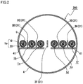
- a description will be given of a superconducting cable line 200 as shown in Fig. 2 in which six superconducting cables 1a to 1f having no superconducting shield layer are linearly arranged close to each other, and magnetic shield members 3D to 3H are each disposed between corresponding superconducting cables among superconducting cables 1a to 1f.
- the second embodiment is different from the first embodiment in only the manner in which superconducting cables 1a to 1f and magnetic shield members 3D to 3H are arranged, and is similar to the first embodiment in other features. The following description will be given chiefly of the difference.
- Superconducting cables 1a, 1b, 1c are arranged linearly on the same support platform 41, and superconducting cables 1d, 1e, 1f are arranged linearly on the same support platform 41.
- Magnetic shield members 3D to 3H are disposed respectively between adjacent superconducting cables 1a and 1b, between 1b and 1c, between 1c and 1d, between 1d and 1e, and 1e and 1f. Magnetic shield members 3D to 3H are not electromagnetically connected to support platform 41 but mechanically connected thereto thorough an electrically insulating member (not shown).
- magnetic shield members 3D to 3H are not electromagnetically connected to support platform 41 but are independent of each other, increase of the eddy current loss in magnetic shield members 3D to 3H can be suppressed, even when support platform 41 is made of a ferromagnetic material or electrically conductive material.
- superconducting cable line 200 includes a plurality of superconducting cables 1a to 1f having no superconducting shield layer and arranged linearly, the fact that magnetic shield members 3D to 3H are each disposed between corresponding superconducting cables among superconducting cables 1a to 1f enables reduction of the external magnetic field (vertical magnetic field) causing the eddy current loss in respective thermal insulation pipes 20 of superconducting cables 1a to 1f. Accordingly, generation of the eddy current loss due to the external magnetic field in thermal insulation pipes 20 of superconducting cables 1a to 1f can be suppressed. Since the eddy current loss generated particularly in inner pipe 21 included in thermal insulation pipe 20 and located on the side of the low temperature portion can be reduced, the load on the refrigerator can be reduced.
- a magnetic shield member can be provided to shield the thermal insulation pipe from the external magnetic field, and thereby reduce the eddy current loss and reduce the load on the refrigerator.
- This magnetic shield member is configured similarly to the magnetic shield member in the first embodiment.
- Superconducting cables of three phases each having no superconducting shield layer and each including a cable core housed in a thermal insulation pipe were disposed in a triangular arrangement, plate-shaped magnetic shield members were each disposed between corresponding superconducting cables, and a loss generated in the thermal insulation pipe and a loss generated in the magnetic shield member were exampled by the FEM analysis.
- An inner pipe of the thermal insulation pipe had an electrical conductivity of 2.02 MS/m and the outer pipe thereof had an electrical conductivity of 1.45 MS/m.
- the center-to-center distance between the cables of the phases was 350 mm.
- Conductor current of 12 kArms was applied to a superconducting conductor layer of the cable of each phase.
- the magnetic shield members are independent members which are not electromagnetically connected to each other but are independent of each other (see Fig. 1 ). Each magnetic shield member is disposed so that its one end is located at 25 mm from the center of the three phases. Each magnetic shield member is formed of a single ferromagnetic layer of 10 mm in thickness. The ferromagnetic layer is made of pure iron. Pure iron has an electrical conductivity of 10.44 MS/m.
- the magnetic shield members are independent members which are not electromagnetically connected to each other but are independent of each other (similarly to Test Example 1-1).
- Each magnetic shield member is formed of a single conductor layer of 10 mm in thickness.
- the conductor layer is made of aluminum.
- Aluminum has an electrical conductivity of 34.45 MS/m.
- the magnetic shield members are an integrated member in which the magnetic shield members are electromagnetically connected to each other. Respective ends of the magnetic shield members are electromagnetically connected together at the center of the three phases.
- Each magnetic shield member is formed of a ferromagnetic layer similar to that of Test Example 1-1.
- the magnetic shield members are an integrated member in which the magnetic shield members are electromagnetically connected to each other (similarly to Test Example 1-3).
- Each magnetic shield member is formed of a conductor layer similar to that of Test Example 1-2.
- the magnetic shield member is not disposed.
- the losses generated in the thermal insulation pipe (inner pipe and outer pipe) and the loss generated in the magnetic shield member are shown in Table 1.
- both the loss in the inner pipe and the loss in the outer pipe were reduced to be a half of the loss in Test Example 1-5 in which the magnetic shield member was not disposed.
- the loss of the inner pipe could be reduced to 3 W/m or less.
- the loss in the inner pipe was not less than 4 W/m and the reduction ratio is approximately 20%. Namely, it has been found that the shielding effect produced by the magnetic shield member is not sufficiently high in Test Example 1-2.
- the magnetic shield member is formed of a ferromagnetic layer and an external magnetic field (vertical magnetic field) is applied to the magnetic shield member, the orientation of the external magnetic field is changed and the magnetic field applied to the thermal insulation pipe is reduced.
- the magnetic shield member is formed of a conductor layer, even when an external magnetic field is applied to the magnetic shield member, the orientation of the external magnetic field remains the same and the external magnetic field is applied through the magnetic shield member to the thermal insulation pipe.
- the external-magnetic-field shielding effect is considered to be reduced for this reason.
- Test Example 1-3 while the loss in the inner pipe and the loss in the outer pipe were both reduced as compared with Test Example 5, the loss in the inner pipe exceeded 3 W/m.
- Test Example 1-4 While the loss in the inner pipe and the loss in the outer pipe were both reduced as compared with Test Example 1-5, the loss in the inner pipe exceeded 3 W/m. Namely, it has been found that, in Test Examples 1-3 and 1-4 in which the magnetic shield members are electromagnetically coupled together, the shielding effect produced by the magnetic shield member is not sufficiently high. In the case where the magnetic shield members are coupled together, the eddy current loss generated in each magnetic shield member is larger as compared with the case where the magnetic shield members are not coupled together. The shielding effect produced by the magnetic shield member is considered to be reduced for this reason.
- Table 1 shape material loss (W/m) inner pipe outer pipe magnetic shield member 1-1 coupled pure iron 2.9 3.8 3500 1-2 aluminum 4.4 5.8 227 1-3 not coupled pure iron 3.3 4.3 4162 1-4 aluminum 3.4 4.5 294 1-5 - - 5.6 7.1 -
- Test Example 2 the thickness of the magnetic shield member for the aforementioned Test Example 1-1 was used as a parameter, and the losses generated in the thermal insulation pipe and the loss generated in the magnetic shield member were examined by the FEM analysis (Test Examples 2-1 to 2-7; Test Example 2-7 is identical to the above-described Test Example 1-1).
- the magnetic shield member is formed of a single ferromagnetic layer. For each Test Example, the losses generated in the thermal insulation pipe and the loss generated in the magnetic shield member are shown in Table 2.
- the thickness of the magnetic shield member of 2 mm or more enables the loss in the inner pipe to be reduced to 3 W/m or less.
- the thickness of the magnetic shield member of 5 mm enables the loss in the inner pipe to be reduced to 2 W/m.
- a greater thickness of the magnetic shield member is accompanied by a greater loss in the magnetic shield member. A reason for this is considered as follows. A greater thickness of the magnetic shield member is accompanied by a greater volume thereof, and accordingly the eddy current loss generated in the magnetic shield member is increased. As the eddy current loss in the magnetic shield member increases, the shielding effect produced by the magnetic shield member decreases. For this reason, the loss in the inner pipe in Test Example 2-7 is considered to be larger than that in Test Example 2-6.
- the magnetic shield member with a thickness of 10 mm in Test Example 1-1 is a laminated body made up of a plurality of superposed ferromagnetic layers, the thickness of each ferromagnetic layer is used as a parameter, and the losses generated in the thermal insulation pipe and the loss generated in the magnetic shield member were examined by the FEM analysis (Text Examples 3-1 to 3-6; Test Example 3-1 is identical to Test Example 1-1). While an electrically insulating material is interposed between the ferromagnetic layers, the thickness of the electrically insulating material is not taken into consideration for Test Example 3. For each Test Example, the losses generated in the thermal insulation pipe and the loss generated in the magnetic shield member are shown in Table 3.
- Table 3 thickness (mm) loss (W/m) inner pipe outer pipe magnetic shield member 3-1 10.0 2.9 3.8 3500 3-2 5.0 1.8 2.3 1681 3-3 2.5 1.6 2.0 573 3-4 1.25 1.5 2.0 221 3-5 0.5 1.5 2.0 147 3-6 0.25 1.5 2.0 87
- the magnetic shield member is the laminated body made up of a plurality of ferromagnetic layers superposed with an electrically insulating material interposed in between, both the losses in the thermal insulation pipe and the loss in the magnetic shield member can be reduced.
- the magnetic shield member was a laminated body made up of ferromagnetic layers each having a thickness of 5.0 mm or less, the loss in the inner pipe could be reduced to 2 W/m or less.
- the thickness of each ferromagnetic layer was thinner, namely 1.25 mm or less, the loss in the inner pipe could further be reduced to 1.5 W/m. It has also been found that a smaller thickness of each ferromagnetic layer enables further reduction of the loss in the magnetic shield member.
- the loss in the magnetic shield member could be reduced to 600 W/m or less.
- the loss in the magnetic shield member could be reduced to 150 W/m or less.
- the loss in the magnetic shield member could be reduced to 100 W/m or less.
- a reason for this is considered as follows. A smaller thickness of each magnetic shield member is accompanied by a smaller volume thereof, and therefore the eddy current loss in the magnetic shield member can be reduced. The reduced eddy current loss in the magnetic shield member causes enhancement of the shielding effect produced by the magnetic shield member, and therefore the loss in the inner pipe can be reduced to 1.5 W/m.
- the magnetic shield member having a thickness of 5 mm is a laminated body made up of a plurality of superposed ferromagnetic layers, and the thickness of each ferromagnetic layer is used as a parameter to examine the losses generated in the thermal insulation pipe and the loss generated in the magnetic shield member by the FEM analysis (Test Examples 4-1 to 4-5).
- the conditions except for the thickness of the magnetic shield member in Test Example 4 are similar to those of Test Example 3. While an electrically insulating material is interposed between the ferromagnetic layers, the thickness of the electrically insulating material is not taken into consideration for Test Example 4.
- the losses generated in the thermal insulation pipe and the loss generated in the magnetic shield member are shown in Table 4.
- Table 4 thickness (mm) loss (W/m) inner pipe outer pipe magnetic shield member 4-1 5.0 2.0 2.7 2288 4-2 2.5 1.7 2.2 811 4-3 1.25 1.6 2.1 291 4-4 0.5 1.6 2.1 147 4-5 0.25 1.6 2.1 84
- the magnetic shield member is a laminated body made up of a plurality of ferromagnetic layers superposed with an electrically insulating material interposed in between, both the losses in the thermal insulation pipe and the loss in the magnetic shield member can be reduced. Namely, it has been found that, in order to reduce both the loss in the inner pipe and the loss in the magnetic shield member, it is effective to superpose thin ferromagnetic layers with an electrically insulating material interposed in between.
- the magnetic shield member having a thickness of 10 mm was a laminated body made up of a plurality of superposed ferromagnetic layers, each ferromagnetic layer was an electromagnetic steel sheet with the conditions shown in Table 5 (type (whether the orientation of the crystal axis is directional or non-directional), thickness, electrical conductivity, saturated flux density), and the losses generated in the thermal insulation pipe and the loss generated in the magnetic shield member were examined by the FEM analysis (Test Examples 5-1 to 5-10).
- the arrangement of the superconducting cables and the magnetic shield members and the conditions for energization were similar to those of Test Example 1-1.
- the losses generated in thermal insulation pipe and the loss generated in the magnetic shield member are shown together in Table 5.
- the magnetic shield member is a laminated body made up of a plurality of electromagnetic steel sheets superposed with an electrically insulating material interposed in between, the loss in the inner pipe can be reduced to 1.5 W/m or less and the loss in the magnetic shield member can be reduced to 100 W/m or less, particularly 50 W/m or less.
- Test Example 5 no difference is found depending on whether the orientation of the electromagnetic steel sheet is directional or non-directional.
- the thickness of each electromagnetic steel sheet it has been found that a smaller thickness tends to cause further reduction of the loss in the magnetic shield member.
- a smaller thickness of the electromagnetic steel sheet of 0.23 mm enables the loss in the magnetic shield member to be reduced to 20 W/m or less.
- each electromagnetic steel sheet As to the electrical conductivity of each electromagnetic steel sheet, it has been found that a lower electrical conductivity tends to cause further reduction of the loss in the magnetic shield member. In particular, a lower electrical conductivity of the electromagnetic steel sheet of 3 MS/m or less enables the loss in the magnetic shield member to be reduced to 50 W/m or less.
- the magnetic shield member having a thickness of 5 mm was a laminated body made up of a plurality of superposed ferromagnetic layers, each ferromagnetic layer was an electromagnetic steel sheet with the conditions similar to those of Test Example 5, and the losses generated in the thermal insulation pipe and the loss generated in the magnetic shield member were examined by the FEM analysis (Test Examples 6-1 to 6-10).
- the conditions except for the thickness of the magnetic shield member in Test Example 6 are similar to those of Test Example 5.
- the losses generated in the thermal insulation pipe and the loss generated in the magnetic shield member are shown together in Table 6.
- the magnetic shield member is a laminated body made up of a plurality of electromagnetic steel sheets superposed with an electrically insulating material interposed in between, the loss in the inner pipe can be reduced to 1.6 W/m or less, and the loss in the magnetic shield member can be reduced to 100 W/m or less, particularly 50 W/m or less. Namely, it has been found that, in order to reduce both the loss in the inner pipe and the loss in the magnetic shield member, it is effective to superpose electromagnetic steel sheets with an electrically insulating material interposed in between.
- the superconducting cable line of the present invention is suitably applicable to a power transmission line where there is a possibility that a magnetic field is externally applied to the superconducting cable.
Landscapes
- Containers, Films, And Cooling For Superconductive Devices (AREA)
- Superconductors And Manufacturing Methods Therefor (AREA)
- Shielding Devices Or Components To Electric Or Magnetic Fields (AREA)
Claims (8)
- Supraleitende Kabelleitung (100), umfassend:mehrere supraleitende Kabel (1a, 1b, 1c), wobei jedes der supraleitenden Kabel (1a, 1b, 1c) aufweist:eine Kabelseele (10) mit einer supraleitenden Leiterschicht (12) undein Wärmeisolierungsrohr (20), in dem sich die Kabelseele (10) befindet, und das ein inneres Rohr (21), das mit Kühlmittel (C) befüllt werden soll, und ein äußeres Rohr (22), das außerhalb des inneren Rohrs (21) angeordnet ist, aufweist, undmehrere magnetische Abschirmelemente (3A, 3B, 3C) in einer Plattenform, die zwischen einem benachbarten Paar der supraleitenden Kabel angeordnet sind, wobei jedes der supraleitenden Kabel (1a, 1b, 1c) dazu ausgelegt ist, ein externes Magnetfeld zu erzeugen, wobei ein Paar (3A, 3B) der magnetischen Abschirmelemente (3A, 3B, 3C) dazu ausgelegt ist, das supraleitende Kabel (1a), das zwischen dem Paar (3A, 3B) der magnetischen Abschirmelemente (3A, 3B, 3C) angeordnet ist, von dem Magnetfeld abzuschirmen,wobei jedes der magnetischen Abschirmelemente (3A, 3B, 3C) eine aus einem ferromagnetischen Material bestehende ferromagnetische Schicht (31) aufweist und die magnetischen Abschirmelemente elektromagnetisch voneinander unabhängig sind.
- Supraleitende Kabelleitung (100) nach Anspruch 1, wobei
die drei supraleitenden Kabel (1a, 1b, 1c) in einer dreieckigen Anordnung angeordnet sind, und
die magnetischen Abschirmelemente (3A, 3B, 3C) jeweils zwischen entsprechenden supraleitenden Kabeln (1a, 1b, 1c) von den drei supraleitenden Kabeln angeordnet sind. - Supraleitende Kabelleitung (100) nach Anspruch 1 oder 2, wobei die ferromagnetische Schicht (31) eine gesättigte magnetische Flussdichte von wenigstens 1 T aufweist.
- Supraleitende Kabelleitung (100) nach einem der Ansprüche 1 bis 3, wobei die ferromagnetische Schicht (31) eine elektrische Leitfähigkeit von höchstens 5 MS/m aufweist.
- Supraleitende Kabelleitung (100) nach einem der Ansprüche 1 bis 4, wobei jedes magnetische Abschirmelement (3A, 3B, 3C) eine Dicke von wenigstens 2 mm und höchsten 10 mm aufweist.
- Supraleitende Kabelleitung (100) nach einem der Ansprüche 1 bis 5, wobei jedes magnetische Abschirmelement (3A, 3B, 3C) ein laminiertes Gebilde ist, das aus mehreren der ferromagnetischen Schichten (31) besteht, die mit einem zwischen ihnen eingefügten elektrisch isolierenden Material überlagert sind.
- Supraleitende Kabelleitung (100) nach Anspruch 6, wobei die ferromagnetischen Schichten (31) jeweils eine Dicke von höchstens 0,5 mm aufweisen.
- Supraleitende Kabelleitung (100) nach einem der Ansprüche 1 bis 7, wobei die ferromagnetische Schicht (31) ein elektromagnetisches Stahlblech ist.
Applications Claiming Priority (3)
| Application Number | Priority Date | Filing Date | Title |
|---|---|---|---|
| JP2014044364 | 2014-03-06 | ||
| JP2014230242A JP6200402B2 (ja) | 2014-03-06 | 2014-11-12 | 超電導ケーブル線路、及び断熱管路 |
| PCT/JP2015/052277 WO2015133204A1 (ja) | 2014-03-06 | 2015-01-28 | 超電導ケーブル線路、及び断熱管路 |
Publications (3)
| Publication Number | Publication Date |
|---|---|
| EP3115997A1 EP3115997A1 (de) | 2017-01-11 |
| EP3115997A4 EP3115997A4 (de) | 2017-10-18 |
| EP3115997B1 true EP3115997B1 (de) | 2019-03-06 |
Family
ID=54055016
Family Applications (1)
| Application Number | Title | Priority Date | Filing Date |
|---|---|---|---|
| EP15758663.7A Active EP3115997B1 (de) | 2014-03-06 | 2015-01-28 | Supraleitende kabeltrasse |
Country Status (3)
| Country | Link |
|---|---|
| EP (1) | EP3115997B1 (de) |
| JP (1) | JP6200402B2 (de) |
| WO (1) | WO2015133204A1 (de) |
Families Citing this family (3)
| Publication number | Priority date | Publication date | Assignee | Title |
|---|---|---|---|---|
| JP2016110988A (ja) * | 2014-12-04 | 2016-06-20 | 住友電気工業株式会社 | 超電導ケーブル、及び超電導ケーブル用ケーブルコア |
| CN113319412A (zh) * | 2021-06-28 | 2021-08-31 | 中铁八局集团电务工程有限公司 | 电缆线路穿越预埋钢管的处理方法 |
| US20250191816A1 (en) * | 2023-12-11 | 2025-06-12 | Halliburton Energy Services, Inc. | Superconducting cables for electrical submersible pump motors |
Family Cites Families (6)
| Publication number | Priority date | Publication date | Assignee | Title |
|---|---|---|---|---|
| AU2003255060B2 (en) * | 2003-07-30 | 2009-10-22 | Prysmian Cavi E Sistemi Energia S.R.L. | Method for shielding the magnetic field generated by an electrical power transmission line and electrical power transmission line so shielded |
| DE502008002580D1 (de) * | 2008-12-15 | 2011-03-24 | Nexans | Anordnung mit einem supraleitfähigen Kabel |
| JP5240008B2 (ja) * | 2009-03-30 | 2013-07-17 | 住友電気工業株式会社 | 直流超電導ケーブル |
| JP5397994B2 (ja) * | 2009-06-19 | 2014-01-22 | 住友電気工業株式会社 | 超電導ケーブル |
| WO2013072124A1 (en) * | 2011-11-14 | 2013-05-23 | Nv Bekaert Sa | Steel wire for magnetic field absorption |
| JP2013140764A (ja) * | 2011-12-06 | 2013-07-18 | Sumitomo Electric Ind Ltd | 超電導ケーブル、超電導ケーブル線路、超電導ケーブルの布設方法、及び超電導ケーブル線路の運転方法 |
-
2014
- 2014-11-12 JP JP2014230242A patent/JP6200402B2/ja not_active Expired - Fee Related
-
2015
- 2015-01-28 WO PCT/JP2015/052277 patent/WO2015133204A1/ja not_active Ceased
- 2015-01-28 EP EP15758663.7A patent/EP3115997B1/de active Active
Non-Patent Citations (1)
| Title |
|---|
| None * |
Also Published As
| Publication number | Publication date |
|---|---|
| EP3115997A1 (de) | 2017-01-11 |
| WO2015133204A1 (ja) | 2015-09-11 |
| JP6200402B2 (ja) | 2017-09-20 |
| EP3115997A4 (de) | 2017-10-18 |
| JP2015181094A (ja) | 2015-10-15 |
Similar Documents
| Publication | Publication Date | Title |
|---|---|---|
| CN102549678B (zh) | 超导电缆及交流输电电缆 | |
| EP2858079B1 (de) | Kontaktloser leistungsübertragungstransformator | |
| EP3734618A1 (de) | Ladesystem für einen elektrischen energiespeicher | |
| US10290392B2 (en) | Electric cables having self-protective properties and immunity to magnetic interferences | |
| US9002423B2 (en) | Superconducting cable | |
| CN108878053B (zh) | 超导引线组件、低温系统、及将超导引线组件安装在低温系统的方法 | |
| EP3115997B1 (de) | Supraleitende kabeltrasse | |
| US9159473B2 (en) | Method of electrically conductively connecting two superconductive cables | |
| US8748747B2 (en) | Arrangement with at least one superconductive cable | |
| KR20100069602A (ko) | 초전도 케이블을 갖는 구조체 | |
| CN104347189A (zh) | 用于两个超导电缆的导电连接的方法 | |
| CN100585753C (zh) | 电力电缆线路 | |
| JP5443835B2 (ja) | 超電導ケーブル線路 | |
| JP5936130B2 (ja) | 超伝導ケーブルとバスバー | |
| CN103959050A (zh) | 超导电缆的临界电流测量方法 | |
| JP5252324B2 (ja) | 超電導送電システム | |
| JP6216302B2 (ja) | 断熱管絶縁ユニット、及び超電導ケーブル線路 | |
| WO2012099029A1 (ja) | 超電導線材の接続構造体およびその製造方法 | |
| JP2014192114A (ja) | 超電導ケーブル | |
| JP2015181095A (ja) | 超電導ケーブル線路、及び断熱管路 | |
| JP2015216735A (ja) | 超電導ケーブル、及び超電導ケーブル線路 | |
| WO2013072124A1 (en) | Steel wire for magnetic field absorption | |
| WO2022077567A1 (zh) | 三相同轴超导电缆通电导体冷却结构以及超导电缆通电导体 | |
| KR100744412B1 (ko) | 자기 차폐 도료가 코팅된 초전도 선재를 구비하는 초전도케이블 코아 및 이를 구비하는 초전도 케이블 | |
| Yuan et al. | Harmonic impedance of single-core armored cables |
Legal Events
| Date | Code | Title | Description |
|---|---|---|---|
| PUAI | Public reference made under article 153(3) epc to a published international application that has entered the european phase |
Free format text: ORIGINAL CODE: 0009012 |
|
| STAA | Information on the status of an ep patent application or granted ep patent |
Free format text: STATUS: REQUEST FOR EXAMINATION WAS MADE |
|
| 17P | Request for examination filed |
Effective date: 20161004 |
|
| AK | Designated contracting states |
Kind code of ref document: A1 Designated state(s): AL AT BE BG CH CY CZ DE DK EE ES FI FR GB GR HR HU IE IS IT LI LT LU LV MC MK MT NL NO PL PT RO RS SE SI SK SM TR |
|
| AX | Request for extension of the european patent |
Extension state: BA ME |
|
| DAX | Request for extension of the european patent (deleted) | ||
| A4 | Supplementary search report drawn up and despatched |
Effective date: 20170920 |
|
| RIC1 | Information provided on ipc code assigned before grant |
Ipc: H01L 39/04 20060101AFI20170914BHEP Ipc: H01L 39/14 20060101ALI20170914BHEP |
|
| REG | Reference to a national code |
Ref country code: DE Ref legal event code: R079 Ref document number: 602015025909 Country of ref document: DE Free format text: PREVIOUS MAIN CLASS: H01B0012140000 Ipc: H01B0012000000 |
|
| GRAP | Despatch of communication of intention to grant a patent |
Free format text: ORIGINAL CODE: EPIDOSNIGR1 |
|
| STAA | Information on the status of an ep patent application or granted ep patent |
Free format text: STATUS: GRANT OF PATENT IS INTENDED |
|
| RIC1 | Information provided on ipc code assigned before grant |
Ipc: H01L 39/14 20060101ALI20180824BHEP Ipc: H01L 39/04 20060101AFI20180824BHEP |
|
| RIC1 | Information provided on ipc code assigned before grant |
Ipc: H01B 12/00 20060101AFI20180906BHEP Ipc: H02G 15/34 20060101ALI20180906BHEP |
|
| INTG | Intention to grant announced |
Effective date: 20180925 |
|
| GRAS | Grant fee paid |
Free format text: ORIGINAL CODE: EPIDOSNIGR3 |
|
| GRAA | (expected) grant |
Free format text: ORIGINAL CODE: 0009210 |
|
| STAA | Information on the status of an ep patent application or granted ep patent |
Free format text: STATUS: THE PATENT HAS BEEN GRANTED |
|
| AK | Designated contracting states |
Kind code of ref document: B1 Designated state(s): AL AT BE BG CH CY CZ DE DK EE ES FI FR GB GR HR HU IE IS IT LI LT LU LV MC MK MT NL NO PL PT RO RS SE SI SK SM TR |
|
| REG | Reference to a national code |
Ref country code: GB Ref legal event code: FG4D |
|
| REG | Reference to a national code |
Ref country code: CH Ref legal event code: EP Ref country code: AT Ref legal event code: REF Ref document number: 1105650 Country of ref document: AT Kind code of ref document: T Effective date: 20190315 |
|
| REG | Reference to a national code |
Ref country code: DE Ref legal event code: R096 Ref document number: 602015025909 Country of ref document: DE |
|
| REG | Reference to a national code |
Ref country code: IE Ref legal event code: FG4D |
|
| REG | Reference to a national code |
Ref country code: NL Ref legal event code: MP Effective date: 20190306 |
|
| REG | Reference to a national code |
Ref country code: LT Ref legal event code: MG4D |
|
| PG25 | Lapsed in a contracting state [announced via postgrant information from national office to epo] |
Ref country code: SE Free format text: LAPSE BECAUSE OF FAILURE TO SUBMIT A TRANSLATION OF THE DESCRIPTION OR TO PAY THE FEE WITHIN THE PRESCRIBED TIME-LIMIT Effective date: 20190306 Ref country code: FI Free format text: LAPSE BECAUSE OF FAILURE TO SUBMIT A TRANSLATION OF THE DESCRIPTION OR TO PAY THE FEE WITHIN THE PRESCRIBED TIME-LIMIT Effective date: 20190306 Ref country code: NO Free format text: LAPSE BECAUSE OF FAILURE TO SUBMIT A TRANSLATION OF THE DESCRIPTION OR TO PAY THE FEE WITHIN THE PRESCRIBED TIME-LIMIT Effective date: 20190606 Ref country code: LT Free format text: LAPSE BECAUSE OF FAILURE TO SUBMIT A TRANSLATION OF THE DESCRIPTION OR TO PAY THE FEE WITHIN THE PRESCRIBED TIME-LIMIT Effective date: 20190306 |
|
| PG25 | Lapsed in a contracting state [announced via postgrant information from national office to epo] |
Ref country code: GR Free format text: LAPSE BECAUSE OF FAILURE TO SUBMIT A TRANSLATION OF THE DESCRIPTION OR TO PAY THE FEE WITHIN THE PRESCRIBED TIME-LIMIT Effective date: 20190607 Ref country code: HR Free format text: LAPSE BECAUSE OF FAILURE TO SUBMIT A TRANSLATION OF THE DESCRIPTION OR TO PAY THE FEE WITHIN THE PRESCRIBED TIME-LIMIT Effective date: 20190306 Ref country code: NL Free format text: LAPSE BECAUSE OF FAILURE TO SUBMIT A TRANSLATION OF THE DESCRIPTION OR TO PAY THE FEE WITHIN THE PRESCRIBED TIME-LIMIT Effective date: 20190306 Ref country code: LV Free format text: LAPSE BECAUSE OF FAILURE TO SUBMIT A TRANSLATION OF THE DESCRIPTION OR TO PAY THE FEE WITHIN THE PRESCRIBED TIME-LIMIT Effective date: 20190306 Ref country code: RS Free format text: LAPSE BECAUSE OF FAILURE TO SUBMIT A TRANSLATION OF THE DESCRIPTION OR TO PAY THE FEE WITHIN THE PRESCRIBED TIME-LIMIT Effective date: 20190306 Ref country code: BG Free format text: LAPSE BECAUSE OF FAILURE TO SUBMIT A TRANSLATION OF THE DESCRIPTION OR TO PAY THE FEE WITHIN THE PRESCRIBED TIME-LIMIT Effective date: 20190606 |
|
| REG | Reference to a national code |
Ref country code: AT Ref legal event code: MK05 Ref document number: 1105650 Country of ref document: AT Kind code of ref document: T Effective date: 20190306 |
|
| PG25 | Lapsed in a contracting state [announced via postgrant information from national office to epo] |
Ref country code: SK Free format text: LAPSE BECAUSE OF FAILURE TO SUBMIT A TRANSLATION OF THE DESCRIPTION OR TO PAY THE FEE WITHIN THE PRESCRIBED TIME-LIMIT Effective date: 20190306 Ref country code: RO Free format text: LAPSE BECAUSE OF FAILURE TO SUBMIT A TRANSLATION OF THE DESCRIPTION OR TO PAY THE FEE WITHIN THE PRESCRIBED TIME-LIMIT Effective date: 20190306 Ref country code: IT Free format text: LAPSE BECAUSE OF FAILURE TO SUBMIT A TRANSLATION OF THE DESCRIPTION OR TO PAY THE FEE WITHIN THE PRESCRIBED TIME-LIMIT Effective date: 20190306 Ref country code: CZ Free format text: LAPSE BECAUSE OF FAILURE TO SUBMIT A TRANSLATION OF THE DESCRIPTION OR TO PAY THE FEE WITHIN THE PRESCRIBED TIME-LIMIT Effective date: 20190306 Ref country code: EE Free format text: LAPSE BECAUSE OF FAILURE TO SUBMIT A TRANSLATION OF THE DESCRIPTION OR TO PAY THE FEE WITHIN THE PRESCRIBED TIME-LIMIT Effective date: 20190306 Ref country code: PT Free format text: LAPSE BECAUSE OF FAILURE TO SUBMIT A TRANSLATION OF THE DESCRIPTION OR TO PAY THE FEE WITHIN THE PRESCRIBED TIME-LIMIT Effective date: 20190706 Ref country code: AL Free format text: LAPSE BECAUSE OF FAILURE TO SUBMIT A TRANSLATION OF THE DESCRIPTION OR TO PAY THE FEE WITHIN THE PRESCRIBED TIME-LIMIT Effective date: 20190306 Ref country code: ES Free format text: LAPSE BECAUSE OF FAILURE TO SUBMIT A TRANSLATION OF THE DESCRIPTION OR TO PAY THE FEE WITHIN THE PRESCRIBED TIME-LIMIT Effective date: 20190306 |
|
| PG25 | Lapsed in a contracting state [announced via postgrant information from national office to epo] |
Ref country code: SM Free format text: LAPSE BECAUSE OF FAILURE TO SUBMIT A TRANSLATION OF THE DESCRIPTION OR TO PAY THE FEE WITHIN THE PRESCRIBED TIME-LIMIT Effective date: 20190306 Ref country code: PL Free format text: LAPSE BECAUSE OF FAILURE TO SUBMIT A TRANSLATION OF THE DESCRIPTION OR TO PAY THE FEE WITHIN THE PRESCRIBED TIME-LIMIT Effective date: 20190306 |
|
| REG | Reference to a national code |
Ref country code: DE Ref legal event code: R097 Ref document number: 602015025909 Country of ref document: DE |
|
| PG25 | Lapsed in a contracting state [announced via postgrant information from national office to epo] |
Ref country code: AT Free format text: LAPSE BECAUSE OF FAILURE TO SUBMIT A TRANSLATION OF THE DESCRIPTION OR TO PAY THE FEE WITHIN THE PRESCRIBED TIME-LIMIT Effective date: 20190306 Ref country code: IS Free format text: LAPSE BECAUSE OF FAILURE TO SUBMIT A TRANSLATION OF THE DESCRIPTION OR TO PAY THE FEE WITHIN THE PRESCRIBED TIME-LIMIT Effective date: 20190706 |
|
| PLBE | No opposition filed within time limit |
Free format text: ORIGINAL CODE: 0009261 |
|
| STAA | Information on the status of an ep patent application or granted ep patent |
Free format text: STATUS: NO OPPOSITION FILED WITHIN TIME LIMIT |
|
| PG25 | Lapsed in a contracting state [announced via postgrant information from national office to epo] |
Ref country code: DK Free format text: LAPSE BECAUSE OF FAILURE TO SUBMIT A TRANSLATION OF THE DESCRIPTION OR TO PAY THE FEE WITHIN THE PRESCRIBED TIME-LIMIT Effective date: 20190306 |
|
| 26N | No opposition filed |
Effective date: 20191209 |
|
| PG25 | Lapsed in a contracting state [announced via postgrant information from national office to epo] |
Ref country code: SI Free format text: LAPSE BECAUSE OF FAILURE TO SUBMIT A TRANSLATION OF THE DESCRIPTION OR TO PAY THE FEE WITHIN THE PRESCRIBED TIME-LIMIT Effective date: 20190306 |
|
| PG25 | Lapsed in a contracting state [announced via postgrant information from national office to epo] |
Ref country code: TR Free format text: LAPSE BECAUSE OF FAILURE TO SUBMIT A TRANSLATION OF THE DESCRIPTION OR TO PAY THE FEE WITHIN THE PRESCRIBED TIME-LIMIT Effective date: 20190306 |
|
| REG | Reference to a national code |
Ref country code: DE Ref legal event code: R119 Ref document number: 602015025909 Country of ref document: DE |
|
| PG25 | Lapsed in a contracting state [announced via postgrant information from national office to epo] |
Ref country code: MC Free format text: LAPSE BECAUSE OF FAILURE TO SUBMIT A TRANSLATION OF THE DESCRIPTION OR TO PAY THE FEE WITHIN THE PRESCRIBED TIME-LIMIT Effective date: 20190306 |
|
| REG | Reference to a national code |
Ref country code: CH Ref legal event code: PL |
|
| GBPC | Gb: european patent ceased through non-payment of renewal fee |
Effective date: 20200128 |
|
| REG | Reference to a national code |
Ref country code: BE Ref legal event code: MM Effective date: 20200131 |
|
| PG25 | Lapsed in a contracting state [announced via postgrant information from national office to epo] |
Ref country code: LU Free format text: LAPSE BECAUSE OF NON-PAYMENT OF DUE FEES Effective date: 20200128 Ref country code: DE Free format text: LAPSE BECAUSE OF NON-PAYMENT OF DUE FEES Effective date: 20200801 Ref country code: GB Free format text: LAPSE BECAUSE OF NON-PAYMENT OF DUE FEES Effective date: 20200128 Ref country code: FR Free format text: LAPSE BECAUSE OF NON-PAYMENT OF DUE FEES Effective date: 20200131 |
|
| PG25 | Lapsed in a contracting state [announced via postgrant information from national office to epo] |
Ref country code: BE Free format text: LAPSE BECAUSE OF NON-PAYMENT OF DUE FEES Effective date: 20200131 Ref country code: LI Free format text: LAPSE BECAUSE OF NON-PAYMENT OF DUE FEES Effective date: 20200131 Ref country code: CH Free format text: LAPSE BECAUSE OF NON-PAYMENT OF DUE FEES Effective date: 20200131 |
|
| PG25 | Lapsed in a contracting state [announced via postgrant information from national office to epo] |
Ref country code: IE Free format text: LAPSE BECAUSE OF NON-PAYMENT OF DUE FEES Effective date: 20200128 |
|
| PG25 | Lapsed in a contracting state [announced via postgrant information from national office to epo] |
Ref country code: MT Free format text: LAPSE BECAUSE OF FAILURE TO SUBMIT A TRANSLATION OF THE DESCRIPTION OR TO PAY THE FEE WITHIN THE PRESCRIBED TIME-LIMIT Effective date: 20190306 Ref country code: CY Free format text: LAPSE BECAUSE OF FAILURE TO SUBMIT A TRANSLATION OF THE DESCRIPTION OR TO PAY THE FEE WITHIN THE PRESCRIBED TIME-LIMIT Effective date: 20190306 |
|
| PG25 | Lapsed in a contracting state [announced via postgrant information from national office to epo] |
Ref country code: MK Free format text: LAPSE BECAUSE OF FAILURE TO SUBMIT A TRANSLATION OF THE DESCRIPTION OR TO PAY THE FEE WITHIN THE PRESCRIBED TIME-LIMIT Effective date: 20190306 |