EP3734618A1 - Ladesystem für einen elektrischen energiespeicher - Google Patents
Ladesystem für einen elektrischen energiespeicher Download PDFInfo
- Publication number
- EP3734618A1 EP3734618A1 EP20172344.2A EP20172344A EP3734618A1 EP 3734618 A1 EP3734618 A1 EP 3734618A1 EP 20172344 A EP20172344 A EP 20172344A EP 3734618 A1 EP3734618 A1 EP 3734618A1
- Authority
- EP
- European Patent Office
- Prior art keywords
- cooling
- cable
- charging
- conductor
- charging system
- Prior art date
- Legal status (The legal status is an assumption and is not a legal conclusion. Google has not performed a legal analysis and makes no representation as to the accuracy of the status listed.)
- Granted
Links
- 238000004146 energy storage Methods 0.000 title claims abstract description 20
- 239000004020 conductor Substances 0.000 claims abstract description 122
- 238000000034 method Methods 0.000 claims abstract description 9
- 238000001816 cooling Methods 0.000 claims description 96
- 239000012809 cooling fluid Substances 0.000 claims description 52
- 230000007704 transition Effects 0.000 claims description 30
- 230000005540 biological transmission Effects 0.000 claims description 10
- 239000010410 layer Substances 0.000 description 8
- 238000010276 construction Methods 0.000 description 7
- 230000006378 damage Effects 0.000 description 4
- 238000009413 insulation Methods 0.000 description 4
- 239000013307 optical fiber Substances 0.000 description 3
- 230000008054 signal transmission Effects 0.000 description 3
- 230000032258 transport Effects 0.000 description 3
- 208000027418 Wounds and injury Diseases 0.000 description 2
- 230000000712 assembly Effects 0.000 description 2
- 238000000429 assembly Methods 0.000 description 2
- 239000002826 coolant Substances 0.000 description 2
- 239000000110 cooling liquid Substances 0.000 description 2
- 208000014674 injury Diseases 0.000 description 2
- 238000009434 installation Methods 0.000 description 2
- 230000008569 process Effects 0.000 description 2
- 239000003507 refrigerant Substances 0.000 description 2
- 230000004075 alteration Effects 0.000 description 1
- 238000005452 bending Methods 0.000 description 1
- 230000009286 beneficial effect Effects 0.000 description 1
- 238000010292 electrical insulation Methods 0.000 description 1
- 239000000945 filler Substances 0.000 description 1
- 239000012530 fluid Substances 0.000 description 1
- 239000011888 foil Substances 0.000 description 1
- 239000012212 insulator Substances 0.000 description 1
- 239000002184 metal Substances 0.000 description 1
- 238000012986 modification Methods 0.000 description 1
- 230000004048 modification Effects 0.000 description 1
- 239000011241 protective layer Substances 0.000 description 1
- 238000006467 substitution reaction Methods 0.000 description 1
- 238000004804 winding Methods 0.000 description 1
Images


Classifications
-
- H—ELECTRICITY
- H01—ELECTRIC ELEMENTS
- H01B—CABLES; CONDUCTORS; INSULATORS; SELECTION OF MATERIALS FOR THEIR CONDUCTIVE, INSULATING OR DIELECTRIC PROPERTIES
- H01B9/00—Power cables
- H01B9/006—Constructional features relating to the conductors
-
- H—ELECTRICITY
- H01—ELECTRIC ELEMENTS
- H01R—ELECTRICALLY-CONDUCTIVE CONNECTIONS; STRUCTURAL ASSOCIATIONS OF A PLURALITY OF MUTUALLY-INSULATED ELECTRICAL CONNECTING ELEMENTS; COUPLING DEVICES; CURRENT COLLECTORS
- H01R9/00—Structural associations of a plurality of mutually-insulated electrical connecting elements, e.g. terminal strips or terminal blocks; Terminals or binding posts mounted upon a base or in a case; Bases therefor
- H01R9/11—End pieces for multiconductor cables supported by the cable and for facilitating connections to other conductive members, e.g. for liquid cooled welding cables
-
- B—PERFORMING OPERATIONS; TRANSPORTING
- B60—VEHICLES IN GENERAL
- B60L—PROPULSION OF ELECTRICALLY-PROPELLED VEHICLES; SUPPLYING ELECTRIC POWER FOR AUXILIARY EQUIPMENT OF ELECTRICALLY-PROPELLED VEHICLES; ELECTRODYNAMIC BRAKE SYSTEMS FOR VEHICLES IN GENERAL; MAGNETIC SUSPENSION OR LEVITATION FOR VEHICLES; MONITORING OPERATING VARIABLES OF ELECTRICALLY-PROPELLED VEHICLES; ELECTRIC SAFETY DEVICES FOR ELECTRICALLY-PROPELLED VEHICLES
- B60L53/00—Methods of charging batteries, specially adapted for electric vehicles; Charging stations or on-board charging equipment therefor; Exchange of energy storage elements in electric vehicles
- B60L53/10—Methods of charging batteries, specially adapted for electric vehicles; Charging stations or on-board charging equipment therefor; Exchange of energy storage elements in electric vehicles characterised by the energy transfer between the charging station and the vehicle
- B60L53/14—Conductive energy transfer
- B60L53/16—Connectors, e.g. plugs or sockets, specially adapted for charging electric vehicles
-
- B—PERFORMING OPERATIONS; TRANSPORTING
- B60—VEHICLES IN GENERAL
- B60L—PROPULSION OF ELECTRICALLY-PROPELLED VEHICLES; SUPPLYING ELECTRIC POWER FOR AUXILIARY EQUIPMENT OF ELECTRICALLY-PROPELLED VEHICLES; ELECTRODYNAMIC BRAKE SYSTEMS FOR VEHICLES IN GENERAL; MAGNETIC SUSPENSION OR LEVITATION FOR VEHICLES; MONITORING OPERATING VARIABLES OF ELECTRICALLY-PROPELLED VEHICLES; ELECTRIC SAFETY DEVICES FOR ELECTRICALLY-PROPELLED VEHICLES
- B60L53/00—Methods of charging batteries, specially adapted for electric vehicles; Charging stations or on-board charging equipment therefor; Exchange of energy storage elements in electric vehicles
- B60L53/10—Methods of charging batteries, specially adapted for electric vehicles; Charging stations or on-board charging equipment therefor; Exchange of energy storage elements in electric vehicles characterised by the energy transfer between the charging station and the vehicle
- B60L53/14—Conductive energy transfer
- B60L53/18—Cables specially adapted for charging electric vehicles
-
- B—PERFORMING OPERATIONS; TRANSPORTING
- B60—VEHICLES IN GENERAL
- B60L—PROPULSION OF ELECTRICALLY-PROPELLED VEHICLES; SUPPLYING ELECTRIC POWER FOR AUXILIARY EQUIPMENT OF ELECTRICALLY-PROPELLED VEHICLES; ELECTRODYNAMIC BRAKE SYSTEMS FOR VEHICLES IN GENERAL; MAGNETIC SUSPENSION OR LEVITATION FOR VEHICLES; MONITORING OPERATING VARIABLES OF ELECTRICALLY-PROPELLED VEHICLES; ELECTRIC SAFETY DEVICES FOR ELECTRICALLY-PROPELLED VEHICLES
- B60L53/00—Methods of charging batteries, specially adapted for electric vehicles; Charging stations or on-board charging equipment therefor; Exchange of energy storage elements in electric vehicles
- B60L53/30—Constructional details of charging stations
- B60L53/302—Cooling of charging equipment
-
- F—MECHANICAL ENGINEERING; LIGHTING; HEATING; WEAPONS; BLASTING
- F16—ENGINEERING ELEMENTS AND UNITS; GENERAL MEASURES FOR PRODUCING AND MAINTAINING EFFECTIVE FUNCTIONING OF MACHINES OR INSTALLATIONS; THERMAL INSULATION IN GENERAL
- F16L—PIPES; JOINTS OR FITTINGS FOR PIPES; SUPPORTS FOR PIPES, CABLES OR PROTECTIVE TUBING; MEANS FOR THERMAL INSULATION IN GENERAL
- F16L53/00—Heating of pipes or pipe systems; Cooling of pipes or pipe systems
- F16L53/70—Cooling of pipes or pipe systems
-
- H—ELECTRICITY
- H01—ELECTRIC ELEMENTS
- H01B—CABLES; CONDUCTORS; INSULATORS; SELECTION OF MATERIALS FOR THEIR CONDUCTIVE, INSULATING OR DIELECTRIC PROPERTIES
- H01B7/00—Insulated conductors or cables characterised by their form
- H01B7/42—Insulated conductors or cables characterised by their form with arrangements for heat dissipation or conduction
- H01B7/421—Insulated conductors or cables characterised by their form with arrangements for heat dissipation or conduction for heat dissipation
- H01B7/423—Insulated conductors or cables characterised by their form with arrangements for heat dissipation or conduction for heat dissipation using a cooling fluid
- H01B7/425—Insulated conductors or cables characterised by their form with arrangements for heat dissipation or conduction for heat dissipation using a cooling fluid the construction being bendable
-
- H—ELECTRICITY
- H02—GENERATION; CONVERSION OR DISTRIBUTION OF ELECTRIC POWER
- H02J—CIRCUIT ARRANGEMENTS OR SYSTEMS FOR SUPPLYING OR DISTRIBUTING ELECTRIC POWER; SYSTEMS FOR STORING ELECTRIC ENERGY
- H02J7/00—Circuit arrangements for charging or depolarising batteries or for supplying loads from batteries
- H02J7/0042—Circuit arrangements for charging or depolarising batteries or for supplying loads from batteries characterised by the mechanical construction
- H02J7/0045—Circuit arrangements for charging or depolarising batteries or for supplying loads from batteries characterised by the mechanical construction concerning the insertion or the connection of the batteries
-
- H—ELECTRICITY
- H01—ELECTRIC ELEMENTS
- H01B—CABLES; CONDUCTORS; INSULATORS; SELECTION OF MATERIALS FOR THEIR CONDUCTIVE, INSULATING OR DIELECTRIC PROPERTIES
- H01B9/00—Power cables
- H01B9/02—Power cables with screens or conductive layers, e.g. for avoiding large potential gradients
-
- Y—GENERAL TAGGING OF NEW TECHNOLOGICAL DEVELOPMENTS; GENERAL TAGGING OF CROSS-SECTIONAL TECHNOLOGIES SPANNING OVER SEVERAL SECTIONS OF THE IPC; TECHNICAL SUBJECTS COVERED BY FORMER USPC CROSS-REFERENCE ART COLLECTIONS [XRACs] AND DIGESTS
- Y02—TECHNOLOGIES OR APPLICATIONS FOR MITIGATION OR ADAPTATION AGAINST CLIMATE CHANGE
- Y02T—CLIMATE CHANGE MITIGATION TECHNOLOGIES RELATED TO TRANSPORTATION
- Y02T10/00—Road transport of goods or passengers
- Y02T10/60—Other road transportation technologies with climate change mitigation effect
- Y02T10/70—Energy storage systems for electromobility, e.g. batteries
-
- Y—GENERAL TAGGING OF NEW TECHNOLOGICAL DEVELOPMENTS; GENERAL TAGGING OF CROSS-SECTIONAL TECHNOLOGIES SPANNING OVER SEVERAL SECTIONS OF THE IPC; TECHNICAL SUBJECTS COVERED BY FORMER USPC CROSS-REFERENCE ART COLLECTIONS [XRACs] AND DIGESTS
- Y02—TECHNOLOGIES OR APPLICATIONS FOR MITIGATION OR ADAPTATION AGAINST CLIMATE CHANGE
- Y02T—CLIMATE CHANGE MITIGATION TECHNOLOGIES RELATED TO TRANSPORTATION
- Y02T10/00—Road transport of goods or passengers
- Y02T10/60—Other road transportation technologies with climate change mitigation effect
- Y02T10/7072—Electromobility specific charging systems or methods for batteries, ultracapacitors, supercapacitors or double-layer capacitors
-
- Y—GENERAL TAGGING OF NEW TECHNOLOGICAL DEVELOPMENTS; GENERAL TAGGING OF CROSS-SECTIONAL TECHNOLOGIES SPANNING OVER SEVERAL SECTIONS OF THE IPC; TECHNICAL SUBJECTS COVERED BY FORMER USPC CROSS-REFERENCE ART COLLECTIONS [XRACs] AND DIGESTS
- Y02—TECHNOLOGIES OR APPLICATIONS FOR MITIGATION OR ADAPTATION AGAINST CLIMATE CHANGE
- Y02T—CLIMATE CHANGE MITIGATION TECHNOLOGIES RELATED TO TRANSPORTATION
- Y02T90/00—Enabling technologies or technologies with a potential or indirect contribution to GHG emissions mitigation
- Y02T90/10—Technologies relating to charging of electric vehicles
- Y02T90/12—Electric charging stations
-
- Y—GENERAL TAGGING OF NEW TECHNOLOGICAL DEVELOPMENTS; GENERAL TAGGING OF CROSS-SECTIONAL TECHNOLOGIES SPANNING OVER SEVERAL SECTIONS OF THE IPC; TECHNICAL SUBJECTS COVERED BY FORMER USPC CROSS-REFERENCE ART COLLECTIONS [XRACs] AND DIGESTS
- Y02—TECHNOLOGIES OR APPLICATIONS FOR MITIGATION OR ADAPTATION AGAINST CLIMATE CHANGE
- Y02T—CLIMATE CHANGE MITIGATION TECHNOLOGIES RELATED TO TRANSPORTATION
- Y02T90/00—Enabling technologies or technologies with a potential or indirect contribution to GHG emissions mitigation
- Y02T90/10—Technologies relating to charging of electric vehicles
- Y02T90/14—Plug-in electric vehicles
Definitions
- the present invention relates to a charging system for an electric energy storage comprising a cable charging assembly, a plug transition between the charging cable assembly and the electric energy storage.
- a cable assembly comprises a cable provided with at least two separate power conductors and at least one earth conductor.
- the present invention also relates to a method for charging an electrical energy storage on basis of such a cable assembly.
- Cable assemblies as such are known.
- International application WO2018104234 relates to a high-current cable, in particular charging cable, comprising an outer sheath and a number of longitudinally extending transmission elements, each of these transmission elements having a core with a conductor and a core insulation and a first tube and wherein the core insulation and the first tube via a longitudinally extending connection connected to each other.
- WO2017133893 relates to a cable assembly comprising a cable hose and at least one conductor arranged therein, wherein the cable hose is spaced a distance apart from the conductor forming a first interstitial space between the at least conductor and the cable hose.
- a cable assembly comprises at least one tube for conveying of a cooling fluid for cooling of the cable assembly.
- the cable assembly comprises a connector comprising at least one contact member interconnected to the at least one conductor and a chamber wherein said chamber comprises a first port which is interconnected to the first interstitial space between the cable hose and the at least one conductor and a second port that is interconnected to the tube, such that cooling fluid may circulate from the tube, into the first interstitial space or vice versa.
- German Gebrauchsmusterschrift DE 20 2017 102368 relates to a charging cable for electric vehicles with at least one conductor designed to conduct a high current of about 100 Ampere, which has an electrical conductor and a surrounding electrical insulation, and with a cooling channel, wherein the electrical conductor is a wire conductor made from individual wires and the insulation is an insulating tube for forming the cooling channel over the entire length of the line, wherein the wire conductor is immediately surrounded by a free space through which a fluid-like coolant can be conducted.
- CN 109 036 694 relates to a cooling cable for a high-power charging connector, and includes a cable core and a protective layer wrapped around the cable core, the cable core is composed of two power wires, a ground wire, and a control wire wherein the gap between the cable cores is filled with a filler.
- the power wire includes a power conductor, a first cooling tube and an insulating layer, wherein the power conductor is wound around the first cooling tube, the insulating layer is wrapped on the power conductor.
- the grounding conductor includes a ground conductor, a second cooling tube and a shielding layer, wherein the ground conductor is wound on the second cooling tube, the shielding layer is wrapped around the ground wire conductor.
- CN 206711659 relates to an electric vehicle charging cable with a cooling tube, including a power wire core, a ground wire core, a backup power line, a control signal wire core, and a strap.
- the charging cable is provided with a number of cooling tubes, the power line core has a built-in cooling tube, and the conductor of the power line core is tightly wrapped on the cooling tube.
- the ground wire core is also provided with a cooling tube, wherein the conductor of the grounding core is tightly wrapped on the cooling tube and the control signal core surrounds another cooling tube.
- Such a charging cable is connected to a charging gun.
- CN206697276 relates to an electric vehicle high-current charging cable, comprising at least one wire, which is arranged in the cable, at least one first inflow pipe and one outflow pipe for transmitting cooling medium; the first inflow pipe passing through the wire, the first inflow tube is conductively connected to one end of the wire and one end of the outflow tube, and the outflow tube is arranged adjacent to the wire.
- Such an electric vehicle high-current charging cable further comprises an adapter, the adapter is provided with a through hole, and the first inflow pipe passes through the through hole and flows out.
- WO2018021401 relates to a power supply cable which is used for power supply to an automobile, comprising: a plurality of electric wires being twisted together, each of which includes a cooling pipe having flexibility, an electric conductor surrounding the cooling pipe, the electric conductor is configured by winding a plurality of conductor wires around the cooling pipe, and an insulator surrounding the electric conductor; and a sheath that covers the plurality of the electric wires, wherein half the number of the cooling pipes is used as an outward path of a refrigerant, and the remaining half the number of the cooling pipes is used as a return path of the refrigerant.
- High current cable cables are designed to transmit high amounts electrical power in short time. When transmitting high currents relatively large amounts of heat are generated and a corresponding high-current cable heats up relatively quickly during operation. For most installations, high current cables are designed such that at the maximum rating (i.e. the maximum current carrying capacity), the temperature of the cable does not exceed about 90°C to ensure that the insulation is not damaged. However in situations where people may come into contact with such cables the maximum temperature of the cable should be more limited to prevent injuries.
- a typical example of these cables are so-called charging cables for electric storage in e.g. vehicles through which relatively high currents are conducted during a charging process and which at the same time have to be designed in such a way that they can be touched during charging without injury and to allow repeated manipulation of the cable for connecting and disconnecting to a vehicle.
- a temperature rise in conductor and plug transitions may occur due to the high currents being transmitted. This temperature rise may be reduced by limiting the currents, but the charging process will take a longer time.
- the present invention therefore seeks to provide a high-current cable and a charging system for an electric energy storage.
- the present invention also seeks to provide a method for charging an electrical energy storage on basis of such a high-current cable assembly.
- the present invention thus relates to a charging system for an electric energy storage comprising a cable charging assembly, a plug transition between said charging cable assembly and said electric energy storage, said cable charging assembly comprising a cable provided with at least two separate power conductors and at least one earth conductor, wherein the at least two separate power conductors are spaced a distance apart from each other within said cable, each power conductor surrounds at least one tube, and each power conductor comprises a plurality of intertwisted wires stranded around said tube, wherein said cable charging assembly comprises at least two separate cooling circuits within said cable, namely a first cooling circuit comprising a cooling fluid in the tubes surrounded by the at least two power conductors and a second cooling circuit comprising a cooling fluid in auxiliary tubes to cool the plug transition.
- the first cooling circuit comprises a cooling unit.
- a temperature rise in the power conductor may occur due to the high currents being transmitted. This means that the cooling fluid or the cooling liquid in the first cooling circuit will take up the heat thus generated and that, due to the cooling circuit, the cooling fluid has to be cooled before it returns into the first cooling circuit.
- Such a cooling unit including measuring and control systems, will cool the cooling fluid to a predetermined temperature and the cooling fluid thus cooled will be returned into the first cooling circuit.
- the second cooling circuit comprises a cooling unit.
- a temperature rise in the plug transitions may occur due to the high currents being transmitted.
- the second cooling circuit transports a cooling fluid or a cooling liquid to the plug transitions and the cooling fluid will take up the heat thus generated in the plug transitions.
- a cooling unit including measuring and control systems, will cool the cooling fluid to a predetermined temperature and the cooling fluid thus cooled will be returned into the second cooling circuit.
- the first cooling circuit and the second cooling circuit comprise a mutual cooling unit.
- a mutual cooling unit controls and regulates the temperature of the cooling fluid of both the first cooling circuit and the second cooling circuit.
- the cooling fluids of both the first cooling circuit and the second cooling circuit are cooled in a mutual cooling unit including measuring and control systems.
- the cooling fluids that are returned are first mixed together and then the combined cooling fluid is cooled in a mutual cooling unit.
- the cooling fluid thus cooled is subsequently separated into a cooling fluid for the first cooling circuit and into a cooling fluid for the second cooling circuit.
- the at least one earth conductor surrounds said at least one auxiliary tube.
- Such a construction is beneficial for the dissipation of the heat generated by the plug transition.
- the cable is provided with two separate power conductors and two earth conductors, wherein the two separate power conductors each surround a tube for conveying of a cooling fluid and wherein the two earth conductors each surround an auxiliary tube for conveying of a cooling fluid.
- Such a construction allows for an efficient heat transfer between each of the two power conductors and the cooling fluid.
- the heated cooling fluid is transported through the tubes surrounded by the power conductors and can be transported back through the auxiliary tubes, or the auxiliary tubes are to be used for transporting a cooling fluid to and from a plug transition.
- each power conductor is surrounded by a sheath, said sheath being surrounded by an earth conductor.
- the at least two separate power conductors are surrounded by a common sheath, said common sheath being surrounded by an earth conductor.
- the cross sectional area of each power conductor is equal to or greater than the cross sectional area of each earth conductor.
- each earth conductor comprises a plurality of intertwisted wires. Such a construction allows for a repeated manipulation of the cable without damaging the cable.
- a tape wrapping is positioned between the tube for conveying of a cooling fluid and the power conductor.
- the tape wrapping adds an additional protection layer for the tube for conveying of a cooling fluid thereby minimizing the risk of damage to the tube for conveying of a cooling fluid when bending the final cable during practical use by the consumer.
- Such a tape wrapping may also be located at the outer circumference of the tube for conveying of a cooling fluid to cool the plug transition.
- a signal conductor is arranged within the cable in order to provide transmission of information along the cable.
- the present invention furthermore relates to a cable assembly as discussed before wherein one or more auxiliary tubes for conveying of a cooling fluid are provided at interstices between the at least two separate power conductors.
- the present invention furthermore relates to a charging system for an electric energy storage comprising a cable assembly as discussed before.
- the present charging system comprises a plug transition between the present charging cable assembly and the electric energy storage and comprises at least two separate cooling circuits, namely a first cooling circuit comprising a cooling fluid in the tubes surrounded by the at least two power conductors and a second cooling circuit comprising a cooling fluid to cool the plug transition.
- the present invention furthermore relates to a method for charging an electrical energy storage comprising: a base station, a charging cable assembly connected with the base station and a plug transition between the charging cable assembly and the electric energy storage, wherein the charging cable assembly is provided with at least two separate power conductors, at least one earth conductor and at least two auxiliary tubes, wherein each power conductor surrounds a tube, wherein a first cooling fluid is pumped from the base station through the tubes surrounded by the at least two separate power conductors and wherein a second cooling fluid is pumped from the base station through the auxiliary tubes for cooling the plug transitions.
- the charging current is at least 350 Amps, preferably at least 500 Amps, more preferably at least 1000 Amps.
- the diameter of the charging cable assembly is 45 mm or less.
- the cables and cable assemblies of the present invention can be used for any kind of electrical energy transport and allow to transport higher currents within the same cross sectional area of conductors, or cable diameter, when compared to conventional cables without cooling tubes.
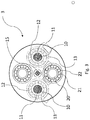
- Fig. 1 shows a first possible embodiment of a cable assembly 1 according to the invention.
- the cable assembly 1 comprises two separate power conductors and one earth conductor, wherein the two separate power conductors are spaced a distance apart from each other within the cable assembly.
- Cable assembly 1 comprises two tubes 10 that are arranged for conveying a cooling fluid along the cable assembly 1 and are arranged inside of cable assembly 1.
- Tube 10 has a wall 11.
- a power conductor 12 surrounds tube 10 for conveying of a cooling fluid.
- Each power conductor 12 comprises a plurality of intertwisted wires stranded around tube 10.
- the layer of wires is surrounded by a layer 13, e.g. a sheet or tube.
- cable assembly 1 may comprise a transmission element 15 suited for the transmission of signals and/or information.
- the transmission element may comprise two or more signal conductors and/or optical fibers.
- Cable 1 is also provided with an earth conductor 16.
- One or more auxiliary tubes may further be provided in the cable assembly of fig. 1 . Such auxiliary tubes may be used to covey a cooling fluid to and from plug transitions, or as return lines for cooling fluid supplied through the tubes 10 surrounded by the power conductors 12.
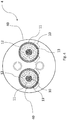
- Fig. 2 shows a second possible embodiment of a cable assembly 2 according to the invention.
- cable 2 further comprises an auxiliary tube 20 for conveying of a cooling fluid, wherein earth conductor 22 surrounds auxiliary tube 20.
- Auxiliary tube 20 has a wall 21.
- the cable assembly of this second possible embodiment may further optionally comprise one or more second auxiliary tubes that are not surrounded by a conductor.
- cable assembly 2 may comprise one or more transmission elements suited for the transmission of signals and/or information.
- the transmission element may comprise two or more signal conductors and/or optical fibers.
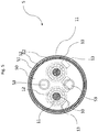
- Fig. 3 shows a third possible embodiment of a cable assembly 3 according to the invention.
- Cable 3 is provided with two separate power conductors and two earth conductors.
- Auxiliary tube 20 has a wall 21.
- each tube and each conductor (power or earth) may have equal cross sections.
- Such a construction allows for an easy installation and use of the cable assembly, because any connection of the two power and earth conductors will give a functioning system.
- the embodiment of Fig. 3 allows to use the cable system as a three phase cable in which case one of the earth conductors is used as a power conductor.
- the cable assembly of this third possible embodiment may further optionally comprise one or more second auxiliary tubes that are not surrounded by a conductor.
- Fig. 4 shows a fourth possible embodiment of a cable assembly 4 according to the invention.
- layer 13 is surrounded with an earth conductor 40.
- the cable assembly of this fourth possible embodiment may further optionally comprise one or more second auxiliary tubes that are not surrounded by a conductor.
- Fig. 5 shows a fifth possible embodiment of a cable assembly 5 according to the invention.
- the two separate power conductors are surrounded by and embedded in a common sheath 50, wherein the common sheath 50 is surrounded by an earth conductor 51 which is surrounded by an outer sheath.
- Auxiliary tubes 53 are located within cable assembly 5 and these tubes 53 are used for conveying of a cooling fluid.
- Fig. 6 schematically shows a cable for a charging cable assembly for charging an electrical energy storage in side view in section, i.e. a base station (not shown here), a charging cable assembly 6 connected with the base station and a connector assembly 60.
- Charging cable assembly 6 is provided with at least two separate power conductors 12, at least one earth conductor (not shown here) and at least two auxiliary tubes 53.
- Each power conductor 12 surrounds a tube 10, wherein a first cooling fluid is pumped from the base station through tubes 10 surrounded by separate power conductors 12 and wherein a second cooling fluid is pumped from the base station through auxiliary tubes 53 for cooling plug transitions 67.
- the connector assembly 60 surrounds an end of the charging cable assembly 6 and comprises a connector shelf, plug transitions 67, cooling blocks 66, conductor leads 68 and tube connector 69.
- Plug transitions 67 are surrounded by the connector shell 61 which includes one or more cooling blocks 66 in thermal conductive contact with the plug transitions 67.
- Auxiliary tubes 53 are connected to cooling blocks 66. The cooling fluid flowing through auxiliary tubes 53 into cooling blocks 66, i.e. the second cooling circuit, will take up the heat generated at the plug transition 67. The cooling fluid thus heated will be transported to a cooling unit 64 and returned, via a pump 65, to auxiliary tubes 53.
- Conductor leads 68 provide electrical connection between the power conductors 12 and plug transitions 67 and may consist of power conductors stripped and dismantled from the cable assembly end, or may be a separate part between each power conductor 12 and respective plug transition 67.
- Tube connector 69 provides a fluid connection between tubes 10 within the connector assembly.
- the first cooling circuit comprising tubes 10, tube connector 69, cooling unit 62 and pump 63 is used for cooling separate power conductors 12. Tubes 10 are surrounded by power conductors 12.
- the second cooling circuit comprising auxiliary tubes 53, cooling blocks 66, cooling unit 64 and pump 65 is used for cooling plug transition 67.
- auxiliary tubes 53 may be surrounded by an earth conductor.
- cooling units 62, 64 are shown but in a specific embodiment only one single cooling unit is used.
- Such a single cooling unit may include separate cooling circuits for cooling power conductors and plug transition, or such a mutual cooling unit may be used wherein the cooling fluids of the first cooling circuit and the second cooling circuit are cooled in such a mutual cooling unit.
- the embodiments shown in Figs. 2-6 may further comprise one or more transmission elements 15 suited for the transmission of signals and/or information.
- a transmission element 15 may comprise two or more signal conductors and/or optical fibers. (Not shown in Fig. 2 , 4 , 5 and 6 ).
- the earth conductors of the embodiments shown herein preferably comprise a plurality of intertwisted wires.
- the earth conductors may be provided as a braid or metal foil.
Landscapes
- Engineering & Computer Science (AREA)
- Power Engineering (AREA)
- Mechanical Engineering (AREA)
- Transportation (AREA)
- General Engineering & Computer Science (AREA)
- Insulated Conductors (AREA)
- Electric Propulsion And Braking For Vehicles (AREA)
- Charge And Discharge Circuits For Batteries Or The Like (AREA)
Applications Claiming Priority (1)
| Application Number | Priority Date | Filing Date | Title |
|---|---|---|---|
| NL2023045A NL2023045B1 (en) | 2019-05-01 | 2019-05-01 | Cable assembly |
Publications (3)
| Publication Number | Publication Date |
|---|---|
| EP3734618A1 true EP3734618A1 (de) | 2020-11-04 |
| EP3734618B1 EP3734618B1 (de) | 2023-08-23 |
| EP3734618C0 EP3734618C0 (de) | 2023-08-23 |
Family
ID=66476793
Family Applications (1)
| Application Number | Title | Priority Date | Filing Date |
|---|---|---|---|
| EP20172344.2A Active EP3734618B1 (de) | 2019-05-01 | 2020-04-30 | Ladesystem für einen elektrischen energiespeicher |
Country Status (6)
| Country | Link |
|---|---|
| US (1) | US11804315B2 (de) |
| EP (1) | EP3734618B1 (de) |
| CN (1) | CN111968782A (de) |
| CA (1) | CA3080220C (de) |
| ES (1) | ES2956239T3 (de) |
| NL (1) | NL2023045B1 (de) |
Cited By (5)
| Publication number | Priority date | Publication date | Assignee | Title |
|---|---|---|---|---|
| US20200350098A1 (en) * | 2019-05-01 | 2020-11-05 | Prysmian S.P.A. | Cable assembly |
| CN112735037A (zh) * | 2020-12-23 | 2021-04-30 | 尚廉智能科技(上海)有限公司 | 一种可共享充电的共享充电桩及服务器 |
| EP4125098A1 (de) * | 2021-07-30 | 2023-02-01 | Aptiv Technologies Limited | Stromkabelanordnung für ein stromverteilungssystem mit einem integrierten kühlsystem |
| FR3131067A1 (fr) * | 2021-12-20 | 2023-06-23 | Airbus Helicopters | Liaison électrique multicouche et ensemble de liaisons électriques multicouches avec deux interfaces et un circuit de refroidissement |
| EP4343793A1 (de) | 2022-09-21 | 2024-03-27 | Prysmian S.p.A. | Stromversorgungskabel, stromladekabelanordnung und system dafür |
Families Citing this family (2)
| Publication number | Priority date | Publication date | Assignee | Title |
|---|---|---|---|---|
| CN112700911B (zh) * | 2020-12-17 | 2022-04-12 | 河北嘉德电力器材有限公司 | 一种防水透气型防止误挖断的地下电缆 |
| CN113035438B (zh) * | 2021-03-12 | 2022-04-26 | 瑞安达电缆有限公司 | 一种新能源汽车充电用大功率充电电缆及使用方法 |
Citations (8)
| Publication number | Priority date | Publication date | Assignee | Title |
|---|---|---|---|---|
| DE202017102368U1 (de) | 2017-04-21 | 2017-05-10 | Hradil Spezialkabel Gmbh | Ladekabel für Elektrofahrzeuge |
| WO2017133893A1 (en) | 2016-02-01 | 2017-08-10 | Huber+Suhner Ag | Cable assembly |
| CN206697276U (zh) | 2016-12-20 | 2017-12-01 | 深圳宝兴电线电缆制造有限公司 | 一种电动汽车大电流充电电缆 |
| CN206711659U (zh) | 2017-04-12 | 2017-12-05 | 威海市泓淋电子有限公司 | 一种带冷却管的电动汽车充电线缆 |
| WO2018021401A1 (ja) | 2016-07-29 | 2018-02-01 | 株式会社フジクラ | 給電ケーブル、及びコネクタ付給電ケーブル |
| WO2018104234A1 (de) | 2016-12-05 | 2018-06-14 | Leoni Kabel Gmbh | Hochstromkabel und stromversorgungssystem mit hochstromkabel |
| WO2018139335A1 (ja) * | 2017-01-27 | 2018-08-02 | 株式会社フジクラ | 給電ケーブル、及びコネクタ付給電ケーブル |
| CN109036694A (zh) | 2018-07-31 | 2018-12-18 | 江苏大学 | 一种大功率充电连接器用冷却电缆 |
Family Cites Families (117)
| Publication number | Priority date | Publication date | Assignee | Title |
|---|---|---|---|---|
| US2870075A (en) * | 1945-03-03 | 1959-01-20 | Miles C Leverett | Nuclear reactor unloading apparatus |
| US3943965A (en) * | 1973-09-07 | 1976-03-16 | Matelena John J | Pipeline for transporting petroleum products through tundra |
| US4347433A (en) * | 1979-06-21 | 1982-08-31 | Eaton Corporation | Heat transfer apparatus for releasably securing heating or cooling means to pipe |
| DE3234476A1 (de) * | 1982-09-17 | 1984-04-05 | kabelmetal electro GmbH, 3000 Hannover | Rohrsystem fuer eine rohrleitung oder ein elektrisches kabel |
| EP0552737A1 (de) * | 1992-01-22 | 1993-07-28 | Hughes Aircraft Company | Wetterfester längsseitiger Lader |
| EP0982832A3 (de) * | 1996-08-07 | 2000-08-09 | Sumitomo Wiring Systems, Ltd. | Ladesystem für elektrisches Fahrzeug |
| JP2000133058A (ja) * | 1998-10-27 | 2000-05-12 | Toyota Autom Loom Works Ltd | 給電用ケーブル |
| SE0203249L (sv) * | 2002-11-05 | 2004-02-03 | Volvo Lastvagnar Ab | Kabelkanal för ett fordon samt metod för att montera ett kablage på ett fordon |
| US7358701B2 (en) * | 2003-02-07 | 2008-04-15 | Field Robert B | Method and system for modeling energy transfer |
| DE10322001B4 (de) * | 2003-05-16 | 2007-07-19 | Deutsches Zentrum für Luft- und Raumfahrt e.V. | Strahlungsmessvorrichtung |
| USD549645S1 (en) * | 2005-04-06 | 2007-08-28 | Prelec Sr Michael L | Battery charger casing |
| JP4715708B2 (ja) * | 2006-10-03 | 2011-07-06 | トヨタ自動車株式会社 | 電動車両および車両充電システム |
| ATE547614T1 (de) * | 2007-10-31 | 2012-03-15 | Behr Gmbh & Co Kg | Ansaugluft-einlassmodul, ansaugluft-einlasssystem,ansaugluft-einlasstrak , abgasrückführsystem, verbrennungsmotor |
| CN101978572B (zh) * | 2008-01-14 | 2013-06-19 | 威罗门飞行公司 | 滑动导体传输电缆 |
| JP5123144B2 (ja) * | 2008-11-21 | 2013-01-16 | 矢崎総業株式会社 | 充電用コネクタ |
| JP5536798B2 (ja) * | 2008-12-29 | 2014-07-02 | プリズミアン・ソチエタ・ペル・アツィオーニ | ケーブル外装移行部を有する海底送電ケーブル |
| BR122019014137B1 (pt) * | 2009-05-27 | 2020-03-03 | Prysmian S.P.A. | Sistemas de monitoramento de deformação para medir pelo menos a deformação por tração de pelo menos um cabo elétrico e de uma pluralidade de cabos elétricos |
| JP5340046B2 (ja) * | 2009-06-12 | 2013-11-13 | 富士重工業株式会社 | 充電装置および充電構造 |
| USD628960S1 (en) * | 2009-07-09 | 2010-12-14 | Nissan Jidosha Kabushiki Kaisha | Charger for automobile |
| EP2459605B1 (de) * | 2009-07-31 | 2013-06-12 | Prysmian S.p.A. | Mit einem niedrigtemperaturhärtenden harz gefüllte nieder- und mittelspannungs- kabelverbindung und kit für ihren einsatz |
| ES2456354T3 (es) * | 2009-08-05 | 2014-04-22 | Prysmian S.P.A. | Cable plano de energía |
| US8118147B2 (en) * | 2009-09-11 | 2012-02-21 | Better Place GmbH | Cable dispensing system |
| US7972167B2 (en) * | 2009-09-14 | 2011-07-05 | Better Place GmbH | Electrical connector with a flexible blade-shaped housing with a handle with an opening |
| BR112012005903A2 (pt) * | 2009-09-16 | 2018-03-20 | Prysmian Spa | método e sistema para monitorar a torção de um cabo |
| US9032809B2 (en) * | 2009-09-18 | 2015-05-19 | Prysmian S.P.A | Electric cable with bending sensor and monitoring system and method for detecting bending in at least one electric cable |
| IN2012DN02131A (de) * | 2009-09-28 | 2015-08-21 | Prysmian Spa | |
| US20110169447A1 (en) * | 2010-01-11 | 2011-07-14 | Leviton Manufacturing Co., Inc. | Electric vehicle supply equipment |
| ES2491097T3 (es) * | 2010-04-23 | 2014-09-05 | Prysmian S.P.A. | Blindaje de cables de alta tensión |
| AU2010364915B2 (en) * | 2010-11-29 | 2016-05-26 | Prysmian S.P.A. | Method for measuring the length of an electric cable that uses an optical fibre element as a sensor |
| JP5673798B2 (ja) * | 2011-03-24 | 2015-02-18 | トヨタ自動車株式会社 | コード収容装置および車両 |
| US9166428B2 (en) * | 2011-07-01 | 2015-10-20 | Toyota Jidosha Kabushiki Kaisha | Charging device |
| USD664088S1 (en) * | 2011-07-12 | 2012-07-24 | Coulomb Technologies, Inc. | Electric vehicle charging station having dual charging cable hangers and dual charging connector holsters |
| US9786961B2 (en) * | 2011-07-25 | 2017-10-10 | Lightening Energy | Rapid charging electric vehicle and method and apparatus for rapid charging |
| US8350526B2 (en) * | 2011-07-25 | 2013-01-08 | Lightening Energy | Station for rapidly charging an electric vehicle battery |
| US8174235B2 (en) * | 2011-07-25 | 2012-05-08 | Lightening Energy | System and method for recharging electric vehicle batteries |
| WO2013019336A1 (en) * | 2011-07-29 | 2013-02-07 | Lightening Energy | Electric battery rapid recharging system and method for military and other applications |
| EP3435389A1 (de) * | 2011-08-04 | 2019-01-30 | WiTricity Corporation | Abstimmbare drahtlosleistungsarchitekturen |
| US8974478B2 (en) * | 2011-09-20 | 2015-03-10 | Covidien Lp | Ultrasonic surgical system having a fluid cooled blade and related cooling methods therefor |
| JP5777990B2 (ja) * | 2011-09-21 | 2015-09-16 | 株式会社日立製作所 | 電気自動車用急速充電器及び急速充電システム |
| USD686982S1 (en) * | 2011-10-06 | 2013-07-30 | Control Module, Inc. | Overhead housing for electric vehicle service equipment |
| US9318257B2 (en) * | 2011-10-18 | 2016-04-19 | Witricity Corporation | Wireless energy transfer for packaging |
| JP2013099024A (ja) * | 2011-10-28 | 2013-05-20 | Mitsubishi Motors Corp | 電動車の充電方法および充電装置 |
| EP2684733A1 (de) * | 2012-07-11 | 2014-01-15 | Enzo Michele Illiano | Ladestation für ein Elektrofahrzeug und Ladegerät dafür |
| PL2883098T3 (pl) * | 2012-08-08 | 2021-11-15 | Prysmian S.P.A. | Niepalny światłowód dla instalacji poprzez wdmuchiwanie |
| KR20140129630A (ko) * | 2013-04-30 | 2014-11-07 | 신익호 | 배관 급속 결빙 모듈 |
| US9857821B2 (en) * | 2013-08-14 | 2018-01-02 | Witricity Corporation | Wireless power transfer frequency adjustment |
| US9586497B2 (en) * | 2013-08-22 | 2017-03-07 | Lightening Energy | Electric vehicle recharging station including a battery bank |
| WO2015055229A1 (en) * | 2013-10-15 | 2015-04-23 | Prysmian S.P.A. | High fibre count blown optical fibre unit and method of manufacturing |
| US9321362B2 (en) * | 2014-02-05 | 2016-04-26 | Tesia Motors, Inc. | Cooling of charging cable |
| CN104091631A (zh) * | 2014-07-01 | 2014-10-08 | 安徽天康股份有限公司 | 一种新型电动汽车螺旋式充电电缆 |
| US10857887B2 (en) * | 2014-10-03 | 2020-12-08 | Lightening Energy | Electric vehicle battery thermal management system and method |
| KR101718904B1 (ko) * | 2015-02-13 | 2017-03-23 | 한국과학기술원 | 극저온 액체 전송관 |
| KR102324346B1 (ko) * | 2015-04-29 | 2021-11-10 | 삼성에스디아이 주식회사 | 배터리 냉각 시스템 |
| DE102015112347A1 (de) * | 2015-07-29 | 2017-02-02 | Dr. Ing. H.C. F. Porsche Aktiengesellschaft | Ladestation mit einem Ladekabel |
| DE102015114133A1 (de) * | 2015-08-26 | 2017-03-02 | Phoenix Contact E-Mobility Gmbh | Stromkabel mit einer Kühlleitung |
| JP6554023B2 (ja) * | 2015-11-18 | 2019-07-31 | 昭和電線ケーブルシステム株式会社 | 内部冷却ケーブル |
| DE202015009531U1 (de) * | 2015-11-19 | 2018-02-27 | Dr. Ing. H.C. F. Porsche Aktiengesellschaft | Elektrisches Ladekabel für ein Kraftfahrzeug |
| DE102015120048A1 (de) * | 2015-11-19 | 2017-05-24 | Dr. Ing. H.C. F. Porsche Aktiengesellschaft | Elektrische Leitungsanordnung |
| DE102016105347A1 (de) * | 2016-03-22 | 2017-09-28 | Phoenix Contact E-Mobility Gmbh | Steckverbinderteil mit einem gekühlten Kontaktelement |
| DE102016206266A1 (de) * | 2016-04-14 | 2017-10-19 | Phoenix Contact E-Mobility Gmbh | Ladekabel zur Übertragung elektrischer Energie, Ladestecker und Ladestation zur Abgabe elektrischer Energie an einen Empfänger elektrischer Energie |
| DE102016107409A1 (de) * | 2016-04-21 | 2017-10-26 | Phoenix Contact E-Mobility Gmbh | Steckverbinderteil mit einem gekühlten Kontaktelement |
| JP6768340B2 (ja) * | 2016-04-28 | 2020-10-14 | 株式会社東芝 | 鉄道車両の電力変換装置 |
| US9873408B2 (en) * | 2016-05-11 | 2018-01-23 | Peter D. Capizzo | Device for refueling, exchanging, and charging power sources on remote controlled vehicles, UAVs, drones, or any type of robotic vehicle or machine with mobility |
| ES2858595T3 (es) * | 2016-05-20 | 2021-09-30 | Southwire Co Llc | Sistema de cable de carga refrigerado por líquido |
| BR112018074921B1 (pt) * | 2016-06-08 | 2021-03-16 | Prysmian S.P.A. | cabo de alimentação, e, método para prover um cabo de alimentação rastreável |
| EP3257700B1 (de) * | 2016-06-17 | 2019-10-30 | Sandvik Mining and Construction Oy | Ladesteckeranordnung mit sensor, in untertagefahrzeug |
| DE102016118191A1 (de) * | 2016-09-27 | 2018-03-29 | Phoenix Contact E-Mobility Gmbh | Ladesystem zum Aufladen eines Elektrofahrzeugs |
| US10222798B1 (en) * | 2016-09-29 | 2019-03-05 | Amazon Technologies, Inc. | Autonomous ground vehicles congregating in meeting areas |
| US10867723B2 (en) * | 2016-09-30 | 2020-12-15 | Faraday & Future Inc. | Liquid-cooled tangle resistant charge cable |
| CN106347166B (zh) * | 2016-11-22 | 2018-09-18 | 飞洲集团有限公司 | 一种电动车辆的整体冷却充电装置 |
| CN206282636U (zh) * | 2016-11-28 | 2017-06-27 | 深圳市沃尔核材股份有限公司 | 一种电缆和导线 |
| DE102016224106A1 (de) * | 2016-12-05 | 2018-06-07 | Leoni Kabel Gmbh | Hochstromkabel und Stromversorgungssystem mit Hochstromkabel |
| CN106782835B (zh) * | 2016-12-20 | 2019-07-16 | 深圳宝兴电线电缆制造有限公司 | 电动汽车大电流充电电缆 |
| JP6201071B1 (ja) * | 2017-02-07 | 2017-09-20 | 株式会社フジクラ | 給電ケーブル、及びコネクタ付き給電ケーブル |
| KR20180096259A (ko) * | 2017-02-21 | 2018-08-29 | 엘에스전선 주식회사 | 전기차 충전용 케이블 |
| DE102017104730A1 (de) * | 2017-03-07 | 2018-09-13 | Dr. Ing. H.C. F. Porsche Aktiengesellschaft | Ladestation |
| CN206532637U (zh) * | 2017-03-15 | 2017-09-29 | 深圳讯道实业股份有限公司 | 一种太阳能充电桩用耐高温电缆 |
| DE102017108174A1 (de) * | 2017-03-17 | 2018-09-20 | HARTING Automotive GmbH | Autoladesteckverbinder |
| WO2018200552A1 (en) * | 2017-04-24 | 2018-11-01 | Chargepoint, Inc. | Liquid cooled charging cable for charging electric vehicles |
| CN206741986U (zh) * | 2017-04-28 | 2017-12-12 | 深圳宝兴电线电缆制造有限公司 | 电动汽车冷却充电电缆 |
| CN207097480U (zh) * | 2017-04-28 | 2018-03-13 | 深圳宝兴电线电缆制造有限公司 | 电动汽车直流充电扁电缆 |
| US10180120B2 (en) * | 2017-05-05 | 2019-01-15 | Ford Global Technologies, Llc | Systems and methods for calibrating vehicle sensing devices |
| EP3401955B1 (de) * | 2017-05-12 | 2021-06-30 | ODU GmbH & Co. KG | Steckverbinder mit einem kühlmantel |
| CN206864231U (zh) * | 2017-05-24 | 2018-01-09 | 深圳宝兴电线电缆制造有限公司 | 一种电动汽车冷却充电电缆 |
| DE102017213938A1 (de) * | 2017-08-10 | 2018-10-11 | Bayerische Motoren Werke Aktiengesellschaft | Elektrische Speichervorrichtung zum Bereitstellen von elektrischer Energie für einen Ladevorgang zumindest eines elektrisch antreibbaren Kraftfahrzeugs sowie Nachrüstmodul und Betriebsverfahren |
| FR3070557A1 (fr) * | 2017-08-29 | 2019-03-01 | Valeo Systemes Thermiques | Dispositif de connexion electrique pour vehicule automobile refroidi par un circuit de fluide refrigerant |
| WO2019075151A1 (en) * | 2017-10-11 | 2019-04-18 | Mccoll Stuart Frazer | MAGNETIC SECURITY LOAD DEVICES |
| DE102017124028A1 (de) * | 2017-10-16 | 2019-04-18 | Phoenix Contact E-Mobility Gmbh | Kabelbaugruppe mit einer Kühlleitung und Zugentlastung |
| DE102018125835A1 (de) * | 2017-10-20 | 2019-04-25 | Phoenix Contact E-Mobility Gmbh | Kabelbaugruppe mit einer Kühlleitung und einer Zugentlastungsbaugruppe |
| CN107731396A (zh) * | 2017-10-24 | 2018-02-23 | 合肥邦立电子股份有限公司 | 一种耐用型新能源汽车充电电缆 |
| CN207441310U (zh) * | 2017-10-24 | 2018-06-01 | 合肥邦立电子股份有限公司 | 一种耐用型新能源汽车充电电缆 |
| US10618418B2 (en) * | 2017-12-28 | 2020-04-14 | Ford Global Technologies, Llc | Vehicle charging systems incorporating phase change materials for absorbing heat during charging events |
| DE102018100732A1 (de) * | 2018-01-15 | 2019-07-18 | Dr. Ing. H.C. F. Porsche Aktiengesellschaft | Schnellladestation mit Ladekabel und Temperiervorrichtung für das Ladekabel |
| DE102018100827A1 (de) * | 2018-01-16 | 2019-07-18 | Dr. Ing. H.C. F. Porsche Aktiengesellschaft | Ladekabel und Ladestation für Elektroautos |
| CN208014413U (zh) * | 2018-01-30 | 2018-10-26 | 广州南洋电缆有限公司 | 一种新能源汽车充电用电缆 |
| DE102018102207A1 (de) * | 2018-02-01 | 2019-08-01 | Dr. Ing. H.C. F. Porsche Aktiengesellschaft | Kraftfahrzeugladekabel |
| CN208093197U (zh) * | 2018-02-09 | 2018-11-13 | 江苏艾立可电子科技有限公司 | 一种新能源电动汽车充电桩扁电缆 |
| CN108306135A (zh) * | 2018-03-26 | 2018-07-20 | 洛阳正奇机械有限公司 | 一种大功率充电桩专用液冷电缆的软体导线电性连接结构 |
| CN109768405B (zh) * | 2019-02-11 | 2023-09-22 | 洛阳正奇机械有限公司 | 一种大功率充电桩用液冷电缆电极的冷却液双通道结构 |
| JP2019187141A (ja) * | 2018-04-12 | 2019-10-24 | トヨタ自動車株式会社 | 車両用バッテリの充電装置 |
| US10714236B2 (en) * | 2018-06-13 | 2020-07-14 | Te Connectivity Corporation | Charging system with cooling tube |
| CN108878014A (zh) * | 2018-07-27 | 2018-11-23 | 中天科技装备电缆有限公司 | 一种冷却型耐高温直流充电电缆 |
| CN108922658A (zh) * | 2018-08-03 | 2018-11-30 | 威海市泓淋电力技术股份有限公司 | 一种带冷却功能的大功率充电枪用电缆 |
| CN208589277U (zh) * | 2018-08-03 | 2019-03-08 | 威海市泓淋电力技术股份有限公司 | 一种带冷却功能的大功率充电枪用电缆 |
| CN109215872A (zh) * | 2018-09-06 | 2019-01-15 | 宁波聚亿新能源科技有限公司 | 一种液冷线缆及使用其的电动车充电缆线冷却装置 |
| CN208753040U (zh) * | 2018-09-06 | 2019-04-16 | 宁波聚亿新能源科技有限公司 | 一种液冷线缆及使用其的电动车充电缆线冷却装置 |
| DE102018122680B3 (de) * | 2018-09-17 | 2020-02-20 | Dr. Ing. H.C. F. Porsche Aktiengesellschaft | Kraftfahrzeugladekabel |
| CN109215873A (zh) * | 2018-09-25 | 2019-01-15 | 山东大学 | 液体冷却充电电缆及电动汽车快速充电设备 |
| CN110010286A (zh) * | 2019-02-25 | 2019-07-12 | 顺科新能源技术股份有限公司 | 一种固定式电动车充电桩冷却系统 |
| NL2023045B1 (en) * | 2019-05-01 | 2020-12-02 | Prysmian Spa | Cable assembly |
| CN110120566A (zh) * | 2019-05-07 | 2019-08-13 | 奇瑞新能源汽车技术有限公司 | 一种电动汽车动力电池冷却系统及电动汽车 |
| DE102019112843B3 (de) * | 2019-05-16 | 2020-09-03 | Dr. Ing. H.C. F. Porsche Aktiengesellschaft | Kraftfahrzeugladekabel |
| CN209962721U (zh) * | 2019-07-08 | 2020-01-17 | 江苏宝建特种电缆有限公司 | 一种汽车充电用电缆 |
| CN210805262U (zh) * | 2019-07-23 | 2020-06-19 | 上海起帆电缆股份有限公司 | 一种高载流快速充电用电缆 |
| WO2021045560A1 (ko) * | 2019-09-05 | 2021-03-11 | 엘에스전선 주식회사 | 전기차 충전용 케이블 |
| WO2021091216A1 (ko) * | 2019-11-06 | 2021-05-14 | 엘에스전선 주식회사 | 전기차 충전용 케이블 어셈블리 |
| KR20200074931A (ko) * | 2020-06-17 | 2020-06-25 | 엘에스전선 주식회사 | 전기차 충전용 케이블 |
-
2019
- 2019-05-01 NL NL2023045A patent/NL2023045B1/en active
-
2020
- 2020-04-30 EP EP20172344.2A patent/EP3734618B1/de active Active
- 2020-04-30 ES ES20172344T patent/ES2956239T3/es active Active
- 2020-04-30 CA CA3080220A patent/CA3080220C/en active Active
- 2020-05-01 US US16/864,295 patent/US11804315B2/en active Active
- 2020-05-06 CN CN202010372923.5A patent/CN111968782A/zh active Pending
Patent Citations (10)
| Publication number | Priority date | Publication date | Assignee | Title |
|---|---|---|---|---|
| WO2017133893A1 (en) | 2016-02-01 | 2017-08-10 | Huber+Suhner Ag | Cable assembly |
| WO2018021401A1 (ja) | 2016-07-29 | 2018-02-01 | 株式会社フジクラ | 給電ケーブル、及びコネクタ付給電ケーブル |
| EP3493224A1 (de) * | 2016-07-29 | 2019-06-05 | Fujikura Ltd. | Stromversorgungskabel und mit verbinder ausgestattetes stromversorgungskabel |
| WO2018104234A1 (de) | 2016-12-05 | 2018-06-14 | Leoni Kabel Gmbh | Hochstromkabel und stromversorgungssystem mit hochstromkabel |
| CN206697276U (zh) | 2016-12-20 | 2017-12-01 | 深圳宝兴电线电缆制造有限公司 | 一种电动汽车大电流充电电缆 |
| WO2018139335A1 (ja) * | 2017-01-27 | 2018-08-02 | 株式会社フジクラ | 給電ケーブル、及びコネクタ付給電ケーブル |
| EP3576105A1 (de) * | 2017-01-27 | 2019-12-04 | Fujikura Ltd. | Stromversorgungskabel und stromversorgungskabel mit dem verbinder |
| CN206711659U (zh) | 2017-04-12 | 2017-12-05 | 威海市泓淋电子有限公司 | 一种带冷却管的电动汽车充电线缆 |
| DE202017102368U1 (de) | 2017-04-21 | 2017-05-10 | Hradil Spezialkabel Gmbh | Ladekabel für Elektrofahrzeuge |
| CN109036694A (zh) | 2018-07-31 | 2018-12-18 | 江苏大学 | 一种大功率充电连接器用冷却电缆 |
Cited By (7)
| Publication number | Priority date | Publication date | Assignee | Title |
|---|---|---|---|---|
| US20200350098A1 (en) * | 2019-05-01 | 2020-11-05 | Prysmian S.P.A. | Cable assembly |
| US11804315B2 (en) * | 2019-05-01 | 2023-10-31 | Prysmian S.P.A. | EV charging cable system with cooling |
| CN112735037A (zh) * | 2020-12-23 | 2021-04-30 | 尚廉智能科技(上海)有限公司 | 一种可共享充电的共享充电桩及服务器 |
| EP4125098A1 (de) * | 2021-07-30 | 2023-02-01 | Aptiv Technologies Limited | Stromkabelanordnung für ein stromverteilungssystem mit einem integrierten kühlsystem |
| US11935672B2 (en) | 2021-07-30 | 2024-03-19 | Aptiv Technologies AG | Power cable assembly for a power distribution system having an integrated cooling system |
| FR3131067A1 (fr) * | 2021-12-20 | 2023-06-23 | Airbus Helicopters | Liaison électrique multicouche et ensemble de liaisons électriques multicouches avec deux interfaces et un circuit de refroidissement |
| EP4343793A1 (de) | 2022-09-21 | 2024-03-27 | Prysmian S.p.A. | Stromversorgungskabel, stromladekabelanordnung und system dafür |
Also Published As
| Publication number | Publication date |
|---|---|
| CA3080220C (en) | 2023-11-28 |
| CA3080220A1 (en) | 2020-11-01 |
| CN111968782A (zh) | 2020-11-20 |
| ES2956239T3 (es) | 2023-12-15 |
| EP3734618B1 (de) | 2023-08-23 |
| US11804315B2 (en) | 2023-10-31 |
| EP3734618C0 (de) | 2023-08-23 |
| NL2023045A (en) | 2020-11-18 |
| NL2023045B1 (en) | 2020-12-02 |
| US20200350098A1 (en) | 2020-11-05 |
Similar Documents
| Publication | Publication Date | Title |
|---|---|---|
| EP3734618A1 (de) | Ladesystem für einen elektrischen energiespeicher | |
| JP3226493U (ja) | 出力端子タブと、第1出力端子管および第2出力端子管と、流体路とを備えた装置 | |
| JP5674961B2 (ja) | 高圧電気ケーブル | |
| EP3770925B1 (de) | Starkstromladekabel zum laden eines elektrischen fahrzeugs | |
| CN114097045A (zh) | 用于为电动车辆充电的强电流充电电缆 | |
| JP6554023B2 (ja) | 内部冷却ケーブル | |
| US3013101A (en) | High-power, high-voltage electric cable installation | |
| EP3780034B1 (de) | Flüssigkeitsfreier eingetauchter transformator | |
| EP3349542B1 (de) | Induktionsheizkabel mit steuerleitern | |
| WO2023178350A1 (en) | Lower loss charging cable |
Legal Events
| Date | Code | Title | Description |
|---|---|---|---|
| PUAI | Public reference made under article 153(3) epc to a published international application that has entered the european phase |
Free format text: ORIGINAL CODE: 0009012 |
|
| STAA | Information on the status of an ep patent application or granted ep patent |
Free format text: STATUS: THE APPLICATION HAS BEEN PUBLISHED |
|
| AK | Designated contracting states |
Kind code of ref document: A1 Designated state(s): AL AT BE BG CH CY CZ DE DK EE ES FI FR GB GR HR HU IE IS IT LI LT LU LV MC MK MT NL NO PL PT RO RS SE SI SK SM TR |
|
| AX | Request for extension of the european patent |
Extension state: BA ME |
|
| STAA | Information on the status of an ep patent application or granted ep patent |
Free format text: STATUS: REQUEST FOR EXAMINATION WAS MADE |
|
| 17P | Request for examination filed |
Effective date: 20210503 |
|
| RBV | Designated contracting states (corrected) |
Designated state(s): AL AT BE BG CH CY CZ DE DK EE ES FI FR GB GR HR HU IE IS IT LI LT LU LV MC MK MT NL NO PL PT RO RS SE SI SK SM TR |
|
| STAA | Information on the status of an ep patent application or granted ep patent |
Free format text: STATUS: EXAMINATION IS IN PROGRESS |
|
| 17Q | First examination report despatched |
Effective date: 20210802 |
|
| GRAP | Despatch of communication of intention to grant a patent |
Free format text: ORIGINAL CODE: EPIDOSNIGR1 |
|
| STAA | Information on the status of an ep patent application or granted ep patent |
Free format text: STATUS: GRANT OF PATENT IS INTENDED |
|
| INTG | Intention to grant announced |
Effective date: 20230329 |
|
| GRAJ | Information related to disapproval of communication of intention to grant by the applicant or resumption of examination proceedings by the epo deleted |
Free format text: ORIGINAL CODE: EPIDOSDIGR1 |
|
| STAA | Information on the status of an ep patent application or granted ep patent |
Free format text: STATUS: EXAMINATION IS IN PROGRESS |
|
| GRAP | Despatch of communication of intention to grant a patent |
Free format text: ORIGINAL CODE: EPIDOSNIGR1 |
|
| STAA | Information on the status of an ep patent application or granted ep patent |
Free format text: STATUS: GRANT OF PATENT IS INTENDED |
|
| INTC | Intention to grant announced (deleted) | ||
| GRAS | Grant fee paid |
Free format text: ORIGINAL CODE: EPIDOSNIGR3 |
|
| INTG | Intention to grant announced |
Effective date: 20230623 |
|
| GRAA | (expected) grant |
Free format text: ORIGINAL CODE: 0009210 |
|
| STAA | Information on the status of an ep patent application or granted ep patent |
Free format text: STATUS: THE PATENT HAS BEEN GRANTED |
|
| AK | Designated contracting states |
Kind code of ref document: B1 Designated state(s): AL AT BE BG CH CY CZ DE DK EE ES FI FR GB GR HR HU IE IS IT LI LT LU LV MC MK MT NL NO PL PT RO RS SE SI SK SM TR |
|
| REG | Reference to a national code |
Ref country code: GB Ref legal event code: FG4D |
|
| REG | Reference to a national code |
Ref country code: CH Ref legal event code: EP |
|
| REG | Reference to a national code |
Ref country code: IE Ref legal event code: FG4D |
|
| REG | Reference to a national code |
Ref country code: DE Ref legal event code: R096 Ref document number: 602020016060 Country of ref document: DE |
|
| U01 | Request for unitary effect filed |
Effective date: 20230919 |
|
| U07 | Unitary effect registered |
Designated state(s): AT BE BG DE DK EE FI FR IT LT LU LV MT NL PT SE SI Effective date: 20230925 |
|
| REG | Reference to a national code |
Ref country code: ES Ref legal event code: FG2A Ref document number: 2956239 Country of ref document: ES Kind code of ref document: T3 Effective date: 20231215 |
|
| PG25 | Lapsed in a contracting state [announced via postgrant information from national office to epo] |
Ref country code: GR Free format text: LAPSE BECAUSE OF FAILURE TO SUBMIT A TRANSLATION OF THE DESCRIPTION OR TO PAY THE FEE WITHIN THE PRESCRIBED TIME-LIMIT Effective date: 20231124 |
|
| PG25 | Lapsed in a contracting state [announced via postgrant information from national office to epo] |
Ref country code: IS Free format text: LAPSE BECAUSE OF FAILURE TO SUBMIT A TRANSLATION OF THE DESCRIPTION OR TO PAY THE FEE WITHIN THE PRESCRIBED TIME-LIMIT Effective date: 20231223 |
|
| PG25 | Lapsed in a contracting state [announced via postgrant information from national office to epo] |
Ref country code: RS Free format text: LAPSE BECAUSE OF FAILURE TO SUBMIT A TRANSLATION OF THE DESCRIPTION OR TO PAY THE FEE WITHIN THE PRESCRIBED TIME-LIMIT Effective date: 20230823 Ref country code: NO Free format text: LAPSE BECAUSE OF FAILURE TO SUBMIT A TRANSLATION OF THE DESCRIPTION OR TO PAY THE FEE WITHIN THE PRESCRIBED TIME-LIMIT Effective date: 20231123 Ref country code: IS Free format text: LAPSE BECAUSE OF FAILURE TO SUBMIT A TRANSLATION OF THE DESCRIPTION OR TO PAY THE FEE WITHIN THE PRESCRIBED TIME-LIMIT Effective date: 20231223 Ref country code: HR Free format text: LAPSE BECAUSE OF FAILURE TO SUBMIT A TRANSLATION OF THE DESCRIPTION OR TO PAY THE FEE WITHIN THE PRESCRIBED TIME-LIMIT Effective date: 20230823 Ref country code: GR Free format text: LAPSE BECAUSE OF FAILURE TO SUBMIT A TRANSLATION OF THE DESCRIPTION OR TO PAY THE FEE WITHIN THE PRESCRIBED TIME-LIMIT Effective date: 20231124 |
|
| PG25 | Lapsed in a contracting state [announced via postgrant information from national office to epo] |
Ref country code: PL Free format text: LAPSE BECAUSE OF FAILURE TO SUBMIT A TRANSLATION OF THE DESCRIPTION OR TO PAY THE FEE WITHIN THE PRESCRIBED TIME-LIMIT Effective date: 20230823 |
|
| PG25 | Lapsed in a contracting state [announced via postgrant information from national office to epo] |
Ref country code: SM Free format text: LAPSE BECAUSE OF FAILURE TO SUBMIT A TRANSLATION OF THE DESCRIPTION OR TO PAY THE FEE WITHIN THE PRESCRIBED TIME-LIMIT Effective date: 20230823 Ref country code: RO Free format text: LAPSE BECAUSE OF FAILURE TO SUBMIT A TRANSLATION OF THE DESCRIPTION OR TO PAY THE FEE WITHIN THE PRESCRIBED TIME-LIMIT Effective date: 20230823 Ref country code: CZ Free format text: LAPSE BECAUSE OF FAILURE TO SUBMIT A TRANSLATION OF THE DESCRIPTION OR TO PAY THE FEE WITHIN THE PRESCRIBED TIME-LIMIT Effective date: 20230823 Ref country code: SK Free format text: LAPSE BECAUSE OF FAILURE TO SUBMIT A TRANSLATION OF THE DESCRIPTION OR TO PAY THE FEE WITHIN THE PRESCRIBED TIME-LIMIT Effective date: 20230823 |