EP3115508A1 - Fraiseuse destinée à usiner des surfaces de sol, dispositif de transfert et procédé de transfert de materiau fraisé - Google Patents
Fraiseuse destinée à usiner des surfaces de sol, dispositif de transfert et procédé de transfert de materiau fraisé Download PDFInfo
- Publication number
- EP3115508A1 EP3115508A1 EP16177789.1A EP16177789A EP3115508A1 EP 3115508 A1 EP3115508 A1 EP 3115508A1 EP 16177789 A EP16177789 A EP 16177789A EP 3115508 A1 EP3115508 A1 EP 3115508A1
- Authority
- EP
- European Patent Office
- Prior art keywords
- conveyor
- opening
- pivot axis
- transfer
- receiving
- Prior art date
- Legal status (The legal status is an assumption and is not a legal conclusion. Google has not performed a legal analysis and makes no representation as to the accuracy of the status listed.)
- Granted
Links
- 239000000463 material Substances 0.000 title claims abstract description 47
- 238000003801 milling Methods 0.000 title claims abstract description 46
- 238000000034 method Methods 0.000 title claims description 5
- 239000002689 soil Substances 0.000 title 1
- 238000007789 sealing Methods 0.000 claims description 10
- 239000000428 dust Substances 0.000 description 4
- 230000007704 transition Effects 0.000 description 2
- 230000000712 assembly Effects 0.000 description 1
- 238000000429 assembly Methods 0.000 description 1
- 238000006073 displacement reaction Methods 0.000 description 1
- 239000013536 elastomeric material Substances 0.000 description 1
- 230000013011 mating Effects 0.000 description 1
- 230000035515 penetration Effects 0.000 description 1
- 238000005507 spraying Methods 0.000 description 1
Images


Classifications
-
- E—FIXED CONSTRUCTIONS
- E01—CONSTRUCTION OF ROADS, RAILWAYS, OR BRIDGES
- E01C—CONSTRUCTION OF, OR SURFACES FOR, ROADS, SPORTS GROUNDS, OR THE LIKE; MACHINES OR AUXILIARY TOOLS FOR CONSTRUCTION OR REPAIR
- E01C23/00—Auxiliary devices or arrangements for constructing, repairing, reconditioning, or taking-up road or like surfaces
- E01C23/06—Devices or arrangements for working the finished surface; Devices for repairing or reconditioning the surface of damaged paving; Recycling in place or on the road
- E01C23/08—Devices or arrangements for working the finished surface; Devices for repairing or reconditioning the surface of damaged paving; Recycling in place or on the road for roughening or patterning; for removing the surface down to a predetermined depth high spots or material bonded to the surface, e.g. markings; for maintaining earth roads, clay courts or like surfaces by means of surface working tools, e.g. scarifiers, levelling blades
- E01C23/085—Devices or arrangements for working the finished surface; Devices for repairing or reconditioning the surface of damaged paving; Recycling in place or on the road for roughening or patterning; for removing the surface down to a predetermined depth high spots or material bonded to the surface, e.g. markings; for maintaining earth roads, clay courts or like surfaces by means of surface working tools, e.g. scarifiers, levelling blades using power-driven tools, e.g. vibratory tools
- E01C23/088—Rotary tools, e.g. milling drums
-
- E—FIXED CONSTRUCTIONS
- E01—CONSTRUCTION OF ROADS, RAILWAYS, OR BRIDGES
- E01C—CONSTRUCTION OF, OR SURFACES FOR, ROADS, SPORTS GROUNDS, OR THE LIKE; MACHINES OR AUXILIARY TOOLS FOR CONSTRUCTION OR REPAIR
- E01C23/00—Auxiliary devices or arrangements for constructing, repairing, reconditioning, or taking-up road or like surfaces
- E01C23/06—Devices or arrangements for working the finished surface; Devices for repairing or reconditioning the surface of damaged paving; Recycling in place or on the road
- E01C23/09—Devices or arrangements for working the finished surface; Devices for repairing or reconditioning the surface of damaged paving; Recycling in place or on the road for forming cuts, grooves, or recesses, e.g. for making joints or channels for markings, for cutting-out sections to be removed; for cleaning, treating, or filling cuts, grooves, recesses, or fissures; for trimming paving edges
-
- E—FIXED CONSTRUCTIONS
- E01—CONSTRUCTION OF ROADS, RAILWAYS, OR BRIDGES
- E01C—CONSTRUCTION OF, OR SURFACES FOR, ROADS, SPORTS GROUNDS, OR THE LIKE; MACHINES OR AUXILIARY TOOLS FOR CONSTRUCTION OR REPAIR
- E01C23/00—Auxiliary devices or arrangements for constructing, repairing, reconditioning, or taking-up road or like surfaces
- E01C23/06—Devices or arrangements for working the finished surface; Devices for repairing or reconditioning the surface of damaged paving; Recycling in place or on the road
- E01C23/12—Devices or arrangements for working the finished surface; Devices for repairing or reconditioning the surface of damaged paving; Recycling in place or on the road for taking-up, tearing-up, or full-depth breaking-up paving, e.g. sett extractor
- E01C23/122—Devices or arrangements for working the finished surface; Devices for repairing or reconditioning the surface of damaged paving; Recycling in place or on the road for taking-up, tearing-up, or full-depth breaking-up paving, e.g. sett extractor with power-driven tools, e.g. oscillated hammer apparatus
- E01C23/127—Devices or arrangements for working the finished surface; Devices for repairing or reconditioning the surface of damaged paving; Recycling in place or on the road for taking-up, tearing-up, or full-depth breaking-up paving, e.g. sett extractor with power-driven tools, e.g. oscillated hammer apparatus rotary, e.g. rotary hammers
Definitions
- the invention relates to a milling machine according to the preamble of claim 1, a transfer device, and a method for transferring milled material according to the preamble of claim 14 and 15 respectively.
- Such milling machines are as self-propelled milling machines, for example, from EP 1 936 034 A or as a surface miner, for example, from the EP 2 236 745 A known.
- a first conveying device arranged in the machine frame transfers the milled material from the milling device, in particular a milling drum, and is transmitted to a second conveying device which is laterally pivotable relative to the machine frame about an inclination axis and about a pivot axis extending transversely to the inclination axis.
- the milled material is dropped at the upper end of the first conveyor at a transfer point and received, for example, from a receiving hopper at the lower end of the second conveyor.
- Abneumatten example be provided from rubber, which ensure that the milled material at the transfer point does not escape laterally.
- the problem is the reliable sealing of the transfer point due to the relative movement between the two conveyors, which apart from leaks lead to rapid wear of the sealing devices.
- Such an arrangement can also be subject to high wear when dust and milled material settle between the ball caps and lead to their blockage.
- the invention is therefore an object of the invention to provide a milling machine, or a transfer device and a method for the transfer of milled material that allow high reliability, prevent the escape of milled material and dust, and a low wear of the cooperating components result to have.
- the transfer element forms an element for receiving the material from the first band, the transfer opening an opening at which the material leaves the transfer element, the receiving opening an opening at which the material is received on the receiving element, the receiving element an element for receiving the material on the second Band, and the lid member a arranged on the receiving opening cover.
- the cover element connects the receiving opening with the transfer opening with the passage opening ensures that the milled material, including dust, does not escape to the outside by forming a closed or predominantly closed channel. At the same time it is prevented that this material can get between the cover element and the transfer element or the receiving element. As a result, wear of the elements of the transfer device is reduced to a minimum, so that the reliability increases and wear is minimized.
- the transfer element preferably has no freedom of movement relative to both pivot axes, the cover element a degree of freedom about the vertical pivot axis and the Receiving element one degree of freedom about the horizontal and vertical pivot axis.
- the transfer opening and the passage opening are stationary relative to the machine frame or to the first transport device, while the receiving opening can shift over a change in the inclination angle of the second conveyor.
- the ceiling element can also be wholly or partially made of flexible material.
- the cover element is curved on the side facing the receiving element in a circular arc, substantially around the horizontal pivot axis and parallel to a arranged in the vicinity of the receiving opening, this curvature adapted surface or support structure of the receiving element or rests against this.
- the environment of the receiving opening of the receiving element is provided with a circular arc around the horizontal pivot axis curved surface or support structure on which the lid member can rest, or can slide at a predetermined distance.
- the cover element in the vicinity of the passage opening also has at least one curved surface, wherein the curvature of the respective cooperating surfaces or support structures is adapted to each other. It is further understood that the at least one curved surface of the cover element can extend or rest parallel to the curved surface of the receiving element outside and / or inside.
- the cover element is pivotable relative to the transfer element about the vertical pivot axis together with the receiving element.
- the receiving element can be pivotable relative to the cover element about the horizontal pivot axis.
- sealing means may be provided between the cover element and the transfer element or between the receiving element and the cover element.
- the cover element has a coaxial to the transfer opening and / or to the receiving opening, upwardly and / or downwardly projecting connecting element.
- Such a connecting element may be for example a pipe socket.
- An upwardly projecting pipe socket can enclose a pipe socket adapted to this pipe socket, the transfer opening enclosing pipe socket of the transfer element, wherein optionally additionally a downwardly projecting pipe socket of the cover element can engage in the receiving opening of the receiving element.
- the receiving element may be pivotable relative to the transfer element about the horizontal and the vertical pivot axis.
- the horizontal and vertical pivot axes can particularly preferably intersect.
- a pivotable about the vertical pivot axis support structure is fixed, which carries the second conveyor and which has at least one bearing for the horizontal pivot axis.
- the support structure may be like a portal-like receiving the lower end of the second conveyor and having a bearing for the horizontal pivot axis, so that the second conveyor is tiltable relative to the support structure about the horizontal pivot axis.
- the cover element is attached to the support structure. In this way, the cover element is stationary relative to the support structure, so that the second conveyor with the receiving element is pivotable relative to the cover member about the horizontal pivot axis.
- the transfer element is fixedly attached to the discharge end of the first conveyor or fixed to the machine frame, and that the receiving element is fixedly secured to the second conveyor.
- the receiving element has the shape of a closed at the ends, concentric to the horizontal pivot axis extending tubular segment with nikbogen shamem cross-section. Under a circular arc is also a polygonal cross-sectional structure to understand.
- the receiving element has a closed rear wall, which is inclined relative to the vertical pivot axis to the rear.
- the rear wall causes the milled material is passed without residue on the conveyor belt of the second conveyor.
- the receiving element may be connected in the conveying direction of the milled material to a cover of the second conveyor, so that the receiving element forms a closed channel with the cover.
- the receiving element is pivotable relative to a fixed lid member about the horizontal pivot axis and the vertical pivot axis, wherein the horizontal pivot axis preferably crosses the vertical pivot axis. Intersecting pivot axes allow a spherical design of the lid member and the receiving element. With sufficient tolerance between the elements, the orthogonal axes may also be offset.
- the cover element on the side facing the receiving element is spherically curved around the point of intersection between the pivot axes and abuts against a surface of the receiving element which is arranged in the vicinity of the receiving opening and adapted to this curvature Having a shape of a spherical segment.
- the cover element may have a flexible sealing element at least in the contact region with the receiving element and / or the second conveying device.
- the flexible sealing element can bridge the transition region from the cover element to the covering hood of a closed second conveying device, in such a way that a seal between the receiving element and the covering hood takes place in each pivoting position of the second conveying device.
- the transfer element and the cover element are integrally connected to each other.
- the mutually adapted and / or adjacent surfaces of the lid member and the receiving element may be spherically curved.
- the transfer opening is at the same time the passage opening.
- the vertical and the horizontal pivot axis intersect.
- the receiving opening extends in all embodiments, preferably elongated and parallel to the longitudinal direction of the second conveyor.
- the receiving opening has a width which is substantially adapted to the dimensions of the passage opening of the cover element or a possible connecting element of the cover element or the transfer element.
- the arc length of the circular or spherically curved in the longitudinal section receiving opening is adapted to the predetermined tilt angle range.
- the invention further relates to a transfer device for a milling machine, which can be retrofitted between a first and second conveyor. According to the method of the invention, it is provided that the transfer opening is connected to the receiving opening through a through opening of a cover element, by which the receiving opening is covered at least predominantly in each pivot position of the second conveyor.
- the transfer device is preferably set under negative pressure.
- a suction and / or spraying device can be connected.
- Fig. 1 shows a milling machine 1 using the example of a front-loading road milling machine.
- the road milling machine has a machine frame 2, which is supported by an existing example of crawler tracks or wheels chassis 4, which is connected via at least two height adjustment devices in the form of lifting columns 7 with the machine frame 2.
- four lifting columns 7 are provided, with which the machine frame 2 can be brought into a predetermined plane, which preferably runs parallel to the road surface 6, on which at least the front crawler tracks of the chassis 4 are.
- Fig. 1 shown road milling machine has a transverse to the direction of travel 5 mounted milling device 8, in particular a milling drum in the longitudinal direction of the milling machine 1 seen between the crawler tracks of the chassis 4.
- the milling device 8 can be height-adjustable via the machine frame 2 supporting lifting columns 7 or relative to the machine frame 2.
- the material 3 cut away from the milling device 8 is loaded onto the loading surface 15 of the transport vehicle 11 via a first conveying device 10, which is preferably stationarily mounted in the machine frame 2 and transmits the milled material 3 to a second pivotable conveying device 16.
- the second conveyor 16 can be pivoted from a central position to the left or to the right via piston-cylinder units 22 to unload the milled material 3 even when cornering or when tracked driving the transport vehicle 11 on the bed 15 or even to the Milling machine 1 to maneuver better when moving to another location.
- the operator of the milling machine 1 can set the inclination angle of the conveyor 16 with the aid of a piston-cylinder unit 20 arranged between the machine frame 2 and the second conveyor 16.
- the inclination angle is adjusted about a horizontal pivot axis 12 and the pivot angle about a vertical pivot axis 14.
- the horizontal and the vertical pivot axis 12, 14 may be orthogonal to each other or preferably have a horizontal distance from each other. The distance is preferably in the range between 2 and 10 cm.
- the second conveyor 16 may be pivoted laterally by ⁇ 60 ° in relation to the first conveyor 10, and further from a lower home position with a flat incline of, for example, about 4 ° to 5 °, for example, about 25 ° to 30 ° in inclination be adjusted upwards.
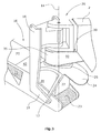
- Fig. 2 shows the transfer region from the first conveyor 10 to the second conveyor 16 in cross-section at a steep angle of inclination.
- a transfer device with a transfer element 30 and a receiving element 28 is arranged, between which a cover element 24 is provided.
- the cover element 24 has a passage opening 40, which connects a transfer opening 36 of the transfer element 30 with a receiving opening 38 of the receiving element 28.
- the transfer element 30, the cover elements 24 and the receiving element 28 form three relatively movable assemblies.
- the transfer device has a material feed area, which is formed by the transfer element 30, a sealing element, which is formed by the cover element 24 and a Materialabrated Scheme, which is formed by the receiving element 28.
- a fundamental idea is that the cover element 24 and the receiving element 28 form a spatial penetration and transport the milled material 3 from the material feed region to the material discharge region through the common cut surface.
- the cover element 24 is pivotable relative to the machine frame 2 or to the transfer element 30 about the pivot axis 14 or the receiving element 28 relative to the machine frame 2 or the cover element 24 in each case about the pivot axis 12.
- the milled material can be transferred from the first conveyor 10 to the second conveyor 16 without milled off Material 3 or dust can escape to the outside, in each pivot position and tilt position of the second conveyor 16th
- the second conveyor 16 is supported by a portal-like support structure 18, which in Fig. 2 is shown cut.
- the support structure 18 is preferably articulated by means of a bearing 26 on the machine frame 2 and can be pivoted together with the second conveyor 16 about the vertical pivot axis 14.
- At this support structure 18 at least one piston-cylinder unit 20 is hinged at the upper end, with the aid of which the desired inclination angle of the second conveyor 16 about the horizontal pivot axis 12 is adjustable.
- the horizontal pivot axis 12 is mounted in the support structure 18 at whose lower end in both sides of the second conveyor 16 arranged support arms 19.
- the displacement angle of the second conveyor 16 to the side is using the in Fig. 1 apparent piston-cylinder units 22 performed, which preferably act between the machine frame 2 and the second conveyor 16 or the support structure 18 and are arranged on both sides of the conveyor 16.
- the transfer element 30 has an inlet connection 32, which is adapted to the front end of the first conveyor 10 such that it can completely take over the milled material 3 from a conveyor belt 21 of the first conveyor 10.
- an inlet connection 32 which is adapted to the front end of the first conveyor 10 such that it can completely take over the milled material 3 from a conveyor belt 21 of the first conveyor 10.
- baffle plate or a baffle 34 may be arranged, with the aid of milled material 3 can be deflected downward.
- the inlet nozzle 32 opens into the aligned parallel to the vertical pivot axis 14 tubular, preferably circular in cross-section part 35 of the transfer member 30, wherein the inlet nozzle 32 can taper in the direction of the tubular member 35 in plan view tapered to the width of the tubular member 35.
- the tubular part 35 at least in the area of the transfer opening 36 or in the region of the engagement in or around the cover element 24, preferably has a circular-cylindrical cross-section which is concentric with the vertical pivot axis 14 in order to allow the cover element 24 to rotate relative to the transfer element 30.
- the transfer opening 36 At the lower end of the part 35 of the transfer element 30 is the transfer opening 36, which preferably extends coaxially to the vertical pivot axis 14 and preferably has a circular cross-section.
- This transfer opening 36 opens into a passage opening 40 of the cover element 24, which in turn cooperates with the receiving opening 38 of the receiving element 28.
- the receiving opening 38 extends parallel to the longitudinal extension of the second conveyor 16 and may extend substantially over the entire width of the second conveyor 16.
- the transfer opening 36 is arranged in the part 35 such that it engages in the passage opening 40 of the cover element 24 and, if necessary, also engages in the receiving opening 38 of the receiving element 28.
- the cover element 24 may have a part of the pipe 35 enclosing pipe socket 25 which is pivotable relative to the fixed part 35 about the vertical pivot axis 14.
- the lid member 24 can be pivoted together with the support structure 18 and the second conveyor 16 together laterally.
- the lid member 24 is for example fixedly attached to the support structure 18 and is therefore not pivoted at a tilt adjustment for the second conveyor 16 about the horizontal pivot axis 12.
- the receiving opening 38 extending in the longitudinal direction of the second conveying device 16 is at least partially closed by the cover element 24 in each inclined position of the second conveying device 16.
- the cover member 24 and the receiving element 28 in the in Fig. 2 shown cross-section substantially curved in a circle segment around the horizontal pivot axis 12, wherein the receiving element 28 and the cover member 24 are adapted to each other with respect to the curvature that either the cover member 24 may rest on a support structure or surface 29 of the receiving element 28 or with little mutual distance this can run. It is understood that between the cover member 24 and the receiving element 28 sealing means may be provided.
- the radius of curvature of the mating surfaces or support structures is preferably in the range between 80 and 100 cm, more preferably in the range between 80% and 120% of the width of the second conveyor 16.
- the diameter of the transfer opening 36 and the passage opening 40 is e.g. depending on the bandwidth in the range between 65 and 110 cm and preferably between about 70% and 100% of the width of the conveyor belt 23rd
- the receiving element 28 extends in the transverse direction to the second conveyor 16, preferably over its entire width, but can also taper upwards in the direction of the cover element 24.
- Fig. 3 shows a perspective view of the material transfer point between the first and second conveyor 16 at a shallow angle of inclination.
- cover element 24 can protrude to the rear when a shallow angle of inclination for the second conveyor 16 is set.
- FIG. 2 the second conveyor 16 with a steep angle of inclination.
- Fig. 3 illustrated transfer element 30 is shown an embodiment in which the walls 33 of the inlet nozzle 32 and / or the part 35 are substantially formed of a wear-resistant flexible material, for example of a fiber-reinforced elastomeric material.
- the rear wall 27 of the receiving element 28 extends at each angle of inclination of the second conveyor 16 obliquely downwards, namely rectilinear or curved, so that no milled material 3 can back up within the receiving element 28.
- a flexible sealing member 42 may be secured to the cover member 24 and slide on a cover 44 of the second conveyor 16 to keep the transitional area between the receiving member 28 and the cover 44 in each operative position.
- Fig. 4 shows a second embodiment of the transfer device, wherein the cover member 24 is integral with the transfer member 30 and insofar is not pivotable relative to the transfer member 30.
- Fig. 4 is a section in the plane of the vertical pivot axis 14th
- the transfer opening 36 coincides with the passage opening 40 and form a uniform opening which cooperates with the receiving opening 38. If the diameter of the passage opening 40 should be larger in relation to the width of the conveyor belt 23, the support arms 19 may have a larger mutual distance at least in the region of the cover element 24.
- the cover element 24 is spherically curved as part of the transfer element 30 and the receiving element 28 adapted to this spherical curvature at the top.
- the lid member 24 not attached to the portal-like support structure 18.
- the cover element 24 has an outer contour in plan view, which always covers the possible positions of the receiving opening 38 of the receiving element 28 in a lateral pivoting range of ⁇ 60 ° and in an inclination range of about 25 ° to 30 °.
- Fig. 5 shows a plan view of the embodiment of Fig. 4 , from which the different positions of the receiving opening 38 are shown in dashed lines depending on the lateral pivot position and angle of inclination of the second conveyor 16. Furthermore, an example of the outer contour of the cover element 24 is shown.
- Fig. 5 shows a position with a shallow inclination angle of the second conveyor 16.
Landscapes
- Engineering & Computer Science (AREA)
- Mining & Mineral Resources (AREA)
- Architecture (AREA)
- Civil Engineering (AREA)
- Structural Engineering (AREA)
- Mechanical Engineering (AREA)
- Disintegrating Or Milling (AREA)
- Filling Or Emptying Of Bunkers, Hoppers, And Tanks (AREA)
- Auxiliary Methods And Devices For Loading And Unloading (AREA)
- Framework For Endless Conveyors (AREA)
Applications Claiming Priority (1)
| Application Number | Priority Date | Filing Date | Title |
|---|---|---|---|
| DE102015212902.0A DE102015212902A1 (de) | 2015-07-09 | 2015-07-09 | Fräsmaschine zum Bearbeiten von Bodenoberflächen, Übergabeeinrichtung, sowie Verfahren zur Übergabe von abgefrästem Material |
Publications (2)
| Publication Number | Publication Date |
|---|---|
| EP3115508A1 true EP3115508A1 (fr) | 2017-01-11 |
| EP3115508B1 EP3115508B1 (fr) | 2018-04-18 |
Family
ID=56368855
Family Applications (1)
| Application Number | Title | Priority Date | Filing Date |
|---|---|---|---|
| EP16177789.1A Active EP3115508B1 (fr) | 2015-07-09 | 2016-07-04 | Fraiseuse destinée à usiner des surfaces de sol, dispositif de transfert et procédé de transfert de matériau fraisé |
Country Status (4)
| Country | Link |
|---|---|
| US (1) | US10227740B2 (fr) |
| EP (1) | EP3115508B1 (fr) |
| CN (2) | CN206090263U (fr) |
| DE (1) | DE102015212902A1 (fr) |
Cited By (1)
| Publication number | Priority date | Publication date | Assignee | Title |
|---|---|---|---|---|
| EP3868958A1 (fr) | 2020-02-21 | 2021-08-25 | BOMAG GmbH | Dispositif de déversement de matériau pour une machine fraiseuse de sol |
Families Citing this family (10)
| Publication number | Priority date | Publication date | Assignee | Title |
|---|---|---|---|---|
| DE102015212902A1 (de) * | 2015-07-09 | 2017-01-12 | Wirtgen Gmbh | Fräsmaschine zum Bearbeiten von Bodenoberflächen, Übergabeeinrichtung, sowie Verfahren zur Übergabe von abgefrästem Material |
| DE102017000212A1 (de) | 2017-01-13 | 2018-07-19 | Dynapac Gmbh | Straßenbaumaschine und Verfahren zum Betreiben einer Straßenbaumaschine |
| CN107165034A (zh) * | 2017-07-18 | 2017-09-15 | 湖南煜欣轨道装备科技工程有限公司 | 一种铣刨机 |
| US10428471B1 (en) * | 2018-05-22 | 2019-10-01 | Caterpillar Paving Products Inc. | Systems and methods for controlling cold planer material flow |
| US10583995B2 (en) * | 2018-06-26 | 2020-03-10 | Caterpillar Paving Products, Inc. | Flexible hopper for a conveyor system |
| US10589933B2 (en) | 2018-06-26 | 2020-03-17 | Caterpillar Paving Products Inc. | Flexible hopper for a conveyor system |
| US11072894B2 (en) | 2019-07-16 | 2021-07-27 | Caterpillar Paving Products Inc. | Milling assembly material flow control system |
| CN110438877B (zh) * | 2019-08-23 | 2021-04-30 | 杭州曼京科技有限公司 | 一种绿色建筑使用的回收道路沥青垃圾的装置 |
| DE102021119491A1 (de) | 2020-08-07 | 2022-02-10 | Bomag Gmbh | BODENFRÄSMASCHINE, INSBESONDERE STRAßENFRÄSE, MIT EINER FÖRDEREINRICHTUNG ZUM TRANSPORT VON FRÄSGUT SOWIE VERFAHREN ZUM FÖRDERN VON FRÄSGUT EINER BODENFRÄSMASCHINE |
| CN112275062B (zh) * | 2020-10-28 | 2021-12-28 | 山东省大通公路工程有限责任公司 | 一种老路病害修复施工用的铣刨机降尘设备 |
Citations (6)
| Publication number | Priority date | Publication date | Assignee | Title |
|---|---|---|---|---|
| US20070122236A1 (en) * | 2002-05-28 | 2007-05-31 | Olaf Gaertner | Milling machine for machining ground surfaces as well as a method for the disposal of dusts and fumes produced during the milling at a milling machine |
| EP1936034A2 (fr) | 2006-12-22 | 2008-06-25 | WIRTGEN GmbH | Machine de construction de routes et procédé de mesure de la profondeur de la fraise |
| EP2236745A2 (fr) | 2009-03-20 | 2010-10-06 | Wirtgen GmbH | Engin d'abatage, notamment Surface Miner, ainsi que procédé de démontage et de montage d'un dispositif de transport pour engin d'abatage |
| EP2350390A1 (fr) | 2008-10-21 | 2011-08-03 | Marini S.p.A. | Machine à niveler les chaussées pour fraiser les surfaces de roulement |
| US20110272511A1 (en) * | 2010-05-06 | 2011-11-10 | Hall David R | Dust Reduction Mechanism in an Aggregate Removal System |
| DE102012019016A1 (de) | 2012-09-26 | 2014-04-10 | Bomag Gmbh | Materialübergabevorrichtung für eine Bodenfräsmaschine und Bodenfräsmaschine, insbesondere Straßenfräse mit einer solchen Materialübergabevorrichtung |
Family Cites Families (10)
| Publication number | Priority date | Publication date | Assignee | Title |
|---|---|---|---|---|
| US2360069A (en) * | 1943-02-08 | 1944-10-10 | Super Mold Corp | Conveyer mounting and feed unit |
| US3187910A (en) * | 1962-02-26 | 1965-06-08 | Fmc Corp | Bulk tank truck and discharge means therefor |
| US3744615A (en) * | 1970-09-25 | 1973-07-10 | J Plaquet | Installation for the evacuation of rocks from a working to a continuous transporter |
| BE789358A (fr) * | 1971-09-27 | 1973-03-27 | Valkenburgh Bryce F Van | Excavatrice |
| US4419037A (en) * | 1980-12-30 | 1983-12-06 | Niewold Donald W | Truck auger-hopper construction |
| US5409344A (en) * | 1994-03-07 | 1995-04-25 | United Farm Tools, Inc. | Portable grain cart auger system |
| CA2153935C (fr) * | 1994-08-22 | 2001-06-12 | Maurice Grieshop | Vis sans fin de manutention pour wagon a cereales |
| EP2265765B1 (fr) * | 2008-03-12 | 2014-12-03 | Marini S.p.A. | Fraiseuse de route améliorée |
| ES2683696T3 (es) * | 2013-10-16 | 2018-09-27 | Roadtec, Inc | Máquina de trabajo y método para hacer funcionar una máquina de trabajo con control de emisiones de polvo |
| DE102015212902A1 (de) * | 2015-07-09 | 2017-01-12 | Wirtgen Gmbh | Fräsmaschine zum Bearbeiten von Bodenoberflächen, Übergabeeinrichtung, sowie Verfahren zur Übergabe von abgefrästem Material |
-
2015
- 2015-07-09 DE DE102015212902.0A patent/DE102015212902A1/de not_active Withdrawn
-
2016
- 2016-07-04 EP EP16177789.1A patent/EP3115508B1/fr active Active
- 2016-07-05 US US15/201,839 patent/US10227740B2/en active Active
- 2016-07-11 CN CN201620722432.8U patent/CN206090263U/zh not_active Withdrawn - After Issue
- 2016-07-11 CN CN201610539386.2A patent/CN106337356B/zh active Active
Patent Citations (6)
| Publication number | Priority date | Publication date | Assignee | Title |
|---|---|---|---|---|
| US20070122236A1 (en) * | 2002-05-28 | 2007-05-31 | Olaf Gaertner | Milling machine for machining ground surfaces as well as a method for the disposal of dusts and fumes produced during the milling at a milling machine |
| EP1936034A2 (fr) | 2006-12-22 | 2008-06-25 | WIRTGEN GmbH | Machine de construction de routes et procédé de mesure de la profondeur de la fraise |
| EP2350390A1 (fr) | 2008-10-21 | 2011-08-03 | Marini S.p.A. | Machine à niveler les chaussées pour fraiser les surfaces de roulement |
| EP2236745A2 (fr) | 2009-03-20 | 2010-10-06 | Wirtgen GmbH | Engin d'abatage, notamment Surface Miner, ainsi que procédé de démontage et de montage d'un dispositif de transport pour engin d'abatage |
| US20110272511A1 (en) * | 2010-05-06 | 2011-11-10 | Hall David R | Dust Reduction Mechanism in an Aggregate Removal System |
| DE102012019016A1 (de) | 2012-09-26 | 2014-04-10 | Bomag Gmbh | Materialübergabevorrichtung für eine Bodenfräsmaschine und Bodenfräsmaschine, insbesondere Straßenfräse mit einer solchen Materialübergabevorrichtung |
Cited By (3)
| Publication number | Priority date | Publication date | Assignee | Title |
|---|---|---|---|---|
| EP3868958A1 (fr) | 2020-02-21 | 2021-08-25 | BOMAG GmbH | Dispositif de déversement de matériau pour une machine fraiseuse de sol |
| DE102020001163A1 (de) | 2020-02-21 | 2021-08-26 | Bomag Gmbh | Materialübergabevorrichtung für eine bodenfräsmaschine und bodenfräsmaschine mit derartiger materialübergabevorrichtung |
| US11668057B2 (en) | 2020-02-21 | 2023-06-06 | Bomag Gmbh | Material transfer apparatus for a ground milling machine and ground milling machine having such a material transfer apparatus |
Also Published As
| Publication number | Publication date |
|---|---|
| US10227740B2 (en) | 2019-03-12 |
| CN106337356A (zh) | 2017-01-18 |
| CN106337356B (zh) | 2019-04-30 |
| US20170009409A1 (en) | 2017-01-12 |
| EP3115508B1 (fr) | 2018-04-18 |
| DE102015212902A1 (de) | 2017-01-12 |
| CN206090263U (zh) | 2017-04-12 |
Similar Documents
| Publication | Publication Date | Title |
|---|---|---|
| EP3115508B1 (fr) | Fraiseuse destinée à usiner des surfaces de sol, dispositif de transfert et procédé de transfert de matériau fraisé | |
| DE3909741C2 (de) | Gliederbandförderer | |
| DE102008021484A1 (de) | Knickbares Transportband für eine Baumaschine, selbstfahrende Baumaschine und Verfahren zum Verschwenken eines Transportbandes | |
| DE2319910A1 (de) | Einrichtung zur niveausteuerung einer gewinnungsmaschine, insbesondere eines hobels | |
| DE3237801C2 (de) | Verfahrbare Schrämmaschine | |
| WO2013131726A1 (fr) | Fraiseuse routière automotrice destinée à usiner des surfaces routières, et procédé d'usinage de surfaces routières | |
| EP3528955B1 (fr) | Trémie d'alimentation à verrouillage automatique | |
| EP1841637B1 (fr) | Machine de construction et dispositif de rotation | |
| AT506917B1 (de) | Gurtlenkvorrichtung für schlauchgurtförderer | |
| EP3686345A1 (fr) | Finisseuse de route pourvue de déflecteur de matériau pivotant | |
| DE9213091U1 (de) | Kreiselegge | |
| DE102007006795B3 (de) | Einrichtung zur staubfreien Schüttgutübergabe | |
| EP3613900A1 (fr) | Machine de traitement du sol pourvue de dispositif de transport pouvant être rapidement enlevé du groupe de fraisage et procédé correspondant | |
| DE3339929C2 (fr) | ||
| DE10221253A1 (de) | Vorrichtung zum Sieben, Sortieren oder Zerkleinern von schüttfähigen Gütern | |
| EP0111882A2 (fr) | Chasse-neige | |
| DE2615629A1 (de) | Grubenausbaugestell | |
| DE2455767B1 (de) | Vorrichtung zum verteilen des beschickungsgutes in schachtoefen, insbesondere hochdruck-hochoefen | |
| DE1172549B (de) | Vorrichtung zur Spurweitenveraenderung der Lauf- oder Kettenraeder nicht schienen-gebundener Fahrzeuge | |
| DE3904756A1 (de) | Drehgelenk fuer niederflur-gelenkomnibusse | |
| DE3327202A1 (de) | Bandabsetzer | |
| DE19921131A1 (de) | Weiche für eine Förderanlage, insbesondere für einen Rollenförderer | |
| DE2601001C2 (fr) | ||
| EP3492657B1 (fr) | Machine de marquage permettant de générer des lignes de marquage sur des surfaces de circulation | |
| AT525876B1 (de) | Mobile Vorrichtung zur Materialverarbeitung |
Legal Events
| Date | Code | Title | Description |
|---|---|---|---|
| PUAI | Public reference made under article 153(3) epc to a published international application that has entered the european phase |
Free format text: ORIGINAL CODE: 0009012 |
|
| AK | Designated contracting states |
Kind code of ref document: A1 Designated state(s): AL AT BE BG CH CY CZ DE DK EE ES FI FR GB GR HR HU IE IS IT LI LT LU LV MC MK MT NL NO PL PT RO RS SE SI SK SM TR |
|
| AX | Request for extension of the european patent |
Extension state: BA ME |
|
| 17P | Request for examination filed |
Effective date: 20170711 |
|
| RBV | Designated contracting states (corrected) |
Designated state(s): AL AT BE BG CH CY CZ DE DK EE ES FI FR GB GR HR HU IE IS IT LI LT LU LV MC MK MT NL NO PL PT RO RS SE SI SK SM TR |
|
| GRAP | Despatch of communication of intention to grant a patent |
Free format text: ORIGINAL CODE: EPIDOSNIGR1 |
|
| INTG | Intention to grant announced |
Effective date: 20171102 |
|
| GRAS | Grant fee paid |
Free format text: ORIGINAL CODE: EPIDOSNIGR3 |
|
| GRAA | (expected) grant |
Free format text: ORIGINAL CODE: 0009210 |
|
| AK | Designated contracting states |
Kind code of ref document: B1 Designated state(s): AL AT BE BG CH CY CZ DE DK EE ES FI FR GB GR HR HU IE IS IT LI LT LU LV MC MK MT NL NO PL PT RO RS SE SI SK SM TR |
|
| REG | Reference to a national code |
Ref country code: GB Ref legal event code: FG4D Free format text: NOT ENGLISH |
|
| REG | Reference to a national code |
Ref country code: CH Ref legal event code: EP |
|
| REG | Reference to a national code |
Ref country code: AT Ref legal event code: REF Ref document number: 990617 Country of ref document: AT Kind code of ref document: T Effective date: 20180515 |
|
| REG | Reference to a national code |
Ref country code: IE Ref legal event code: FG4D Free format text: LANGUAGE OF EP DOCUMENT: GERMAN |
|
| REG | Reference to a national code |
Ref country code: DE Ref legal event code: R096 Ref document number: 502016000906 Country of ref document: DE |
|
| REG | Reference to a national code |
Ref country code: FR Ref legal event code: PLFP Year of fee payment: 3 |
|
| REG | Reference to a national code |
Ref country code: SE Ref legal event code: TRGR |
|
| REG | Reference to a national code |
Ref country code: NL Ref legal event code: MP Effective date: 20180418 |
|
| REG | Reference to a national code |
Ref country code: LT Ref legal event code: MG4D |
|
| PG25 | Lapsed in a contracting state [announced via postgrant information from national office to epo] |
Ref country code: NL Free format text: LAPSE BECAUSE OF FAILURE TO SUBMIT A TRANSLATION OF THE DESCRIPTION OR TO PAY THE FEE WITHIN THE PRESCRIBED TIME-LIMIT Effective date: 20180418 |
|
| PG25 | Lapsed in a contracting state [announced via postgrant information from national office to epo] |
Ref country code: PL Free format text: LAPSE BECAUSE OF FAILURE TO SUBMIT A TRANSLATION OF THE DESCRIPTION OR TO PAY THE FEE WITHIN THE PRESCRIBED TIME-LIMIT Effective date: 20180418 Ref country code: FI Free format text: LAPSE BECAUSE OF FAILURE TO SUBMIT A TRANSLATION OF THE DESCRIPTION OR TO PAY THE FEE WITHIN THE PRESCRIBED TIME-LIMIT Effective date: 20180418 Ref country code: BG Free format text: LAPSE BECAUSE OF FAILURE TO SUBMIT A TRANSLATION OF THE DESCRIPTION OR TO PAY THE FEE WITHIN THE PRESCRIBED TIME-LIMIT Effective date: 20180718 Ref country code: NO Free format text: LAPSE BECAUSE OF FAILURE TO SUBMIT A TRANSLATION OF THE DESCRIPTION OR TO PAY THE FEE WITHIN THE PRESCRIBED TIME-LIMIT Effective date: 20180718 Ref country code: AL Free format text: LAPSE BECAUSE OF FAILURE TO SUBMIT A TRANSLATION OF THE DESCRIPTION OR TO PAY THE FEE WITHIN THE PRESCRIBED TIME-LIMIT Effective date: 20180418 Ref country code: LT Free format text: LAPSE BECAUSE OF FAILURE TO SUBMIT A TRANSLATION OF THE DESCRIPTION OR TO PAY THE FEE WITHIN THE PRESCRIBED TIME-LIMIT Effective date: 20180418 Ref country code: ES Free format text: LAPSE BECAUSE OF FAILURE TO SUBMIT A TRANSLATION OF THE DESCRIPTION OR TO PAY THE FEE WITHIN THE PRESCRIBED TIME-LIMIT Effective date: 20180418 |
|
| REG | Reference to a national code |
Ref country code: CH Ref legal event code: PK Free format text: BERICHTIGUNGEN |
|
| PG25 | Lapsed in a contracting state [announced via postgrant information from national office to epo] |
Ref country code: HR Free format text: LAPSE BECAUSE OF FAILURE TO SUBMIT A TRANSLATION OF THE DESCRIPTION OR TO PAY THE FEE WITHIN THE PRESCRIBED TIME-LIMIT Effective date: 20180418 Ref country code: GR Free format text: LAPSE BECAUSE OF FAILURE TO SUBMIT A TRANSLATION OF THE DESCRIPTION OR TO PAY THE FEE WITHIN THE PRESCRIBED TIME-LIMIT Effective date: 20180719 Ref country code: LV Free format text: LAPSE BECAUSE OF FAILURE TO SUBMIT A TRANSLATION OF THE DESCRIPTION OR TO PAY THE FEE WITHIN THE PRESCRIBED TIME-LIMIT Effective date: 20180418 Ref country code: RS Free format text: LAPSE BECAUSE OF FAILURE TO SUBMIT A TRANSLATION OF THE DESCRIPTION OR TO PAY THE FEE WITHIN THE PRESCRIBED TIME-LIMIT Effective date: 20180418 |
|
| RIN2 | Information on inventor provided after grant (corrected) |
Inventor name: HAEHN, GUENTER Inventor name: VERHAELEN, PHILIP Inventor name: SCHMITZ, KEVIN HELMUT Inventor name: SCHINGS, BASTIAN Inventor name: VON DER BEEK, FELIX JOHANNES Inventor name: BARIMANI, CYRUS Inventor name: WAGNER, JURI Inventor name: JENTSCH, STEFAN |
|
| RIN2 | Information on inventor provided after grant (corrected) |
Inventor name: SCHINGS, BASTIAN Inventor name: SCHMITZ, KEVIN HELMUT Inventor name: VAN DER BEEK, FELIX JOHANNES Inventor name: BARIMANI, CYRUS Inventor name: HAEHN, GUENTER Inventor name: VERHAELEN, PHILIP Inventor name: JENTSCH, STEFAN Inventor name: WAGNER, JURI |
|
| PG25 | Lapsed in a contracting state [announced via postgrant information from national office to epo] |
Ref country code: PT Free format text: LAPSE BECAUSE OF FAILURE TO SUBMIT A TRANSLATION OF THE DESCRIPTION OR TO PAY THE FEE WITHIN THE PRESCRIBED TIME-LIMIT Effective date: 20180820 |
|
| REG | Reference to a national code |
Ref country code: GB Ref legal event code: S13A Free format text: APPLICATION FILED; APPLICATION UNDER RULE 10(2) FOR INVENTOR TO BE MENTIONED FILED ON 23 NOVEMBER 2018 BY WIRTGEN GMBH |
|
| REG | Reference to a national code |
Ref country code: DE Ref legal event code: R097 Ref document number: 502016000906 Country of ref document: DE |
|
| PG25 | Lapsed in a contracting state [announced via postgrant information from national office to epo] |
Ref country code: DK Free format text: LAPSE BECAUSE OF FAILURE TO SUBMIT A TRANSLATION OF THE DESCRIPTION OR TO PAY THE FEE WITHIN THE PRESCRIBED TIME-LIMIT Effective date: 20180418 Ref country code: CZ Free format text: LAPSE BECAUSE OF FAILURE TO SUBMIT A TRANSLATION OF THE DESCRIPTION OR TO PAY THE FEE WITHIN THE PRESCRIBED TIME-LIMIT Effective date: 20180418 Ref country code: EE Free format text: LAPSE BECAUSE OF FAILURE TO SUBMIT A TRANSLATION OF THE DESCRIPTION OR TO PAY THE FEE WITHIN THE PRESCRIBED TIME-LIMIT Effective date: 20180418 Ref country code: RO Free format text: LAPSE BECAUSE OF FAILURE TO SUBMIT A TRANSLATION OF THE DESCRIPTION OR TO PAY THE FEE WITHIN THE PRESCRIBED TIME-LIMIT Effective date: 20180418 Ref country code: SK Free format text: LAPSE BECAUSE OF FAILURE TO SUBMIT A TRANSLATION OF THE DESCRIPTION OR TO PAY THE FEE WITHIN THE PRESCRIBED TIME-LIMIT Effective date: 20180418 |
|
| REG | Reference to a national code |
Ref country code: GB Ref legal event code: S13A Free format text: APPLICATION ALLOWED; IN A DECISION OF THE COMPTROLLER DATED 18 JANUARY 2019, THE COMPTROLLER FOUND THAT JURI WAGNER, STEFAN JENTSCH, BASTIAN SCHINGS, DR. KEVIN HEMUT SCHMITZ AND DR. FELIX JOHANNES VAN DER BEEK SHOULD BE MENTIONED AS JOINT INVENTORS. IT WAS DIRECTED THAT AN ADDENDUM SLIP BE PREPARED FOR THE GRANTED PATENT FOR THE INVENTION. |
|
| PLBE | No opposition filed within time limit |
Free format text: ORIGINAL CODE: 0009261 |
|
| STAA | Information on the status of an ep patent application or granted ep patent |
Free format text: STATUS: NO OPPOSITION FILED WITHIN TIME LIMIT |
|
| PG25 | Lapsed in a contracting state [announced via postgrant information from national office to epo] |
Ref country code: SM Free format text: LAPSE BECAUSE OF FAILURE TO SUBMIT A TRANSLATION OF THE DESCRIPTION OR TO PAY THE FEE WITHIN THE PRESCRIBED TIME-LIMIT Effective date: 20180418 |
|
| 26N | No opposition filed |
Effective date: 20190121 |
|
| PG25 | Lapsed in a contracting state [announced via postgrant information from national office to epo] |
Ref country code: LU Free format text: LAPSE BECAUSE OF NON-PAYMENT OF DUE FEES Effective date: 20180704 Ref country code: MC Free format text: LAPSE BECAUSE OF FAILURE TO SUBMIT A TRANSLATION OF THE DESCRIPTION OR TO PAY THE FEE WITHIN THE PRESCRIBED TIME-LIMIT Effective date: 20180418 |
|
| REG | Reference to a national code |
Ref country code: BE Ref legal event code: MM Effective date: 20180731 |
|
| REG | Reference to a national code |
Ref country code: IE Ref legal event code: MM4A |
|
| PG25 | Lapsed in a contracting state [announced via postgrant information from national office to epo] |
Ref country code: IE Free format text: LAPSE BECAUSE OF NON-PAYMENT OF DUE FEES Effective date: 20180704 |
|
| PG25 | Lapsed in a contracting state [announced via postgrant information from national office to epo] |
Ref country code: SI Free format text: LAPSE BECAUSE OF FAILURE TO SUBMIT A TRANSLATION OF THE DESCRIPTION OR TO PAY THE FEE WITHIN THE PRESCRIBED TIME-LIMIT Effective date: 20180418 Ref country code: BE Free format text: LAPSE BECAUSE OF NON-PAYMENT OF DUE FEES Effective date: 20180731 |
|
| PG25 | Lapsed in a contracting state [announced via postgrant information from national office to epo] |
Ref country code: MT Free format text: LAPSE BECAUSE OF FAILURE TO SUBMIT A TRANSLATION OF THE DESCRIPTION OR TO PAY THE FEE WITHIN THE PRESCRIBED TIME-LIMIT Effective date: 20180418 |
|
| REG | Reference to a national code |
Ref country code: CH Ref legal event code: PL |
|
| PG25 | Lapsed in a contracting state [announced via postgrant information from national office to epo] |
Ref country code: TR Free format text: LAPSE BECAUSE OF FAILURE TO SUBMIT A TRANSLATION OF THE DESCRIPTION OR TO PAY THE FEE WITHIN THE PRESCRIBED TIME-LIMIT Effective date: 20180418 |
|
| PG25 | Lapsed in a contracting state [announced via postgrant information from national office to epo] |
Ref country code: LI Free format text: LAPSE BECAUSE OF NON-PAYMENT OF DUE FEES Effective date: 20190731 Ref country code: CH Free format text: LAPSE BECAUSE OF NON-PAYMENT OF DUE FEES Effective date: 20190731 |
|
| PG25 | Lapsed in a contracting state [announced via postgrant information from national office to epo] |
Ref country code: CY Free format text: LAPSE BECAUSE OF FAILURE TO SUBMIT A TRANSLATION OF THE DESCRIPTION OR TO PAY THE FEE WITHIN THE PRESCRIBED TIME-LIMIT Effective date: 20180418 Ref country code: MK Free format text: LAPSE BECAUSE OF NON-PAYMENT OF DUE FEES Effective date: 20180418 Ref country code: HU Free format text: LAPSE BECAUSE OF FAILURE TO SUBMIT A TRANSLATION OF THE DESCRIPTION OR TO PAY THE FEE WITHIN THE PRESCRIBED TIME-LIMIT; INVALID AB INITIO Effective date: 20160704 |
|
| PG25 | Lapsed in a contracting state [announced via postgrant information from national office to epo] |
Ref country code: IS Free format text: LAPSE BECAUSE OF FAILURE TO SUBMIT A TRANSLATION OF THE DESCRIPTION OR TO PAY THE FEE WITHIN THE PRESCRIBED TIME-LIMIT Effective date: 20180818 |
|
| REG | Reference to a national code |
Ref country code: AT Ref legal event code: MM01 Ref document number: 990617 Country of ref document: AT Kind code of ref document: T Effective date: 20210704 |
|
| PG25 | Lapsed in a contracting state [announced via postgrant information from national office to epo] |
Ref country code: AT Free format text: LAPSE BECAUSE OF NON-PAYMENT OF DUE FEES Effective date: 20210704 |
|
| P01 | Opt-out of the competence of the unified patent court (upc) registered |
Effective date: 20230525 |
|
| PGFP | Annual fee paid to national office [announced via postgrant information from national office to epo] |
Ref country code: IT Payment date: 20230731 Year of fee payment: 8 Ref country code: GB Payment date: 20230724 Year of fee payment: 8 |
|
| PGFP | Annual fee paid to national office [announced via postgrant information from national office to epo] |
Ref country code: SE Payment date: 20230724 Year of fee payment: 8 Ref country code: FR Payment date: 20230724 Year of fee payment: 8 Ref country code: DE Payment date: 20230720 Year of fee payment: 8 |