EP3110701B2 - Behälterinspektionsvorrichtung - Google Patents
Behälterinspektionsvorrichtung Download PDFInfo
- Publication number
- EP3110701B2 EP3110701B2 EP15706436.1A EP15706436A EP3110701B2 EP 3110701 B2 EP3110701 B2 EP 3110701B2 EP 15706436 A EP15706436 A EP 15706436A EP 3110701 B2 EP3110701 B2 EP 3110701B2
- Authority
- EP
- European Patent Office
- Prior art keywords
- container
- control module
- camera
- inspection
- handling system
- Prior art date
- Legal status (The legal status is an assumption and is not a legal conclusion. Google has not performed a legal analysis and makes no representation as to the accuracy of the status listed.)
- Active
Links
Images
Classifications
-
- B—PERFORMING OPERATIONS; TRANSPORTING
- B65—CONVEYING; PACKING; STORING; HANDLING THIN OR FILAMENTARY MATERIAL
- B65C—LABELLING OR TAGGING MACHINES, APPARATUS, OR PROCESSES
- B65C9/00—Details of labelling machines or apparatus
- B65C9/40—Controls; Safety devices
-
- B—PERFORMING OPERATIONS; TRANSPORTING
- B67—OPENING, CLOSING OR CLEANING BOTTLES, JARS OR SIMILAR CONTAINERS; LIQUID HANDLING
- B67B—APPLYING CLOSURE MEMBERS TO BOTTLES JARS, OR SIMILAR CONTAINERS; OPENING CLOSED CONTAINERS
- B67B3/00—Closing bottles, jars or similar containers by applying caps
- B67B3/26—Applications of control, warning, or safety devices in capping machinery
- B67B3/262—Devices for controlling the caps
-
- B—PERFORMING OPERATIONS; TRANSPORTING
- B67—OPENING, CLOSING OR CLEANING BOTTLES, JARS OR SIMILAR CONTAINERS; LIQUID HANDLING
- B67C—CLEANING, FILLING WITH LIQUIDS OR SEMILIQUIDS, OR EMPTYING, OF BOTTLES, JARS, CANS, CASKS, BARRELS, OR SIMILAR CONTAINERS, NOT OTHERWISE PROVIDED FOR; FUNNELS
- B67C3/00—Bottling liquids or semiliquids; Filling jars or cans with liquids or semiliquids using bottling or like apparatus; Filling casks or barrels with liquids or semiliquids
- B67C3/007—Applications of control, warning or safety devices in filling machinery
-
- G—PHYSICS
- G01—MEASURING; TESTING
- G01N—INVESTIGATING OR ANALYSING MATERIALS BY DETERMINING THEIR CHEMICAL OR PHYSICAL PROPERTIES
- G01N21/00—Investigating or analysing materials by the use of optical means, i.e. using sub-millimetre waves, infrared, visible or ultraviolet light
- G01N21/84—Systems specially adapted for particular applications
- G01N21/88—Investigating the presence of flaws or contamination
- G01N21/90—Investigating the presence of flaws or contamination in a container or its contents
- G01N21/9009—Non-optical constructional details affecting optical inspection, e.g. cleaning mechanisms for optical parts, vibration reduction
-
- G—PHYSICS
- G06—COMPUTING OR CALCULATING; COUNTING
- G06T—IMAGE DATA PROCESSING OR GENERATION, IN GENERAL
- G06T7/00—Image analysis
- G06T7/0002—Inspection of images, e.g. flaw detection
- G06T7/0004—Industrial image inspection
-
- G—PHYSICS
- G06—COMPUTING OR CALCULATING; COUNTING
- G06T—IMAGE DATA PROCESSING OR GENERATION, IN GENERAL
- G06T7/00—Image analysis
- G06T7/70—Determining position or orientation of objects or cameras
-
- G—PHYSICS
- G06—COMPUTING OR CALCULATING; COUNTING
- G06V—IMAGE OR VIDEO RECOGNITION OR UNDERSTANDING
- G06V30/00—Character recognition; Recognising digital ink; Document-oriented image-based pattern recognition
- G06V30/10—Character recognition
- G06V30/22—Character recognition characterised by the type of writing
- G06V30/224—Character recognition characterised by the type of writing of printed characters having additional code marks or containing code marks
-
- H—ELECTRICITY
- H04—ELECTRIC COMMUNICATION TECHNIQUE
- H04N—PICTORIAL COMMUNICATION, e.g. TELEVISION
- H04N23/00—Cameras or camera modules comprising electronic image sensors; Control thereof
- H04N23/50—Constructional details
- H04N23/51—Housings
-
- H—ELECTRICITY
- H04—ELECTRIC COMMUNICATION TECHNIQUE
- H04N—PICTORIAL COMMUNICATION, e.g. TELEVISION
- H04N23/00—Cameras or camera modules comprising electronic image sensors; Control thereof
- H04N23/90—Arrangement of cameras or camera modules, e.g. multiple cameras in TV studios or sports stadiums
-
- B—PERFORMING OPERATIONS; TRANSPORTING
- B65—CONVEYING; PACKING; STORING; HANDLING THIN OR FILAMENTARY MATERIAL
- B65C—LABELLING OR TAGGING MACHINES, APPARATUS, OR PROCESSES
- B65C9/00—Details of labelling machines or apparatus
- B65C9/40—Controls; Safety devices
- B65C2009/402—Controls; Safety devices for detecting properties or defects of labels
- B65C2009/407—Controls; Safety devices for detecting properties or defects of labels after labelling
-
- G—PHYSICS
- G06—COMPUTING OR CALCULATING; COUNTING
- G06T—IMAGE DATA PROCESSING OR GENERATION, IN GENERAL
- G06T2207/00—Indexing scheme for image analysis or image enhancement
- G06T2207/30—Subject of image; Context of image processing
- G06T2207/30108—Industrial image inspection
Definitions
- the invention relates to a container treatment plant with an inspection device for checking containers and a container transport device for moving the containers into an inspection position of the inspection device.
- a container When a container is passed through a container processing plant with different work stations, it is common to check various characteristics of the container. For example, the filling quantity of the container, the position of a label on the container or the position of a container closure or a logo on the container closure can be checked.
- a modular inspection device with particularly easily exchangeable control stations is available from the EN 10 2010 043 635 A1 known.
- EP 1 715 328 A1 discloses an inspection device that allows an improved reception of the container in an enclosure.
- the EP 1 715 328 A1 a special interior design of the enclosure.
- the EN 10 2008 062 385 A1 discloses a device for optically checking an original locking ring on the closures of containers.
- the EN 10 2008 034 744 A1 describes control devices for determining whether labels are correctly positioned on containers.
- EP 2 450 695 A1 discloses a device for inspecting containers with a support frame on which several control modules can be arranged that have different control functions, such as the container side wall, closure or filling state.
- Each control module represents a separate unit that controls a specific container feature.
- the control modules can be attached to the fastening device of the support frame next to each other in any position.
- particularly large control modules for example, can also be mounted on the side of the support frame.
- Each control module acts independently and detects the container in an inspection position assigned to the individual control module.
- the invention is therefore based on the object of providing a container treatment plant with a particularly compact inspection device designed to check a plurality of container features, with which a selectable number of different container features can be determined and which enables a high throughput speed of the container.
- Combining at least three control modules into one structural unit enables the inspection device to be designed to be particularly compact. This significantly reduces the installation space required for the inspection device and makes it particularly easy to arrange the inspection device in the container treatment system and in particular in a container transport path, i.e. along a transport path of the container through the container treatment system.
- the inspection device with at least three control modules enables a particularly wide range of possible applications.
- the assembly can be arranged in a variety of different positions along the transport route and enables a number of options for checking the container features on a particularly short section of the transport route.
- the containers are, for example, beverage containers. These can in particular be beverage bottles made of plastic or glass, which are, for example, at least partially transparent.
- a container treatment system can be understood as a single container processing station or a large number of container processing stations through which the container passes one after the other.
- the container transport system is designed to guide the container through the container treatment system, i.e. through or past the individual stations of the container treatment system.
- the container transport system has in particular a large number of conveyors for linear or curved transport of the containers or also transport stars for transporting the containers on a circular path.
- the container transport device therefore transports the containers along a container transport path through the container treatment system.
- the inspection position is understood to be the position of the container in which a control module can inspect the container, i.e., for example, check, record or determine a feature of the container.
- the features include in particular markings, embossings, codes, labels or properties of the container body itself that are incorporated into or attached to the container, but also features such as the fill level of a container.
- a control module is understood to be a device that inspects an actual state of one of the features of the container and, if necessary with the aid of an evaluation or control unit, compares it with a target state.
- control modules are designed in particular for optical detection, i.e. for the image detection of a feature. However, depending on the features to be detected, the control module can also have other sensors for inspecting a feature.
- At least three, preferably at least four or particularly preferably at least five control modules are combined to form a structural unit.
- the container flow is slowed down or stopped briefly, at least in the area of the inspection position.
- the container can be detected in the inspection position by at least three control modules, preferably at least four control modules, preferably at least five control modules.
- Inspecting the container using multiple control modules in a single inspection position is particularly advantageous, as the speed at which the containers pass through is hardly reduced.
- the container can be inspected by multiple control modules at the same time, for example.
- the individual control modules can also all carry out the inspection process on the container one after the other.
- the containers are usually guided past the control modules for inspection.
- the container transport device has a container transport path leading through the inspection device, along which the container is transported through the inspection device. This means that the containers are guided through the inspection device and thus either through the control modules and/or along them.
- control modules are designed in particular for optical inspection of the containers.
- the control modules can in particular create an image of the container or a container section with the feature to be inspected.
- the inspection device has a means of illumination, in particular a transmitted light for shining through the container, a ring light and/or a reflected light for illuminating the container.
- the lighting means can be arranged and designed in such a way that it provides sufficient light for all control modules included in the structural unit.
- the individual lighting means can be designed to provide a special lighting situation for one or more control modules.
- the lighting means can therefore be arranged separately from one another and can be controlled separately. They are briefly activated in particular at the time of the inspection process of the respective control module. It is also possible, for example, to activate different lighting means, such as the ring light and the incident light, simultaneously during the inspection process of one control module or several control modules. Consequently, it is also possible to control the lighting means in such a way that individual lighting means are not activated during the inspection process of a control module, while other lighting means are activated.
- the ring illumination is particularly preferably arranged coaxially around a longitudinal axis of the container in the inspection position.
- the ring lighting is arranged in particular in a plane above the container.
- the ring lighting thus enables uniform illumination of the container or at least an upper container section, such as a bottle neck and/or a container closure, from all sides.
- the incident light particularly preferably has two luminous bodies arranged at a distance from one another on a first side of the container transport path.
- the luminous elements are arranged, for example, in such a way that they are arranged in the area of a label and here in particular on an upper edge and on a lower edge of a label.
- the luminous elements extend in particular transversely to the longitudinal axis of the container, so that it is ensured that the container is completely illuminated from at least one side (for example a circumference of 180°).
- the transmitted light illumination has a flat luminous body arranged on a second side of the container transport path.
- the luminous element representing the transmitted light illumination extends particularly in the longitudinal axis direction and transversely to the longitudinal axis direction of the container. It can be designed, for example, as a rectangular luminous element.
- control module has at least one camera and/or at least one beam deflection element for optical inspection of the container.
- the beam deflection elements enable the camera to be arranged in an indirect position, i.e. in a position in which the feature to be captured by the camera is not in the direct detection range of the camera when the container is in the inspection position. Accordingly, depending on the positioning of the camera, several beam deflection elements belonging to one camera can also be arranged.
- a control module for checking the tamper-evident element which is designed to capture a 180° partial area of the tamper-evident element, up to five beam deflection elements can be assigned to one camera.
- the beam deflection elements can be designed as flat mirrors, for example.
- the beam deflection elements can also be structures with multiple mirror surfaces, in particular structures with a triangular cross-section.
- Beam deflection elements can also be designed as prisms that deflect and/or focus a light beam.
- At least one camera is arranged in an upper camera plane arranged above the transport device.
- at least one camera is particularly preferably arranged in a lower camera plane displaced parallel to the upper camera plane in the direction of the transport device.
- the cameras on one level are largely the same distance from the transport level. This means that the vertical height position of the cameras on one level is at least largely the same.
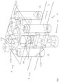
- Fig.1 shows an inspection device 1 which is arranged on a container transport device 2 belonging to a container treatment plant (not shown here).
- the container transport device 2 guides the containers 11 (see Fig. 2 ), in this case particularly transparent bottles, along a transport route through the container treatment plant.
- the transport direction is shown by an arrow.
- the inspection device 1 has five different control modules combined to form a structural unit.
- a first control module is designed to check a quality assurance element on a container closure (not shown here). This means that the control module can inspect a locking ring arranged on a container closure that is intended to be damaged when the container closure is opened.
- the first control module has two cameras 3.1, 3.2 for image capture.
- the cameras 3.1, 3.2 are arranged at a distance from one another, with the first camera 3.1 being arranged in the area of a container inlet 8 and vertically above the container transport device 2 in an area of an upper camera level 9.
- the second camera 3.2 of the first control module is also arranged in an area of the upper camera level 9 and vertically above the container transport device 2, but in the area of a container outlet 13 from the inspection device 1.
- Each camera 3.1, 3.2 has five beam deflection elements 3.1a -3.1e, 3.2a-3.2e.
- a triangular beam deflection element 3.1a, 3.2a with two mirror surfaces is arranged vertically below each camera 3.1, 3.2. Each of the mirror surfaces is in turn aligned with another mirror surface of an upper beam deflection element 3.1b, 3.1d, 3.2b, 3.2d.
- the mirror surfaces of the upper beam deflection elements 3.1b, 3.1d, 3.2b, 3.2d are in turn aligned with a lower beam deflection element 3.1d, 3.1e, 3.2d, 3.2e designed as a mirror. Consequently, the upper beam deflection elements 3.1a - 3.1c, 3.2a - 3.2c are arranged in an upper beam deflection plane arranged parallel to the transport device and the lower beam deflection elements 3.1d, 3.1e, 3.2d, 3.2e are arranged in a lower beam deflection plane.
- the lower beam deflection elements 3.1d, 3.1e, 3.2d, 3.2e are also set to an inspection position P (see Fig. 2 ) so that a container closure of a container (11) located in the inspection position P can be inspected via the beam deflection elements 3.1a-3.2e.
- a second control module also has a camera 4 for image capture arranged in the area of the upper camera level 9, which is designed to detect the position of a logo on the top of a container closure and is arranged vertically above the inspection position P, i.e. in extension of the longitudinal axis of the container (11). The second control module thus also detects the position of the logo as soon as the container 11 is in the inspection position P.
- a third control module like the first and second control modules, has a camera 5 arranged vertically above the container transport device 2 and in the upper camera plane 9, which is designed to determine the fill level in the container 11.
- the camera 5 and a beam deflection element 5a assigned to it are arranged in the region of a first side 12 of the transport path of the container transport device 2.
- a fourth control module also has a camera 6 arranged vertically above the container transport device 2 and in the upper camera plane 9, which is designed to determine a code position.
- the camera 6 of the fourth control module and a beam deflection element 6a assigned to it are also arranged in the area of the first side 12 of the transport path of the container transport device 2.
- the fifth control module is designed to detect the position of a label on the container 11 and has a camera 7 for image capture, which, together with a beam deflection element 7a assigned to it, is also arranged in the area of the first side 12 of the transport path.
- the camera 7 of the fifth control module is, however, arranged in a lower camera plane 15 that is displaced perpendicularly to the upper camera plane 9 in the direction of the container transport device 2.
- a ring lighting R is arranged adjacent to and below the upper camera level 9, which extends coaxially around a vertical longitudinal axis of the inspection position P.
- the ring lighting R illuminates in particular the closure logo on the container closure.
- a flat (rectangular) transmitted light illuminator D is arranged on the second side 14 of the transport path of the container transport device 2.
- the transmitted light illuminator D is used in particular for illuminating the (transparent) container (11) (bottle), for example when checking the tamper-evident element by means of the first control module or when detecting the filling quantity of the container (11) by means of the second control module.
- a lens (not shown here), in particular a film lens, can be arranged on the transmitted-light illuminator D, which aligns the light rays of the transmitted-light illuminator D in a specific spatial direction, for example in a spatial direction perpendicular to the surface of the transmitted-light illuminator D.
- a top-light illumination A is arranged, which is particularly suitable for better illumination of the side of the container 11 aligned with the first side 12 of the transport path. This can therefore be used, for example, to determine the position of the container label or to determine the code position.
- the top-light illumination A is arranged on the first side of the transport path and consists of two vertically spaced-apart light bodies that extend transversely to the longitudinal axis of the container.
- the top-light illumination A is arranged parallel to the transmitted-light illumination D.
- a container stream consisting of a plurality of containers 11, in this case filled transparent drinks bottles, is fed into the inspection device 1 by means of the transport device 2.
- the containers 11 were aligned in such a way that the label on the containers 11 points towards the first side 12 of the transport path.
- a further control module belonging to the structural unit can be provided for detecting the position of the container 11 and for positioning the container 11.
- control modules are activated one after the other in rapid succession.
- the respective lighting means D, A, R are activated in order to achieve particularly good illumination of the container 11 at the time of inspection.
- the transmitted light illuminator D and, if necessary, the ring light R are activated.
- the ring light R is activated, while when the control module is activated to determine the fill level, the transmitted light illuminator D is activated.
- the control modules are activated to determine a code position on the container 11 or to detect the position of the container label, the incident light A is activated.
- the lighting means for the control modules can also be switched in another way, provided that this results in better lighting of the container 11 during inspection by the respective control module. It is also possible, for example, to leave individual or multiple lighting means activated during the inspection of one or more control modules.
- control modules and the associated lighting devices A, D, R are activated is arbitrary. For example, it is also possible to activate one, two, three or four control modules at the same time. The only thing to note here is that, to ensure particularly good image capture quality, control modules/lighting units that behave in opposite ways should not be activated at the same time, but one after the other. For example, a control module that relies on a transparent light should not be activated if possible as soon as the incident light is activated.
- the container 11 is transported out of the inspection device 1 again by means of the transport device 2.
- the lighting units are designed to generate white light, for example. This particularly applies to the transmitted light lighting element D.
- the lighting elements A, R, D it is also possible to design one or more of the lighting elements A, R, D to generate a different type of light, for example infrared light.
Landscapes
- Engineering & Computer Science (AREA)
- General Physics & Mathematics (AREA)
- Physics & Mathematics (AREA)
- Theoretical Computer Science (AREA)
- Computer Vision & Pattern Recognition (AREA)
- Multimedia (AREA)
- Analytical Chemistry (AREA)
- General Health & Medical Sciences (AREA)
- Immunology (AREA)
- Pathology (AREA)
- Biochemistry (AREA)
- Chemical & Material Sciences (AREA)
- Life Sciences & Earth Sciences (AREA)
- Mechanical Engineering (AREA)
- Health & Medical Sciences (AREA)
- Signal Processing (AREA)
- Quality & Reliability (AREA)
- Investigating Materials By The Use Of Optical Means Adapted For Particular Applications (AREA)
Description
- Die Erfindung betrifft eine Behälterbehandlungsanlage mit einer Inspektionsvorrichtung zum Überprüfen von Behältern und einer Behältertransportvorrichtung zum Verlagern der Behälter in eine Inspektionsposition der Inspektionsvorrichtung.
- Beim Durchführen eines Behälters durch eine Behälterbehandlungsanlage mit unterschiedlichen Arbeitsstationen ist es üblich, verschiedene Merkmale des Behälters zu überprüfen. So können beispielsweise die Befüllmenge des Behälters, der Sitz eines Etikettes am Behälter oder auch die Position eines Behälterverschlusses bzw. eines Logos auf dem Behälterverschluss kontrolliert werden.
- Verschiedene Merkmale des Behälters müssen auch mehrfach während des Durchführens durch die Behälterbehandlungsanlage überprüft werden, um den Behälter beispielsweise vor einer Arbeitsstation in eine richtige Position zu bewegen. Auch können bei einer Endkontrolle des Behälters zahlreiche unterschiedliche Überprüfungsvorgänge durchgeführt bzw. wiederholt durchgeführt werden. Eine modular aufgebaute Inspektionsvorrichtung mit besonders einfach austauschbaren Kontrollstationen ist aus der
DE 10 2010 043 635 A1 bekannt. - Die zahlreichen einzelnen Kontrollstationen zum Durchführen der Prüfungsvorgänge nehmen bei den bekannten Vorrichtungen jedoch einen großen Bauraum in Anspruch. Auch muss der Behälterstrom an jeder einzelnen Kontrollstation wiederholt kurzzeitig gestoppt bzw. zumindest verlangsamt werden, wodurch die Durchlaufgeschwindigkeit des Behälters herabgesetzt wird.
- Aus Dokument
WO 2008/104273 A1 sind ein Verfahren und eine dazugehörige Inspektionsvorrichtung bekannt, mit der die Gesamttopographie eines Behälters erfasst wird. Der hieraus gebildete, einen dreidimensionalen Behälter darstellende Datensatz, der einen Ist-Zustand des Behälters abbildet, wird mit einem Soll-Zustand verglichen, um einzelne vom Soll-Zustand abweichende Merkmale zu ermitteln. - Dokument
EP 1 715 328 A1 dagegen offenbart eine Inspektionsvorrichtung, die eine verbesserte Aufnahme des Behälters in einer Einhausung ermöglicht. Hierfür offenbart dieEP 1 715 328 A1 eine spezielle Innenausgestaltung der Einhausung. Aus derWO 03/024859 A2 DE 10 2008 062 385 A1 offenbart eine Vorrichtung zur optischen Überprüfung eines Originalsicherungsringes an den Verschlüssen von Behältern. DieDE 10 2008 034 744 A1 beschreibt dagegen Kontrollvorrichtungen zum Ermitteln eines richtigen Etikettensitzes auf Behältern. -
EP 2 450 695 A1 offenbart eine Vorrichtung zum Inspizieren von Behältern mit einem Traggestell, an dem mehrere Kontrollmodule angeordnet werden können, die unterschiedliche Kontrollfunktionen haben, wie z.B. Behälterseitenwand, Verschluss oder Befüllzustand. Jedes Kontrollmodul stellt dabei eine eigene Einheit dar, die ein spezifisches Behältermerkmal kontrolliert. Die Kontrollmodule können an der Befestigungsvorrichtung des Traggestells nebeneinander, in beliebiger Position befestigt werden. Neben der eigentlichen Befestigungsvorrichtung können, bspw. besonders große Kontrollmodule auch seitlich am Traggestell montiert werden. Jedes Kontrollmodul agiert dabei eigenständig und erfasst den Behälter in jeweils einer dem einzelnen Kontrollmodul zugeordneten Inspektionsposition. - Der Erfindung liegt somit die Aufgabe zu Grunde, eine Behälterbehandlungsanlage mit einer zum Überprüfen einer Mehrzahl von Behältermerkmalen ausgebildeten besonders kompakten Inspektionsvorrichtung bereitzustellen, mit der eine auswählbare Anzahl von unterschiedlichen Behältermerkmalen ermittelt werden kann und die eine hohe Durchlaufgeschwindigkeit des Behälters ermöglicht.
- Die Erfindung löst die Aufgabe durch eine Behälterbehandlungsanlage mit den Merkmalen des Anspruchs 1. Vorteilhafte Weiterbildungen der Erfindung sind in den abhängigen Ansprüchen angegeben.
- Die erfinderische Behälterbehandlungsanlage weist eine Inspektionsvorrichtung zum Überprüfen von Behältern, insbesondere von Getränkebehältern, und eine Behältertransportvorrichtung zum Verlagern der Behälter in eine Inspektionsposition der Inspektionsvorrichtung auf, wobei die Inspektionsvorrichtung mindestens drei zu einer Baueinheit zusammengefasste Kontrollmodule aus der Gruppe:
- Kontrollmodul zum Überprüfen eines Originalitätssicherungselementes an einem Behälterverschluss,
- Kontrollmodul zur Feststellung einer Befüllmenge des Behälters,
- Kontrollmodul zur Lageerfassung eines Verschlusslogos an dem Behälterverschluss,
- Kontrollmodul zur Feststellung einer Codeposition am Behälter und/oder
- Kontrollmodul zur Lageerfassung eines Behälteretiketts aufweist, wobei der Behälter in der Inspektionsposition von mindestens zwei Kontrollmodulen erfassbar ist.
- Die Zusammenfassung von mindestens drei Kontrollmodulen zu einer Baueinheit ermöglicht eine besonders kompakte Ausbildung der Inspektionsvorrichtung. Hierdurch wird der notwendige Bauraum der Inspektionsvorrichtung deutlich verringert und die Inspektionsvorrichtung ist besonders einfach in die Behälterbehandlungsanlage und insbesondere in einen Behältertransportweg, d.h. entlang einer Transportstrecke des Behälters durch die Behälterbehandlungsanlage anordbar.
- Zudem ermöglicht die Inspektionsvorrichtung mit mindestens drei Kontrollmodulen eine besonders breite Einsatzmöglichkeit. So kann die Baueinheit an einer Vielzahl unterschiedlicher Positionen entlang der Transportstrecke angeordnet werden und ermöglicht auf einem besonders kurzen Streckenabschnitt der Transportstrecke eine Mehrzahl von Überprüfungsmöglichkeiten der Behältermerkmale.
- Bei den Behältern handelt es sich beispielsweise um Getränkebehälter. Dies können insbesondere Getränkeflaschen aus Kunststoff oder Glas sein, die beispielsweise zumindest teilweise transparent sind.
- Unter einer Behälterbehandlungsanlage kann eine einzelne Behälterbearbeitungsstation oder eine Vielzahl von Behälterbearbeitungsstationen, die der Behälter nacheinander durchläuft, verstanden werden. Die Behältertransportanlage ist dazu ausgelegt, den Behälter durch die Behälterbehandlungsanlage, d.h. durch oder an den einzelnen Stationen der Behälterbehandlungsanlage, vorbei zu führen. Hierfür weist die Behältertransportanlage insbesondere eine Vielzahl von Transporteuren zum linearen oder bogenförmigen Transport der Behälter oder auch Transportsterne zum Transport der Behälter auf einer Kreisbahn auf. Die Behältertransportvorrichtung transportiert folglich die Behälter entlang eines Behältertransportweges durch die Behälterbehandlungsanlage.
- Unter der Inspektionsposition wird die Position des Behälters verstanden, in der ein Kontrollmodul den Behälter inspizieren kann, d.h. beispielsweise ein Merkmal des Behälters überprüfen, erfassen oder auch feststellen kann. Unter den Merkmalen sind in diesem Zusammenhang insbesondere in den Behälter eingebrachte oder an den Behälter angebrachte Markierungen, Embossings, Codes, Etiketten oder Eigenschaften des Behälterkörpers an sich, jedoch auch Merkmale wie beispielsweise der Füllstand eines Behälters zu verstehen.
- Unter einem Kontrollmodul ist in diesem Zusammenhang eine Vorrichtung zu verstehen, die einen Ist-Zustand eines der Merkmale des Behälters inspiziert und diesen gegebenenfalls unter Zuhilfenahme einer Auswertungs- oder Steuerungseinheit mit einem Soll-Zustand vergleicht.
- Dabei sind die Kontrollmodule insbesondere zur optischen Erfassung, d.h. beispielsweise zur bildlichen Erfassung eines Merkmals, ausgebildet. Abhängig von den zu erfassenden Merkmalen kann das Kontrollmodul jedoch auch eine anderweitige Sensorik zum Inspizieren eines Merkmals aufweisen.
- Für eine besonders kompakte Ausbildung des Bauelementes und eine besonders vielseitige Einsatzmöglichkeit ist nach einer Weiterbildung der Erfindung vorgesehen, dass mindestens drei, bevorzugt mindestens vier oder besonders bevorzugt mindestens fünf Kontrollmodule zu einer Baueinheit zusammengefasst sind.
- Zum Inspizieren der Behälter durch die Kontrollmodule wird der Behälterstrom zumindest kurzfristig im Bereich der Inspektionsposition verlangsamt oder kurzzeitig gestoppt.
- Erfindungsgemäß ist der Behälter in der Inspektionsposition von mindestens drei Kontrollmodule, bevorzugt mindestens vier Kontrollmodulen, vorzugsweise mindestens fünf Kontrollmodulen erfassbar.
- Das Inspizieren des Behälters durch mehrere Kontrollmodule in einer einzigen Inspektionsposition ist besonders vorteilhaft, da die Durchlaufgeschwindigkeit der Behälter kaum verringert wird. Dabei kann das Inspizieren des Behälters beispielsweise von mehreren Kontrollmodulen gleichzeitig erfolgen. Auch können die einzelnen Kontrollmodule beispielsweise alle nacheinander den Inspektionsvorgang am Behälter durchführen.
- Üblicherweise werden die Behälter zum Inspizieren an den Kontrollmodulen vorbeigeführt. Um die zu einer Baueinheit zusammengefassten Kontrollmodule jedoch besonders kompakt zu gestalten, ist nach einer Weiterbildung der Erfindung vorgesehen, dass die Behältertransportvorrichtung einen durch die Inspektionsvorrichtung führenden Behältertransportweg aufweist, entlang dem der Behälter durch die Inspektionsvorrichtung transportiert wird. D.h., dass die Behälter durch die Inspektionsvorrichtung durchgeführt und somit entweder durch die Kontrollmodule hindurch und/oder an diesen entlanggeführt werden.
- Wie bereits oben erwähnt, sind die Kontrollmodule insbesondere zum optischen Inspizieren der Behälter ausgelegt. D.h., die Kontrollmodule können insbesondere ein Bild von dem Behälter bzw. eines Behälterabschnitts mit dem zu inspizierenden Merkmal erstellen. Um eine besonders hohe Genauigkeit des Kontrollmoduls bei der Inspektion des Behältermerkmals zu erreichen, ist nach einer Weiterbildung der Erfindung vorgesehen, dass die Inspektionsvorrichtung ein Beleuchtungsmittel, insbesondere eine Durchlichtbeleuchtung zum Durchleuchten des Behälters, eine Ringbeleuchtung und/oder eine Auflichtbeleuchtung zum Anleuchten des Behälters, aufweist.
- Das Beleuchtungsmittel kann derart angeordnet und ausgebildet sein, dass es für alle von der Baueinheit umfassten Kontrollmodule ausreichend Licht zur Verfügung stellt. Insbesondere bei der Anordnung unterschiedlicher Beleuchtungsmittel, wie einer Durchlichtbeleuchtung, einer Ringbeleuchtung oder einer Auflichtbeleuchtung, können die einzelnen Beleuchtungsmittel dazu ausgebildet sein, für ein oder mehrere Kontrollmodule eine besondere Lichtsituation bereitzustellen. Die Beleuchtungsmittel können daher separat voneinander angeordnet und separat steuerbar sein. Sie werden insbesondere im Zeitpunkt des Inspektionsvorgangs des jeweiligen Kontrollmoduls kurz aktiviert. Dabei ist es beispielsweise auch möglich, unterschiedliche Beleuchtungsmittel, wie beispielsweise die Ringbeleuchtung und die Auflichtbeleuchtung, gleichzeitig bei dem Inspektionsvorgang eines Kontrollmoduls oder mehrerer Kontrollmodule zu aktivieren. Folglich ist es ebenfalls möglich, die Beleuchtungsmittel derart anzusteuern, dass einzelne Beleuchtungsmittel während des Inspektionsvorgangs eines Kontrollmoduls nicht aktiviert sind, während andere Beleuchtungsmittel aktiviert sind.
- Um eine besonders gute Ausleuchtung des Behälters von seiner Oberseite zu erreichen, beispielsweise um eine Lageerfassung eines Verschlusslogos an einem Behälterverschluss zu verbessern, ist die Ringbeleuchtung besonders bevorzugt koaxial um eine Längsachse des Behälters in der Inspektionsposition angeordnet.
- Hierbei ist die Ringbeleuchtung insbesondere in einer Ebene oberhalb des Behälters angeordnet. Die Ringbeleuchtung ermöglicht somit eine von allen Seiten gleichmäßige Beleuchtung des Behälters bzw. zumindest eines oberen Behälterabschnitts, wie beispielsweise eines Flaschenhalses und/oder eines Behälterverschlusses.
- Um den Behälter von einer Seite besonders gleichmäßig auszuleuchten oder um insbesondere einen Behälterabschnitt, an dem beispielsweise ein Etikett angeordnet ist, einseitig besonders gut auszuleuchten, weist die Auflichtbeleuchtung besonders bevorzugt zwei im Abstand voneinander auf einer ersten Seite des Behältertransportweges angeordnete Leuchtkörper auf.
- Die Leuchtkörper sind dabei beispielsweise derart angeordnet, dass sie im Bereich eines Etikettes und hier insbesondere an einer Oberkante und an einer Unterkante eines Etikettes angeordnet sind. Dabei erstrecken sich die Leuchtkörper insbesondere quer zur Längsachse des Behälters, so dass gewährleistet ist, dass der Behälter zumindest von einer Seite (beispielsweise ein Umfang von 180°) vollständig beleuchtet wird.
- Nach einer Weiterbildung der Erfindung ist ferner vorgesehen, dass die Durchlichtbeleuchtung einen auf einer zweiten Seite des Behältertransportweges angeordneten flächigen Leuchtkörper aufweist.
- Um eine besonders gute Ausleuchtung des Behälters, beispielsweise zum Erfassen eines Durchlichtabbildes (wie eines Schattenbildes) des Behälters oder eines Behälterabschnittes zu ermöglichen, erstreckt sich der die Durchlichtbeleuchtung darstellende Leuchtkörper besonders in Längsachsenrichtung und quer zur Längsachsenrichtung des Behälters. Er kann beispielsweise als rechtwinkliger Leuchtkörper ausgebildet sein.
- Wie bereits oben erwähnt, erfolgt die Inspektion der Kontrollmodule insbesondere optisch. Um zudem beispielsweise die Inspektion des Behälters von mehreren Kontrollmodulen in einer einzelnen Inspektionsposition zu ermöglichen, ist nach einer Weiterbildung der Erfindung vorgesehen, dass mindestens ein Kontrollmodul mindestens eine Kamera und/oder mindestens ein Strahlenumlenkungselement zur optischen Überprüfung des Behälters aufweist.
- Die Strahlenumlenkungselemente ermöglichen dabei die Anordnung der Kamera in einer indirekten Position, d.h. in einer Position, in der das von der Kamera zu erfassende Merkmal nicht im direkten Erfassungsbereich der Kamera liegt, wenn der Behälter in der Inspektionsposition ist. Dementsprechend können abhängig von der Positionierung der Kamera auch mehrere zu einer Kamera gehörende Strahlenumlenkungselemente angeordnet sein.
- Beispielweise können bei einem Kontrollmodul zum Überprüfen des Originalitätssicherungselementes, das zum Erfassen eines 180°-Teilbereiches des Originalitätssicherungselementes ausgebildet ist, auf eine Kamera bis zu fünf Strahlenumlenkungselemente zugeordnet sein.
- Die Strahlenumlenkungselemente können beispielsweise als flächige Spiegel ausgebildet sein. Auch können die Strahlenumlenkungselemente Baukörper mit mehreren Spiegelflächen, insbesondere im Querschnitt dreieckig ausgebildete Baukörper sein. Auch können Strahlenumlenkungselemente als Prisma ausgebildet sein, die einen Lichtstrahl umlenken und/oder bündeln.
- Um eine besonders kompakte Ausführung der Baueinheit bereitzustellen, ist nach einer Weiterbildung der Erfindung vorgesehen, dass mindestens eine Kamera in einer oberhalb der Transportvorrichtung angeordneten oberen Kameraebene angeordnet ist. Alternativ oder ergänzend ist besonders bevorzugt mindestens eine Kamera in einer parallel zur oberen Kameraebene in Richtung auf die Transportvorrichtung verschobenen unteren Kameraebene angeordnet.
- In diesem Zusammenhang wird bei der Anordnung mehrerer Kameras unter einer Ebene verstanden, dass die Kameras einer Ebene weitestgehend den gleichen Abstand zur Transportebene aufweisen. D. h., die senkrechte Höhenposition der Kameras einer Ebene ist zumindest weitestgehend gleich.
- Um die Baueinheit besonders kompakt auszubilden und die Einsatzmöglichkeit der Baueinheit für besonders viele Merkmale des Behälters auszugestalten, ist nach einer Weiterbildung der Erfindung vorgesehen, dass
- das Kontrollmodul zum Überprüfen des Originalitätssicherungselementes in einem Einfahrbereich des Behälters in der Inspektionsvorrichtung und/oder in einem Ausfahrbereich des Behälters aus der Inspektionsvorrichtung mindestens eine Kamera und ein Strahlenumlenkungselement aufweist und/oder
- das Kontrollmodul zur Feststellung der Befüllmenge des Behälters und/oder das Kontrollmodul zur Feststellung der Codeposition am Behälter und/oder das Kontrollmodul zur Lageerfassung des Behälteretiketts auf der ersten Seite des Transportweges eine Kamera und ein Strahlenumlenkungselement aufweist, und/oder
- das Kontrollmodul zur Lageerfassung des Verschlusslogos an dem Behälterverschluss eine senkrecht über der Inspektionsposition angeordnete Kamera aufweist.
- Im Weiteren wird die Erfindung anhand eines Ausführungsbeispiels näher beschrieben. Es zeigt:
- Fig. 1
- schematisch in perspektivischer Darstellung eine an einer Behältertransportanlage angeordnete Inspektionsvorrichtung mit fünf zu einer Baueinheit zusammengefassten Kontrollmodulen;
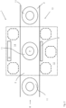
- Fig. 2
- schematisch in einem Querschnitt die Inspektionsvorrichtung aus
Fig. 1 . -
Fig. 1 zeigt eine Inspektionsvorrichtung 1, die an einer zu einer Behälterbehandlungsanlage (hier nicht dargestellt) gehörenden Behältertransportvorrichtung 2 angeordnet ist. Die Behältertransportvorrichtung 2 führt die Behälter 11 (sieheFig. 2 ), in diesem Fall insbesondere transparente Flaschen, entlang einer Transportstrecke durch die Behälterbehandlungsanlage durch. Die Transportrichtung ist durch einen Pfeil dargestellt. - Die Inspektionsvorrichtung 1 weist fünf verschiedene, zu einer Baueinheit zusammengefasste Kontrollmodule auf. Ein erstes Kontrollmodul ist zum Überprüfen eines Qualitätssicherungselementes an einem Behälterverschluss (hier nicht dargestellt) ausgebildet. D.h., das Kontrollmodul kann einen an einem Behälterverschluss angeordneten Sicherungsring inspizieren, der beim Öffnen des Behälterverschlusses beschädigt werden soll.
- Um den Sicherungsring, der den Flaschenhals vollständig umläuft, von allen Seiten (total side inspection) zu überprüfen, weist das erste Kontrollmodul zwei Kameras 3.1, 3.2 zur Bilderfassung auf. Die Kameras 3.1, 3.2 sind beabstandet voneinander angeordnet, wobei die erste Kamera 3.1 im Bereich eines Behältereinlaufs 8 und senkrecht über der Behältertransportvorrichtung 2 in einem Bereich einer oberen Kameraebene 9 angeordnet ist. Die zweite Kamera 3.2 des ersten Kontrollmoduls ist ebenfalls in einem Bereich der oberen Kameraebene 9 und senkrecht über der Behältertransportvorrichtung 2, jedoch im Bereich eines Behälterauslaufs 13 aus der Inspektionsvorrichtung 1, angeordnet.
- Zu jeder Kamera 3.1, 3.2 gehören fünf Strahlenumlenkungselemente 3.1a -3.1e, 3.2a-3.2e. Senkrecht unter jeder Kamera 3.1, 3.2 ist jeweils ein dreieckiges Strahlenumlenkungselement 3.1a, 3.2a mit zwei Spiegelflächen angeordnet. Jede der Spiegelflächen ist wiederum zu jeweils einer weiteren Spiegelfläche eines oberen Strahlenumlenkungselementes 3.1b, 3.1d, 3.2b, 3.2d ausgerichtet.
- Die Spiegelflächen der oberen Strahlenumlenkungselemente 3.1b, 3.1d, 3.2b, 3.2d sind wiederum zu jeweils einem als Spiegel ausgebildeten unterem Strahlenumlenkungselement 3.1d, 3.1e, 3.2d, 3.2e ausgerichtet. Folglich sind die oberen Strahlenumlenkungselemente 3.1a - 3.1c, 3.2a - 3.2c in einer zur Transportvorrichtung parallel angeordneten oberen Strahlenumlenkungsebene und die unteren Strahlenumlenkungselemente 3.1d, 3.1e, 3.2d, 3.2e in einer unteren Strahlenumlenkungsebene angeordnet.
- Die unteren Strahlenumlenkungselemente 3.1d, 3.1e, 3.2d, 3.2e sind zudem auf eine Inspektionsposition P (siehe
Fig. 2 ) ausgerichtet, so dass ein Behälterverschluss eines sich in der Inspektionsposition P befindenden Behälters (11) über die Strahlenumlenkungselemente 3.1a-3.2e überprüft werden kann. - Ein zweites Kontrollmodul weist ebenfalls eine im Bereich der oberen Kameraebene 9 angeordnete Kamera 4 zur Bilderfassung auf, die zur Lageerfassung eines Logos auf einer Behälterverschlussoberseite ausgebildet und senkrecht über der Inspektionsposition P, d.h. in Verlängerung der Längsachse des Behälters (11), angeordnet ist. Das zweite Kontrollmodul erfasst die Lage des Logos somit ebenfalls, sobald der Behälter 11 in der Inspektionsposition P ist.
- Ein drittes Kontrollmodul weist, wie das erste und zweite Kontrollmodul, eine senkrecht über der Behältertransportvorrichtung 2 und in der oberen Kameraebene 9 angeordnete Kamera 5 auf, die zum Feststellen der Füllmenge im Behälter 11 ausgebildet ist. Die Kamera 5 und ein ihr zugeordnetes Strahlenumlenkungselement 5a sind im Bereich einer ersten Seite 12 der Transportstrecke der Behältertransportvorrichtung 2 angeordnet.
- Ein viertes Kontrollmodul weist ebenfalls eine senkrecht über der Behältertransportvorrichtung 2 und in der oberen Kameraebene 9 angeordnete Kamera 6 auf, die zur Feststellung einer Codeposition ausgebildet ist. Entsprechend der Kamera 5 zum Feststellen der Füllmenge ist auch die Kamera 6 des vierten Kontrollmoduls und ein ihr zugeordnetes Strahlenumlenkungselement 6a im Bereich der ersten Seite 12 der Transportstrecke der Behältertransportvorrichtung 2 angeordnet.
- Das fünfte Kontrollmodul ist zur Lageerfassung eines Etiketts am Behälter 11 ausgebildet und weist eine Kamera 7 zur Bilderfassung auf, die zusammen mit einem ihr zugeordneten Strahlenumlenkungselement 7a ebenfalls im Bereich der ersten Seite 12 der Transportstrecke angeordnet ist. Die Kamera 7 des fünften Kontrollmoduls ist jedoch in einer zur oberen Kameraebene 9 senkrecht in Richtung der Behältertransportvorrichtung 2 verschobenen unteren Kameraebene 15 angeordnet.
- Um eine besonders gute Ausleuchtung des Behälters (11) in der Inspektionsposition beim Inspizieren zu erreichen, sind drei verschiedene Beleuchtungsmittel angeordnet.
Zum einen ist angrenzend und unterhalb der oberen Kameraebene 9 eine Ringbeleuchtung R angeordnet, die sich koaxial um eine senkrechte Längsachse der Inspektionsposition P erstreckt. Die Ringbeleuchtung R beleuchtet insbesondere das Verschlusslogo am Behälterverschluss. - Auf der zweiten Seite 14 der Transportstrecke der Behältertransportvorrichtung 2 ist ein flächiger (rechtwinkliger) Durchlichtbeleuchtungskörper D angeordnet. Der Durchlichtbeleuchtungskörper D dient insbesondere für eine Durchleuchtung des (transparenten) Behälters (11) (Flasche), beispielsweise bei der Überprüfung des Originalitätssicherungselementes, mittels des ersten Kontrollmoduls bzw. bei dem Erfassen der Befüllmenge des Behälters (11) mittels des zweiten Kontrollmoduls.
- Am Durchlichtbeleuchtungskörper D kann beispielsweise für eine besonders gute Ausleuchtung des Behälters 11 eine Linse (hier nicht dargestellt), insbesondere eine Folienlinse, angeordnet sein, die die Lichtstrahlen des Durchlichtbeleuchtungskörper D in eine bestimmte Raumrichtung, beispielsweise in eine Raumrichtung senkrecht zur Oberfläche des Durchlichtbeleuchtungskörper D, ausrichtet.
- Zusätzlich ist eine Auflichtbeleuchtung A angeordnet, die insbesondere zur besseren Ausleuchtung der zur ersten Seite 12 der Transportstrecke ausgerichteten Seite des Behälters 11 geeignet ist. Diese kann daher beispielsweise bei der Lageerfassung des Behälteretiketts oder auch zur Feststellung der Codeposition genutzt werden. Die Auflichtbeleuchtung A ist auf der ersten Seite der Transportstrecke angeordnet und besteht aus zwei senkrecht voneinander beabstandeten Leuchtkörpern, die sich quer zur Längsachse des Behälters erstrecken. Die Auflichtbeleuchtung A ist parallel zur Durchlichtbeleuchtung D angeordnet.
- Im Betrieb wird ein Behälterstrom aus einer Vielzahl von Behältern 11, in diesem Fall befüllte transparente Getränkeflaschen, mittels der Transportvorrichtung 2 in die Inspektionsvorrichtung 1 eingefahren. Die Behälter 11 wurden vor dem Einfahren derart ausgerichtet, dass das Etikett an den Behältern 11 in Richtung zur ersten Seite 12 der Transportstrecke zeigt. Alternativ kann beispielsweise auch ein weiteres zur Baueinheit gehörendes Kontrollmodul zur Lageerfassung des Behälters 11 und zur Positionierung des Behälters 11 vorgesehen sein.
- Sobald ein Behälter 11 sich in der Inspektionsposition P befindet, werden die Kontrollmodule in schneller Folge nacheinander aktiviert. Gleichzeitig mit den Kontrollmodulen werden die jeweiligen Beleuchtungsmittel D, A, R aktiviert, um eine besonders gute Ausleuchtung des Behälters 11 zum Zeitpunkt der Inspektion zu erreichen.
- So wird beispielsweise beim Aktivieren der Kameras 3.1, 3.2 zum Erfassen des Originalitätssicherungselementes, die Durchlichtbeleuchtungskörper D und gegebenenfalls zusätzlich die Ringbeleuchtung R aktiviert. Bei der Lageerfassung des Verschlusslogos wird beispielsweise die Ringbeleuchtung R aktiviert, während beim Aktivieren des Kontrollmoduls zur Feststellung der Füllmenge beispielsweise der Durchlichtbeleuchtungskörper D aktiviert wird. Letztlich wird beispielsweise mit der Aktivierung der Kontrollmodule zur Feststellung einer Codeposition am Behälter 11 bzw. zur Lageerfassung des Behälteretikettes die Auflichtbeleuchtung A aktiviert.
- Alternativ hierzu können die Beleuchtungsmittel zu den Kontrollmodulen auch anderweitig geschaltet werden, sofern hierdurch eine bessere Beleuchtung des Behälters 11 bei der Inspektion durch das jeweilige Kontrollmodul erreicht wird. Auch ist es beispielsweise möglich, einzelne oder mehrere Beleuchtungsmittel während der Inspektion eines Kontrollmoduls oder mehrerer Kontrollmodule aktiviert zu lassen.
- Die Reihenfolge der Aktivierung der Kontrollmodule und der dazugehörigen Beleuchtungsmittel A, D, R ist beliebig. So ist es beispielsweise alternativ auch möglich, ein, zwei, drei oder vier Kontrollmodule gleichzeitig miteinander zu aktivieren. Zu beachten ist hierbei ausschließlich, dass für eine besonders gute Qualität der Bilderfassung sich gegensätzlich verhaltende Kontrollmodule/Beleuchtungseinheiten nicht gleichzeitig, sondern nacheinander aktiviert werden sollten. So sollte z.B. ein Kontrollmodul, das auf eine Durchsichtbeleuchtung angewiesen ist, nach Möglichkeit nicht aktiviert werden, sobald die Auflichtbeleuchtung aktiviert wird.
- Nachdem alle notwendigen Kontrollmodule aktiviert wurden, wird der Behälter 11 mittels der Transportvorrichtung 2 wieder aus der Inspektionsvorrichtung 1 heraus transportiert.
- Grundsätzlich sind die Beleuchtungseinheiten beispielsweise zum Erzeugen von Weißlicht ausgebildet. Dies betrifft insbesondere das Durchlichtbeleuchtungselement D. Alternativ ist es beispielsweise auch möglich ein oder mehrere der Beleuchtungselemente A, R, D zum Erzeugen einer anderen Lichtart, beispielsweise eines Infrarotlichts, auszubilden.
-
- 1
- Inspektionsvorrichtung
- 2
- Behältertransportvorrichtung
- 3.1
- Kamera zur Bilderfassung
- 3.2
- Kamera zur Bilderfassung
- 3.1a - 3.2e
- Strahlenumlenkungselement
- 4
- Kamera zur Bilderfassung
- 4a
- Strahlenumlenkungselement
- 5
- Kamera zur Bilderfassung
- 5a
- Strahlenumlenkungselement
- 6
- Kamera zur Bilderfassung
- 6a
- Strahlenumlenkungselement
- 7
- Kamera zur Bilderfassung
- 7a
- Strahlenumlenkungselement
- 8
- Behältereinführungsbereich
- 9
- obere Kameraebene
- 10
- Baueinheit
- 11
- Behälter
- 12
- erste Seite einer Transportstrecke
- 13
- Behälterausführungsbereich
- 14
- zweite Seite einer Transportstrecke
- 15
- untere Kameraebene
- P
- Inspektionsposition
- A
- Auflichtbeleuchtung
- R
- Ringbeleuchtung
- D
- Durchlichtbeleuchtung
Claims (12)
- Behälterbehandlungsanlage mit- einer Inspektionsvorrichtung (1) zum Überprüfen von Behältern (11), insbesondere Getränkebehälter, und- einer Behältertransportvorrichtung (2) zum Verlagern der Behälter (11) in eine Inspektionsposition (P) der Inspektionsvorrichtung (1), wobei die Inspektionsvorrichtung (1) mindestens drei zu einer Baueinheit zusammengefasste Kontrollmodule aus der Gruppe:- Kontrollmodul zum Überprüfen eines Originalitätssicherungselementes an einem Behälterverschluss,- Kontrollmodul zur Feststellung einer Befüllmenge des Behälters (11),- Kontrollmodul zur Lageerfassung eines Verschlusslogos an dem Behälterverschluss,- Kontrollmodul zur Feststellung einer Codeposition am Behälter (11) und/oder- Kontrollmodul zur Lageerfassung eines Behälteretiketts aufweist, wobei der Behälter (11) in der einzigen Inspektionsposition (P) von mindestens zwei Kontrollmodulen erfassbar ist, wobei unter der Inspektionsposition eine Position des Behälters (11) verstanden wird, in der ein Kontrollmodul den Behälter (11) inspizieren, nämlich ein Merkmal des Behälters (11) überprüfen, erfassen oder auch feststellen kann, wobei jedes Kontrollmodul einen Ist-Zustand eines der Merkmale des Behälters (11) inspiziert und diesen unter Zuhilfenahme einer Auswertungs- oder Steuerungseinheit mit einem Soll-Zustand vergleicht.
- Behälterbehandlungsanlage nach Anspruch 1, dadurch gekennzeichnet, dass mindestens vier und bevorzugt mindestens fünf Kontrollmodule zu einer Baueinheit zusammengefasst sind.
- Behälterbehandlungsanlage nach Anspruch 1 oder 2, dadurch gekennzeichnet, dass der Behälter (11) in der Inspektionsposition (P) von mindestens drei Kontrollmodulen, bevorzugt mindestens vier Kontrollmodulen, vorzugsweise mindestens fünf Kontrollmodulen erfassbar ist.
- Behälterbehandlungsanlage nach einem der vorhergehenden Ansprüche, dadurch kennzeichnet, dass die Behältertransportvorrichtung (2) eine durch die Inspektionsvorrichtung (1) führende Behältertransportstrecke aufweist, entlang der die Behälter (11) durch die Inspektionsvorrichtung (1) transportierbar sind.
- Behälterbehandlungsanlage nach einem der vorhergehenden Ansprüche, dadurch gekennzeichnet, dass die Inspektionsvorrichtung (1) ein Beleuchtungsmittel, insbesondere eine Durchlichtbeleuchtung (D) zum Durchleuchten des Behälters (11), eine Ringbeleuchtung (R) und/oder eine Auflichtbeleuchtung (A) zum Anleuchten des Behälters (11), aufweist.
- Behälterbehandlungsanlage nach Anspruch 5, dadurch gekennzeichnet, dass die Ringbeleuchtung koaxial zu einer Längsachse des Behälters (11) in der Inspektionsposition (P) angeordnet ist.
- Behälterbehandlungsanlage nach Anspruch 5 oder 6, dadurch gekennzeichnet, dass die Auflichtbeleuchtung A zwei im Abstand voneinander auf einer ersten Seite (12) der Behältertransportstrecke angeordnete Leuchtkörper aufweist.
- Behälterbehandlungsanlage nach einem der Ansprüche 5 bis 7, dadurch gekennzeichnet, dass die Durchlichtbeleuchtung D einen auf einer der ersten Seite (12) gegenüberliegenden zweiten Seite (14) der Behältertransportstrecke angeordneten flächigen Leuchtkörper aufweist.
- Behälterbehandlungsanlage nach einem der vorhergehenden Ansprüche, dadurch gekennzeichnet, dass mindestens ein Kontrollmodul mindestens eine Kamera (3.1, 3.2, 4, 5, 6, 7) und/oder mindestens ein Strahlenumlenkungselement (3.1a-3.2e, 5a, 6a, 7a) zur optischen Überprüfung des Behälters (11) aufweist.
- Behälterbehandlungsanlage nach einem der vorhergehenden Ansprüche, dadurch gekennzeichnet, dass mindestens eine Kamera (3.1, 3.2, 4, 5, 6) in einer oberhalb der Behältertransportvorrichtung (2) angeordneten oberen Kameraebene (9) angeordnet ist.
- Behälterbehandlungsanlage nach einem der vorhergehenden Ansprüche, dadurch gekennzeichnet, dass mindestens eine Kamera (7) in einer parallel zur oberen Kameraebene (9) angeordneten in Richtung auf die Behältertransportvorrichtung (2) verschobenen unteren Kameraebene (15) angeordnet ist.
- Behälterbehandlungsanlage nach einem der vorhergehenden Ansprüche, dadurch gekennzeichnet, dass- das Kontrollmodul zum Überprüfen des Originalitätssicherungselementes in einem Einfahrbereich des Behälters (11) in der Inspektionsvorrichtung (1) und/oder in einem Ausfahrbereich des Behälters (11) aus der Inspektionsvorrichtung (1) mindestens eine Kamera (3.1, 3.2, 4, 5, 6, 7) und ein Strahlenumlenkungselement (3.1a-3.2e, 5a, 6a, 7a) aufweist und/oder- das Kontrollmodul zur Feststellung der Befüllmenge des Behälters (11) und/oder das Kontrollmodul zur Feststellung der Codeposition am Behälter (11) und/oder das Kontrollmodul zur Lageerfassung des Behälteretiketts auf der ersten Seite (12) des Transportweges eine Kamera (3.1, 3.2, 4, 5, 6, 7) und ein Strahlenumlenkungselement (3.1a-3.2e, 5a, 6a, 7a) aufweist, und/oder- das Kontrollmodul zur Lageerfassung des Verschlusslogos an dem Behälterverschluss eine senkrecht über der Inspektionsposition (P) angeordnet Kamera (3.1, 3.2, 4, 5, 6, 7) aufweist.
Applications Claiming Priority (2)
| Application Number | Priority Date | Filing Date | Title |
|---|---|---|---|
| DE102014102449.4A DE102014102449A1 (de) | 2014-02-25 | 2014-02-25 | Inspektionsvorrichtung |
| PCT/EP2015/053547 WO2015128245A1 (de) | 2014-02-25 | 2015-02-19 | Inspektionsvorrichtung |
Publications (3)
| Publication Number | Publication Date |
|---|---|
| EP3110701A1 EP3110701A1 (de) | 2017-01-04 |
| EP3110701B1 EP3110701B1 (de) | 2020-04-01 |
| EP3110701B2 true EP3110701B2 (de) | 2024-08-28 |
Family
ID=52589370
Family Applications (1)
| Application Number | Title | Priority Date | Filing Date |
|---|---|---|---|
| EP15706436.1A Active EP3110701B2 (de) | 2014-02-25 | 2015-02-19 | Behälterinspektionsvorrichtung |
Country Status (4)
| Country | Link |
|---|---|
| US (1) | US20170132776A1 (de) |
| EP (1) | EP3110701B2 (de) |
| DE (1) | DE102014102449A1 (de) |
| WO (1) | WO2015128245A1 (de) |
Families Citing this family (5)
| Publication number | Priority date | Publication date | Assignee | Title |
|---|---|---|---|---|
| EP3208782B1 (de) | 2016-02-22 | 2022-10-19 | Wincor Nixdorf International GmbH | Leergutrücknahmevorrichtung |
| CN112816718B (zh) * | 2019-11-15 | 2024-12-24 | 豪夫迈·罗氏有限公司 | 用于确定实验室样品容器性质的设备、方法和自动化系统 |
| CN113401458A (zh) * | 2021-05-28 | 2021-09-17 | 格力电器(郑州)有限公司 | 条码自动粘贴设备 |
| IT202100029912A1 (it) * | 2021-11-26 | 2023-05-26 | Gd Spa | Macchina per il riempimento e la chiusura di contenitori |
| DE102023132709A1 (de) * | 2023-11-23 | 2025-05-28 | Khs Gmbh | Verfahren zum Behandeln von Behältern und Anlage zum Behandeln von Behältern |
Citations (23)
| Publication number | Priority date | Publication date | Assignee | Title |
|---|---|---|---|---|
| GB2061491A (en) † | 1979-10-19 | 1981-05-13 | T I Fords Ltd | Bottle Inspection Method and Apparatus |
| EP0071068A1 (de) † | 1981-07-30 | 1983-02-09 | Alcoa Deutschland GmbH Maschinenbau | Einrichtung zum Sortieren von Behältern |
| US4713536A (en) † | 1985-12-30 | 1987-12-15 | Emhart Industries, Inc. | Molded code mark reader with elongated read beam |
| US4736851A (en) † | 1982-05-27 | 1988-04-12 | I2S | Process and apparatus for the automatic inspection by transparency contrast in particular of containers |
| US4816668A (en) † | 1985-12-30 | 1989-03-28 | Emhart Industries, Inc. | Mold number reader with field optics photodetector |
| EP0467211A2 (de) † | 1990-07-20 | 1992-01-22 | Westinghouse Electric Corporation | Schnell adaptierbares Ultraschallsystem zur Inspektion von Rohren mit verschiedenen Durchmessern |
| DE9311405U1 (de) † | 1993-07-30 | 1994-09-22 | Kronseder Maschf Krones | Inspektionsmaschine |
| JPH09169392A (ja) † | 1995-12-20 | 1997-06-30 | Mitsubishi Heavy Ind Ltd | 画像式打栓状態検査装置 |
| WO1998019150A2 (de) † | 1996-10-30 | 1998-05-07 | Krones Aktiengesellschaft Hermann Kronseder Maschinenfabrik | Inspektionsvorrichtung für flaschen oder dgl. |
| US5903341A (en) † | 1996-12-06 | 1999-05-11 | Ensco, Inc. | Produce grading and sorting system and method |
| DE10065290A1 (de) † | 2000-12-29 | 2002-07-11 | Krones Ag | Verfahren und Vorrichtung zur optischen Inspektion von Flaschen |
| US20030009984A1 (en) † | 2001-07-12 | 2003-01-16 | Zack Baskin | Lid placement and seating detector |
| DE10140009A1 (de) † | 2001-08-16 | 2003-03-13 | Krones Ag | Verfahren und Vorrichtung zur Inspektion gefüllter und verschlossener Flaschen |
| DE10146449A1 (de) † | 2001-09-20 | 2003-04-17 | Krones Ag | Verfahren zur Kontrolle von Verschlüssen auf Gefäßen |
| DE102007054657A1 (de) † | 2006-11-15 | 2008-07-03 | Loell Industry Solutions Gmbh | Optische Erfassungseinrichtung, insbesondere zur Inspektion von Flaschen, sowie entsprechendes Visualisierungsverfahren |
| US20080291438A1 (en) † | 2004-07-30 | 2008-11-27 | Eagle Vision Systems B.V. | Apparatus and Method for Checking of Containers |
| DE102008029661A1 (de) † | 2008-06-24 | 2009-12-31 | Khs Ag | Redundante Inspektion |
| DE102008053876A1 (de) † | 2008-10-30 | 2010-05-06 | Khs Ag | Flaschennaht- und Embossingausrichtung |
| DE102010004972A1 (de) † | 2010-01-18 | 2011-07-21 | Krones Ag, 93073 | Vorrichtung und Verfahren zum Inspizieren von Behältnissen |
| DE102010050673A1 (de) † | 2010-11-09 | 2012-05-10 | Krones Aktiengesellschaft | Vorrichtung und Verfahren zum Inspizieren von Behältnissen |
| WO2013013771A1 (de) † | 2011-07-28 | 2013-01-31 | Khs Gmbh | Inspektionseinheit |
| DE102012100987B3 (de) † | 2012-02-07 | 2013-07-11 | Miho Holding-Gmbh | Inspektionsvorrichtung und Inspektionsverfahren |
| DE102012009783B3 (de) † | 2012-05-18 | 2013-08-14 | Khs Gmbh | Verfahren und Vorrichtung zur Inspektion von Leerflaschen |
Family Cites Families (6)
| Publication number | Priority date | Publication date | Assignee | Title |
|---|---|---|---|---|
| DE102005017957A1 (de) | 2005-04-18 | 2006-10-26 | Khs Ag | Inspektionsvorrichtung |
| DE102007010018A1 (de) | 2007-03-01 | 2008-09-11 | Khs Ag | Verfahren und Inspektionsvorrichtung zur Untersuchung von Behältern |
| DE202008003953U1 (de) * | 2008-03-20 | 2008-07-10 | Pepperl + Fuchs Gmbh | Optischer Sensor |
| DE102008034744A1 (de) * | 2008-07-24 | 2010-01-28 | Khs Ag | Geblockte Inspektion |
| DE102008062385C5 (de) | 2008-12-17 | 2016-10-20 | Khs Gmbh | Verfahren sowie Inspektionsvorrichtung zum Überprüfen von Behältern |
| DE102010043635A1 (de) * | 2010-11-09 | 2012-05-10 | Krones Aktiengesellschaft | Vorrichtung zum Inspizieren von Behältern |
-
2014
- 2014-02-25 DE DE102014102449.4A patent/DE102014102449A1/de not_active Withdrawn
-
2015
- 2015-02-19 WO PCT/EP2015/053547 patent/WO2015128245A1/de not_active Ceased
- 2015-02-19 EP EP15706436.1A patent/EP3110701B2/de active Active
-
2016
- 2016-08-24 US US15/245,674 patent/US20170132776A1/en not_active Abandoned
Patent Citations (24)
| Publication number | Priority date | Publication date | Assignee | Title |
|---|---|---|---|---|
| GB2061491A (en) † | 1979-10-19 | 1981-05-13 | T I Fords Ltd | Bottle Inspection Method and Apparatus |
| EP0071068A1 (de) † | 1981-07-30 | 1983-02-09 | Alcoa Deutschland GmbH Maschinenbau | Einrichtung zum Sortieren von Behältern |
| US4736851A (en) † | 1982-05-27 | 1988-04-12 | I2S | Process and apparatus for the automatic inspection by transparency contrast in particular of containers |
| US4713536A (en) † | 1985-12-30 | 1987-12-15 | Emhart Industries, Inc. | Molded code mark reader with elongated read beam |
| US4816668A (en) † | 1985-12-30 | 1989-03-28 | Emhart Industries, Inc. | Mold number reader with field optics photodetector |
| EP0467211A2 (de) † | 1990-07-20 | 1992-01-22 | Westinghouse Electric Corporation | Schnell adaptierbares Ultraschallsystem zur Inspektion von Rohren mit verschiedenen Durchmessern |
| DE9311405U1 (de) † | 1993-07-30 | 1994-09-22 | Kronseder Maschf Krones | Inspektionsmaschine |
| JPH09169392A (ja) † | 1995-12-20 | 1997-06-30 | Mitsubishi Heavy Ind Ltd | 画像式打栓状態検査装置 |
| WO1998019150A2 (de) † | 1996-10-30 | 1998-05-07 | Krones Aktiengesellschaft Hermann Kronseder Maschinenfabrik | Inspektionsvorrichtung für flaschen oder dgl. |
| US5903341A (en) † | 1996-12-06 | 1999-05-11 | Ensco, Inc. | Produce grading and sorting system and method |
| DE10065290A1 (de) † | 2000-12-29 | 2002-07-11 | Krones Ag | Verfahren und Vorrichtung zur optischen Inspektion von Flaschen |
| US20030009984A1 (en) † | 2001-07-12 | 2003-01-16 | Zack Baskin | Lid placement and seating detector |
| DE10140009A1 (de) † | 2001-08-16 | 2003-03-13 | Krones Ag | Verfahren und Vorrichtung zur Inspektion gefüllter und verschlossener Flaschen |
| DE10140009B4 (de) † | 2001-08-16 | 2004-04-15 | Krones Ag | Vorrichtung zur Inspektion gefüllter und verschlossener Flaschen |
| DE10146449A1 (de) † | 2001-09-20 | 2003-04-17 | Krones Ag | Verfahren zur Kontrolle von Verschlüssen auf Gefäßen |
| US20080291438A1 (en) † | 2004-07-30 | 2008-11-27 | Eagle Vision Systems B.V. | Apparatus and Method for Checking of Containers |
| DE102007054657A1 (de) † | 2006-11-15 | 2008-07-03 | Loell Industry Solutions Gmbh | Optische Erfassungseinrichtung, insbesondere zur Inspektion von Flaschen, sowie entsprechendes Visualisierungsverfahren |
| DE102008029661A1 (de) † | 2008-06-24 | 2009-12-31 | Khs Ag | Redundante Inspektion |
| DE102008053876A1 (de) † | 2008-10-30 | 2010-05-06 | Khs Ag | Flaschennaht- und Embossingausrichtung |
| DE102010004972A1 (de) † | 2010-01-18 | 2011-07-21 | Krones Ag, 93073 | Vorrichtung und Verfahren zum Inspizieren von Behältnissen |
| DE102010050673A1 (de) † | 2010-11-09 | 2012-05-10 | Krones Aktiengesellschaft | Vorrichtung und Verfahren zum Inspizieren von Behältnissen |
| WO2013013771A1 (de) † | 2011-07-28 | 2013-01-31 | Khs Gmbh | Inspektionseinheit |
| DE102012100987B3 (de) † | 2012-02-07 | 2013-07-11 | Miho Holding-Gmbh | Inspektionsvorrichtung und Inspektionsverfahren |
| DE102012009783B3 (de) † | 2012-05-18 | 2013-08-14 | Khs Gmbh | Verfahren und Vorrichtung zur Inspektion von Leerflaschen |
Also Published As
| Publication number | Publication date |
|---|---|
| EP3110701A1 (de) | 2017-01-04 |
| US20170132776A1 (en) | 2017-05-11 |
| DE102014102449A1 (de) | 2015-08-27 |
| EP3110701B1 (de) | 2020-04-01 |
| WO2015128245A1 (de) | 2015-09-03 |
Similar Documents
| Publication | Publication Date | Title |
|---|---|---|
| EP2092311B1 (de) | Vorrichtung zur inspektion von flaschen oder dergleichen behältern | |
| EP3110701B2 (de) | Behälterinspektionsvorrichtung | |
| EP2450696B1 (de) | Vorrichtung und Verfahren zum Inspizieren von Behältnissen | |
| DE102010018823B4 (de) | Schwebstofferkennung in mit Flüssigkeit befüllten Behältnissen | |
| DE102010032166B4 (de) | Erfassungssystem und Inspektionsverfahren zur Flaschennaht- und Embossingausrichtung | |
| EP2112502B1 (de) | Verfahren und Vorrichtung zur Prüfung von Behälter-Preforms | |
| EP2369328B1 (de) | Vorrichtung und verfahren zum untersuchen von befüllten behältnissen auf fremdkörper | |
| DE102012009783B3 (de) | Verfahren und Vorrichtung zur Inspektion von Leerflaschen | |
| DE102010046461B4 (de) | Inspektionsverfahren, Inspektionsstation und Belichtungs- und Auswertevorrichtung | |
| DE102011004584A1 (de) | Verfahren und Vorrichtung zum Erkennen von Blasen und/oder Falten auf etikettierten Behältern | |
| EP3504538A1 (de) | Optisches inspektionssystem für preformlinge | |
| EP3152550B1 (de) | Inspektionsvorrichtung für behälterverschlüsse | |
| DE102016106266A1 (de) | Bereitstellen von vereinzelten Bauelementen mittels Vibration in einem Bereitstellungsbereich | |
| DE102010018824B4 (de) | Fremdstofferkennung in abgefüllten Flaschen | |
| EP2671649B1 (de) | Vorrichtung zur Identifizierung einer Flasche | |
| WO2009115169A1 (de) | Transportsystem für flaschen sowie vorrichtung zum behandeln von flaschen | |
| DE19852369C1 (de) | Vorrichtung und Verfahren zur Prüfung zylindrischer Prüflinge | |
| DE102018132132B3 (de) | Verfahren zur Erkennung eines Typs eines Behälters sowie Inspektionssystem | |
| DE102006048327A1 (de) | Verfahren und Vorrichtung zur optischen Erfassung von Fremdkörpern in mit Flüssigkeit gefüllten Flaschen | |
| DE102009036389A1 (de) | Verfahren und Vorrichtung zur Überprüfung von mit Gefäßen bestückten oder bestückbaren, oben offenen Aufnahmebehältern | |
| EP3165908B1 (de) | Vorrichtung zur inspektion mindestens eines druckbildes | |
| DE202020106449U1 (de) | Vorrichtung zum Inspizieren von Behältnissen | |
| DE20108131U1 (de) | Vorrichtung zur Erkennung des Materials von Gefäßen | |
| DE102014102450A1 (de) | Inspektionsvorrichtung mit inverser Folienlinse | |
| EP1577664B1 (de) | Inspektionsvorrichtung für flaschen oder dergleichen behälter |
Legal Events
| Date | Code | Title | Description |
|---|---|---|---|
| PUAI | Public reference made under article 153(3) epc to a published international application that has entered the european phase |
Free format text: ORIGINAL CODE: 0009012 |
|
| STAA | Information on the status of an ep patent application or granted ep patent |
Free format text: STATUS: REQUEST FOR EXAMINATION WAS MADE |
|
| 17P | Request for examination filed |
Effective date: 20160926 |
|
| AK | Designated contracting states |
Kind code of ref document: A1 Designated state(s): AL AT BE BG CH CY CZ DE DK EE ES FI FR GB GR HR HU IE IS IT LI LT LU LV MC MK MT NL NO PL PT RO RS SE SI SK SM TR |
|
| AX | Request for extension of the european patent |
Extension state: BA ME |
|
| DAX | Request for extension of the european patent (deleted) | ||
| STAA | Information on the status of an ep patent application or granted ep patent |
Free format text: STATUS: EXAMINATION IS IN PROGRESS |
|
| 17Q | First examination report despatched |
Effective date: 20171004 |
|
| RAP1 | Party data changed (applicant data changed or rights of an application transferred) |
Owner name: KHS GMBH |
|
| GRAP | Despatch of communication of intention to grant a patent |
Free format text: ORIGINAL CODE: EPIDOSNIGR1 |
|
| STAA | Information on the status of an ep patent application or granted ep patent |
Free format text: STATUS: GRANT OF PATENT IS INTENDED |
|
| INTG | Intention to grant announced |
Effective date: 20200108 |
|
| GRAS | Grant fee paid |
Free format text: ORIGINAL CODE: EPIDOSNIGR3 |
|
| GRAA | (expected) grant |
Free format text: ORIGINAL CODE: 0009210 |
|
| STAA | Information on the status of an ep patent application or granted ep patent |
Free format text: STATUS: THE PATENT HAS BEEN GRANTED |
|
| AK | Designated contracting states |
Kind code of ref document: B1 Designated state(s): AL AT BE BG CH CY CZ DE DK EE ES FI FR GB GR HR HU IE IS IT LI LT LU LV MC MK MT NL NO PL PT RO RS SE SI SK SM TR |
|
| REG | Reference to a national code |
Ref country code: GB Ref legal event code: FG4D Free format text: NOT ENGLISH |
|
| REG | Reference to a national code |
Ref country code: AT Ref legal event code: REF Ref document number: 1251064 Country of ref document: AT Kind code of ref document: T Effective date: 20200415 Ref country code: CH Ref legal event code: EP |
|
| REG | Reference to a national code |
Ref country code: DE Ref legal event code: R096 Ref document number: 502015012145 Country of ref document: DE |
|
| REG | Reference to a national code |
Ref country code: IE Ref legal event code: FG4D Free format text: LANGUAGE OF EP DOCUMENT: GERMAN |
|
| PG25 | Lapsed in a contracting state [announced via postgrant information from national office to epo] |
Ref country code: BG Free format text: LAPSE BECAUSE OF FAILURE TO SUBMIT A TRANSLATION OF THE DESCRIPTION OR TO PAY THE FEE WITHIN THE PRESCRIBED TIME-LIMIT Effective date: 20200701 |
|
| REG | Reference to a national code |
Ref country code: NL Ref legal event code: MP Effective date: 20200401 |
|
| REG | Reference to a national code |
Ref country code: LT Ref legal event code: MG4D |
|
| PG25 | Lapsed in a contracting state [announced via postgrant information from national office to epo] |
Ref country code: SE Free format text: LAPSE BECAUSE OF FAILURE TO SUBMIT A TRANSLATION OF THE DESCRIPTION OR TO PAY THE FEE WITHIN THE PRESCRIBED TIME-LIMIT Effective date: 20200401 Ref country code: NL Free format text: LAPSE BECAUSE OF FAILURE TO SUBMIT A TRANSLATION OF THE DESCRIPTION OR TO PAY THE FEE WITHIN THE PRESCRIBED TIME-LIMIT Effective date: 20200401 Ref country code: CZ Free format text: LAPSE BECAUSE OF FAILURE TO SUBMIT A TRANSLATION OF THE DESCRIPTION OR TO PAY THE FEE WITHIN THE PRESCRIBED TIME-LIMIT Effective date: 20200401 Ref country code: PT Free format text: LAPSE BECAUSE OF FAILURE TO SUBMIT A TRANSLATION OF THE DESCRIPTION OR TO PAY THE FEE WITHIN THE PRESCRIBED TIME-LIMIT Effective date: 20200817 Ref country code: LT Free format text: LAPSE BECAUSE OF FAILURE TO SUBMIT A TRANSLATION OF THE DESCRIPTION OR TO PAY THE FEE WITHIN THE PRESCRIBED TIME-LIMIT Effective date: 20200401 Ref country code: NO Free format text: LAPSE BECAUSE OF FAILURE TO SUBMIT A TRANSLATION OF THE DESCRIPTION OR TO PAY THE FEE WITHIN THE PRESCRIBED TIME-LIMIT Effective date: 20200701 Ref country code: GR Free format text: LAPSE BECAUSE OF FAILURE TO SUBMIT A TRANSLATION OF THE DESCRIPTION OR TO PAY THE FEE WITHIN THE PRESCRIBED TIME-LIMIT Effective date: 20200702 Ref country code: IS Free format text: LAPSE BECAUSE OF FAILURE TO SUBMIT A TRANSLATION OF THE DESCRIPTION OR TO PAY THE FEE WITHIN THE PRESCRIBED TIME-LIMIT Effective date: 20200801 Ref country code: FI Free format text: LAPSE BECAUSE OF FAILURE TO SUBMIT A TRANSLATION OF THE DESCRIPTION OR TO PAY THE FEE WITHIN THE PRESCRIBED TIME-LIMIT Effective date: 20200401 |
|
| PG25 | Lapsed in a contracting state [announced via postgrant information from national office to epo] |
Ref country code: RS Free format text: LAPSE BECAUSE OF FAILURE TO SUBMIT A TRANSLATION OF THE DESCRIPTION OR TO PAY THE FEE WITHIN THE PRESCRIBED TIME-LIMIT Effective date: 20200401 Ref country code: LV Free format text: LAPSE BECAUSE OF FAILURE TO SUBMIT A TRANSLATION OF THE DESCRIPTION OR TO PAY THE FEE WITHIN THE PRESCRIBED TIME-LIMIT Effective date: 20200401 Ref country code: HR Free format text: LAPSE BECAUSE OF FAILURE TO SUBMIT A TRANSLATION OF THE DESCRIPTION OR TO PAY THE FEE WITHIN THE PRESCRIBED TIME-LIMIT Effective date: 20200401 |
|
| REG | Reference to a national code |
Ref country code: DE Ref legal event code: R026 Ref document number: 502015012145 Country of ref document: DE |
|
| PLBI | Opposition filed |
Free format text: ORIGINAL CODE: 0009260 |
|
| PG25 | Lapsed in a contracting state [announced via postgrant information from national office to epo] |
Ref country code: AL Free format text: LAPSE BECAUSE OF FAILURE TO SUBMIT A TRANSLATION OF THE DESCRIPTION OR TO PAY THE FEE WITHIN THE PRESCRIBED TIME-LIMIT Effective date: 20200401 |
|
| PLAX | Notice of opposition and request to file observation + time limit sent |
Free format text: ORIGINAL CODE: EPIDOSNOBS2 |
|
| 26 | Opposition filed |
Opponent name: KRONES AG Effective date: 20201218 |
|
| PG25 | Lapsed in a contracting state [announced via postgrant information from national office to epo] |
Ref country code: SM Free format text: LAPSE BECAUSE OF FAILURE TO SUBMIT A TRANSLATION OF THE DESCRIPTION OR TO PAY THE FEE WITHIN THE PRESCRIBED TIME-LIMIT Effective date: 20200401 Ref country code: DK Free format text: LAPSE BECAUSE OF FAILURE TO SUBMIT A TRANSLATION OF THE DESCRIPTION OR TO PAY THE FEE WITHIN THE PRESCRIBED TIME-LIMIT Effective date: 20200401 Ref country code: EE Free format text: LAPSE BECAUSE OF FAILURE TO SUBMIT A TRANSLATION OF THE DESCRIPTION OR TO PAY THE FEE WITHIN THE PRESCRIBED TIME-LIMIT Effective date: 20200401 Ref country code: RO Free format text: LAPSE BECAUSE OF FAILURE TO SUBMIT A TRANSLATION OF THE DESCRIPTION OR TO PAY THE FEE WITHIN THE PRESCRIBED TIME-LIMIT Effective date: 20200401 Ref country code: ES Free format text: LAPSE BECAUSE OF FAILURE TO SUBMIT A TRANSLATION OF THE DESCRIPTION OR TO PAY THE FEE WITHIN THE PRESCRIBED TIME-LIMIT Effective date: 20200401 |
|
| PG25 | Lapsed in a contracting state [announced via postgrant information from national office to epo] |
Ref country code: SK Free format text: LAPSE BECAUSE OF FAILURE TO SUBMIT A TRANSLATION OF THE DESCRIPTION OR TO PAY THE FEE WITHIN THE PRESCRIBED TIME-LIMIT Effective date: 20200401 Ref country code: PL Free format text: LAPSE BECAUSE OF FAILURE TO SUBMIT A TRANSLATION OF THE DESCRIPTION OR TO PAY THE FEE WITHIN THE PRESCRIBED TIME-LIMIT Effective date: 20200401 |
|
| PLBB | Reply of patent proprietor to notice(s) of opposition received |
Free format text: ORIGINAL CODE: EPIDOSNOBS3 |
|
| PG25 | Lapsed in a contracting state [announced via postgrant information from national office to epo] |
Ref country code: SI Free format text: LAPSE BECAUSE OF FAILURE TO SUBMIT A TRANSLATION OF THE DESCRIPTION OR TO PAY THE FEE WITHIN THE PRESCRIBED TIME-LIMIT Effective date: 20200401 |
|
| PG25 | Lapsed in a contracting state [announced via postgrant information from national office to epo] |
Ref country code: MC Free format text: LAPSE BECAUSE OF FAILURE TO SUBMIT A TRANSLATION OF THE DESCRIPTION OR TO PAY THE FEE WITHIN THE PRESCRIBED TIME-LIMIT Effective date: 20200401 |
|
| GBPC | Gb: european patent ceased through non-payment of renewal fee |
Effective date: 20210219 |
|
| REG | Reference to a national code |
Ref country code: BE Ref legal event code: MM Effective date: 20210228 |
|
| PG25 | Lapsed in a contracting state [announced via postgrant information from national office to epo] |
Ref country code: LI Free format text: LAPSE BECAUSE OF NON-PAYMENT OF DUE FEES Effective date: 20210228 Ref country code: CH Free format text: LAPSE BECAUSE OF NON-PAYMENT OF DUE FEES Effective date: 20210228 Ref country code: LU Free format text: LAPSE BECAUSE OF NON-PAYMENT OF DUE FEES Effective date: 20210219 |
|
| PG25 | Lapsed in a contracting state [announced via postgrant information from national office to epo] |
Ref country code: GB Free format text: LAPSE BECAUSE OF NON-PAYMENT OF DUE FEES Effective date: 20210219 Ref country code: IE Free format text: LAPSE BECAUSE OF NON-PAYMENT OF DUE FEES Effective date: 20210219 |
|
| PG25 | Lapsed in a contracting state [announced via postgrant information from national office to epo] |
Ref country code: BE Free format text: LAPSE BECAUSE OF NON-PAYMENT OF DUE FEES Effective date: 20210228 |
|
| PGFP | Annual fee paid to national office [announced via postgrant information from national office to epo] |
Ref country code: AT Payment date: 20230217 Year of fee payment: 9 |
|
| PG25 | Lapsed in a contracting state [announced via postgrant information from national office to epo] |
Ref country code: HU Free format text: LAPSE BECAUSE OF FAILURE TO SUBMIT A TRANSLATION OF THE DESCRIPTION OR TO PAY THE FEE WITHIN THE PRESCRIBED TIME-LIMIT; INVALID AB INITIO Effective date: 20150219 |
|
| PG25 | Lapsed in a contracting state [announced via postgrant information from national office to epo] |
Ref country code: CY Free format text: LAPSE BECAUSE OF FAILURE TO SUBMIT A TRANSLATION OF THE DESCRIPTION OR TO PAY THE FEE WITHIN THE PRESCRIBED TIME-LIMIT Effective date: 20200401 |
|
| TPAC | Observations filed by third parties |
Free format text: ORIGINAL CODE: EPIDOSNTIPA |
|
| PG25 | Lapsed in a contracting state [announced via postgrant information from national office to epo] |
Ref country code: MK Free format text: LAPSE BECAUSE OF FAILURE TO SUBMIT A TRANSLATION OF THE DESCRIPTION OR TO PAY THE FEE WITHIN THE PRESCRIBED TIME-LIMIT Effective date: 20200401 |
|
| PUAH | Patent maintained in amended form |
Free format text: ORIGINAL CODE: 0009272 |
|
| STAA | Information on the status of an ep patent application or granted ep patent |
Free format text: STATUS: PATENT MAINTAINED AS AMENDED |
|
| 27A | Patent maintained in amended form |
Effective date: 20240828 |
|
| AK | Designated contracting states |
Kind code of ref document: B2 Designated state(s): AL AT BE BG CH CY CZ DE DK EE ES FI FR GB GR HR HU IE IS IT LI LT LU LV MC MK MT NL NO PL PT RO RS SE SI SK SM TR |
|
| REG | Reference to a national code |
Ref country code: DE Ref legal event code: R102 Ref document number: 502015012145 Country of ref document: DE |
|
| PG25 | Lapsed in a contracting state [announced via postgrant information from national office to epo] |
Ref country code: MT Free format text: LAPSE BECAUSE OF FAILURE TO SUBMIT A TRANSLATION OF THE DESCRIPTION OR TO PAY THE FEE WITHIN THE PRESCRIBED TIME-LIMIT Effective date: 20200401 |
|
| REG | Reference to a national code |
Ref country code: AT Ref legal event code: MM01 Ref document number: 1251064 Country of ref document: AT Kind code of ref document: T Effective date: 20240219 |
|
| PG25 | Lapsed in a contracting state [announced via postgrant information from national office to epo] |
Ref country code: AT Free format text: LAPSE BECAUSE OF NON-PAYMENT OF DUE FEES Effective date: 20240219 |
|
| PG25 | Lapsed in a contracting state [announced via postgrant information from national office to epo] |
Ref country code: AT Free format text: LAPSE BECAUSE OF NON-PAYMENT OF DUE FEES Effective date: 20240219 |
|
| PGFP | Annual fee paid to national office [announced via postgrant information from national office to epo] |
Ref country code: DE Payment date: 20250218 Year of fee payment: 11 |
|
| PGFP | Annual fee paid to national office [announced via postgrant information from national office to epo] |
Ref country code: FR Payment date: 20250221 Year of fee payment: 11 |
|
| PGFP | Annual fee paid to national office [announced via postgrant information from national office to epo] |
Ref country code: IT Payment date: 20250224 Year of fee payment: 11 |
|
| PG25 | Lapsed in a contracting state [announced via postgrant information from national office to epo] |
Ref country code: TR Free format text: LAPSE BECAUSE OF FAILURE TO SUBMIT A TRANSLATION OF THE DESCRIPTION OR TO PAY THE FEE WITHIN THE PRESCRIBED TIME-LIMIT Effective date: 20200401 |
|
| P01 | Opt-out of the competence of the unified patent court (upc) registered |
Free format text: CASE NUMBER: UPC_APP_0014575_3110701/2025 Effective date: 20251125 |