EP3109135B1 - Funktionsdurchbruch für freizeitfahrzeug oder reisemobil - Google Patents
Funktionsdurchbruch für freizeitfahrzeug oder reisemobil Download PDFInfo
- Publication number
- EP3109135B1 EP3109135B1 EP16167383.5A EP16167383A EP3109135B1 EP 3109135 B1 EP3109135 B1 EP 3109135B1 EP 16167383 A EP16167383 A EP 16167383A EP 3109135 B1 EP3109135 B1 EP 3109135B1
- Authority
- EP
- European Patent Office
- Prior art keywords
- vehicle
- pillar
- frame element
- opening
- box
- Prior art date
- Legal status (The legal status is an assumption and is not a legal conclusion. Google has not performed a legal analysis and makes no representation as to the accuracy of the status listed.)
- Active
Links
Images


Classifications
-
- B—PERFORMING OPERATIONS; TRANSPORTING
- B62—LAND VEHICLES FOR TRAVELLING OTHERWISE THAN ON RAILS
- B62D—MOTOR VEHICLES; TRAILERS
- B62D25/00—Superstructure or monocoque structure sub-units; Parts or details thereof not otherwise provided for
- B62D25/04—Door pillars ; windshield pillars
-
- B—PERFORMING OPERATIONS; TRANSPORTING
- B62—LAND VEHICLES FOR TRAVELLING OTHERWISE THAN ON RAILS
- B62D—MOTOR VEHICLES; TRAILERS
- B62D25/00—Superstructure or monocoque structure sub-units; Parts or details thereof not otherwise provided for
- B62D25/02—Side panels
Definitions
- the invention relates to a mobile home or box-shaped leisure vehicle, comprising a body substructure, a roof area, at least one vehicle wall with an inside and an outside and at least one C-vehicle pillar, the C-vehicle pillar being interrupted.
- the toilet which is usually designed to be transportable in such vehicles, can be removed or inserted from the correspondingly designed receptacle very laboriously and often in a cumbersome manner.
- the person skilled in the art is familiar with the fact that at least one tank or one functional volume is removed from an outside of the vehicle and inserted as well. Accordingly, an opening must be created in a vehicle wall through which the toilet or a tank can be inserted or removed.
- This opening must also be positioned and arranged in the vehicle wall in such a way that the usability of the toilet in the interior of the vehicle is ensured at least in this area.
- a vehicle pillar in particular a B-pillar of a motor vehicle, is already known, in which it is provided that the basic structure has at least two tube profiles connected to one another or is formed from them.
- DE 10 2007 039 315 A1 describes a transport vehicle in which the structure in the rear area has a lateral tapering section on the left and right side that is continuously bent inwards.
- a wall section for a vehicle is disclosed. From the DE 87 12 242 U1 you already know a caravan, mobile home or the like, in which a rounding parallel to a plane spanned by the direction of travel and the vertical plane between two body walls achieved through a bow connector. Furthermore, from the U.S. 7,581,782 B2 known an opening in a vehicle pillar with a seat for the belt reel.
- the object of the invention is therefore to improve the possible uses of mobile homes or box-shaped leisure vehicles with regard to their limited spatial conditions, in particular the interior.
- a mobile home or box-shaped leisure vehicle comprising a body substructure, a roof area, at least one vehicle wall with an inside (IS) and an outside (AS) and at least one C-vehicle pillar, the C-vehicle pillar having a support profile with at least comprises two outer edges and at least one connection section, the at least two outer edges being connected to one another via at least one profile section, the at least two outer edges being arranged with a lower end and an upper end between the body substructure and the roof area and the at least one connection section is connected to the body substructure and/or the roof area and/or the at least one vehicle wall, characterized in that the C vehicle pillar is interrupted at least in sections along at least one outer edge, with at least one frame element at least in a partial area of the interrupted C vehicle pillar and/or at least one frame element is connected to the body substructure and at least a partial area of the C-vehicle pillar and/or to a wheel housing, the at least one vehicle wall having at
- the interrupted area of the connecting element can be used as storage space. It is also conceivable to use the space gained by means of the interrupted connecting element for an opening to the outside, in particular a flap or the like.
- At least one frame element is arranged at least in a partial area of the interrupted connecting element and/or at least one frame element is connected to the body substructure and at least a partial area of the connecting element and/or to a wheel housing, with the at least one vehicle wall having at least one opening , which is arranged at least partially in the region of at least one interrupted outer edge and wherein an opening of at least one frame element arranged predominantly on the inside and at least one opening in the vehicle wall are aligned with one another.
- the opening in the vehicle wall is thus located in an area of the outer edge or in an area of the connecting element.
- the opening can be arranged anywhere in the vehicle wall. This allows a very special degree of increased flexibility with regard to the construction of mobile homes or box-shaped leisure vehicles.
- a frame element enables the interrupted connection element to be stabilized.
- the at least one outer edge has at least one interruption in a region of the body substructure.
- a further embodiment of the invention provides that the connecting element Support profile comprising two outer edges, both outer edges are interrupted and / or at least one outer edge has at least two interruptions.
- the connecting element is completely interrupted along its longitudinal extension (L) in at least two different areas oriented in the transverse extension (Q).
- Such a frame element enables the interrupted connection element to be stabilized.
- the connecting element can be interrupted between the body substructure and the roof area in such a way that in the remaining area it is connected both to the roof area and to the body substructure.
- the frame element pre-round and/or in one piece.
- a frame element can be produced inexpensively with little effort.
- a one-piece frame element can be designed as a folded sheet metal element or profile, which can be easily produced over a large area and shaped by means of folding or bending mechanics.
- the frame element is connected at least to the vehicle wall, the body substructure or the connecting element by means of at least one connecting element.
- box-shaped frame element is connected at least to the body substructure or the connecting element by means of an adhesive and/or screw connection.
- This provides a way of fastening the frame element that can be carried out easily and cost-effectively and entails only a few equipment requirements.
- An embodiment of the invention can provide that a frame element is connected in a flange-like manner to the inside and to the outside of the vehicle wall.
- a further embodiment of the invention can provide that at least the outside of the vehicle wall comprises an opening opposite the frame element.
- the method can provide that at least one device for opening and closing is attached in the area of the vehicle wall in such a way that the device covers a major area of the opening.
- FIG. 1 A portion of a motorhome or box-type recreational vehicle 1 as known in the prior art is shown.
- the mobile home or box-shaped leisure vehicle 1 has a body substructure 2 , a roof area 3 and a vehicle wall 4 .
- the section shown here relates to the usable area, which for the most part faces away from the cockpit or the front of the mobile home or box-shaped leisure vehicle 1 .
- the vehicle wall 4 is connected to the roof area 3 and the body substructure 2 .
- One such a connection can be made, for example, by means of an adhesive. However, it is also conceivable to realize the connection without using adhesives and for example by using screws, rivets, etc.
- connecting elements 5 are provided to stabilize it and thus the entire motor home or box-shaped leisure vehicle 1 .
- vehicle pillar is usually used synonymously with the term connecting element 5 .
- the vehicle pillars which to a certain extent represent load-bearing elements or significantly influence the statics of a vehicle, starting from the front with the letters A, B, C, etc.
- the terms A, B, C, D, etc. pillar can thus be used, which are to be equated with the term connecting element 5.
- the term connecting element 5 refers to a vertical alignment, corresponding to this arrangement of known vehicle columns. That in the figure 1 Connecting element 5 shown can be equated with a so-called C-pillar.
- the connecting element 5 is connected to the body substructure 2 via a corner profile 13 . Furthermore, the corner profile 13 is connected to the wheel housing 12 . As a rule, the vehicle wall 4 is stabilized in this way.
- FIG 2 a schematic representation of a section of a mobile home or box-shaped leisure vehicle 1 according to the invention is shown.
- the mobile home or box-shaped leisure vehicle 1 according to the invention has a body substructure 2 , a roof area, a corner profile 13 and a wheel housing 12 .
- the motorhome or boxy Recreational vehicle also a vehicle wall 4.
- the connecting element 5 is no longer arranged continuously between the body substructure 2 and the roof area 3. Rather, a piece of the connecting element 5 is removed. In other words, the connecting element 5 is interrupted in sections.
- the connecting element 5 is interrupted in the area of the body substructure 2 or in the area of the roof area 3 . It is also possible for the connecting element to be interrupted approximately in the middle in relation to the body substructure 2 and the roof area 3 .
- connecting element 5 Due to the fact that the connecting element 5 is connected to the inside IS of the vehicle wall 4 despite the interruption shown or despite the part that has been cut out, it is also possible for the connecting element 5 to be interrupted several times.
- An opening 14 in the vehicle wall 4 is also sketched in dashed lines.
- a toilet or a tank (not shown in detail) can be inserted or removed from the mobile home or box-shaped leisure vehicle 1 through this opening 14 .
- the opening 14 can now be arranged in an additional area of the vehicle wall 4 that was previously inaccessible for openings. This enables completely new perspectives in the interior design or in the possible uses of such motorhomes or box-shaped leisure vehicles 1.
- in the area of the opening 14 on the inside IS of the vehicle wall 4 or in the interior IR of the motorhome or box-shaped leisure vehicle 1 Sanitary area to be arranged. This would allow an interior IR of the mobile home or box-shaped leisure vehicle, for example from such a sanitary room, through the interrupted connecting element 5 practically through an opening 14 in the vehicle wall 4 with an outer area of the Motorhomes or box-shaped recreational vehicle 1 to connect.
- An opening or closing device e.g. a flap, is provided for the opening 14 in a manner that is not shown in detail.
- this opening or closing device can be arranged on the outside AS of the vehicle wall 4 or on the inside IS of the vehicle wall 4 . It is also possible that two opening and closing devices are provided, one on the inside IS and one on the outside AS of the vehicle wall 4 of the mobile home or box-shaped leisure vehicle 1 .
- FIG 3 is a schematic representation of a further embodiment of a section of a mobile home or box-shaped leisure vehicle 1 according to the invention, which also includes a body substructure 2, a roof area 3, a vehicle wall 4, a wheel housing 12 and a corner profile 13.
- the mobile home or box-shaped leisure vehicle 1 also includes a connecting element 5. In the exemplary embodiment shown, this is connected to the roof area 3 and the vehicle wall 4 and interrupted.
- a frame element 9 is arranged between the body substructure 2 and the roof area 3 .
- a section of the connecting element 5 has been removed and replaced by the frame element 9 .
- the frame element 9 serves to stabilize the area that was created by the interrupted connecting element 5 .
- the frame element is non-round, essentially rectangular.
- the frame element 9 is also designed in one piece, e.g. formed as a folded sheet metal element.
- the frame element 9 is polygonal is designed. Furthermore, it is possible for the frame element 8 to be designed in several parts.
- the frame element 9 has an opening 15 .
- the frame element can also have a plurality of openings in a manner that is not shown in detail.
- the frame element 9 can be connected to the connecting element 5 as well as to the body substructure 2, to the corner profile 13 or to the wheel housing 12. Combinations thereof are also conceivable.
- the frame element 9 has an opening 15 .
- This opening 15 is essentially congruent with the opening 14 of the vehicle wall 4. This creates a connection between the outside of the motor home or box-shaped leisure vehicle 1 and its interior IR, with the connection taking place through the interrupted connecting element 5 and the frame element 9. It is thus possible to insert or remove an object, for example a portable toilet or a tank, from the outside into the inside of the mobile home or box-shaped leisure vehicle 1 .
- the two openings 14 and 15 do not fit exactly or are congruent.
- the openings 14, 15 have different sizes.
- the frame element 9 is arranged in the vehicle wall 4 in such a way that it is arranged on the inside IS and the outside AS of the vehicle wall 4 .
- the frame element 9 is arranged in a flange-like manner on the inside IS of the vehicle wall 4 and/or the outside AS of the vehicle wall 4 .
- the frame element 9 can be used as a plug-in element with a collar from the outside be inserted into the opening 14 in order in this way to provide a sustainable connection to the vehicle wall 4 and the remaining sections of the connecting element 5 .
- the frame element 9 may be arranged flush on the outside AS of the vehicle wall 4 .
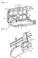
- the figure 4 shows a detailed view, in which in particular the connecting element 5 and the frame element 9 are emphasized. It can be seen here that the frame element 9 is connected to the connecting element 5 and to the body substructure 2 by means of connecting means 10, 10a.
- the frame element 9 it is also possible for the frame element 9 to be connected to the connecting element 5, the wheel housing 12 or the corner profile 13 by means of only one connecting means 10, 10a.
- connecting means 10, 10a are connected to the frame element 9, the wheel housing 12 or the corner profile 13.
- a plurality of frame elements 9 to be arranged between the body substructure 2 and the roof area 3 , with the arrangement taking place at least partially in the area of the connecting element 5 .
- the vehicle wall 4 has a plurality of openings 14 and thus multiple connections are created between the outside AS of the vehicle wall 4 and the inside IS of the vehicle wall 4 .
- the frame element is 9 arranged flush to the body substructure.
- the frame element 9 it is also conceivable for the frame element 9 not to be arranged flush with the body substructure 2 .
- FIG 5 is a section along line AA in 4 shown.
- the frame element 9 is schematically provided here as a profile with a right-hand outer edge 8a, a left-hand outer edge 8b and a connecting edge 8c.
- the frame element 9 is connected to the vehicle wall 4 in a known manner (point, rivet, adhesive connection, etc.).
- the arrangement of the frame element 9 is on the inside IS of the vehicle wall 4, opposite the outside AS.
- a support profile 6 and a profile section 11 are also shown.
Landscapes
- Engineering & Computer Science (AREA)
- Chemical & Material Sciences (AREA)
- Combustion & Propulsion (AREA)
- Transportation (AREA)
- Mechanical Engineering (AREA)
- Body Structure For Vehicles (AREA)
Description
- Die Erfindung betrifft ein Reisemobil oder kastenförmiges Freizeitfahrzeug, umfassend einen Karosserieunterbau, einen Dachbereich, wenigstens eine Fahrzeugwand mit einer Innenseite und einer Außenseite und wenigstens eine C-Fahrzeugsäule, wobei die C-Fahrzeugsäule unterbrochen ist.
- Reisemobile oder kastenförmige Freizeitfahrzeuge sind den einschlägigen Fachkreisen seit geraumer Zeit hinlänglich bekannt.
- Es ist im Zusammenhang mit eben bekannten Reisemobilen oder kastenförmigen Freizeitfahrzeugen ebenso seit jeher von großer Problematik, dass der zur Verfügung stehende Platz bzw. Raum im Inneren solcher Fahrzeuge oft nur sehr begrenzt ist. Gleichzeitig sind jedoch die Anforderungen an die Nutzung solcher Fahrzeuge sehr hoch, insbesondere im Hinblick auf die Nutzbarkeit des Innenraumes. Beispielsweise sollen solche Fahrzeuge bei Benutzung einen sehr hohen Wohnstandard nachstellen und beispielsweise Küche, Sanitär, Schlaf- und Aufenthaltsräume sowie ggf. weitere Nutzräume bereitstellen. Dies bedeutet für die Gestaltung bzw. Konstruktion solcher Reisemobile oder kastenförmiger Freizeitfahrzeuge eine große Herausforderung.
- Beispielsweise besteht hinsichtlich der Toilette und insbesondere hinsichtlich deren Ein- und Ausbau eine erhöhte Problematik, die sich aus den beengten Platzbedingungen solcher Fahrzeuge ergibt. Es ist bei gewissen Baureihen von Reisemobilen oder Freizeitfahrzeugen beispielsweise bekannt, dass die Toilette, die in solchen Fahrzeugen üblicherweise transportabel ausgestaltet ist, sehr mühselig und oftmals umständlich der entsprechend ausgestalteten Aufnahme entnommen bzw. eingesetzt werden kann. Dem Fachmann ist hierzu geläufig, dass die Entnahme zumindest eines Tanks oder eines Funktionsvolumens von einer Außenseite des Fahrzeugs erfolgt und ein Einführen ebenso. Es ist dementsprechend eine Öffnung in einer Fahrzeugwand zu schaffen, durch welche die Toilette oder ein Tank ein- bzw. ausgeführt werden kann. Diese Öffnung muss zudem so in der Fahrzeugwand positioniert und angeordnet sein, dass zumindest in diesem Bereich auch die Nutzbarkeit der Toilette im Innenraum des Fahrzeugs sichergestellt ist. Dies bedeutet bei heutigem Standard, dass im Bereich der Öffnung in der Fahrzeugwand ein Sanitärbereich angeordnet ist.
- Um auch weitere Räume zu schaffen, ist somit eine komplexe Raumgestaltung von Nöten. Oftmals lassen sich diesbezüglich viele verschiedene Aspekte konstruktiv nicht miteinander vereinen, woraus resultiert, dass Nutzungsmöglichkeiten solcher Fahrzeuge hinsichtlich ihrer begrenzten räumlichen Verhältnisse, insbesondere des Innenraumes begrenzt sind. Flexibilitäten bei der Positionierung und der Raumplanung werden dadurch eingeschränkt.
- Aus dem Stand der Technik der
DE 10 2013 002 306 A1 kennt man bereits eine Fahrzeugsäule, insbesondere B-Säule eines Kraftfahrzeugs, bei der vorgesehen ist, dass die Grundstruktur wenigstens zwei miteinander verbundene Rohrprofile aufweist oder daraus gebildet ist. In derDE 10 2007 039 315 A1 ist ein Transport-Fahrzeug beschrieben, bei dem der Aufbau im Heckbereich links- und rechtsseitig jeweils einen stetig nach innen gebogenen seitlichen Verjüngungsabschnitt aufweist. In derUS 2015/0001883 A1 ist ein Wandabschnitt für ein Fahrzeug offenbart. Aus derDE 87 12 242 U1 kennt man bereits einen Wohnwagen, Campingmobil oder dergleichen, bei welchem eine Abrundung parallel zu einer von der Fahrtrichtung und der Vertikalen aufgespannten Ebene zwischen zwei Aufbauwänden durch ein Bogen-Verbindungsstück erzielt wird. Weiterhin ist aus derUS 7 581 782 B2 eine Öffnung in einer Fahrzeugsäule mit Aufnahme für die Gurtspule bekannt. - Aufgabe der Erfindung ist es somit, die Nutzungsmöglichkeiten von Reisemobilen oder kastenförmigen Freizeitfahrzeugen hinsichtlich ihrer begrenzten räumlichen Verhältnisse, insbesondere des Innenraumes, zu verbessern.
- Zur Lösung der Aufgabe wird ein Reisemobil oder kastenförmiges Freizeitfahrzeug vorgeschlagen, umfassend einen Karosserieunterbau, einen Dachbereich, wenigstens eine Fahrzeugwand mit einer Innenseite (IS) und einer Außenseite (AS) und wenigstens einer C-Fahrzeugsäule, wobei die C-Fahrzeugsäule ein Tragprofil mit wenigstens zwei Außenkanten und mindestens einen Anbindungsabschnitt umfasst, wobei die wenigstens zwei Außenkanten über mindestens einen Profilabschnitt miteinander verbunden sind, wobei die wenigstens zwei Außenkanten mit einem unteren Ende und einem oberen Ende zwischen Karosserieunterbau und Dachbereich angeordnet sind und wobei der
mindestens eine Anbindungsabschnitt mit dem Karosserieunterbau und/oder dem Dachbereich und/oder der wenigstens einen Fahrzeugwand verbunden ist, dadurch gekennzeichnet, dass die C-Fahrzeugsäule wenigstens abschnittsweise entlang wenigstens einer Außenkante unterbrochen ist, wobei wenigstens ein Rahmenelement zumindest in einem Teilbereich der unterbrochenen C-Fahrzeugsäule angeordnet ist und/oder wenigstens ein Rahmenelement mit dem Karosserieunterbau und zumindest einem Teilbereich der C-Fahrzeugsäule und/oder mit einem Radkasten verbunden ist, wobei die wenigstens eine Fahrzeugwand zumindest eine Öffnung aufweist, welche zumindest teilweise im Bereich wenigstens einer unterbrochenen Außenkante angeordnet ist und wobei eine Öffnung wenigstens eines überwiegend auf der Innenseite (IS) angeordneten Rahmenelements und wenigstens eine Öffnung in der Fahrzeugwand aufeinander ausgerichtet sind. - Beispielsweise kann der unterbrochene Bereich des Verbindungselements als Stauraum verwendet werden. Denkbar ist weiterhin, den Platz- bzw. Raumgewinn, der mittels des unterbrochenen Verbindungselements geschaffen wird, für einen Durchbruch nach Außen, insbesondere eine Klappe oder dergleichen zu nutzen.
- Erfindungsgemäß ist vorgesehen, dass wenigstens ein Rahmenelement zumindest in einem Teilbereich des unterbrochenen Verbindungselements angeordnet ist und/oder wenigstens ein Rahmenelement mit dem Karosserieunterbau und zumindest einem Teilbereich des Verbindungselementes und/oder mit einem Radkasten verbunden ist, wobei die wenigstens eine Fahrzeugwand zumindest eine Öffnung aufweist, welche zumindest teilweise im Bereich wenigstens einer unterbrochenen Außenkante angeordnet ist und wobei eine Öffnung wenigstens eines überwiegend auf der Innenseite angeordneten Rahmenelements und wenigstens eine Öffnung in der Fahrzeugwand aufeinander ausgerichtet sind.
- Die Öffnung in der Fahrzeugwand befindet sich somit in einem Bereich der Außenkante bzw. in einem Bereich des Verbindungselements. Dadurch kann die Öffnung beliebig in der Fahrzeugwand angeordnet werden. Dies ermöglicht in ganz besonderem Maße eine erhöhte Flexibilität bezüglich der Konstruktion von Reisemobilen oder kastenförmigen Freizeitfahrzeugen. Ein Rahmenelement ermöglicht eine Stabilisierung des unterbrochenen Verbindungselements.
- Erfindungsgemäss ist vorgesehen, dass die wenigstens eine Außenkante in einem Bereich des Karosserieunterbaus zumindest eine Unterbrechung aufweist.
- Eine derart angeordnete Unterbrechung ermöglicht somit eine Nutzbarkeit im bodennahen Bereich des Reisemobiles oder kastenförmigen Freizeitfahrzeuges. Eine weitere Ausgestaltung der Erfindung sieht vor, dass das Verbindungselement ein Tragprofil mit zwei Außenkanten umfasst, wobei beide Außenkanten unterbrochen sind und/oder wenigstens eine Außenkante zumindest zwei Unterbrechungen aufweist.
- In einer weiteren Ausgestaltung der Erfindung kann vorgesehen sein, dass das Verbindungselement entlang seiner Längserstreckung (L) an wenigstens zwei verschiedenen in Quererstreckung (Q) orientieren Bereichen vollständig unterbrochen ist.
- Aus einem derart unterbrochenen Verbindungselement, das in anderen Worten abschnittsweise entfernt wird, folgt, dass ein entsprechend der Größe des entfernten Abschnitts des Verbindungselements gebildetes Volumen bzw. Platz geschaffen wird.
- Ein solches Rahmenelement ermöglicht eine Stabilisierung des unterbrochenen Verbindungselements.
- Das Verbindungselement kann zwischen dem Karosserieunterbau und dem Dachbereich derart unterbrochen werden, dass es im verbliebenen Bereich sowohl mit dem Dachbereich als auch mit dem Karosserieunterbau verbunden ist.
- Ebenfalls möglich ist, dass das Rahmenelement unrund und/oder einstückig ausgestaltet ist.
- Ein solches Rahmenelement ist kostengünstig mit wenig Arbeitsaufwand produzierbar. Ein einstückiges Rahmenelement kann als abgekantetes Blechelement oder Profil ausgebildet sein, welches sich einfach flächig herstellen und mittels Abkant- oder Biegemechanik ausformen lässt.
- Es kann auch vorgesehen sein, dass das Rahmenelement mittels wenigstens eines Verbindungselements zumindest mit der Fahrzeugwand, dem Karosserieunterbau oder dem Verbindungselement verbunden ist.
- Dadurch erfolgt eine Stabilisierung bzw. eine Fixierung des Rahmenelementes und somit auch eine insgesamt erhöhte Stabilität des gesamten Reisemobiles oder kastenförmigen Freizeitfahrzeugs. Die tragende Funktion des Verbindungselements kann dadurch wieder hergestellt oder sogar noch verbessert werden, da das Rahmenelement die ursprünglich erzielte Statik der Karosserie wieder aufgreift und bereitstellt.
- Eine vorteilhafte Ausgestaltung kann auch vorsehen, dass das kastenförmige Rahmenelement mittels einer Kleb- und/oder Schraubverbindung wenigstens mit dem Karosserieunterbau oder dem Verbindungselement verbunden ist.
- Dadurch wird eine Möglichkeit der Befestigung des Rahmenelements bereitgestellt, die einfach und kostengünstig durchführbar ist und nur wenige apparative Voraussetzungen mit sich bringt.
- Eine Ausgestaltung der Erfindung kann vorsehen, dass ein Rahmenelement flanschartig mit der Innenseite und auf der Außenseite der Fahrzeugwand verbunden ist.
- Eine weitere Ausgestaltung der Erfindung kann vorsehen, dass zumindest die Außenseite der Fahrzeugwand dem Rahmenelement gegenüberliegend eine Öffnung umfasst.
- Die Erfindung betrifft weiterhin ein Verfahren zur Schaffung einer Öffnung in einem Wandabschnitt eines Reisemobiles oder kastenförmigen Freizeitfahrzeugs, wobei folgende Schritte erfolgen:
- a) Heraustrennen wenigstens eines Säulenabschnitts einer Fahrzeugsäule (A-, B-, C- oder D-Säule) und
- b) Entfernen eines Wandabschnitts einer Fahrzeugwand zur Schaffung einer Öffnung, welche überwiegend in einem Bereich des herausgetrennten Säulenabschnitts angeordnet ist, und wobei die Schritte a) und b) nacheinander in beliebiger Reihenfolge oder gleichzeitig ausgeführt werden können, wobei ein Rahmenelement wenigstens in einen Teilbereich des Wandabschnitts und/oder des Säulenabschnitts derart eingebracht wird, dass das Rahmenelement zumindest in einem Teilbereich des unterbrochenen Verbindungselements angeordnet ist und/oder wenigstens ein Rahmenelement mit dem Karosserieunterbau und zumindest einem Teilbereich des Verbindungselementes und/oder mit einem Radkasten verbunden ist, wobei die wenigstens eine Fahrzeugwand zumindest eine Öffnung aufweist, welche zumindest teilweise im Bereich wenigstens einer unterbrochenen Außenkante angeordnet ist und wobei eine Öffnung wenigstens eines überwiegend auf der Innenseite angeordneten Rahmenelements und wenigstens eine Öffnung in der Fahrzeugwand aufeinander ausgerichtet sind.
- Weiterhin kann das Verfahren vorsehen, dass wenigstens eine Vorrichtung zum Öffnen und Schließen im Bereich der Fahrzeugwand angebracht wird, derart, dass die Vorrichtung einen überwiegenden Bereich der Öffnung abdeckt.
- Weitere vorteilhafte Ausgestaltungen der Erfindung ergeben sich aus den nachfolgend beschriebenen Zeichnungen eines Ausführungsbeispiels.
- Es zeigt:
- Fig. 1
- Eine schematische Darstellung eines Ausschnitts eines Reisemobiles oder kastenförmigen Freizeitfahrzeuges aus dem Stand der Technik;
- Fig. 2
- Eine schematische Darstellung eines Ausschnitts eines erfindungsgemäßen Reisemobiles oder kastenförmigen Freizeitfahrzeuges;
- Fig. 3
- Eine schematische Darstellung einer weiteren Ausgestaltung eines Ausschnitts eines erfindungsgemäßen Reisemobiles oder kastenförmigen Freizeitfahrzeuges.
- Fig. 4
- Eine schematische Detailansicht des Verbindungselementes.
- Fig. 5
- Eine Schnittansicht entlang der Linie A-A der
Fig. 4 - In der
Figur 1 ist ein Abschnitt eines Reisemobiles oder kastenförmigen Freizeitfahrzeuges 1, wie es aus dem Stand der Technik bekannt ist, gezeigt. Hierbei weist das Reisemobil oder kastenförmige Freizeitfahrzeug 1 einen Karosserieunterbau 2, einen Dachbereich 3 und eine Fahrzeugwand 4 auf. Der gezeigte Abschnitt bezieht sich hierbei auf den Nutzbereich, der größtenteils dem Cockpit bzw. der Frontseite des Reisemobiles oder kastenförmigen Freizeitfahrzeuges 1 abgewandt ist. Hierbei ist die Fahrzeugwand 4 mit dem Dachbereich 3 und dem Karosserieunterbau 2 verbunden. Eine derartige Verbindung kann beispielsweise mittels eines Klebstoffes erfolgen. Es ist jedoch auch denkbar, die Verbindung ohne Verwendung von Klebstoffen und beispielsweise durch Verwendung von Schrauben, Nieten, etc. zu realisieren. Aufgrund der Tatsache, dass die Fahrzeugwand 4 nur geringe Dicken aufweist, sind zur Stabilisierung selbiger und somit des gesamten Reisemobiles oder kastenförmigen Freizeitfahrzeuges 1 Verbindungselemente 5 vorgesehen. Es ist dies aus dem Stand der Technik, insbesondere im Bereich Karosseriebau bekannt. Üblicherweise wird synonym zu dem Begriff Verbindungselement 5 der Ausdruck "Fahrzeugsäule" verwendet. Es ist weiterhin üblich, die Fahrzeugsäulen, die gewissermaßen tragende Elemente darstellen bzw. die Statik eines Fahrzeuges maßgeblich beeinflussen, beginnend von der Frontseite mit den Buchstaben A, B, C, usw. zu benennen. Im Falle eines Reisemobiles oder kastenförmigen Freizeitfahrzeuges 1 können somit die Begriffe A-, B-, C-, D-, usw. Säule verwendet werden, die mit dem Begriff Verbindungselement 5 gleichzusetzen sind. Im Sinne der Erfindung bezieht sich der Begriff Verbindungselement 5 auf eine vertikale Ausrichtung, entsprechend dieser Anordnung von bekannten Fahrzeugsäulen. Das in derFigur 1 gezeigte Verbindungselement 5 kann einer so genannten C-Säule gleichgesetzt werden. - Das Verbindungselement 5 ist über ein Eckprofil 13 mit dem Karosserieunterbau 2 verbunden. Weiterhin ist das Eckprofil 13 mit dem Radkasten 12 verbunden. Es wird in aller Regel auf diese Art und Weise eine Stabilisierung der Fahrzeugwand 4 realisiert.
- In der
Figur 2 ist eine schematische Darstellung eines Ausschnitts eines erfindungsgemäßen Reisemobiles oder kastenförmigen Freizeitfahrzeuges 1 dargestellt. In gleicher Weise weist das erfindungsgemäße Reisemobil oder kastenförmige Freizeitfahrzeug 1 einen Karosserieunterbau 2, einen Dachbereich, ein Eckprofil 13 und einen Radkasten 12 auf. In gleicher Weise umfasst das Reisemobil oder kastenförmige Freizeitfahrzeug auch eine Fahrzeugwand 4. - Das Verbindungselement 5 hingegen ist nicht mehr durchgängig zwischen dem Karosserieunterbau 2 und dem Dachbereich 3 angeordnet. Vielmehr ist ein Stück des Verbindungselements 5 entfernt. In anderen Worten ausgedrückt ist das Verbindungselement 5 abschnittsweise unterbrochen.
- Es ist erfindungsgemäß unerheblich, ob das Verbindungselement 5 im Bereich des Karosserieunterbaus 2 oder im Bereich des Dachbereichs 3 unterbrochen ist. Es ist auch möglich, dass das Verbindungselement in etwa mittig in Bezug auf den Karosserieunterbau 2 und den Dachbereich 3 unterbrochen ist.
- Aufgrund der Tatsache, dass das Verbindungselement 5 trotz der gezeigten Unterbrechung bzw. trotz des herausgetrennten Teils mit der Innenseite IS der Fahrzeugwand 4 verbunden ist, ist es auch möglich, dass das Verbindungselement 5 mehrfach unterbrochen ist.
- Gestrichelt skizziert ist weiterhin eine Öffnung 14 in der Fahrzeugwand 4. Durch diese Öffnung 14 kann beispielsweise eine nicht näher dargestellte Toilette oder ein Tank in das Reisemobil oder kastenförmige Freizeitfahrzeug 1 ein- bzw. ausgeführt werden. In besonderem Maße ist dabei von Vorteil, dass nun die Öffnung 14 in einem zusätzlichen Bereich, bisher für Öffnungen nicht zugänglichen Bereich der Fahrzeugwand 4 angeordnet werden kann. Dies ermöglicht vollkommen neue Perspektiven bei der Raumgestaltung bzw. bei den Nutzungsmöglichkeiten solcher Reisemobile oder kastenförmige Freizeitfahrzeuge 1. In nicht näher dargestellter Weise kann im Bereich der Öffnung 14 auf der Innenseite IS der Fahrzeugwand 4 bzw. im Innenraum IR des Reisemobiles oder kastenförmigen Freizeitfahrzeuges 1 ein Sanitärbereich angeordnet sein. Dies würde es ermöglichen einen Innenraum IR des Reisemobiles oder kastenförmigen Freizeitfahrzeuges, beispielsweise von einem solchen Sanitärraum aus, durch das unterbrochene Verbindungselement 5 praktisch hindurch eine Öffnung 14 in der Fahrzeugwand 4 mit einem Außenbereich des Reisemobiles oder kastenförmigen Freizeitfahrzeuges 1 zu verbinden.
- In nicht näher dargestellter Art und Weise ist für die Öffnung 14 eine Öffnungs- bzw. Verschließeinrichtung, z.B. eine Klappe vorgesehen. Beispielsweise kann diese Öffnungs- bzw. Verschließeinrichtung an der Außenseite AS der Fahrzeugwand 4 oder an der Innenseite IS der Fahrzeugwand 4 angeordnet sein. Es ist auch möglich, dass zwei Öffnungs- bzw. Verschließeinrichtungen, jeweils eine an der Innenseite IS und eine an der Außenseite AS der Fahrzeugwand 4 des Reisemobiles oder kastenförmigen Freizeitfahrzeuges 1 vorgesehen sind.
- In der
Figur 3 ist eine schematische Darstellung einer weiteren Ausgestaltung eines Ausschnitts eines erfindungsgemäßen Reisemobiles oder kastenförmigen Freizeitfahrzeuges 1 gezeigt, welches gleichermaßen einen Karosserieunterbau 2, einen Dachbereich 3, eine Fahrzeugwand 4, einen Radkasten 12 und ein Eckprofil 13 umfasst. Das Reisemobil oder kastenförmige Freizeitfahrzeug 1 umfasst zudem ein Verbindungselement 5. Dieses ist im gezeigten Ausführungsbeispiel mit dem Dachbereich 3 und der Fahrzeugwand 4 verbunden und unterbrochen. - Zwischen dem Karosserieunterbau 2 und dem Dachbereich 3 ist zusätzlich zum Verbindungselement 5 ein Rahmenelement 9 angeordnet. In anderen Worten ausgedrückt ist ein Abschnitt des Verbindungselements 5 entfernt und durch das Rahmenelement 9 ersetzt worden. Das Rahmenelement 9 dient dabei einer Stabilisierung des Bereichs, der durch das unterbrochene Verbindungselement 5 entstanden ist.
- Im gezeigten Ausführungsbeispiel ist das Rahmenelement unrund, im Wesentlichen Rechteckig ausgestaltet. Das Rahmenelement 9 ist zudem einstückig ausgestaltet, z.B. als abgekantetes Blechelement gebildet.
- Es ist auch möglich, dass das Rahmenelement 9 vieleckig ausgestaltet ist. Weiterhin ist es möglich, dass das Rahmenelement 8 mehrteilig ausgestaltet ist.
- Im gezeigten Ausführungsbeispiel weist das Rahmenelement 9 eine Öffnung 15 auf. In nicht näher dargestellter Art und Weise kann das Rahmenelement auch mehrere Öffnungen aufweisen. Das Rahmenelement 9 kann sowohl mit dem Verbindungselement 5 als auch mit dem Karosserieunterbau 2, mit dem Eckprofil 13 oder mit dem Radkasten 12 verbunden werden. Denkbar sind auch Kombinationen daraus.
- Das Rahmenelement 9 weist eine Öffnung 15 auf. Diese Öffnung 15 ist im Wesentlichen deckungsgleich mit der Öffnung 14 der Fahrzeugwand 4. Somit ist eine Verbindung zwischen der Außenseite des Reisemobiles oder kastenförmigen Freizeitfahrzeuges 1 und dessen Innenraum IR geschaffen, wobei die Verbindung durch das unterbrochene Verbindungselement 5 und das Rahmenelement 9 erfolgt. Es ist somit möglich, ein Objekt, beispielsweise eine transportable Toilette oder ein Tank, von der Außenseite in die Innenseite des Reisemobiles oder kastenförmigen Freizeitfahrzeuges 1 ein- bzw. auszubringen.
- Es ist auch denkbar, dass beide Öffnungen 14 und 15 nicht passgenau bzw. deckungsgleich sind. Beispielsweise ist denkbar, dass die Öffnungen 14, 15 unterschiedliche Größen aufweisen.
- In nicht näher dargestellter Art und Weise ist denkbar, dass das Rahmenelement 9 derart in der Fahrzeugwand 4 angeordnet ist, dass es auf der Innenseite IS und der Außenseite AS der Fahrzeugwand 4 angeordnet ist.
- Weiterhin ist in nicht näher dargestellter Art und Weise denkbar, dass das Rahmenelement 9 an der Innenseite IS der Fahrzeugwand 4 und/oder der Außenseite AS der Fahrzeugwand 4 flanschartig angeordnet ist. Insbesondere kann das Rahmenelement 9 als Einsteckelement mit einem Kragen von außen her in die Öffnung 14 eingesteckt werden, um auf diese Weise eine nachhaltige Anbindung an die Fahrzeugwand 4 und die verbliebenen Abschnitte des Verbindungselement 5 bereit zu stellen.
- In nicht näher dargestellter Art und Weise ist zudem denkbar, dass das Rahmenelement 9 bündig an der Außenseite AS der Fahrzeugwand 4 angeordnet ist.
- Die
Figur 4 zeigt eine detaillierte Ansicht, bei der insbesondere das Verbindungselement 5 und das Rahmenelement 9 hervorgehoben sind. Es ist hierbei ersichtlich, dass das Rahmenelement 9 mittels Verbindungsmittel 10, 10a mit dem Verbindungselement 5 und mit dem Karosserieunterbau 2 verbunden ist. - Es ist auch möglich, dass das Rahmenelement 9 mittels nur einem Verbindungsmittel 10, 10a mit dem Verbindungselement 5, dem Radkasten 12 oder dem Eckprofil 13 verbunden ist.
- Denkbar ist auch, dass mehrere, d.h. mehr als zwei, Verbindungsmittel 10, 10a mit dem Rahmenelement 9, dem Radkasten 12 oder dem Eckprofil 13 verbunden sind.
- Weiterhin ist möglich, dass keine Verbindungsmittel 10, 10a vorhanden sind und das Rahmenelement 9 mit dem Karosserieunterbau 2, dem Eckprofil 13 oder dem Radkasten 12 mittels einer Kleb- und/oder Schraubverbindung verbunden ist, wobei auch Kombinationen denkbar sind.
- In nicht näher dargestellter Weise ist zudem denkbar, dass mehrere Rahmenelemente 9 in zwischen Karosserieunterbau 2 und Dachbereich 3 angeordnet sind, wobei die Anordnung zumindest teilweise im Bereich des Verbindungselements 5 erfolgt. dementsprechend ist auch denkbar, dass die Fahrzeugwand 4 mehrere Öffnungen 14 aufweist und somit mehrfache Verbindungen zwischen Außenseite AS der Fahrzeugwand 4 und Innenseite IS der Fahrzeugwand 4 geschaffen werden.
- Im gezeigten Ausführungsbeispiel ist das Rahmenelement 9 bündig zu dem Karosserieunterbau angeordnet.
- Es ist in einer Ausgestaltung der Erfindung auch denkbar, das Rahmenelement 9 nicht bündig mit dem Karosserieunterbau 2 anzuordnen.
- In
Figur 5 ist ein Schnitt entlang der Linie A-A inFig. 4 dargestellt. Das Rahmenelement 9 ist schematisch hier als Profil mit einer rechten Außenkante 8a, einer linken Außenkante 8b und einer Verbindungskante 8c ausgestattet. Das Rahmenelement 9 ist mit der Fahrzeugwand 4 auf bekannte Weise verbunden (Punkt-, Niet-, Klebverbindung, etc.). Die Anordnung des Rahmenelements 9 liegt auf der Innenseite IS der Fahrzeugwand 4, gegenüber der Außenseite AS. Es ist weiterhin ein Tragprofil 6 und ein Profilabschnitt 11 dargestellt. -
- 1
- Reisemobil oder kastenförmiges Freizeitfahrzeug
- 2
- Karosserieunterbau
- 3
- Dachbereich
- 4
- Fahrzeugwand
- 5
- Verbindungselement
- 6
- Tragprofil
- 7
- Anbindungsabschnitt
- 8a,
- rechte Außenkante
- 8b
- linke Außenkante
- 8c
- Verbindungskante
- 9
- Rahmenelement
- 10, 10a
- Verbindungsmittel
- 11
- Profilabschnitt
- 12
- Radkasten
- 13
- Eckprofil
- 14
- Öffnung (in der Fahrzeugwand (4))
- 15
- Öffnung (in dem Rahmenelement (9))
- IS
- Innenseite
- IR
- Innenraum
- AS
- Außenseite
- E1
- Unteres Ende
- E2
- Oberes Ende
- L
- Längserstreckung
- Q
- Quererstreckung
Claims (11)
- Reisemobil oder kastenförmiges Freizeitfahrzeug (1), umfassend einen Karosserieunterbau (2), einen Dachbereich (3), wenigstens eine Fahrzeugwand (4) mit einer Innenseite (IS) und einer Außenseite (AS) und wenigstens einer C-Fahrzeugsäule,wobei die C-Fahrzeugsäule ein Tragprofil (6) mit wenigstens zwei Außenkanten (8a, 8b) und mindestens einen Anbindungsabschnitt (7, 7a, 7b) umfasst, wobei die wenigstens zwei Außenkanten (8a, 8b) über mindestens einen Profilabschnitt (8c) miteinander verbunden sind, wobei die wenigstens zwei Außenkanten (8a, 8b) mit einem unteren Ende (E1) und einem oberen Ende (E2) zwischen Karosserieunterbau (2) und Dachbereich (3) angeordnet sind und wobei der mindestens eine Anbindungsabschnitt (7, 7a, 7b) mit dem Karosserieunterbau (2) und/oder dem Dachbereich (3) und/oder der wenigstens einen Fahrzeugwand (4) verbunden ist,dadurch gekennzeichnet,dass die C-Fahrzeugsäule wenigstens abschnittsweise entlang wenigstens einer Außenkante (8a, 8b) unterbrochen ist, wobeiwenigstens ein Rahmenelement (9) zumindest in einem Teilbereich der unterbrochenen C-Fahrzeugsäule angeordnet ist und/oder wenigstens ein Rahmenelement (9) mit dem Karosserieunterbau (2) und zumindest einem Teilbereich der C-Fahrzeugsäule und/oder mit einem Radkasten (12) verbunden ist, wobei die wenigstens eine Fahrzeugwand (4) zumindest eine Öffnung aufweist, welche zumindest teilweise im Bereich wenigstens einer unterbrochenen Außenkante (8, 8a) angeordnet ist und wobei eine Öffnung (15) wenigstens eines überwiegend auf der Innenseite (IS) angeordneten Rahmenelements (9) und wenigstens eine Öffnung (14) in der Fahrzeugwand (4) aufeinander ausgerichtet sind.
- Reisemobil oder kastenförmiges Freizeitfahrzeug (1) nach Anspruch 1,
dadurch gekennzeichnet,
dass die wenigstens eine Außenkante (8a, 8b) in einem Bereich des Karosserieunterbaus (2) zumindest eine Unterbrechung aufweist. - Reisemobil oder kastenförmiges Freizeitfahrzeug (1) nach einem der vorangehenden Ansprüche,
dadurch gekennzeichnet,
dass die C-Fahrzeugsäule ein Tragprofil (6) mit zwei Außenkanten (8a, 8b) umfasst, wobei beide Außenkanten (8a, 8b) unterbrochen sind und/oder wenigstens eine Außenkante (8a, 8b) zumindest zwei Unterbrechungen aufweist. - Reisemobil oder kastenförmiges Freizeitfahrzeug (1) nach einem der vorangehenden Ansprüche,
dadurch gekennzeichnet,
dass die C-Fahrzeugsäule entlang ihrer Längserstreckung (L) an wenigstens zwei verschiedenen in Quererstreckung (Q) orientieren Bereichen vollständig unterbrochen ist. - Reisemobil oder kastenförmiges Freizeitfahrzeug (1) nach einem der vorangehenden Ansprüche,
dadurch gekennzeichnet,
dass ein Rahmenelement (9) überwiegend unrund und einstückig ausgestaltet ist. - Reisemobil oder kastenförmiges Freizeitfahrzeug (1) nach einem der vorangehenden Ansprüche,
dadurch gekennzeichnet,
dass ein Rahmenelement (9) mittels wenigstens einem Verbindungsmittel (10, 10a) zumindest mit der Fahrzeugwand (4), dem Karosserieunterbau (2) oder der C-Fahrzeugsäule verbunden ist. - Reisemobil oder kastenförmiges Freizeitfahrzeug (1) nach einem der vorangehenden Ansprüche,
dadurch gekennzeichnet,
dass das Rahmenelement (9) mittels einer Kleb- und/oder Schraubverbindung wenigstens mit dem Karosserieunterbau (2) oder der C-Fahrzeugsäule verbunden ist. - Reisemobil oder kastenförmiges Freizeitfahrzeug (1) nach einem der vorangehenden Ansprüche,
dadurch gekennzeichnet,
dass das Rahmenelement (9) flanschartig mit der Innenseite (IS) und auf der Außenseite (AS) der Fahrzeugwand (4) verbunden ist. - Reisemobil oder kastenförmiges Freizeitfahrzeug (1) nach einem der vorangehenden Ansprüche,
dadurch gekennzeichnet,
dass zumindest die Außenseite (AS) der Fahrzeugwand (4) dem Rahmenelement (9) gegenüberliegend eine Öffnung umfasst. - Verfahren zur Schaffung einer Öffnung in einem Abschnitt einer Fahrzeugwand eines Reisemobiles oder kastenförmigen Freizeitfahrzeugs nach Anspruch 1, gekennzeichnet durch
die folgenden Schritte:a) Heraustrennen wenigstens eines Säulenabschnitts einer Fahrzeugsäule undb) Entfernen eines Abschnitts einer Fahrzeugwand zur Schaffung einer Öffnung, welche überwiegend in einem Bereich des herausgetrennten Säulenabschnitts angeordnet ist, wobei die Schritte a) und b) nacheinander in beliebiger Reihenfolge oder gleichzeitig ausgeführt werden können,
wobei ein Rahmenelement wenigstens in einen Teilbereich des Wandabschnitts und/oder des Säulenabschnitts derart eingebracht wird, dass das Rahmenelement (9) zumindest in einem Teilbereich oder unterbrochenen C-Fahrzeugsäule angeordnet ist und/oder wenigstens ein Rahmenelement (9) mit dem Karosserieunterbau (2) und zumindest einem Teilbereich der C-Fahrzeugsäule und/oder mit einem Radkasten (12) verbunden ist, wobei die wenigstens eine Fahrzeugwand (4) zumindest eine Öffnung (14) aufweist, welche zumindest teilweise im Bereich wenigstens einer unterbrochenen Außenkante (8, 8a) angeordnet ist und wobei eine Öffnung (15) wenigstens eines überwiegend auf der Innenseite (IS) angeordneten Rahmenelements (9) und wenigstens eine Öffnung (14) in der Fahrzeugwand (4) aufeinander ausgerichtet sind. - Verfahren nach Anspruch 10,
dadurch gekennzeichnet,
dass wenigstens eine Vorrichtung zum Öffnen und Schließen im Bereich der Fahrzeugwand angebracht wird, derart, dass die Vorrichtung einen überwiegenden Bereich der Öffnung abdeckt.
Priority Applications (1)
| Application Number | Priority Date | Filing Date | Title |
|---|---|---|---|
| SI201631658T SI3109135T1 (sl) | 2015-06-26 | 2016-04-28 | Funkcionalni preboj za rekreacijska vozila ali avtodom |
Applications Claiming Priority (1)
| Application Number | Priority Date | Filing Date | Title |
|---|---|---|---|
| DE102015110371.0A DE102015110371B4 (de) | 2015-06-26 | 2015-06-26 | Funktionsdurchbruch für Freizeitfahrzeug oder Reisemobil |
Publications (2)
| Publication Number | Publication Date |
|---|---|
| EP3109135A1 EP3109135A1 (de) | 2016-12-28 |
| EP3109135B1 true EP3109135B1 (de) | 2022-11-02 |
Family
ID=55919618
Family Applications (1)
| Application Number | Title | Priority Date | Filing Date |
|---|---|---|---|
| EP16167383.5A Active EP3109135B1 (de) | 2015-06-26 | 2016-04-28 | Funktionsdurchbruch für freizeitfahrzeug oder reisemobil |
Country Status (3)
| Country | Link |
|---|---|
| EP (1) | EP3109135B1 (de) |
| DE (1) | DE102015110371B4 (de) |
| SI (1) | SI3109135T1 (de) |
Citations (3)
| Publication number | Priority date | Publication date | Assignee | Title |
|---|---|---|---|---|
| US7581782B2 (en) * | 2007-03-20 | 2009-09-01 | Honda Motor Co., Ltd. | Vehicle body side structure |
| US8262153B2 (en) * | 2010-12-21 | 2012-09-11 | Ford Global Technologies, Llc | Vehicle pillar with opening having angled flange |
| DE102014001863B3 (de) * | 2014-02-11 | 2015-02-12 | Audi Ag | Fahrzeugsäule mit einem Deformationsbereich |
Family Cites Families (4)
| Publication number | Priority date | Publication date | Assignee | Title |
|---|---|---|---|---|
| DE8712242U1 (de) | 1987-09-10 | 1987-11-12 | Frankia Fahrzeugbau GmbH, 8581 Marktschorgast | Wohnwagen, Campingmobil od. dgl. |
| DE102007039315A1 (de) | 2007-08-13 | 2009-02-19 | Hymer Idc Gmbh & Co. Kg | Transporter-Fahrzeug |
| DE102013002306A1 (de) | 2013-02-06 | 2014-08-07 | GM Global Technology Operations LLC (n. d. Ges. d. Staates Delaware) | Fahrzeugsäule, insbesondere B-Säule eines Kraftfahrzeuges |
| US9387890B2 (en) | 2013-07-01 | 2016-07-12 | Composite Solutions, Inc. | Wall panel for recreational vehicle |
-
2015
- 2015-06-26 DE DE102015110371.0A patent/DE102015110371B4/de active Active
-
2016
- 2016-04-28 SI SI201631658T patent/SI3109135T1/sl unknown
- 2016-04-28 EP EP16167383.5A patent/EP3109135B1/de active Active
Patent Citations (3)
| Publication number | Priority date | Publication date | Assignee | Title |
|---|---|---|---|---|
| US7581782B2 (en) * | 2007-03-20 | 2009-09-01 | Honda Motor Co., Ltd. | Vehicle body side structure |
| US8262153B2 (en) * | 2010-12-21 | 2012-09-11 | Ford Global Technologies, Llc | Vehicle pillar with opening having angled flange |
| DE102014001863B3 (de) * | 2014-02-11 | 2015-02-12 | Audi Ag | Fahrzeugsäule mit einem Deformationsbereich |
Non-Patent Citations (2)
| Title |
|---|
| ANONYMOUS ET AL: "Kia GT4 Stinger Concept - Car Body Design", DETROIT 2014 MOTOR SHOW, 17 January 2014 (2014-01-17), Internet, XP055563407, Retrieved from the Internet <URL:https://www.carbodydesign.com/2014/01/kia-gt4-stinger-concept/> [retrieved on 20190228] * |
| FEUERWEHR KRELINGEN: "FTH - PKW - Rettung", YOUTUBE, 9 January 2014 (2014-01-09), pages 1 pp., XP054978334, Retrieved from the Internet <URL:https://www.youtube.com/watch?v=LVJIv9OvIRQ> [retrieved on 20180509] * |
Also Published As
| Publication number | Publication date |
|---|---|
| DE102015110371B4 (de) | 2025-03-20 |
| SI3109135T1 (sl) | 2023-03-31 |
| DE102015110371A1 (de) | 2016-12-29 |
| EP3109135A1 (de) | 2016-12-28 |
Similar Documents
| Publication | Publication Date | Title |
|---|---|---|
| DE102017007841A1 (de) | Kraftfahrzeug | |
| EP2492413B1 (de) | Sackmarkise | |
| DE611155C (de) | Kraftfahrzeug, bei welchem der Fahrgestellrahmen gleichzeitig den Unterrahmen des Wagenkastens bildet | |
| DE202020106946U1 (de) | Markise | |
| DE102008042527A1 (de) | Überrollschutzsystem mit ausschwenkbarem Überrollkörper | |
| EP4069587B1 (de) | Bordtoilettenzelle | |
| DE102015202080B4 (de) | Karosseriestruktur für ein Fahrzeug | |
| DE102013021767B4 (de) | Spoileranordnung | |
| DE102014103037B4 (de) | Nutzfahrzeug | |
| DE102015110371B4 (de) | Funktionsdurchbruch für Freizeitfahrzeug oder Reisemobil | |
| EP2803525A1 (de) | Haltevorrichtung, insbesondere für einen Fahrzeugsitz | |
| EP2735496A2 (de) | Bordwand für Nutzfahrzeug-Ladeflächen | |
| EP3181426B1 (de) | Verfahren zur optimierten anordnung von sitzflächen zur kapazitätsneutralen komfortverbesserung für passagiere in fahrzeugen mit gelenkbereichen und fahrzeug mit einem gelenkbereich und einer optimierten anordnung von sitzflächen | |
| DE102015103226B4 (de) | Längsträger für ein Kraftfahrzeug | |
| EP2945827B1 (de) | Montagevorrichtung für ein seitenwandverkleidungselement eines schienenfahrzeugs | |
| DE102015116291A1 (de) | Dachelement für einen Planenaufbau | |
| DE102014104435A1 (de) | Gurtumlenkungskonsole und Karosseriestruktur | |
| DE102021116324A1 (de) | Batterieeinrichtung und Kraftfahrzeug mit einer Batterieeinrichtung | |
| DE463030C (de) | Fuehrung fuer Schiebefenster von Kraftwagentueren | |
| DE102009025632A1 (de) | Anordnung zur Errichtung von Fahrzeugaufbauten | |
| DE102014113378B4 (de) | Schweller | |
| EP3527468A1 (de) | Kofferaufbau für nutzfahrzeuge | |
| DE920295C (de) | Befestigung der inneren Dachverkleidung einer Kraftfahrzeugkarosserie | |
| DE102016108595A1 (de) | Fixiervorrichtung für offen stehende Flügeltüren am Heck eines Nutzfahrzeuges | |
| AT526195B1 (de) | Zelt |
Legal Events
| Date | Code | Title | Description |
|---|---|---|---|
| PUAI | Public reference made under article 153(3) epc to a published international application that has entered the european phase |
Free format text: ORIGINAL CODE: 0009012 |
|
| STAA | Information on the status of an ep patent application or granted ep patent |
Free format text: STATUS: THE APPLICATION HAS BEEN PUBLISHED |
|
| AK | Designated contracting states |
Kind code of ref document: A1 Designated state(s): AL AT BE BG CH CY CZ DE DK EE ES FI FR GB GR HR HU IE IS IT LI LT LU LV MC MK MT NL NO PL PT RO RS SE SI SK SM TR |
|
| AX | Request for extension of the european patent |
Extension state: BA ME |
|
| STAA | Information on the status of an ep patent application or granted ep patent |
Free format text: STATUS: REQUEST FOR EXAMINATION WAS MADE |
|
| 17P | Request for examination filed |
Effective date: 20170601 |
|
| RBV | Designated contracting states (corrected) |
Designated state(s): AL AT BE BG CH CY CZ DE DK EE ES FI FR GB GR HR HU IE IS IT LI LT LU LV MC MK MT NL NO PL PT RO RS SE SI SK SM TR |
|
| STAA | Information on the status of an ep patent application or granted ep patent |
Free format text: STATUS: EXAMINATION IS IN PROGRESS |
|
| 17Q | First examination report despatched |
Effective date: 20180518 |
|
| TPAC | Observations filed by third parties |
Free format text: ORIGINAL CODE: EPIDOSNTIPA |
|
| GRAP | Despatch of communication of intention to grant a patent |
Free format text: ORIGINAL CODE: EPIDOSNIGR1 |
|
| STAA | Information on the status of an ep patent application or granted ep patent |
Free format text: STATUS: GRANT OF PATENT IS INTENDED |
|
| INTG | Intention to grant announced |
Effective date: 20210623 |
|
| GRAJ | Information related to disapproval of communication of intention to grant by the applicant or resumption of examination proceedings by the epo deleted |
Free format text: ORIGINAL CODE: EPIDOSDIGR1 |
|
| STAA | Information on the status of an ep patent application or granted ep patent |
Free format text: STATUS: EXAMINATION IS IN PROGRESS |
|
| INTC | Intention to grant announced (deleted) | ||
| GRAP | Despatch of communication of intention to grant a patent |
Free format text: ORIGINAL CODE: EPIDOSNIGR1 |
|
| STAA | Information on the status of an ep patent application or granted ep patent |
Free format text: STATUS: GRANT OF PATENT IS INTENDED |
|
| INTG | Intention to grant announced |
Effective date: 20211215 |
|
| GRAS | Grant fee paid |
Free format text: ORIGINAL CODE: EPIDOSNIGR3 |
|
| GRAJ | Information related to disapproval of communication of intention to grant by the applicant or resumption of examination proceedings by the epo deleted |
Free format text: ORIGINAL CODE: EPIDOSDIGR1 |
|
| GRAL | Information related to payment of fee for publishing/printing deleted |
Free format text: ORIGINAL CODE: EPIDOSDIGR3 |
|
| STAA | Information on the status of an ep patent application or granted ep patent |
Free format text: STATUS: EXAMINATION IS IN PROGRESS |
|
| GRAP | Despatch of communication of intention to grant a patent |
Free format text: ORIGINAL CODE: EPIDOSNIGR1 |
|
| STAA | Information on the status of an ep patent application or granted ep patent |
Free format text: STATUS: GRANT OF PATENT IS INTENDED |
|
| INTC | Intention to grant announced (deleted) | ||
| INTG | Intention to grant announced |
Effective date: 20220516 |
|
| GRAA | (expected) grant |
Free format text: ORIGINAL CODE: 0009210 |
|
| STAA | Information on the status of an ep patent application or granted ep patent |
Free format text: STATUS: THE PATENT HAS BEEN GRANTED |
|
| AK | Designated contracting states |
Kind code of ref document: B1 Designated state(s): AL AT BE BG CH CY CZ DE DK EE ES FI FR GB GR HR HU IE IS IT LI LT LU LV MC MK MT NL NO PL PT RO RS SE SI SK SM TR |
|
| REG | Reference to a national code |
Ref country code: GB Ref legal event code: FG4D Free format text: NOT ENGLISH |
|
| REG | Reference to a national code |
Ref country code: CH Ref legal event code: EP Ref country code: AT Ref legal event code: REF Ref document number: 1528570 Country of ref document: AT Kind code of ref document: T Effective date: 20221115 |
|
| REG | Reference to a national code |
Ref country code: DE Ref legal event code: R096 Ref document number: 502016015388 Country of ref document: DE |
|
| REG | Reference to a national code |
Ref country code: IE Ref legal event code: FG4D Free format text: LANGUAGE OF EP DOCUMENT: GERMAN |
|
| REG | Reference to a national code |
Ref country code: LT Ref legal event code: MG9D |
|
| REG | Reference to a national code |
Ref country code: NL Ref legal event code: MP Effective date: 20221102 |
|
| PG25 | Lapsed in a contracting state [announced via postgrant information from national office to epo] |
Ref country code: SE Free format text: LAPSE BECAUSE OF FAILURE TO SUBMIT A TRANSLATION OF THE DESCRIPTION OR TO PAY THE FEE WITHIN THE PRESCRIBED TIME-LIMIT Effective date: 20221102 Ref country code: PT Free format text: LAPSE BECAUSE OF FAILURE TO SUBMIT A TRANSLATION OF THE DESCRIPTION OR TO PAY THE FEE WITHIN THE PRESCRIBED TIME-LIMIT Effective date: 20230302 Ref country code: NO Free format text: LAPSE BECAUSE OF FAILURE TO SUBMIT A TRANSLATION OF THE DESCRIPTION OR TO PAY THE FEE WITHIN THE PRESCRIBED TIME-LIMIT Effective date: 20230202 Ref country code: LT Free format text: LAPSE BECAUSE OF FAILURE TO SUBMIT A TRANSLATION OF THE DESCRIPTION OR TO PAY THE FEE WITHIN THE PRESCRIBED TIME-LIMIT Effective date: 20221102 Ref country code: FI Free format text: LAPSE BECAUSE OF FAILURE TO SUBMIT A TRANSLATION OF THE DESCRIPTION OR TO PAY THE FEE WITHIN THE PRESCRIBED TIME-LIMIT Effective date: 20221102 Ref country code: ES Free format text: LAPSE BECAUSE OF FAILURE TO SUBMIT A TRANSLATION OF THE DESCRIPTION OR TO PAY THE FEE WITHIN THE PRESCRIBED TIME-LIMIT Effective date: 20221102 |
|
| PG25 | Lapsed in a contracting state [announced via postgrant information from national office to epo] |
Ref country code: RS Free format text: LAPSE BECAUSE OF FAILURE TO SUBMIT A TRANSLATION OF THE DESCRIPTION OR TO PAY THE FEE WITHIN THE PRESCRIBED TIME-LIMIT Effective date: 20221102 Ref country code: PL Free format text: LAPSE BECAUSE OF FAILURE TO SUBMIT A TRANSLATION OF THE DESCRIPTION OR TO PAY THE FEE WITHIN THE PRESCRIBED TIME-LIMIT Effective date: 20221102 Ref country code: LV Free format text: LAPSE BECAUSE OF FAILURE TO SUBMIT A TRANSLATION OF THE DESCRIPTION OR TO PAY THE FEE WITHIN THE PRESCRIBED TIME-LIMIT Effective date: 20221102 Ref country code: IS Free format text: LAPSE BECAUSE OF FAILURE TO SUBMIT A TRANSLATION OF THE DESCRIPTION OR TO PAY THE FEE WITHIN THE PRESCRIBED TIME-LIMIT Effective date: 20230302 Ref country code: HR Free format text: LAPSE BECAUSE OF FAILURE TO SUBMIT A TRANSLATION OF THE DESCRIPTION OR TO PAY THE FEE WITHIN THE PRESCRIBED TIME-LIMIT Effective date: 20221102 Ref country code: GR Free format text: LAPSE BECAUSE OF FAILURE TO SUBMIT A TRANSLATION OF THE DESCRIPTION OR TO PAY THE FEE WITHIN THE PRESCRIBED TIME-LIMIT Effective date: 20230203 |
|
| P01 | Opt-out of the competence of the unified patent court (upc) registered |
Effective date: 20230523 |
|
| PG25 | Lapsed in a contracting state [announced via postgrant information from national office to epo] |
Ref country code: NL Free format text: LAPSE BECAUSE OF FAILURE TO SUBMIT A TRANSLATION OF THE DESCRIPTION OR TO PAY THE FEE WITHIN THE PRESCRIBED TIME-LIMIT Effective date: 20221102 |
|
| PG25 | Lapsed in a contracting state [announced via postgrant information from national office to epo] |
Ref country code: SM Free format text: LAPSE BECAUSE OF FAILURE TO SUBMIT A TRANSLATION OF THE DESCRIPTION OR TO PAY THE FEE WITHIN THE PRESCRIBED TIME-LIMIT Effective date: 20221102 Ref country code: RO Free format text: LAPSE BECAUSE OF FAILURE TO SUBMIT A TRANSLATION OF THE DESCRIPTION OR TO PAY THE FEE WITHIN THE PRESCRIBED TIME-LIMIT Effective date: 20221102 Ref country code: EE Free format text: LAPSE BECAUSE OF FAILURE TO SUBMIT A TRANSLATION OF THE DESCRIPTION OR TO PAY THE FEE WITHIN THE PRESCRIBED TIME-LIMIT Effective date: 20221102 Ref country code: DK Free format text: LAPSE BECAUSE OF FAILURE TO SUBMIT A TRANSLATION OF THE DESCRIPTION OR TO PAY THE FEE WITHIN THE PRESCRIBED TIME-LIMIT Effective date: 20221102 Ref country code: CZ Free format text: LAPSE BECAUSE OF FAILURE TO SUBMIT A TRANSLATION OF THE DESCRIPTION OR TO PAY THE FEE WITHIN THE PRESCRIBED TIME-LIMIT Effective date: 20221102 |
|
| REG | Reference to a national code |
Ref country code: DE Ref legal event code: R097 Ref document number: 502016015388 Country of ref document: DE |
|
| PG25 | Lapsed in a contracting state [announced via postgrant information from national office to epo] |
Ref country code: SK Free format text: LAPSE BECAUSE OF FAILURE TO SUBMIT A TRANSLATION OF THE DESCRIPTION OR TO PAY THE FEE WITHIN THE PRESCRIBED TIME-LIMIT Effective date: 20221102 Ref country code: AL Free format text: LAPSE BECAUSE OF FAILURE TO SUBMIT A TRANSLATION OF THE DESCRIPTION OR TO PAY THE FEE WITHIN THE PRESCRIBED TIME-LIMIT Effective date: 20221102 |
|
| PLBE | No opposition filed within time limit |
Free format text: ORIGINAL CODE: 0009261 |
|
| STAA | Information on the status of an ep patent application or granted ep patent |
Free format text: STATUS: NO OPPOSITION FILED WITHIN TIME LIMIT |
|
| 26N | No opposition filed |
Effective date: 20230803 |
|
| REG | Reference to a national code |
Ref country code: CH Ref legal event code: PL |
|
| PG25 | Lapsed in a contracting state [announced via postgrant information from national office to epo] |
Ref country code: LU Free format text: LAPSE BECAUSE OF NON-PAYMENT OF DUE FEES Effective date: 20230428 |
|
| REG | Reference to a national code |
Ref country code: BE Ref legal event code: MM Effective date: 20230430 |
|
| PG25 | Lapsed in a contracting state [announced via postgrant information from national office to epo] |
Ref country code: MC Free format text: LAPSE BECAUSE OF FAILURE TO SUBMIT A TRANSLATION OF THE DESCRIPTION OR TO PAY THE FEE WITHIN THE PRESCRIBED TIME-LIMIT Effective date: 20221102 |
|
| PG25 | Lapsed in a contracting state [announced via postgrant information from national office to epo] |
Ref country code: MC Free format text: LAPSE BECAUSE OF FAILURE TO SUBMIT A TRANSLATION OF THE DESCRIPTION OR TO PAY THE FEE WITHIN THE PRESCRIBED TIME-LIMIT Effective date: 20221102 Ref country code: LI Free format text: LAPSE BECAUSE OF NON-PAYMENT OF DUE FEES Effective date: 20230430 Ref country code: CH Free format text: LAPSE BECAUSE OF NON-PAYMENT OF DUE FEES Effective date: 20230430 |
|
| REG | Reference to a national code |
Ref country code: IE Ref legal event code: MM4A Ref country code: DE Ref legal event code: R082 Ref document number: 502016015388 Country of ref document: DE Representative=s name: MUELLER SCHUPFNER & PARTNER PATENT- UND RECHTS, DE |
|
| PG25 | Lapsed in a contracting state [announced via postgrant information from national office to epo] |
Ref country code: BE Free format text: LAPSE BECAUSE OF NON-PAYMENT OF DUE FEES Effective date: 20230430 |
|
| PG25 | Lapsed in a contracting state [announced via postgrant information from national office to epo] |
Ref country code: IE Free format text: LAPSE BECAUSE OF NON-PAYMENT OF DUE FEES Effective date: 20230428 |
|
| PG25 | Lapsed in a contracting state [announced via postgrant information from national office to epo] |
Ref country code: IE Free format text: LAPSE BECAUSE OF NON-PAYMENT OF DUE FEES Effective date: 20230428 |
|
| REG | Reference to a national code |
Ref country code: AT Ref legal event code: MM01 Ref document number: 1528570 Country of ref document: AT Kind code of ref document: T Effective date: 20230428 |
|
| PG25 | Lapsed in a contracting state [announced via postgrant information from national office to epo] |
Ref country code: AT Free format text: LAPSE BECAUSE OF NON-PAYMENT OF DUE FEES Effective date: 20230428 |
|
| PG25 | Lapsed in a contracting state [announced via postgrant information from national office to epo] |
Ref country code: AT Free format text: LAPSE BECAUSE OF NON-PAYMENT OF DUE FEES Effective date: 20230428 |
|
| PG25 | Lapsed in a contracting state [announced via postgrant information from national office to epo] |
Ref country code: BG Free format text: LAPSE BECAUSE OF FAILURE TO SUBMIT A TRANSLATION OF THE DESCRIPTION OR TO PAY THE FEE WITHIN THE PRESCRIBED TIME-LIMIT Effective date: 20221102 |
|
| PG25 | Lapsed in a contracting state [announced via postgrant information from national office to epo] |
Ref country code: BG Free format text: LAPSE BECAUSE OF FAILURE TO SUBMIT A TRANSLATION OF THE DESCRIPTION OR TO PAY THE FEE WITHIN THE PRESCRIBED TIME-LIMIT Effective date: 20221102 |
|
| PGFP | Annual fee paid to national office [announced via postgrant information from national office to epo] |
Ref country code: DE Payment date: 20250116 Year of fee payment: 10 |
|
| PGFP | Annual fee paid to national office [announced via postgrant information from national office to epo] |
Ref country code: IT Payment date: 20250430 Year of fee payment: 10 |
|
| PGFP | Annual fee paid to national office [announced via postgrant information from national office to epo] |
Ref country code: FR Payment date: 20250422 Year of fee payment: 10 |
|
| PG25 | Lapsed in a contracting state [announced via postgrant information from national office to epo] |
Ref country code: CY Free format text: LAPSE BECAUSE OF FAILURE TO SUBMIT A TRANSLATION OF THE DESCRIPTION OR TO PAY THE FEE WITHIN THE PRESCRIBED TIME-LIMIT; INVALID AB INITIO Effective date: 20160428 |
|
| PGFP | Annual fee paid to national office [announced via postgrant information from national office to epo] |
Ref country code: SI Payment date: 20250417 Year of fee payment: 10 |
|
| PG25 | Lapsed in a contracting state [announced via postgrant information from national office to epo] |
Ref country code: HU Free format text: LAPSE BECAUSE OF FAILURE TO SUBMIT A TRANSLATION OF THE DESCRIPTION OR TO PAY THE FEE WITHIN THE PRESCRIBED TIME-LIMIT; INVALID AB INITIO Effective date: 20160428 |
|
| PG25 | Lapsed in a contracting state [announced via postgrant information from national office to epo] |
Ref country code: TR Free format text: LAPSE BECAUSE OF FAILURE TO SUBMIT A TRANSLATION OF THE DESCRIPTION OR TO PAY THE FEE WITHIN THE PRESCRIBED TIME-LIMIT Effective date: 20221102 |
|
| PGFP | Annual fee paid to national office [announced via postgrant information from national office to epo] |
Ref country code: GB Payment date: 20260324 Year of fee payment: 11 |