EP3107110B1 - Kontaktmechanismus, auslöseschalter umfassend den kontaktmechanismus und elektrisches werkzeug - Google Patents
Kontaktmechanismus, auslöseschalter umfassend den kontaktmechanismus und elektrisches werkzeug Download PDFInfo
- Publication number
- EP3107110B1 EP3107110B1 EP14882513.6A EP14882513A EP3107110B1 EP 3107110 B1 EP3107110 B1 EP 3107110B1 EP 14882513 A EP14882513 A EP 14882513A EP 3107110 B1 EP3107110 B1 EP 3107110B1
- Authority
- EP
- European Patent Office
- Prior art keywords
- movable contact
- contact
- open
- current
- close
- Prior art date
- Legal status (The legal status is an assumption and is not a legal conclusion. Google has not performed a legal analysis and makes no representation as to the accuracy of the status listed.)
- Active
Links
Images


Classifications
-
- H—ELECTRICITY
- H01—ELECTRIC ELEMENTS
- H01H—ELECTRIC SWITCHES; RELAYS; SELECTORS; EMERGENCY PROTECTIVE DEVICES
- H01H13/00—Switches having rectilinearly-movable operating part or parts adapted for pushing or pulling in one direction only, e.g. push-button switch
- H01H13/02—Details
- H01H13/12—Movable parts; Contacts mounted thereon
- H01H13/14—Operating parts, e.g. push-button
-
- B—PERFORMING OPERATIONS; TRANSPORTING
- B25—HAND TOOLS; PORTABLE POWER-DRIVEN TOOLS; MANIPULATORS
- B25F—COMBINATION OR MULTI-PURPOSE TOOLS NOT OTHERWISE PROVIDED FOR; DETAILS OR COMPONENTS OF PORTABLE POWER-DRIVEN TOOLS NOT PARTICULARLY RELATED TO THE OPERATIONS PERFORMED AND NOT OTHERWISE PROVIDED FOR
- B25F5/00—Details or components of portable power-driven tools not particularly related to the operations performed and not otherwise provided for
-
- H—ELECTRICITY
- H01—ELECTRIC ELEMENTS
- H01H—ELECTRIC SWITCHES; RELAYS; SELECTORS; EMERGENCY PROTECTIVE DEVICES
- H01H13/00—Switches having rectilinearly-movable operating part or parts adapted for pushing or pulling in one direction only, e.g. push-button switch
- H01H13/02—Details
- H01H13/04—Cases; Covers
- H01H13/08—Casing of switch constituted by a handle serving a purpose other than the actuation of the switch
-
- H—ELECTRICITY
- H01—ELECTRIC ELEMENTS
- H01H—ELECTRIC SWITCHES; RELAYS; SELECTORS; EMERGENCY PROTECTIVE DEVICES
- H01H13/00—Switches having rectilinearly-movable operating part or parts adapted for pushing or pulling in one direction only, e.g. push-button switch
- H01H13/50—Switches having rectilinearly-movable operating part or parts adapted for pushing or pulling in one direction only, e.g. push-button switch having a single operating member
- H01H13/64—Switches having rectilinearly-movable operating part or parts adapted for pushing or pulling in one direction only, e.g. push-button switch having a single operating member wherein the switch has more than two electrically distinguishable positions, e.g. multi-position push-button switches
- H01H13/66—Switches having rectilinearly-movable operating part or parts adapted for pushing or pulling in one direction only, e.g. push-button switch having a single operating member wherein the switch has more than two electrically distinguishable positions, e.g. multi-position push-button switches the operating member having only two positions
-
- H—ELECTRICITY
- H01—ELECTRIC ELEMENTS
- H01H—ELECTRIC SWITCHES; RELAYS; SELECTORS; EMERGENCY PROTECTIVE DEVICES
- H01H1/00—Contacts
- H01H1/58—Electric connections to or between contacts; Terminals
- H01H1/5833—Electric connections to or between contacts; Terminals comprising an articulating, sliding or rolling contact between movable contact and terminal
-
- H—ELECTRICITY
- H01—ELECTRIC ELEMENTS
- H01H—ELECTRIC SWITCHES; RELAYS; SELECTORS; EMERGENCY PROTECTIVE DEVICES
- H01H2235/00—Springs
- H01H2235/01—Spiral spring
-
- H—ELECTRICITY
- H01—ELECTRIC ELEMENTS
- H01H—ELECTRIC SWITCHES; RELAYS; SELECTORS; EMERGENCY PROTECTIVE DEVICES
- H01H9/00—Details of switching devices, not covered by groups H01H1/00 - H01H7/00
- H01H9/02—Bases, casings, or covers
- H01H9/06—Casing of switch constituted by a handle serving a purpose other than the actuation of the switch, e.g. by the handle of a vacuum cleaner
- H01H9/061—Casing of switch constituted by a handle serving a purpose other than the actuation of the switch, e.g. by the handle of a vacuum cleaner enclosing a continuously variable impedance
Definitions
- the present invention relates to a contact mechanism, for example, a contact mechanism used in a trigger switch of an electric tool.
- a trigger switch used in an electric tool is required to allow a large electric current to pass therethrough and to ensure a predetermined contact pressure at a contact so as to prevent chattering of the contact caused by vibration during an operation of the electric tool.
- a so-called seesaw type movable contact piece which directly rotates a switching bar (movable contact piece) 26 by a slide shaft 21 which reciprocates in an axial direction by an operation of an operation unit 11 (see patent literature 1) .
- a contact pressure is extremely low and hence, chattering is liable to occur at the movable contact, and an arc is liable to be generated. Accordingly, a surface of the contact is worn by the arc thus giving rise to a drawback that contact reliability is lowered.
- the present invention has been made in view of the above-mentioned drawbacks, and it is an object of the present invention to provide a contact mechanism where vibration resistance can be increased and, particularly, chattering during an operation can be prevented so that contact reliability is high and, at the same time, there is no irregularity in an open/close characteristic .
- This object is achieved by the subject matter of claim 1.
- Further advantageous embodiments of the invention are the subj ect matter of the dependent claims . Aspects of the invention are set out below.
- a contact mechanism is configured such that a pair of movable contact pieces is mounted on a movable contact terminal in a juxtaposed manner such that the pair of movable contact pieces is rotatable along with reciprocation of an operating element, an open/close movable contact is mounted on an open/close movable contact piece which forms a first one of the movable contact pieces, the open/close movable contact piece is biased in a contact closing direction by a spring member, and a current-passing movable contact is mounted on a current-passing movable contact piece which forms a second one of the movable contact pieces, wherein the contact mechanism is configured such that, with manipulation of the operating element, the open/close movable contact piece is rotated by a spring force of the spring member, the open/close movable contact is brought into pressure contact with an open/close fixed contact mounted on a fixed contact terminal, and the operating element rotates the current-passing movable contact piece so as to bring the current-passing mov
- the open/close movable contact piece is rotated quickly by the spring force of the spring member, and the open/close movable contact is brought into pressure contact with the open/close fixed contact and hence, no slippage occurs in timing of contacting of the contacts whereby a contact mechanism which has no irregularities in an open/close characteristic can be acquired.
- the operating element rotates the current-passing movable contact piece and hence, a desired contact pressure can be ensured whereby vibration resistance can be increased and, particularly, chattering during an operation can be prevented. Accordingly, a contact mechanism having high contact reliability can be acquired.
- the current-passing movable contact may be brought into pressure contact with the current-passing fixed contact after the open/close movable contact is brought into pressure contact with the open/close fixed contact along with the operation of the operating element.
- the open/close movable contact is quickly brought into contact with the open/close fixed contact by the spring force of the spring member and, at the same time, a fixed contact pressure can be ensured. Accordingly, chattering less likely to occur and an arc is less likely tobe generated thus prolonging a lifetime of the contacts .
- the current-passing movable contact is brought into contact with the current-passing fixed contact after the open/close movable contact is quickly brought into contact with the open/close fixed contact and hence, an arc is not generated between the current-passing movable contact and the current-passing fixed contact. Accordingly, not only the current-passing movable contact and the current-passing fixed contact can be manufacturedusing an inexpensive contact material but also the current-passing movable contact and the current-passing fixed contact can be formed also by protrusion processing.
- the open/close movable contact may be separated from the open/close fixed contact after the current-passing movable contact is separated from the current-passing fixed contact along with a restoring operation of the operating element.
- a lower end portion of a coil spring which forms the spring member may be brought into contact with an inner surface of a housing in which the pair of movable contact pieces is housed.
- a spring member which biases the open/close movable contact piece is positioned on an inner surface of the housing which forms a fixed part. Accordingly, no irregularities occur in assembling accuracy, and no irregularities occur in operational characteristics of the open/close movable contact piece and hence, a contact mechanism which has no irregularities in an open/close characteristic can be acquired.
- a trigger switch according to the present invention may be configured such that the trigger switch includes the above-mentioned contact mechanism.
- a trigger switch which has no irregularities in an open/close characteristic and exhibits high contact reliability can be acquired.
- An electric tool according to the present invention may be configured such that the electric tool includes the above-mentioned trigger switch.
- the open/close movable contact piece is rotated quickly by the spring force of the spring member, and the open/close movable contact is brought into pressure contact with the open/close fixed contact and hence, no slippage occurs in timing of contacting of the contacts whereby an electric tool which has no irregularities in an open/close characteristic can be acquired.
- the operating element rotates the current-passing movable contact piece and hence, a desired contact pressure can be ensured whereby vibration resistance can be increased and, particularly, chattering during an operation can be prevented. Accordingly, the present invention has an advantageous effect that an electric tool having high contact reliability can be acquired.
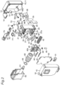
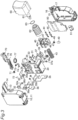
- Attached drawings from Fig. 1A to Fig. 9B show the case where a contact mechanism according to an embodiment of the present invention is applied to a trigger switch of an electric tool. That is, as shown in Fig. 2 and Fig. 3 , the trigger switch is configured such that internal constitutional parts such as a base 20, a plunger 40, and a printed circuit board 50 are incorporated into a housing 10 which is formed by combining a first cover 11 and a second cover 15, and a trigger 60 and a switch lever 70 are mounted on the housing 10.
- a semi-circular fitting recess 12 for supporting the switch lever 70 described later is formed on a portion of an upper surface of the first cover 11 on a lateral side of the first cover 11.
- a semi-circular rib 13 for supporting an operating rod 61 of the trigger 60 is formed on an outer surface of the first cover 11 at a position directly below the fitting recess 12.
- a guide member 14 is formed on the first cover 11 in a projecting manner on one side of the first cover 11 such that the guide member 14 is disposed adjacently to the fitting recess 12.
- the second cover 15 has a front shape which allows the second cover 15 to contact with the first cover 11.
- a semi-circular fitting recess 16 for supporting the switch lever 70 described later is formed on a portion on one side of an upper surface of the second cover 15.
- a semi-circular rib 17 for supporting the operating rod 61 of the trigger 60 is formed on an outer surface of the second cover 15 at a position directly below the fitting recess 16.
- a joining surface of the secondcover 15 is integrally joined to the first cover 11 by ultrasonic welding or by an adhesive agent except for portions of the joining surface on which the operating rod 61 of the trigger 60 and the switch lever 70 are mounted.
- the base 20 has a shape which is obtained by cutting away one side surface from a box shape.
- a positioning recessed portion 21 for positioning the switch lever 70 is formed on a portion on one side of an upper portion of the base 20.
- a serrated uneven portion 22 for generating click feeling is formed on a portion on the other side of the upper portion of the base 20.
- a recessed portion 23 for disposing a relay terminal described later therein is formed between the positioning recessed portion 21 and the uneven portion 22 for generating click feeling.
- a positioning recessed portion 24 for positioning a movable contact spring 38 described later and a pedestal portion 25 for restricting the position of a current-passing movable contact piece 39 are formed in a juxtaposed manner on a bottom surface of the base 20 which forms a lower surface of the base 20.
- a bent common relay terminal 30 and a bent first relay terminal 31 are disposed in the recessed portion 23 for disposing a relay terminal such that the common relay terminal 30 and the first relay terminal 31 become coplanar with each other.
- the common relay terminal 30 rotatably supports a relay movable contact piece 33 inserted into a support hole 30a formed in the common relay terminal 30 by way of a relay movable contact spring 34.
- a second relay terminal 32 which has a relay fixing contact 32a is mounted in a fitting hole 26 formed in the base 20.
- a relay movable contact 33a mounted on one end portion of the relay movable contact piece 33 faces the relay fixing contact 32a fixed to the second relay terminal 32 by swaging such that the relay movable contact 33a can be brought into contact with or separated from the relay fixing contact 32a ( Fig. 6B ).
- the base 20 is configured such that a fixed contact terminal 35 and a movable contact terminal 36 are press-fitted into and fixed to a lower side of the base 20 from sideward.
- An open/close fixed contact 35a and a current-passing fixed contact 35b which form a pair are fixed to the fixed contact terminal 35 by swaging.
- a support hole 36a and a notched portion 36b are formed on an upper end portion of the movable contact terminal 36 in a juxtaposed manner.
- An open/close movable contact piece 37 is inserted into the support hole 36a, and the open/close movable contact piece 37 is rotatably supported by the support hole 36a by way of a movable contact spring 38.
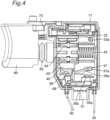
- a current-passing movable contact piece 39 is rotatably supported by the notched portion 36b ( Fig. 4 ) .
- an open/close movable contact 37a and a current-passing movable contact 39a mounted on the open/close movable contact piece 37 and the current-passing movable contact piece 39 respectively face the open/close fixed contact 35a and the current-passing fixed contact 35b mounted on the fixed contact terminal 35 such that the open/close movable contact 37a and the current-passing movable contact 39a can be brought into contact with or separated from the open/close fixed contact 35a and the current-passing fixed contact 35b.
- the plunger 40 has an outer shape which allows the plunger 40 to be slidably movable in the base 20.
- a through hole 41 is formed in the plunger 40 such that the through hole 41 penetrates the plunger 40 sideward.
- a pair of guide grooves 42a, 42b is formed on one outer surface of the plunger 40 in a juxtaposed manner.
- the plunger 40 has the structure where a restoring spring 43 is insertable into the through hole 41, and sliders 44, 45 can be press-fitted into and fixed to the pair of guide grooves 42a, 42b respectively. With such a configuration, the plunger 40 can be housed in the base 20 such that the plunger 40 is reciprocable in the axial direction by way of the restoring spring 43.
- an operating portion 46 having a tapered surface is formed on a bottom surface of the plunger 40 in a projecting manner, and an insertion hole 47 is formed in the plunger 40 at a position disposed adjacently to the operating portion 46.
- the plunger 40 has the structure where a coil spring 48 and an operating piece 49 are inserted into the insertion hole 47 so that the operating piece 49 is biased by the coil spring 48.
- the printed circuit board 50 has a front shape which allows the printed circuit board 50 to cover an opening portion of the base 20.
- Slide resistors not shown in the drawing are printed on a surface of the printed circuit board 50 which faces inward.
- a microcomputer is mounted on the printed circuit board 50.
- a socket 51 is mounted on a lower end portion of the printed circuit board 50.
- the printed circuit board 50 can be integrally mounted on the base 20 which houses the plunger 40 therein by assembling the printed circuit board 50 on the base 20 by fitting and by electrically connecting the common relay terminal 30, the first relay terminal 31 and the like to the printed circuit board 50.
- the pair of sliders 44, 45 mounted on the plunger 40 slides along the slide resistors printed on the printed circuit board 50 so that a resistance value is changed.
- the trigger 60 includes the operating rod 61 which projects sideward. As shown in Fig. 5 , one end portion of a bellow-shaped cylindrical body 62 into which the operating rod 61 is inserted is fixed by a coil ring 63 to prevent the removal of the bellow-shaped cylindrical body 62.
- the trigger 60 can be integrally mounted on the plunger 40 by making a distal end portion of the operating rod 61 projecting from the bellow-shaped cylindrical body 62 engage with an engaging hole 40a formed in the plunger 40 ( Fig. 3 ) by slidable engagement.
- the other end portion of the bellow-shaped cylindrical body 62 into which the operating rod 61 is inserted is made to engage with semi-circular ribs 13, 17 of the first and second covers 11, 15 so that the bellow-shaped cylindrical body 62 has the waterproof structure.
- a steel ball 72 is incorporated into one end portion of the switch lever 70 by way of a coil spring 71 such that the steel ball 72 is biased toward the outside, while as shown in Fig. 3 , a rotatable contact piece 74 having a U-shape in cross section is mounted on a lower surface of the switch lever 70 on one end side by way of a coil spring 73.
- a rotary shaft portion 76 is formed in a projecting manner coaxially with a flange portion 75 which is positioned at an intermediate portion of the switch lever 70 and also directly below the flange portion 75.
- the rotary shaft portion 76 is positioned in the positioning recessed portion 21 of the base 20, and the flange portion 75 can be rotatably supported by the semi-circular fitting recesses 12, 16 of the first and second covers 11, 15 by way of a seal ring 77.
- the steel ball 72 biased by the coil spring 71 engages with the uneven portion 22 for generating click feeling which is formed on the base 20 and hence, click feeling can be acquired by manipulating the switch lever 70.
- the second relay terminal 32 to which the common relay terminal 30, the first relay terminal 31, and the relay fixing contact 32a are fixed by swaging is mounted on the base 20.
- the relay movable contact piece 33 on which the relay movable contact 33a is disposed is rotatably supported by the support hole 30a formed in the common relay terminal 30 by way of the relay movable contact spring 34.
- the relay movable contact 33a faces the relay fixing contact 32a such that the relay movable contact 33a can be brought into contact with or separated from the relay fixing contact 32a.
- the fixed contact terminal 35 and the movable contact terminal 36 having the open/close fixed contact 35a and the current-passing fixed contact 35b respectively are mounted on the base 20.
- an open/close movable contact piece 37 to which the open/close movable contact 37a is fixed by swaging is inserted into the support hole 36a formed in the movable contact terminal 36.
- the open/close movable contact piece 37 is rotatably supported by the support hole 36a formed in the movable contact terminal 36 by way of the movable contact spring 38 having the lower end portion thereof positioned in the positioning recessed portion 24 of the base 20.
- the current-passing movable contact piece 39 having the current-passing movable contact 39a is rotatably supported by the notched portion 36b formed in the movable contact terminal 36.
- the open/close movable contact 37a and the current-passing movable contact 39a face the open/close fixed contact 35a and the current-passing fixed contact 35b respectively such that the open/close movable contact 37a and the current-passing movable contact 39a can be brought into contact with or separated from the open/close fixed contact 35a and the current-passing fixed contact 35b.
- sliders 44, 45 are press-fitted into and fixed to the pair of guide grooves 42a, 42b formed in the plunger 40 respectively and, at the same time, the coil spring 48 and the operating piece 49 are inserted into the insertion hole 47 formed in the plunger 40 ( Fig. 3 ), and is held by a jig not shown in the drawing.
- the operating rod 61 of the trigger 60 is inserted into the bellow-shaped cylindrical body 62, and the operating rod 61 is fixed on the bellow-shaped cylindrical body 62 by the coil ring 63 so as to prevent the removal of the bellow-shaped cylindrical body 62 and, the distal end portion of the operating rod 61 projecting from the bellow-shaped cylindrical body 62 is fitted in the engaging hole 40a formed in the plunger 40 by slide engagement from a side so that the plunger 40 and the operating rod 61 are integrally joined with each other. Then, in a state where the restoring spring 43 is inserted into the through hole 41, the plunger 40 is housed in the base 20 such that the plunger 40 can be slidably moved.
- the printed circuit board 50 on which the socket 51 is mounted is mounted on the opening portion of the base 20 by fitting and, thereafter, the common relay terminal 30, the first relay terminal 31, the second relay terminal 32, the fixed contact terminal 35 and, the movable contact terminal 36 are electrically connected to the printed circuit board 50.
- the switch lever 70 is formed such that while the seal ring 77 is mounted on the flange portion 75 of the switch lever 70, the coil spring 71 and the steel ball 72 are incorporated into one end portion of the switch lever 70 by way of a jig not shown in the drawing and, the coil spring 73 and the rotatable contact piece 74 are mounted on the lower surface of the switch lever 70 on one end side. Then, the rotary shaft portion 76 of the switch lever 70 is positioned in the positioning recessed portion 21 of the base 20 in a rotatable manner. Then, the first and second covers 11, 15 are mounted on the base 20 from both sides so that the removal of the switch lever 70 is prevented.
- the opening edge portion of the seal ring 77 is fitted in the semi-circular ribs 13, 17 of the first and second covers 11, 15.
- the first and second covers 11, 15 are joined to each other by ultrasonic welding or by an adhesive agent so that the first and second covers 11, 15 are integrally formed with each other.
- the open/close movable contact piece 37 is biased by the movable contact spring 38 ( Fig. 5 )
- the position of the open/close movable contact piece 37 is restricted to the operating portion 46 of the plunger 40 which is biased by the restoring spring 43
- the open/close movable contact 37a faces the open/close fixed contact 35a such that the open/close movable contact 37a can be brought into contact with or separated from the open/close fixed contact 35a.
- the position of the current-passing movable contact piece 39 rotatably supported which is supported in a rotatable manner is restricted by being pressed by the operating piece 49 mounted on the plunger 40.
- the end portion of the current -passing movable contact piece 39 is brought into pressure contact with the pedestal portion 25 of the base ( Figs. 4 , 5 ) and, at the same time, the current-passing movable contact 39a faces the current-passing fixed contact 35b such that the current-passing movable contact 39a can be brought into contact with or separated from the current-passing fixed contact 35b.
- the coil spring 48 is not shown in Fig. 5 .
- the plunger 40 which engages with the operating rod 61 of the trigger 60 moves in a sliding manner. Accordingly, the sliders 44, 45 mounted on the plunger 40 slide on the printed circuit board 50. As the sliders 44, 45 slide, resistance values are decreased so that an amount of electric current which flows through the printed circuit board 50 is increased whereby an operation lamp or the like not shown in the drawing is turned on.
- the restriction imposed on the position of the relay movable contact piece 33 by the stepped portion 40b of the plunger 40 is released so that the relay movable contact piece 33 is rotated by the spring force of the relay movable contact spring 34 . Accordingly, the relay movable contact 33a is brought into contact with the relay fixing contact 32a, and a rated electric current flows through the printed circuit board 50. Substantially at the same time, the restriction imposed on the position of the open/close movable contact piece 37 by the operating portion 46 of the plunger 40 is released.
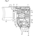
- the open/close movable contact piece 37 is rotated by a spring force of the movable contact spring 38, and the open/close movable contact 37a is brought into contact with the open/close fixed contact 35a (see Fig. 7 and Fig. 9 ).
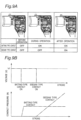
- the operating rod 61 When the trigger 60 is further depressed, the operating rod 61 is pushed to a depth side of the base 20 so that the operating piece 49 mounted on the plunger 40 rotates the current-passing movable contact piece 39. Accordingly, the current-passing movable contact 39a is brought into contact with the current-passing fixed contact 35b ( Fig. 8 ) and, at the same time, a sliding resistance value becomes substantially zero. As a result, maximum electric currents flow through the sliders 44, 45, and a signal is outputted from the microcomputer not shown in the drawing so as to set a rotational speed of the motor to a maximum value. For the sake of convenience of the description, a restoring spring 43 is not shown in Fig. 8 .
- a so-called batting-type movable contact piece is adopted where the open/close movable contact piece 37 is biased by the spring force of the movable contact spring 3 8 thus ensuring a contact pressure. Accordingly, it is possible to acquire advantageous effects that no slippage occurs in timing of contacting of the contacts, and there is no irregularity in an open/close characteristic.
- the plunger 40 when an operator decreases a force of depressing the trigger 60, the plunger 40 is pushed back by a spring force of the restoring spring 43, and the sliders 44, 45 slide on the printed circuit board 50 in the reverse direction.
- the operating piece 49 of the plunger 40 rotates the current-passing movable contact piece 39 in the direction opposite to the above-mentioned direction and hence, the current-passing movable contact 39a is separated from the current-passing fixed contact 35b and, thereafter, one end portion of the current-passing movable contact piece 39 is brought into pressure contact with the pedestal portion 25 of the base 20.
- the open/close movable contact piece 37 is rotated by the operating portion 46 of the plunger 40 against the spring force of the movable contact spring 38, and the open/close movable contact 37a is separated from the open/close fixed contact 35a.
- the relay movable contact piece 33 is rotated by the stepped portion of the plunger 40 against the spring force of the relay movable contact spring 34, and the relay movable contact 33a is separated from the relay fixing contact 32a and, thereafter, the sliders 44, 45 return to original positions.
- the contact mechanism according to the present invention is not limited to the above-mentioned trigger switch and is also applicable to other switches.
Landscapes
- Engineering & Computer Science (AREA)
- Mechanical Engineering (AREA)
- Push-Button Switches (AREA)
- Rotary Switch, Piano Key Switch, And Lever Switch (AREA)
- Portable Power Tools In General (AREA)
Claims (6)
- Kontaktmechanismus umfassend:ein Betätigungselement (40), das sich in Bezug auf ein Gehäuse (10) wechselseitig bewegt;ein beweglicher Kontaktanschluss (36), der durch das Gehäuse (10) aufgenommen ist; ein Paar bewegliche Kontaktstücke (37, 39), die durch dasGehäuse (10) aufgenommen sind und an dem beweglichen Kontaktanschluss (36) nebeneinander derart angebracht sind, dass das Paar beweglicher Kontaktstücke (37, 39) mit der wechselseitigen Bewegung des Betätigungselements (40) drehbar ist;einen beweglichen Öffnungs-/Schließ-Kontakt (37a), der an einem beweglichen Öffnungs-/Schließ-Kontaktstück (37) angebracht ist, das ein erstes bewegliches Kontaktstück der beweglichen Kontaktstücke (37, 39) bildet;einen stromdurchlässigen beweglichen Kontakt (39a), der an einem stromdurchlässigen beweglichen Kontaktstück (39) angebracht ist, das ein zweites bewegliches Kontaktstück der beweglichen Kontaktstücke (37, 39) bildet;einen festen Kontaktanschluss (35), der durch das Gehäuse (10) aufgenommen ist und dem beweglichen Kontaktanschluss (36) gegenüberliegt;einen festen Öffnungs-/Schließ-Kontakt (35a), der an dem festen Kontaktanschluss (35) derart angebracht ist, dass der bewegliche Öffnungs-/Schließ-Kontakt (37a) mit dem festen Öffnungs-/Schließ-Kontakt (35a) in Kontakt gebracht oder von diesem getrennt wird;einen stromdurchlässigen Festkontakt (35b), der an dem Festkontaktanschluss (35) derart angebracht ist, dass der stromdurchlässige bewegliche Kontakt (39a) mit dem stromdurchlässigen Festkontakt (35b) in Kontakt gebracht oder von diesem getrennt wird; undein Federelement (48), das an dem Betätigungselement (40) angebracht ist, wobei die Feder derart angeordnet ist, dass sie das bewegliche Öffnungs-/Schließ-Kontaktstück (37) in eine Kontaktschließrichtung vorspannt, wobei der Kontaktmechanismus derart eingerichtet ist, dass mit der wechselseitigen Bewegung des Betätigungselements (40), das bewegliche Öffnungs-/Schließ-Kontaktstück (37) durch die Vorspannung des Federelements (48) derart gedreht wird, dass der bewegliche Öffnungs-/Schließ-Kontakt (37a) in Druckkontakt mit dem festen Öffnungs-/Schließ-Kontakt (35a) gebracht wird, und das Betätigungselement (40) das bewegliche stromdurchlässige Kontaktstück (39) derart dreht, um den beweglichen Stromdurchgangskontakt (39a) in Druckkontakt mit dem festen stromdurchlässigen Kontakt (35b) zu bringen, dadurch gekennzeichnet, dassder Kontaktmechanismus darüber hinaus einen Sockelabschnitt (25) zur Begrenzung einer Position des stromdurchlässigen beweglichen Kontaktstücks (39) umfasst,der Sockelabschnitt (25) in einer Basis (20) ausgebildet ist, der auf dem Gehäuse (10) angebracht ist, wobeidas stromdurchlässige bewegliche Kontaktstück (39) betätigt wird, indem es durch ein elastisch vorgespanntes Betätigungsstück (49) gedrückt wird, das durch das Federelement (48) vorgespannt wird, und das bewegliche Kontaktstück (39) in Druckkontakt mit dem Sockelabschnitt (25) der Basis (20) gebracht wird.
- Kontaktmechanismus gemäß Anspruch 1, wobei das Betätigungselement (40) umfasst:einen Betätigungsabschnitt (46), der das bewegliche Öffnungs-/Schließ-Kontaktstück (37) in eine Position beschränkt, in der der bewegliche Öffnungs-/Schließ-Kontakt (37a) von dem festen Öffnungs-/Schließ-Kontakt (35a) gegen die Vorspannung des Federelements (48) in der Kontaktschließrichtung derart getrennt ist, dass die Beschränkung der Position durch Bewegung in eine Richtung der wechselseitigen Bewegung des Betätigungselements (40) lösbar ist; undein Betätigungselement (49), das die Drehung des stromdurchlässigen beweglichen Kontaktstücks (39) derart einschränkt, dass die Beschränkung der Drehung durch weitere Bewegung in eine Richtung der wechselseitigen Bewegung des Betätigungselements (40) lösbar ist, undwobei, nachdem die Beschränkung der Position des beweglichen Öffnungs-/Schließ-Kontaktstücks (37) durch den Betätigungsabschnitt mit der Bewegung in eine Richtung des Betätigungselements (40) gelöst ist, das bewegliche Öffnungs-/Schließ-Kontaktstück (37) in einer Kontaktschließrichtung durch den Betätigungsabschnitt durch dieVorspannung des Federelements (48) in der Kontaktschließrichtung gedreht wird, und der bewegliche Öffnungs-/Schließ-Kontakt (37a) in Druckkontakt mit dem festen Öffnungs-/Schließ-Kontakt (35a) gebracht wird, und dann, nachdem die Drehbeschränkung des stromdurchlässigen beweglichen Kontaktstücks (39) durch das Betätigungselement (49) mit der weiteren Bewegung des Betätigungselements (40) gelöst wird, das stromdurchlässige bewegliche Kontaktstück (39) gedreht wird, und dann der stromdurchlässige bewegliche Kontakt (39a) in Druckkontakt mit dem stromdurchlässigen festen Kontakt (35b) gebracht wird.
- Kontaktmechanismus gemäß Anspruch 1 oder 2,
wobei das Betätigungselement umfasst:einen Betätigungsabschnitt (46), der das bewegliche Öffnungs-/Schließ-Kontaktstück (37) in eine Position beschränkt, in der der bewegliche Öffnungs-/Schließ-Kontakt (37a) von dem festen Öffnungs-/Schließ-Kontakt (35a) gegen die Vorspannung des Federelements (48) in der Kontaktschließrichtung derart getrennt ist, dass die Beschränkung der Position durch Bewegen in eine Richtung der wechselseitigen Bewegung des Betätigungselements (40) lösbar ist; undein Betätigungselement (49), das die Drehung des stromdurchlässigen beweglichen Kontaktstücks (39) derart einschränkt, dass die Beschränkung der Drehung durch weitere Bewegung in einer Richtung der wechselseitigen Bewegung des Betätigungselements (40) lösbar ist, undwobei, nachdem das Betätigungsstück (49) das stromdurchlässige bewegliche Kontaktstück (39) in eine Richtung entgegengesetzt zu einer Kontaktschließrichtung mit einer Rückbetätigung entgegengesetzt zu der Bewegung in eine Richtung des Betätigungselements (40) dreht, der stromdurchlässige bewegliche Kontakt (39a) von dem stromdurchlässigen festen Kontakt (35b) getrennt wird, und danach, mit der weiteren Rückbetätigung des Betätigungselements (40), das bewegliche Öffnungs-/Schließ-Kontaktstück (37) gegen die Vorspannung des Federelements (48) durch den Betätigungsabschnitt des Betätigungselements (40) gedreht wird, und dann der bewegliche Öffnungs-/Schließ-Kontakt (37a) von dem festen Öffnungs-/Schließ-Kontakt (35a) getrennt wird. - Kontaktmechanismis gemäß einem der Ansprüche 1 bis 3, wobei
ein unterer Endabschnitt einer Schraubenfeder (48), die das Federelement bildet, in Kontakt mit einer Innenfläche des Gehäuses (10) gebracht wird. - Auslöseschalter umfassend den Kontaktmechanismus gemäß einem der Ansprüche 1 bis 4.
- Elektrisches Werkzeug umfassend einen Auslöseschalter gemäß Anspruch 5.
Applications Claiming Priority (2)
| Application Number | Priority Date | Filing Date | Title |
|---|---|---|---|
| JP2014026824A JP5773001B2 (ja) | 2014-02-14 | 2014-02-14 | 接点機構およびこれを用いたトリガースイッチ,電動工具 |
| PCT/JP2014/070778 WO2015122035A1 (ja) | 2014-02-14 | 2014-08-06 | 接点機構およびこれを用いたトリガースイッチ,電動工具 |
Publications (3)
| Publication Number | Publication Date |
|---|---|
| EP3107110A1 EP3107110A1 (de) | 2016-12-21 |
| EP3107110A4 EP3107110A4 (de) | 2017-09-20 |
| EP3107110B1 true EP3107110B1 (de) | 2024-10-09 |
Family
ID=53799794
Family Applications (1)
| Application Number | Title | Priority Date | Filing Date |
|---|---|---|---|
| EP14882513.6A Active EP3107110B1 (de) | 2014-02-14 | 2014-08-06 | Kontaktmechanismus, auslöseschalter umfassend den kontaktmechanismus und elektrisches werkzeug |
Country Status (5)
| Country | Link |
|---|---|
| US (1) | US9916944B2 (de) |
| EP (1) | EP3107110B1 (de) |
| JP (1) | JP5773001B2 (de) |
| CN (1) | CN105378882B (de) |
| WO (1) | WO2015122035A1 (de) |
Families Citing this family (13)
| Publication number | Priority date | Publication date | Assignee | Title |
|---|---|---|---|---|
| JP2017168268A (ja) * | 2016-03-15 | 2017-09-21 | オムロン株式会社 | トリガースイッチ、および、それを用いた電動具 |
| CN206163364U (zh) * | 2016-08-26 | 2017-05-10 | 东莞辰达电器有限公司 | 一种可调校输出功率的省力按钮开关 |
| JP2018051658A (ja) * | 2016-09-27 | 2018-04-05 | オムロン株式会社 | 電動工具 |
| EP3326758B1 (de) * | 2016-11-28 | 2022-08-10 | Guido Valentini | Elektrowerkzeug |
| JP6690525B2 (ja) * | 2016-12-28 | 2020-04-28 | オムロン株式会社 | スイッチの接点構造、トリガースイッチ及び電動工具 |
| JP6428814B2 (ja) | 2017-03-14 | 2018-11-28 | オムロン株式会社 | トリガースイッチ |
| JP6952872B2 (ja) * | 2018-03-20 | 2021-10-27 | 三菱電機株式会社 | 接触子及び接触子の製造方法 |
| DE102018206876A1 (de) * | 2018-05-04 | 2019-11-07 | Robert Bosch Gmbh | Werkzeugmaschinenvorrichtung |
| CN110060897B (zh) * | 2019-05-23 | 2024-04-05 | 科都电气股份有限公司 | 一种集成开关 |
| CN110911181A (zh) * | 2019-12-03 | 2020-03-24 | 苏州华之杰电讯股份有限公司 | 应用于电动工具开关的动触组模块 |
| CN114974968B (zh) * | 2022-06-02 | 2025-08-19 | 浙江佳奔电子有限公司 | 带瞬动结构的长行程扳机开关 |
| CN115148523B (zh) * | 2022-09-06 | 2022-11-18 | 江苏鑫润轨道交通车辆配件有限公司 | 一种手工电动工具用电开关 |
| JP2025124241A (ja) * | 2024-02-14 | 2025-08-26 | 株式会社マキタ | 電動工具用コントロールモジュール及び電動工具 |
Family Cites Families (11)
| Publication number | Priority date | Publication date | Assignee | Title |
|---|---|---|---|---|
| JPH06223674A (ja) * | 1993-01-27 | 1994-08-12 | Omron Corp | トリガースイッチ |
| US6717080B1 (en) * | 2003-05-22 | 2004-04-06 | Defond Components Limited | Power tool trigger assembly |
| EP1691385B1 (de) | 2005-02-09 | 2010-05-05 | Satori S-Tech Co., Ltd. | Triggerschalter |
| JP2006218560A (ja) * | 2005-02-09 | 2006-08-24 | Satori S-Tech Co Ltd | トリガースイッチ |
| JP5066874B2 (ja) * | 2006-09-19 | 2012-11-07 | オムロン株式会社 | トリガスイッチ |
| JP5033543B2 (ja) | 2007-08-29 | 2012-09-26 | 佐鳥エス・テック株式会社 | トリガースイッチ |
| JP5028236B2 (ja) * | 2007-11-30 | 2012-09-19 | 佐鳥エス・テック株式会社 | トリガースイッチ |
| JP2009199981A (ja) * | 2008-02-25 | 2009-09-03 | Satori S-Tech Co Ltd | 電動工具用スイッチ |
| JP5323524B2 (ja) * | 2009-02-13 | 2013-10-23 | 富士工業株式会社 | シーソー型スイッチ |
| JP4879335B2 (ja) | 2010-04-05 | 2012-02-22 | 佐鳥エス・テック株式会社 | トリガースイッチ |
| JP5270773B2 (ja) | 2012-02-17 | 2013-08-21 | 佐鳥エス・テック株式会社 | トリガースイッチ |
-
2014
- 2014-02-14 JP JP2014026824A patent/JP5773001B2/ja active Active
- 2014-08-06 US US15/117,746 patent/US9916944B2/en active Active
- 2014-08-06 EP EP14882513.6A patent/EP3107110B1/de active Active
- 2014-08-06 CN CN201480001998.5A patent/CN105378882B/zh active Active
- 2014-08-06 WO PCT/JP2014/070778 patent/WO2015122035A1/ja not_active Ceased
Also Published As
| Publication number | Publication date |
|---|---|
| US20160365202A1 (en) | 2016-12-15 |
| EP3107110A1 (de) | 2016-12-21 |
| JP2015153626A (ja) | 2015-08-24 |
| CN105378882A (zh) | 2016-03-02 |
| CN105378882B (zh) | 2017-08-04 |
| US9916944B2 (en) | 2018-03-13 |
| EP3107110A4 (de) | 2017-09-20 |
| WO2015122035A1 (ja) | 2015-08-20 |
| JP5773001B2 (ja) | 2015-09-02 |
Similar Documents
| Publication | Publication Date | Title |
|---|---|---|
| EP3107110B1 (de) | Kontaktmechanismus, auslöseschalter umfassend den kontaktmechanismus und elektrisches werkzeug | |
| EP2767997B1 (de) | Hebeldichtungsstruktur und elektrisches Werkzeug damit | |
| KR102229437B1 (ko) | 스위치의 접점 구조, 트리거 스위치 및 전동 공구 | |
| EP2996128A1 (de) | Elektrischer schalter | |
| US20180082805A1 (en) | Electric switch | |
| US20130140167A1 (en) | Trigger switch | |
| JP6410571B2 (ja) | スイッチ装置 | |
| JP6011664B2 (ja) | 接点機構およびこれを用いたスイッチ | |
| EP3591681B1 (de) | Schalter | |
| JP2006216259A (ja) | レバースイッチ装置 | |
| US20170018380A1 (en) | Switch device | |
| JP2007035402A (ja) | 電気装置の操作機構 | |
| JPH021781Y2 (de) | ||
| JP6464841B2 (ja) | 接点機構およびこれを用いたスイッチ | |
| JP2005153055A (ja) | 電動工具用スイッチ | |
| JP2003288825A (ja) | 電力遮断器 | |
| EP3133629A1 (de) | Dreheingabevorrichtung | |
| JP2007305363A (ja) | スライド操作型電気部品 | |
| JP2011230689A (ja) | シフトレバー装置 | |
| JP2011028958A (ja) | スライド操作型電気部品 | |
| JP2001067986A (ja) | 複合操作型スイッチ |
Legal Events
| Date | Code | Title | Description |
|---|---|---|---|
| PUAI | Public reference made under article 153(3) epc to a published international application that has entered the european phase |
Free format text: ORIGINAL CODE: 0009012 |
|
| STAA | Information on the status of an ep patent application or granted ep patent |
Free format text: STATUS: REQUEST FOR EXAMINATION WAS MADE |
|
| 17P | Request for examination filed |
Effective date: 20160905 |
|
| AK | Designated contracting states |
Kind code of ref document: A1 Designated state(s): AL AT BE BG CH CY CZ DE DK EE ES FI FR GB GR HR HU IE IS IT LI LT LU LV MC MK MT NL NO PL PT RO RS SE SI SK SM TR |
|
| AX | Request for extension of the european patent |
Extension state: BA ME |
|
| DAX | Request for extension of the european patent (deleted) | ||
| A4 | Supplementary search report drawn up and despatched |
Effective date: 20170818 |
|
| RIC1 | Information provided on ipc code assigned before grant |
Ipc: H01H 13/66 20060101ALI20170811BHEP Ipc: B25F 5/00 20060101ALI20170811BHEP Ipc: H01H 13/08 20060101AFI20170811BHEP Ipc: H01H 1/58 20060101ALN20170811BHEP Ipc: H01H 9/06 20060101ALN20170811BHEP |
|
| STAA | Information on the status of an ep patent application or granted ep patent |
Free format text: STATUS: EXAMINATION IS IN PROGRESS |
|
| 17Q | First examination report despatched |
Effective date: 20200406 |
|
| REG | Reference to a national code |
Ref country code: DE Ref legal event code: R079 Free format text: PREVIOUS MAIN CLASS: H01H0013660000 Ipc: H01H0013080000 Ref country code: DE Ref legal event code: R079 Ref document number: 602014091003 Country of ref document: DE Free format text: PREVIOUS MAIN CLASS: H01H0013660000 Ipc: H01H0013080000 |
|
| GRAP | Despatch of communication of intention to grant a patent |
Free format text: ORIGINAL CODE: EPIDOSNIGR1 |
|
| STAA | Information on the status of an ep patent application or granted ep patent |
Free format text: STATUS: GRANT OF PATENT IS INTENDED |
|
| RIC1 | Information provided on ipc code assigned before grant |
Ipc: H01H 1/58 20060101ALN20240223BHEP Ipc: H01H 9/06 20060101ALN20240223BHEP Ipc: B25F 5/00 20060101ALI20240223BHEP Ipc: H01H 13/66 20060101ALI20240223BHEP Ipc: H01H 13/08 20060101AFI20240223BHEP |
|
| INTG | Intention to grant announced |
Effective date: 20240328 |
|
| GRAS | Grant fee paid |
Free format text: ORIGINAL CODE: EPIDOSNIGR3 |
|
| GRAA | (expected) grant |
Free format text: ORIGINAL CODE: 0009210 |
|
| STAA | Information on the status of an ep patent application or granted ep patent |
Free format text: STATUS: THE PATENT HAS BEEN GRANTED |
|
| AK | Designated contracting states |
Kind code of ref document: B1 Designated state(s): AL AT BE BG CH CY CZ DE DK EE ES FI FR GB GR HR HU IE IS IT LI LT LU LV MC MK MT NL NO PL PT RO RS SE SI SK SM TR |
|
| REG | Reference to a national code |
Ref country code: GB Ref legal event code: FG4D |
|
| REG | Reference to a national code |
Ref country code: CH Ref legal event code: EP |
|
| REG | Reference to a national code |
Ref country code: DE Ref legal event code: R096 Ref document number: 602014091003 Country of ref document: DE |
|
| REG | Reference to a national code |
Ref country code: IE Ref legal event code: FG4D |
|
| REG | Reference to a national code |
Ref country code: LT Ref legal event code: MG9D |
|
| REG | Reference to a national code |
Ref country code: NL Ref legal event code: MP Effective date: 20241009 |
|
| REG | Reference to a national code |
Ref country code: AT Ref legal event code: MK05 Ref document number: 1731525 Country of ref document: AT Kind code of ref document: T Effective date: 20241009 |
|
| PG25 | Lapsed in a contracting state [announced via postgrant information from national office to epo] |
Ref country code: NL Free format text: LAPSE BECAUSE OF FAILURE TO SUBMIT A TRANSLATION OF THE DESCRIPTION OR TO PAY THE FEE WITHIN THE PRESCRIBED TIME-LIMIT Effective date: 20241009 |
|
| PG25 | Lapsed in a contracting state [announced via postgrant information from national office to epo] |
Ref country code: NL Free format text: LAPSE BECAUSE OF FAILURE TO SUBMIT A TRANSLATION OF THE DESCRIPTION OR TO PAY THE FEE WITHIN THE PRESCRIBED TIME-LIMIT Effective date: 20241009 |
|
| PG25 | Lapsed in a contracting state [announced via postgrant information from national office to epo] |
Ref country code: IS Free format text: LAPSE BECAUSE OF FAILURE TO SUBMIT A TRANSLATION OF THE DESCRIPTION OR TO PAY THE FEE WITHIN THE PRESCRIBED TIME-LIMIT Effective date: 20250209 Ref country code: HR Free format text: LAPSE BECAUSE OF FAILURE TO SUBMIT A TRANSLATION OF THE DESCRIPTION OR TO PAY THE FEE WITHIN THE PRESCRIBED TIME-LIMIT Effective date: 20241009 Ref country code: PT Free format text: LAPSE BECAUSE OF FAILURE TO SUBMIT A TRANSLATION OF THE DESCRIPTION OR TO PAY THE FEE WITHIN THE PRESCRIBED TIME-LIMIT Effective date: 20250210 |
|
| PG25 | Lapsed in a contracting state [announced via postgrant information from national office to epo] |
Ref country code: FI Free format text: LAPSE BECAUSE OF FAILURE TO SUBMIT A TRANSLATION OF THE DESCRIPTION OR TO PAY THE FEE WITHIN THE PRESCRIBED TIME-LIMIT Effective date: 20241009 |
|
| PG25 | Lapsed in a contracting state [announced via postgrant information from national office to epo] |
Ref country code: BG Free format text: LAPSE BECAUSE OF FAILURE TO SUBMIT A TRANSLATION OF THE DESCRIPTION OR TO PAY THE FEE WITHIN THE PRESCRIBED TIME-LIMIT Effective date: 20241009 |
|
| PG25 | Lapsed in a contracting state [announced via postgrant information from national office to epo] |
Ref country code: ES Free format text: LAPSE BECAUSE OF FAILURE TO SUBMIT A TRANSLATION OF THE DESCRIPTION OR TO PAY THE FEE WITHIN THE PRESCRIBED TIME-LIMIT Effective date: 20241009 |
|
| PG25 | Lapsed in a contracting state [announced via postgrant information from national office to epo] |
Ref country code: NO Free format text: LAPSE BECAUSE OF FAILURE TO SUBMIT A TRANSLATION OF THE DESCRIPTION OR TO PAY THE FEE WITHIN THE PRESCRIBED TIME-LIMIT Effective date: 20250109 |
|
| PG25 | Lapsed in a contracting state [announced via postgrant information from national office to epo] |
Ref country code: LV Free format text: LAPSE BECAUSE OF FAILURE TO SUBMIT A TRANSLATION OF THE DESCRIPTION OR TO PAY THE FEE WITHIN THE PRESCRIBED TIME-LIMIT Effective date: 20241009 Ref country code: GR Free format text: LAPSE BECAUSE OF FAILURE TO SUBMIT A TRANSLATION OF THE DESCRIPTION OR TO PAY THE FEE WITHIN THE PRESCRIBED TIME-LIMIT Effective date: 20250110 Ref country code: AT Free format text: LAPSE BECAUSE OF FAILURE TO SUBMIT A TRANSLATION OF THE DESCRIPTION OR TO PAY THE FEE WITHIN THE PRESCRIBED TIME-LIMIT Effective date: 20241009 |
|
| PG25 | Lapsed in a contracting state [announced via postgrant information from national office to epo] |
Ref country code: PL Free format text: LAPSE BECAUSE OF FAILURE TO SUBMIT A TRANSLATION OF THE DESCRIPTION OR TO PAY THE FEE WITHIN THE PRESCRIBED TIME-LIMIT Effective date: 20241009 |
|
| PG25 | Lapsed in a contracting state [announced via postgrant information from national office to epo] |
Ref country code: RS Free format text: LAPSE BECAUSE OF FAILURE TO SUBMIT A TRANSLATION OF THE DESCRIPTION OR TO PAY THE FEE WITHIN THE PRESCRIBED TIME-LIMIT Effective date: 20250109 |
|
| PG25 | Lapsed in a contracting state [announced via postgrant information from national office to epo] |
Ref country code: SM Free format text: LAPSE BECAUSE OF FAILURE TO SUBMIT A TRANSLATION OF THE DESCRIPTION OR TO PAY THE FEE WITHIN THE PRESCRIBED TIME-LIMIT Effective date: 20241009 |
|
| PG25 | Lapsed in a contracting state [announced via postgrant information from national office to epo] |
Ref country code: DK Free format text: LAPSE BECAUSE OF FAILURE TO SUBMIT A TRANSLATION OF THE DESCRIPTION OR TO PAY THE FEE WITHIN THE PRESCRIBED TIME-LIMIT Effective date: 20241009 |
|
| REG | Reference to a national code |
Ref country code: DE Ref legal event code: R097 Ref document number: 602014091003 Country of ref document: DE |
|
| PG25 | Lapsed in a contracting state [announced via postgrant information from national office to epo] |
Ref country code: EE Free format text: LAPSE BECAUSE OF FAILURE TO SUBMIT A TRANSLATION OF THE DESCRIPTION OR TO PAY THE FEE WITHIN THE PRESCRIBED TIME-LIMIT Effective date: 20241009 |
|
| PG25 | Lapsed in a contracting state [announced via postgrant information from national office to epo] |
Ref country code: RO Free format text: LAPSE BECAUSE OF FAILURE TO SUBMIT A TRANSLATION OF THE DESCRIPTION OR TO PAY THE FEE WITHIN THE PRESCRIBED TIME-LIMIT Effective date: 20241009 |
|
| PG25 | Lapsed in a contracting state [announced via postgrant information from national office to epo] |
Ref country code: SK Free format text: LAPSE BECAUSE OF FAILURE TO SUBMIT A TRANSLATION OF THE DESCRIPTION OR TO PAY THE FEE WITHIN THE PRESCRIBED TIME-LIMIT Effective date: 20241009 |
|
| PG25 | Lapsed in a contracting state [announced via postgrant information from national office to epo] |
Ref country code: CZ Free format text: LAPSE BECAUSE OF FAILURE TO SUBMIT A TRANSLATION OF THE DESCRIPTION OR TO PAY THE FEE WITHIN THE PRESCRIBED TIME-LIMIT Effective date: 20241009 |
|
| PG25 | Lapsed in a contracting state [announced via postgrant information from national office to epo] |
Ref country code: IT Free format text: LAPSE BECAUSE OF FAILURE TO SUBMIT A TRANSLATION OF THE DESCRIPTION OR TO PAY THE FEE WITHIN THE PRESCRIBED TIME-LIMIT Effective date: 20241009 |
|
| PLBE | No opposition filed within time limit |
Free format text: ORIGINAL CODE: 0009261 |
|
| STAA | Information on the status of an ep patent application or granted ep patent |
Free format text: STATUS: NO OPPOSITION FILED WITHIN TIME LIMIT |
|
| PG25 | Lapsed in a contracting state [announced via postgrant information from national office to epo] |
Ref country code: SE Free format text: LAPSE BECAUSE OF FAILURE TO SUBMIT A TRANSLATION OF THE DESCRIPTION OR TO PAY THE FEE WITHIN THE PRESCRIBED TIME-LIMIT Effective date: 20241009 |
|
| 26N | No opposition filed |
Effective date: 20250710 |
|
| PGFP | Annual fee paid to national office [announced via postgrant information from national office to epo] |
Ref country code: DE Payment date: 20250829 Year of fee payment: 12 |
|
| REG | Reference to a national code |
Ref country code: CH Ref legal event code: H13 Free format text: ST27 STATUS EVENT CODE: U-0-0-H10-H13 (AS PROVIDED BY THE NATIONAL OFFICE) Effective date: 20260324 |
|
| PG25 | Lapsed in a contracting state [announced via postgrant information from national office to epo] |
Ref country code: MC Free format text: LAPSE BECAUSE OF FAILURE TO SUBMIT A TRANSLATION OF THE DESCRIPTION OR TO PAY THE FEE WITHIN THE PRESCRIBED TIME-LIMIT Effective date: 20241009 |
|
| PG25 | Lapsed in a contracting state [announced via postgrant information from national office to epo] |
Ref country code: LU Free format text: LAPSE BECAUSE OF NON-PAYMENT OF DUE FEES Effective date: 20250806 |