EP3104261B1 - Fahrzeuginterne eingabevorrichtung - Google Patents
Fahrzeuginterne eingabevorrichtung Download PDFInfo
- Publication number
- EP3104261B1 EP3104261B1 EP16173228.4A EP16173228A EP3104261B1 EP 3104261 B1 EP3104261 B1 EP 3104261B1 EP 16173228 A EP16173228 A EP 16173228A EP 3104261 B1 EP3104261 B1 EP 3104261B1
- Authority
- EP
- European Patent Office
- Prior art keywords
- input device
- upper electrode
- operator
- areas
- vehicle input
- Prior art date
- Legal status (The legal status is an assumption and is not a legal conclusion. Google has not performed a legal analysis and makes no representation as to the accuracy of the status listed.)
- Active
Links
Images




Classifications
-
- G—PHYSICS
- G06—COMPUTING OR CALCULATING; COUNTING
- G06F—ELECTRIC DIGITAL DATA PROCESSING
- G06F3/00—Input arrangements for transferring data to be processed into a form capable of being handled by the computer; Output arrangements for transferring data from processing unit to output unit, e.g. interface arrangements
- G06F3/01—Input arrangements or combined input and output arrangements for interaction between user and computer
- G06F3/048—Interaction techniques based on graphical user interfaces [GUI]
- G06F3/0487—Interaction techniques based on graphical user interfaces [GUI] using specific features provided by the input device, e.g. functions controlled by the rotation of a mouse with dual sensing arrangements, or of the nature of the input device, e.g. tap gestures based on pressure sensed by a digitiser
- G06F3/0488—Interaction techniques based on graphical user interfaces [GUI] using specific features provided by the input device, e.g. functions controlled by the rotation of a mouse with dual sensing arrangements, or of the nature of the input device, e.g. tap gestures based on pressure sensed by a digitiser using a touch-screen or digitiser, e.g. input of commands through traced gestures
- G06F3/04886—Interaction techniques based on graphical user interfaces [GUI] using specific features provided by the input device, e.g. functions controlled by the rotation of a mouse with dual sensing arrangements, or of the nature of the input device, e.g. tap gestures based on pressure sensed by a digitiser using a touch-screen or digitiser, e.g. input of commands through traced gestures by partitioning the display area of the touch-screen or the surface of the digitising tablet into independently controllable areas, e.g. virtual keyboards or menus
-
- B—PERFORMING OPERATIONS; TRANSPORTING
- B60—VEHICLES IN GENERAL
- B60K—ARRANGEMENT OR MOUNTING OF PROPULSION UNITS OR OF TRANSMISSIONS IN VEHICLES; ARRANGEMENT OR MOUNTING OF PLURAL DIVERSE PRIME-MOVERS IN VEHICLES; AUXILIARY DRIVES FOR VEHICLES; INSTRUMENTATION OR DASHBOARDS FOR VEHICLES; ARRANGEMENTS IN CONNECTION WITH COOLING, AIR INTAKE, GAS EXHAUST OR FUEL SUPPLY OF PROPULSION UNITS IN VEHICLES
- B60K35/00—Instruments specially adapted for vehicles; Arrangement of instruments in or on vehicles
- B60K35/10—Input arrangements, i.e. from user to vehicle, associated with vehicle functions or specially adapted therefor
-
- B—PERFORMING OPERATIONS; TRANSPORTING
- B60—VEHICLES IN GENERAL
- B60K—ARRANGEMENT OR MOUNTING OF PROPULSION UNITS OR OF TRANSMISSIONS IN VEHICLES; ARRANGEMENT OR MOUNTING OF PLURAL DIVERSE PRIME-MOVERS IN VEHICLES; AUXILIARY DRIVES FOR VEHICLES; INSTRUMENTATION OR DASHBOARDS FOR VEHICLES; ARRANGEMENTS IN CONNECTION WITH COOLING, AIR INTAKE, GAS EXHAUST OR FUEL SUPPLY OF PROPULSION UNITS IN VEHICLES
- B60K35/00—Instruments specially adapted for vehicles; Arrangement of instruments in or on vehicles
- B60K35/20—Output arrangements, i.e. from vehicle to user, associated with vehicle functions or specially adapted therefor
- B60K35/25—Output arrangements, i.e. from vehicle to user, associated with vehicle functions or specially adapted therefor using haptic output
-
- B—PERFORMING OPERATIONS; TRANSPORTING
- B60—VEHICLES IN GENERAL
- B60K—ARRANGEMENT OR MOUNTING OF PROPULSION UNITS OR OF TRANSMISSIONS IN VEHICLES; ARRANGEMENT OR MOUNTING OF PLURAL DIVERSE PRIME-MOVERS IN VEHICLES; AUXILIARY DRIVES FOR VEHICLES; INSTRUMENTATION OR DASHBOARDS FOR VEHICLES; ARRANGEMENTS IN CONNECTION WITH COOLING, AIR INTAKE, GAS EXHAUST OR FUEL SUPPLY OF PROPULSION UNITS IN VEHICLES
- B60K35/00—Instruments specially adapted for vehicles; Arrangement of instruments in or on vehicles
- B60K35/50—Instruments characterised by their means of attachment to or integration in the vehicle
-
- B—PERFORMING OPERATIONS; TRANSPORTING
- B60—VEHICLES IN GENERAL
- B60K—ARRANGEMENT OR MOUNTING OF PROPULSION UNITS OR OF TRANSMISSIONS IN VEHICLES; ARRANGEMENT OR MOUNTING OF PLURAL DIVERSE PRIME-MOVERS IN VEHICLES; AUXILIARY DRIVES FOR VEHICLES; INSTRUMENTATION OR DASHBOARDS FOR VEHICLES; ARRANGEMENTS IN CONNECTION WITH COOLING, AIR INTAKE, GAS EXHAUST OR FUEL SUPPLY OF PROPULSION UNITS IN VEHICLES
- B60K35/00—Instruments specially adapted for vehicles; Arrangement of instruments in or on vehicles
- B60K35/60—Instruments characterised by their location or relative disposition in or on vehicles
-
- G—PHYSICS
- G06—COMPUTING OR CALCULATING; COUNTING
- G06F—ELECTRIC DIGITAL DATA PROCESSING
- G06F3/00—Input arrangements for transferring data to be processed into a form capable of being handled by the computer; Output arrangements for transferring data from processing unit to output unit, e.g. interface arrangements
- G06F3/01—Input arrangements or combined input and output arrangements for interaction between user and computer
- G06F3/03—Arrangements for converting the position or the displacement of a member into a coded form
- G06F3/041—Digitisers, e.g. for touch screens or touch pads, characterised by the transducing means
- G06F3/044—Digitisers, e.g. for touch screens or touch pads, characterised by the transducing means by capacitive means
- G06F3/0445—Digitisers, e.g. for touch screens or touch pads, characterised by the transducing means by capacitive means using two or more layers of sensing electrodes, e.g. using two layers of electrodes separated by a dielectric layer
-
- G—PHYSICS
- G06—COMPUTING OR CALCULATING; COUNTING
- G06F—ELECTRIC DIGITAL DATA PROCESSING
- G06F3/00—Input arrangements for transferring data to be processed into a form capable of being handled by the computer; Output arrangements for transferring data from processing unit to output unit, e.g. interface arrangements
- G06F3/01—Input arrangements or combined input and output arrangements for interaction between user and computer
- G06F3/03—Arrangements for converting the position or the displacement of a member into a coded form
- G06F3/041—Digitisers, e.g. for touch screens or touch pads, characterised by the transducing means
- G06F3/044—Digitisers, e.g. for touch screens or touch pads, characterised by the transducing means by capacitive means
- G06F3/0447—Position sensing using the local deformation of sensor cells
-
- G—PHYSICS
- G06—COMPUTING OR CALCULATING; COUNTING
- G06F—ELECTRIC DIGITAL DATA PROCESSING
- G06F3/00—Input arrangements for transferring data to be processed into a form capable of being handled by the computer; Output arrangements for transferring data from processing unit to output unit, e.g. interface arrangements
- G06F3/01—Input arrangements or combined input and output arrangements for interaction between user and computer
- G06F3/048—Interaction techniques based on graphical user interfaces [GUI]
- G06F3/0487—Interaction techniques based on graphical user interfaces [GUI] using specific features provided by the input device, e.g. functions controlled by the rotation of a mouse with dual sensing arrangements, or of the nature of the input device, e.g. tap gestures based on pressure sensed by a digitiser
- G06F3/0488—Interaction techniques based on graphical user interfaces [GUI] using specific features provided by the input device, e.g. functions controlled by the rotation of a mouse with dual sensing arrangements, or of the nature of the input device, e.g. tap gestures based on pressure sensed by a digitiser using a touch-screen or digitiser, e.g. input of commands through traced gestures
- G06F3/04883—Interaction techniques based on graphical user interfaces [GUI] using specific features provided by the input device, e.g. functions controlled by the rotation of a mouse with dual sensing arrangements, or of the nature of the input device, e.g. tap gestures based on pressure sensed by a digitiser using a touch-screen or digitiser, e.g. input of commands through traced gestures for inputting data by handwriting, e.g. gesture or text
-
- B—PERFORMING OPERATIONS; TRANSPORTING
- B60—VEHICLES IN GENERAL
- B60K—ARRANGEMENT OR MOUNTING OF PROPULSION UNITS OR OF TRANSMISSIONS IN VEHICLES; ARRANGEMENT OR MOUNTING OF PLURAL DIVERSE PRIME-MOVERS IN VEHICLES; AUXILIARY DRIVES FOR VEHICLES; INSTRUMENTATION OR DASHBOARDS FOR VEHICLES; ARRANGEMENTS IN CONNECTION WITH COOLING, AIR INTAKE, GAS EXHAUST OR FUEL SUPPLY OF PROPULSION UNITS IN VEHICLES
- B60K2360/00—Indexing scheme associated with groups B60K35/00 or B60K37/00 relating to details of instruments or dashboards
- B60K2360/143—Touch sensitive instrument input devices
- B60K2360/1438—Touch screens
-
- B—PERFORMING OPERATIONS; TRANSPORTING
- B60—VEHICLES IN GENERAL
- B60K—ARRANGEMENT OR MOUNTING OF PROPULSION UNITS OR OF TRANSMISSIONS IN VEHICLES; ARRANGEMENT OR MOUNTING OF PLURAL DIVERSE PRIME-MOVERS IN VEHICLES; AUXILIARY DRIVES FOR VEHICLES; INSTRUMENTATION OR DASHBOARDS FOR VEHICLES; ARRANGEMENTS IN CONNECTION WITH COOLING, AIR INTAKE, GAS EXHAUST OR FUEL SUPPLY OF PROPULSION UNITS IN VEHICLES
- B60K2360/00—Indexing scheme associated with groups B60K35/00 or B60K37/00 relating to details of instruments or dashboards
- B60K2360/143—Touch sensitive instrument input devices
- B60K2360/1446—Touch switches
-
- B—PERFORMING OPERATIONS; TRANSPORTING
- B60—VEHICLES IN GENERAL
- B60K—ARRANGEMENT OR MOUNTING OF PROPULSION UNITS OR OF TRANSMISSIONS IN VEHICLES; ARRANGEMENT OR MOUNTING OF PLURAL DIVERSE PRIME-MOVERS IN VEHICLES; AUXILIARY DRIVES FOR VEHICLES; INSTRUMENTATION OR DASHBOARDS FOR VEHICLES; ARRANGEMENTS IN CONNECTION WITH COOLING, AIR INTAKE, GAS EXHAUST OR FUEL SUPPLY OF PROPULSION UNITS IN VEHICLES
- B60K2360/00—Indexing scheme associated with groups B60K35/00 or B60K37/00 relating to details of instruments or dashboards
- B60K2360/77—Instrument locations other than the dashboard
- B60K2360/782—Instrument locations other than the dashboard on the steering wheel
-
- G—PHYSICS
- G06—COMPUTING OR CALCULATING; COUNTING
- G06F—ELECTRIC DIGITAL DATA PROCESSING
- G06F2203/00—Indexing scheme relating to G06F3/00 - G06F3/048
- G06F2203/041—Indexing scheme relating to G06F3/041 - G06F3/045
- G06F2203/04107—Shielding in digitiser, i.e. guard or shielding arrangements, mostly for capacitive touchscreens, e.g. driven shields, driven grounds
Definitions
- the present invention relates to in-vehicle input devices, and in particular, relates to an in-vehicle input device that can be operated with a touch panel disposed on a steering wheel.
- In-vehicle input devices including touch panels instead of mechanical input units have recently been developed.
- Such an input device has a switch operation area disposed on a steering wheel to provide layout flexibility and a flat appearance.
- Touch panel input devices are widely used mainly for mobile apparatuses. Such a touch panel input device detects an input operation based on a change in capacitance caused when an operator operating a mobile apparatus moves their finger closer to an operation surface of the input device.
- the input device may be erroneously operated in response to the motion of a driver driving a vehicle. For example, if the driver rotates a steering wheel provided with the touch panel input device in order to turn the vehicle, their hand and fingers will move over an operation surface of a touch panel. Unfortunately, an unintended operation may be performed, causing a safety problem.
- Japanese Unexamined Patent Application Publication No. 2002-225724 discloses an operation device for in-vehicle apparatuses. The operation device will now be described with reference to Fig. 10 .
- the operation device includes a steering wheel 901 for steering a vehicle, a display 904 for displaying an operation mode image 913 for the in-vehicle apparatuses, a touch panel 907 that a driver can give input to or operate by touching, and a display/load controller (control unit) 909.
- the display 904 is disposed on an instrument panel 902 of the vehicle so as to face the steering wheel 901.
- the touch panel 907 is disposed on the steering wheel 901 and serves as a light-transmissive window 916 through which the driver can view the operation mode image 913.
- the display/load controller 909 outputs operation information to an in-vehicle apparatus in response to an input operation on the touch panel 907 only while the steering wheel 901 is held in a straight-ahead driving position or in the vicinity of this position.
- the operation device with such a configuration substantially rejects input operations on the touch panel while the driver rotates the steering wheel, thus preventing an erroneous operation during driving. This achieves safety.
- the light-transmissive touch panel allows the driver to view the display, thus maintaining visibility.
- any input operation cannot be performed while the driver rotates the steering wheel. If the steering wheel is in the straight-ahead driving position, a likelihood that the touch panel may be erroneously operated will still remain because the driver may unconsciously move part of their body over the touch panel while driving, for example, while driving in a forward-leaning posture or while driving with one hand on upper part of the steering wheel.
- the driver may wear gloves while driving in, for example, a cold climate area. The gloves insulate fingers from an electrode of the touch panel. If the driver moves their gloved finger closer to the operation surface of the touch panel, a capacitance will not be formed between the gloved finger and the electrode of the touch panel. Unfortunately, the touch panel cannot be operated.
- US 2014/063360 A1 shows an input device including an input member in which a pair of conductive substrates including an insulating substrate and a transparent conductive film that is provided on the insulating substrate and has a mesh-shaped member made of a conductive metal in an insulating transparent body are provided so as to be laminated in a thickness direction, and a detection means for being electrically connected to the transparent conductive film, and detecting an input signal.
- a conductive portion in which the mesh-shaped member is arranged in the transparent substrate and an insulating portion in which at least one part of the mesh-shaped member in the transparent substrate is removed are provided on the transparent conductive film.
- US 2012/228111 A1 shows an apparatus includes a key with a floating electrode.
- the floating electrode pairs with a fixed electrode and a capacitance may be generated between them.
- the apparatus has a controller configured to measure the capacitance as the electrodes move relative to each other as the key is depressed and released.
- the present invention has been made in view of the above-described circumstances in the related art, and provides an in-vehicle input device that is less likely to be erroneously operated and that can be reliably operated regardless of an operation state of a steering wheel as well as whether an operator wears a glove.
- An aspect of the present invention provides an in-vehicle input device that includes a touch panel including a lower electrode, an upper electrode facing the lower electrode, and a spacer disposed between the lower electrode and the upper electrode.
- the input device is capable of detecting a capacitance between the lower electrode and the upper electrode.
- the device has an operation surface located above the upper electrode.
- the operation surface includes a plurality of operation areas.
- the spacer has a plurality of openings that coincide with the operation areas in plan view.
- the device further includes a suppression layer that is disposed between the operation surface and the upper electrode or disposed on an upper surface of the operation surface.
- the suppression layer eliminates or reduces formation of a capacitance between the upper electrode and an operator.
- the device detects an input operation based on a change in distance between the lower electrode and the upper electrode in response to pressing any of the operation areas by the operator.
- the in-vehicle input device with such a configuration detects an input operation in response not to touching the touch panel with the operator's finger, but to pressing any of the operation areas with the finger. If the operator wears gloves, the operator can operate the input device. Furthermore, the suppression layer, which eliminates or reduces the formation of a capacitance between the operator and the upper electrode, can prevent an erroneous operation from being caused by unintended finger motion during driving. In addition, the operator can press the operation areas of the touch panel while rotating a steering wheel, and can thus perform an input operation regardless of an operation state of the steering wheel.
- the in-vehicle input device may further include a first detecting unit configured to detect an input operation based on contact between the lower electrode and the upper electrode in response to pressing any of the operation areas by the operator and a second detecting unit configured to detect an input operation based on a change in capacitance caused by a change in distance between the lower electrode and the upper electrode in response to pressing any of the operation areas by the operator.
- the first detecting unit based on contact between the lower electrode and the upper electrode and the second detecting unit based on a change in capacitance between the lower electrode and the upper electrode, namely, the two different detecting units can be used differently based on the magnitude of a pressure applied to the operation area.
- the first detecting unit may detect a switch operation in the operation area and the second detecting unit may detect a slide operation in the operation area.
- a switch operation for the first detecting unit and a slide operation for the second detecting unit can be combined. This facilitates various operations.
- the operation surface may include a first operation area and a second operation area and the spacer may have a first opening corresponding to the first operation area and a second opening corresponding to the second operation area.
- the in-vehicle input device may detect a flick operation in response to an operation of the second operation area as the second detecting unit in a predetermined period of time after an operation of the first operation area as the first detecting unit.
- the operation surface may include a plurality of third operation areas and the spacer may have a plurality of third openings corresponding to the third operation areas.
- Each of the third openings may be filled with an elastic member and each of the third areas may be a protrusion that protrudes upward from the operation surface.
- each of the third operation areas is the protrusion protruding upward from the operation surface. This facilitates an operation in the third operation area having the reduced length in the sliding direction. This also eliminates the need for viewing the touch panel, thus increasing the safety of driving.
- the in-vehicle input device may further include a conductive contact member disposed at least one of facing surfaces of the lower and upper electrodes such that the contact member protrudes into each of the openings.
- the in-vehicle input device with such a configuration includes the contact member and can thus be operated by lightly pressing any of the operation areas. It is particularly effective when the operation area is used as the first detecting unit that requires a greater pressure than the second detecting unit.
- the in-vehicle input device according to the present invention is used to operate various systems and apparatuses in a vehicle, for example, an air-conditioner, a cruise control system, and an in-vehicle audio system.
- Applications of the in-vehicle input device according to the present invention are not limited to the following embodiments and may be appropriately modified.
- the term “+X direction” refers to the rightward direction in the drawings
- the term “-X direction” refers to the leftward direction
- the term “+Y direction” refers to the direction away from an operator
- the term “-Y direction” refers to the direction closer to the operator
- the term “+Z direction” refers to the upward direction
- the term “-Z direction” refers to the downward direction.
- FIG. 1 is a perspective view of the in-vehicle input device 100.
- Fig. 2 is a plan view illustrating the in-vehicle input device 100 mounted on a steering wheel 60 of a vehicle.
- Fig. 3 is an enlarged plan view of part of the in-vehicle input device 100.
- Figs. 4A and 4B are enlarged sectional views of part of the in-vehicle input device 100 as viewed from the line IV-IV in Fig. 3 .
- Fig. 1 is a perspective view of the in-vehicle input device 100.
- Fig. 2 is a plan view illustrating the in-vehicle input device 100 mounted on a steering wheel 60 of a vehicle.
- Fig. 3 is an enlarged plan view of part of the in-vehicle input device 100.
- Figs. 4A and 4B are enlarged sectional views of part of the in-vehicle input device 100 as viewed from the line IV-IV in Fig.
- FIG. 4A is a sectional view of the part of the in-vehicle input device 100 used as a first detecting unit.
- Fig. 4B is a sectional view of the part of the in-vehicle input device 100 used as a second detecting unit.
- the input device in a state when an operator presses an operation area 15b with a finger 65 is indicated by alternate long and two short dashes lines. The same indication applies to in-vehicle input devices 110, 200, and 300, which will be described later.
- the in-vehicle input device 100 includes a thin, sheet-shaped touch panel 10. As illustrated in Fig. 2 , the in-vehicle input device 100 includes two touch panels 10 mounted on the right and left of central part 60a of the steering wheel 60 of the vehicle such that the touch panels 10 are adjacent to wheel part 60b, or so that the operator can easily operate the in-vehicle input device 100.
- upper part of the in-vehicle input device 100, or an upper surface of the touch panel 10 includes an operation surface 15a.
- the operation surface 15a includes a plurality of operation areas 15b as illustrated in Figs. 1 and 3 .
- the operator of the in-vehicle input device 100 places their finger on any of the operation areas 15b.
- the operator can perform the predetermined input operation only when pressing the operation area 15b with the finger placed thereon.
- the in-vehicle input device 100 is configured such that the operator cannot perform an input operation by merely touching the surface of the operation area 15b.
- each touch panel 10 includes, in sequence from top to bottom, an operation sheet 15, a suppression layer 14, an upper sheet 13, a spacer 12, a lower sheet 11, and a lower suppression layer 16.
- the lower sheet 11 includes a lower electrode 11a disposed in upper part thereof.
- the upper sheet 13 includes an upper electrode 13a and an insulating layer 13b such that the upper electrode 13a faces the lower electrode 11a.
- a capacitance C0 that depends on the distance between the lower electrode 11a and the upper electrode 13a is formed between the lower electrode 11a and the upper electrode 13a.
- the lower sheet 11 excluding the lower electrode 11a and the insulating layer 13b of the upper sheet 13 are made of insulating plastic, such as polyethylene terephthalate (PET).
- the lower electrode 11a and the upper electrode 13a are made of conductive metal.
- the in-vehicle input device 100 includes an input detecting circuit (not illustrated) electrically connected to the touch panels 10.
- the in-vehicle input device 100 can determine the capacitance C0 between the lower electrode 11a and the upper electrode 13a and detect contact between the lower electrode 11a and the upper electrode 13a.
- the spacer 12 is disposed between the lower sheet 11 and the upper electrode 13a.
- the spacer 12 includes an insulator 12b disposed between the lower sheet 11 and the upper electrode 13a and has a plurality of openings 12a arranged between the lower electrode 11a and the upper electrode 13a such that the openings 12a coincide with the respective operation areas 15b in plan view.
- the insulator 12b can be formed by, for example, applying a resist liquid to a surface of the lower sheet 11 and hardening the resist liquid with a photoresist.
- the openings 12a can be formed by, for example, disposing a mask having predetermined shaped openings on the insulator 12b formed with the photoresist, applying light to the insulator 12b having the mask thereon, and developing the insulator 12b.
- the openings 12a can be formed with a laser.
- the operation surface 15a is included in an upper surface of the operation sheet 15.
- the operation surface 15a including the operation areas 15b is disposed above the upper electrode 13a.
- the operation areas 15b are arranged at a predetermined distance from each other.
- the operation areas 15b are set such that they can be independently operated.
- each operation area 15b has a circular shape in the present embodiment, the operation area 15b may have, for example, a rectangular shape.
- the operation areas 15b have marks, representing characters and symbols, such as "+”, “-”, “>”, “ ⁇ ”, “TEMP”, and “MODE”, printed or imprinted on the operation surface 15a, which is flat.
- the operation areas 15b are located at positions above, or corresponding to the above-described openings 12a. When any of the operation areas 15b having the marks is pressed downward (depression), information associated with the above-described character or symbol can be input.
- a surface on which marks are printed is not limited to the operation surface 15a. Marks may be printed on a lower surface of the operation sheet 15 or on the suppression layer 14. Alternatively, the marks may be printed on a film-shaped member separate from the operation sheet 15, and the film-shaped member with the printed marks may be bonded to the upper surface or the lower surface of the operation sheet 15 or the suppression layer 14.
- the suppression layer 14 may be disposed on the upper surface of the operation sheet 15, or on an upper surface of the operation surface 15a, instead of between the upper sheet 13 and the operation sheet 15. In such a case, while the operator's finger 65 is merely placed on the operation surface 15a, the capacitance C0 between the lower electrode 11a and the upper electrode 13a is not changed.
- the suppression layer 14 or the shielding layer 14a may be included in the upper sheet 13 such that the layer is disposed on an upper surface of the insulating layer 13b or disposed under the operation sheet 15.
- the upper sheet 13 and the operation sheet 15 are different sheets.
- the components from the upper electrode 13a to the operation surface 15a may be included in a single sheet.
- the suppression layer 14 is disposed so as to extend over the upper electrode 13a.
- the lower suppression layer 16 that serves as a lower shielding layer 16a is disposed on a lower surface of the lower sheet 11.
- the lower suppression layer 16, or the lower shielding layer 16a is disposed on the lower surface of the lower sheet 11.
- the suppression layer 14 completely isolates the upper electrode 13a from the operator to completely prevent formation of a capacitance between the upper electrode 13a and the operator.
- the suppression layer 14 does not completely isolate the upper electrode 13a from the operator, it will be necessary to set a threshold so that an operation is not detected when a capacitance formed by an operator's touch on the operation surface 15a without any depression is less than the threshold. This may allow the operation surface 15a to include a dead zone unresponsive to an operator's depression on the operation surface 15a, leading to poor response. In contrast, as long as the suppression layer 14 can completely isolate the upper electrode 13a from the operator and thus completely prevent the formation of a capacitance between the upper electrode 13a and the operator, such a dead zone will not be formed, thus enhancing ease of operation.
- the upper sheet 13 is curved and deformed downwardly as indicated by alternate long and two short dashes lines in Figs. 4A and 4B , resulting in a change in distance between the upper electrode 13a and the lower electrode 11a in the opening 12a.
- the second detecting unit can be used differently based on the magnitude of a pressure applied to the operation area 15b by the operator's finger 65 and sliding or non-sliding of the operator's finger 65.
- the first detecting unit illustrated in Fig. 4A can be used for a switch operation in the operation area 15b based on the contact between the lower electrode 11a and the upper electrode 13a. For example, it is assumed that the operation area 15b located farther from the operator (in the +Y direction) of the multiple operation areas 15b in Fig. 3 is used for a switch operation for the in-vehicle audio system. For example, the following switching can be performed: first pressing this operation area 15b receives an AM radio broadcast and further pressing the operation area 15b receives an FM radio broadcast.
- the second detecting unit illustrated in Fig. 4B can be used for a slide operation in the operation area 15b based on a change in the capacitance C0 between the lower electrode 11a and the upper electrode 13a caused by a change in the distance therebetween.
- the operation area 15b located closer to the operator (in the -Y direction) of the multiple operation areas 15b in Fig. 3 is used for a slide operation for the in-vehicle audio system.
- the following operation can be performed: pressing this operation area 15b and sliding on the area changes an AM or FM radio broadcast receive frequency based on a change in the distance between the lower electrode 11a and the upper electrode 13a.
- the operation area 15b located farther from the operator (in the +Y direction) of the operation areas 15b in Fig. 3 is used as the first detecting unit and the operation area 15b located closer to the operator (in the -Y direction) is used as the second detecting unit.
- these operation areas 15b are independent of each other, both the areas can be used as the first detecting units or the second detecting units.
- Each of the operation areas 15b can be used in various manners.
- Fig. 5 is an enlarged sectional view of part of the in-vehicle input device 110.
- the in-vehicle input device 110 includes two touch panels 18 mounted on the right and left of the central part 60a of the steering wheel 60 of the vehicle such that the touch panels 18 are adjacent to the wheel part 60b, or so that the operator can easily operate the in-vehicle input device 110.
- the in-vehicle input device 110 differs from the in-vehicle input device 100 in that each touch panel 18 includes a contact member 19 as illustrated in Fig. 5 .
- the in-vehicle input device 110 has the same configuration as that of the in-vehicle input device 100, except for the contact member 19. A description of the configuration excluding the contact member 19 is omitted accordingly.
- Components excluding the touch panel 18 and the contact member 19 are designated by the same reference numerals as those in the in-vehicle input device 100.
- the contact member 19 that protrudes into the opening 12a is disposed on the upper surface of the lower electrode 11a included in the touch panel 18 of the in-vehicle input device 110.
- the contact member 19 is made of a conductive material, such as conductive rubber.
- the contact member 19 is disposed on the upper surface of the lower electrode 11a.
- the contact member 19 may be disposed on at least one of facing surfaces of the lower electrode 11a and the upper electrode 13a.
- the contact member 19 may be disposed on a lower surface of the upper electrode 13a.
- the upper sheet 13 is curved and deformed downwardly as indicated by alternate long and two short dashes lines, thus changing the distance between the upper electrode 13a and the lower electrode 11a in the opening 12a.
- the distance between the lower electrode 11a and the upper electrode 13a is less than that in the above-described in-vehicle input device 100.
- the operation area 15b is used to detect an input operation based on contact between the lower electrode 11a and the upper electrode 13a when the operator firmly presses the operation area 15b with the finger 65 to bring the upper electrode 13a into contact with the lower electrode 11a, namely, the operation area 15b is used as the first detecting unit, a switch operation can be easily performed with a small pressure to provide contact between the lower electrode 11a and the upper electrode 13a.
- the operation area 15b is used to detect an input operation based on a change in capacitance C1 formed between the lower electrode 11a and the upper electrode 13a when the operator lightly presses the operation area 15b with the finger 65 and slides the finger to change the distance between the lower electrode 11a and the upper electrode 13a, namely, the operation area 15b is used as the second detecting unit
- the capacitance C1 between the lower electrode 11a and the upper electrode 13a is greater than the capacitance C0 in the in-vehicle input device 100.
- a change in the capacitance C1 caused by a change in the distance between the lower electrode 11a and the upper electrode 13a is accordingly greater than that in the capacitance C0.
- the operation area 15b When the operation area 15b is used as the first detecting unit in the in-vehicle input device 100 or 110, namely, when the operation area 15b is used for a switch operation, the operation area 15b may be merely pressed.
- the operation area 15b may have a relatively small detection range. In other words, the opening 12a of the spacer 12 may have a relatively small area.
- the operation area 15b when the operation area 15b is used as the second detecting unit, namely, when the operation area 15b is used for a slide operation, the operation area 15b requires a relatively large detection range. In other words, the length of the opening 12a of the spacer 12 in a sliding direction in which the operator slides the finger 65 needs to be set relatively long.
- the operation sheet 15 including the operation surface 15a would deform or sag over time.
- the distance between the lower electrode 11a and the upper electrode 13a would change accordingly.
- a second embodiment and a third embodiment of the present invention are intended to reduce aging effects of the operation sheet 15.
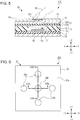
- FIG. 6 is an enlarged plan view of part of the in-vehicle input device 200.
- Figs. 7A and 7B are enlarged sectional views of parts of the in-vehicle input device 200.
- Fig. 7A is a sectional view of part including a first operation area 25b of the in-vehicle input device 200.
- FIG. 7B is a sectional view of part of the in-vehicle input device 200 in which the first operation area 25b is used as the first detecting unit and a second operation area 25c is used as the second detecting unit.
- Fig. 7A illustrates a section as viewed from the line VIIA-VIIA in Fig. 6 .
- Fig. 7B illustrates a section as viewed from the line VIIB-VIIB in Fig. 6 .
- the same components as those in the in-vehicle input device 100 are designated by the same reference numerals. A detailed description of these components is omitted.
- the in-vehicle input device 200 includes two touch panels 20 mounted on the right and left of the central part 60a of the steering wheel 60 of the vehicle such that the touch panels 20 are adjacent to the wheel part 60b, or so that the operator can easily operate the in-vehicle input device 200.
- the in-vehicle input device 200 has the same fundamental configuration as that of the in-vehicle input device 100, except for the first operation area 25b and the second operation areas 25c included in an operation surface 25a illustrated in Fig. 6 .
- each touch panel 20 includes an operation sheet 25 having an upper surface that includes the operation surface 25a.
- the operation surface 25a includes the first operation area 25b and the second operation areas 25c.
- the first operation area 25b is disposed at the middle of the operation surface 25a illustrated in Fig. 6
- the second operation areas 25c are arranged around the first operation area 25b.
- Each of the second operation areas 25c is disposed at a relatively short distance from the first operation area 25b.
- the second operation areas 25c are arranged on the right and left sides of the first operation area 25b and on the sides thereof farther from and closer to the operator such that each second operation area 25c is disposed at an angle of 90° from adjacent second operation areas 25c.
- the first operation area 25b and the second operation areas 25c each have a circular shape in this embodiment, these areas may have a rectangular shape, for example.
- the touch panel 20 includes, in sequence from top to bottom, the operation sheet 25, the suppression layer 14, the upper sheet 13 including the upper electrode 13a and the insulating layer 13b, a spacer 22, the lower sheet 11 including the lower electrode 11a, and the lower suppression layer 16 in the first operation area 25b and its vicinity.
- the touch panel 20 has the same arrangement in each of the second operation areas 25c and their vicinities.
- the spacer 22 is disposed between the lower sheet 11 and the upper electrode 13a.
- the spacer 22 includes an insulator 22c disposed between the lower sheet 11 and the upper electrode 13a.
- the spacer 22 has a first opening 22a disposed between the lower electrode 11a and the upper electrode 13a so as to coincide with the first operation area 25b in plan view and second openings 22b arranged between the lower electrode 11a and the upper electrode 13a so as to coincide with the second operation areas 25c in plan view.
- the first opening 22a is separated from the second openings 22b by the insulator 22c.
- the insulator 22c, the first opening 22a, and the second openings 22b of the spacer 22 are made in the same manner as that for the insulator 12b and the openings 12a of the spacer 12 in the in-vehicle input device 100.
- the first operation area 25b is used as the first detecting unit and each second operation area 25c is used as the second detecting unit such that any one of the second operation areas 25c is operated as the second detecting unit in a predetermined period of time that is relatively short, for example, 0.5 seconds, after an operation of the first operation area 25b as the first detecting unit.
- the second operation area 25c located farther from the operator (in the +Y direction) of the multiple second operation areas 25c is used.
- the operator presses the first operation area 25b in the operation surface 25a with the finger 65 to bring the upper electrode 13a into contact with the lower electrode 11a, thus performing a switch operation.
- the operator then slides the finger 65 on the operation surface 25a in the direction away from the operator (in the +Y direction) in, for example, 0.5 seconds, and presses the second operation area 25c located farther from the operator (in the +Y direction) in the operation surface 25a, thus changing a capacitance C2 between the lower electrode 11a and the upper electrode 13a.
- the in-vehicle input device 200 determines that a flick operation has been performed on the in-vehicle input device 200.
- the flick operation is an operation used for, for example, Japanese language input, and enables quick input of a target character or symbol. If the second operation area 25c is pressed in more than 0.5 seconds, for example, one second after pressing of the first operation area 25b, the in-vehicle input device 200 will determine that the first operation area 25b and the second operation area 25c have been operated individually, instead of determining that a flick operation has been performed.
- the second operation areas 25c are set to provide different operations.
- an operation associated with the operated second operation area 25c can be performed.
- Fig. 8 is an enlarged plan view of part of the in-vehicle input device 300.
- Fig. 9 is an enlarged sectional view of part of the in-vehicle input device 300.
- Fig. 9 illustrates a section as viewed from the line IX-IX in Fig. 8 .
- the same components as those in the in-vehicle input device 100 are designated by the same reference numerals. A detailed description of these components is omitted.
- the in-vehicle input device 300 includes two touch panels 30 mounted on the right and left of the central part 60a of the steering wheel 60 of the vehicle such that the touch panels 30 are adjacent to the wheel part 60b, or so that the operator can easily operate the in-vehicle input device 300.
- each touch panel 30 includes, in sequence from top to bottom, an operation sheet 35, the suppression layer 14, the upper sheet 13 including the upper electrode 13a and the insulating layer 13b, a spacer 32, the lower sheet 11 including the lower electrode 11a, and the lower suppression layer 16.
- the operation sheet 35 has an upper surface that includes an operation surface 35a.
- the operation surface 35a includes a plurality of third operation areas 35b arranged in directions closer to and away from the operator, or the Y direction.
- the adjacent third operation areas 35b are arranged at a relatively short distance from each other.
- the third operation areas 35b each have a rectangular shape having short sides extending in the Y direction in plan view in the present embodiment.
- each of the third operation areas 35b in the in-vehicle input device 300 is a protrusion 35c that protrudes upward from the operation surface 35a.
- the protrusion 35c may be formed by printing or applying soft resin, such as silicone resin, to the operation surface.
- the protrusion 35c may be formed such that a hole is formed in the operation sheet 35 and the hole is filled with a fluid to raise part of the operation sheet 35.
- the spacer 32 is disposed between the lower sheet 11 and the upper electrode 13a.
- the spacer 32 includes an insulator 32b disposed between the lower sheet 11 and the upper electrode 13a and has a plurality of third openings 32a arranged between the lower electrode 11a and the upper electrode 13a so as to coincide with the third operation areas 35b in plan view.
- the adjacent third openings 32a are separated from each other by the insulator 32b.
- the insulator 32b and the third openings 32a of the spacer 32 are made in the same manner as that for the insulator 12b and the openings 12a of the spacer 12 in the in-vehicle input device 100.
- the spacer 32 differs from the spacer 12 in the in-vehicle input device 100 in that each of the third openings 32a is filled with an elastic member 39 as illustrated in Fig. 9 .
- the elastic member 39 is made of soft resin.
- the viscosity of a material for the elastic member 39 is set so that a pressure applied to the third operation area 35b is transmitted through the operation sheet 35, the suppression layer 14, and the upper sheet 13 to appropriately curve and deform the upper electrode 13a.
- a capacitance C3 is formed in the elastic member 39 between the lower electrode 11a and the upper electrode 13a.
- the elastic member 39 functions as a dielectric, and thus allows the capacitance C3 to be greater than that in a configuration with no elastic member 39. Consequently, a change in the capacitance C3 can be greater than that in the configuration with no elastic member 39.
- the operator presses the center third operation area 35b of the multiple third operation areas 35b in Fig. 8 , or the center protrusion 35c with the finger 65 and then presses other third operation areas 35b while sliding the finger 65 in the direction away from the operator, or in the +Y direction.
- the operator may press the center third operation area 35b of the multiple third operation areas 35b with the finger 65 and then press other third operation areas 35b while sliding the finger 65 in the direction closer to the operator, or in the -Y direction.
- the operator sequentially applies a pressure to the multiple third operation areas 35b with the finger 65.
- the third operation areas 35b can be used for a high-speed slide operation.
- the third operation areas 35b can be used to quickly and continuously adjust the volume of the in-vehicle audio system.
- Each of the third openings 32a in the spacer 32 is filled with the elastic member 39. This enables a reduction in the length of each third opening 32a in the sliding direction, or the short side of the rectangular third opening 32a. Consequently, the length of the third operation area 35b in the sliding direction can be reduced.
- the in-vehicle input device 100 detects an input operation in response not to touching any of the touch panels 10 by the operator's finger 65, but to pressing any of the operation areas 15b by the finger 65. If the operator wears gloves, the operator can operate the in-vehicle input device 100.
- the suppression layer 14, which eliminates or reduces the formation of the capacitance C0 between the operator and the upper electrode 13a, can prevent an erroneous operation from being caused by unintended finger motion during driving.
- the operator can press the operation areas 15b of each touch panel 10 while rotating the steering wheel 60, and can thus perform an input operation regardless of an operation state of the steering wheel 60.
- the first detecting unit based on contact between the lower electrode 11a and the upper electrode 13a and the second detecting unit based on a change in the capacitance C0 between the lower electrode 11a and the upper electrode 13a, namely, the two different detecting units can be used differently based on the magnitude of a pressure applied to the operation area 15b.
- a switch operation for the first detecting unit and a slide operation for the second detecting unit can be combined. This facilitates various operations.
- the in-vehicle input device 200 detects a flick operation in response to an operation of any of the second operation areas 25c as the second detecting unit in a predetermined period of time after an operation of the first operation area 25b as the first detecting unit.
- a flick operation can be easily performed.
- each third operation area 35b is the protrusion 35c protruding upward from the operation surface 35a. This facilitates an operation in the third operation area 35b having the reduced length in the sliding direction. This also eliminates the need for viewing the touch panels 30, thus increasing the safety of driving.
- the in-vehicle input device 110 includes the contact member 19 in each operation area 15b and can thus be operated by lightly pressing any of the operation areas 15b. It is particularly effective when the operation area 15b is used as the first detecting unit that requires a greater pressure than the second detecting unit.
- the present invention is not limited to the above-described embodiments, but can be variously modified and practiced without departing from the scope of the invention.
- the contact member 19 is included in the modification of the in-vehicle input device 100 according to the first embodiment, the contact member 19 may be included in the in-vehicle input devices 200 and 300.
Landscapes
- Engineering & Computer Science (AREA)
- General Engineering & Computer Science (AREA)
- Theoretical Computer Science (AREA)
- Human Computer Interaction (AREA)
- Physics & Mathematics (AREA)
- General Physics & Mathematics (AREA)
- Chemical & Material Sciences (AREA)
- Combustion & Propulsion (AREA)
- Transportation (AREA)
- Mechanical Engineering (AREA)
- Push-Button Switches (AREA)
- Switches That Are Operated By Magnetic Or Electric Fields (AREA)
Claims (6)
- Fahrzeuginterne Eingabevorrichtung (100) für ein Lenkrad (60) eines Fahrzeugs, aufweisend:eine Berührungsplatte (10) mit einer unteren Elektrode (11a), einer oberen Elektrode (13a), die der unteren Elektrode (11a) zugewandt ist, und einem Abstandshalter (12), der zwischen der unteren Elektrode und der oberen Elektrode angeordnet ist;wobei die Vorrichtung (100) in der Lage ist, eine Kapazität (C0) zwischen der unteren Elektrode (11a) und der oberen Elektrode (13a) zu erfassen;wobei die Vorrichtung (100) eine Betätigungsfläche (15a) aufweist, die über der oberen Elektrode (13a) angeordnet ist, wobei die Betätigungsfläche (15a) eine Mehrzahl von Betätigungsbereichen (15b) aufweist,wobei der Abstandshalter (12) eine Mehrzahl von Öffnungen (12a) aufweist, die in der Draufsicht mit den Betätigungsbereichen übereinstimmen,wobei die Vorrichtung eine Eingabebetätigung auf der Basis einer Änderung des Abstands zwischen der unteren Elektrode (11a) und der oberen Elek - trode (13a) in Reaktion auf das Drücken eines beliebigen der Betätigungs - bereiche (15b) durch die Bedienungsperson erfasst;dadurch gekennzeichnet,dass die Vorrichtung ferner eine Unterdrückungsschicht (14) aufweist, die zwischen der Betätigungsfläche (15a) und der oberen Elektrode (13a) ange - ordnet ist oder auf einer oberen Oberfläche der Betätigungsfläche (15a) an - geordnet ist, wobei die Unterdrückungsschicht (14) das Bilden einer Kapazi - tät zwischen der oberen Elektrode (13a) und einer Bedienungsperson elimi - niert oder reduziert.
- Vorrichtung (100) nach Anspruch 1, die ferner aufweist:eine erste Erfassungseinrichtung zum Erfassen einer Eingabebetätigung auf der Basis eines Kontakts zwischen der unteren Elektrode (11a) und der oberen Elektrode (13a) in Reaktion auf das Drücken eines beliebigen der Betätigungsbereiche (15b) durch die Bedienungsperson; undeine zweite Erfassungseinrichtung zum Erfassen einer Eingabebetätigung auf der Basis einer Änderung der Kapazität, die durch eine Änderung des Abstands zwischen der unteren Elektrode (11a) und der oberen Elektrode (13a) in Reaktion auf das Drücken eines beliebigen der Betätigungsberei - che (15b) durch die Bedienungsperson verursacht ist.
- Vorrichtung (100) nach Anspruch 2,
wobei die erste Erfassungseinrichtung einen Schaltvorgang in dem Betäti - gungsbereich (15b) erfasst und die zweite Erfassungseinrichtung einen Ver - schiebevorgang (15b) in dem Betätigungsbereich erfasst. - Vorrichtung (100) nach Anspruch 3,
wobei die Betätigungsfläche (15a) einen ersten Betätigungsbereich (25b) und einen zweiten Betätigungsbereich (25c) aufweist und der Abstandshalter (12) eine erste Öffnung (22a) aufweist, die dem ersten Betätigungsbereich (25b) entspricht, sowie eine zweite Öffnung (22b) aufweist, die dem zweiten Betätigungsbereich (25c) entspricht, und
wobei die Vorrichtung (100) eine Schnipp-Betätigung in Reaktion auf eine Betätigung des zweiten Betätigungsbereichs (25c) als zweite Erfassungs-einrichtung in einem vorbestimmten Zeitraum nach einer Betätigung des ersten Betätigungsbereichs (25a) als erste Erfassungseinrichtung erfasst. - Vorrichtung (100) nach einem der Ansprüche 1 bis 3,
wobei die Betätigungsfläche (15a) eine Mehrzahl von dritten Betätigungsbereichen (35b) aufweist und der Abstandshalter (12) eine Mehrzahl von dritten Öffnungen (32a) aufweist, die den dritten Betätigungsbereichen (35b) entsprechen, und
wobei jede der dritten Öffnungen (32a) mit einem elastischen Element (39) gefüllt ist und jeder der dritten Bereiche ein Vorsprung (35c) ist, der von der Betätigungsfläche (15a) nach oben vorsteht. - Vorrichtung (100) nach einem der Ansprüche 1 bis 5, die ferner aufweist:
ein leitendes Kontaktelement (19), das auf mindestens einer der einander zugewandten Oberflächen der unteren und oberen Elektrode (11a, 13a) angeordnet ist, wobei das Kontaktelement (19) in jede der Öffnungen hineinragt.
Applications Claiming Priority (1)
| Application Number | Priority Date | Filing Date | Title |
|---|---|---|---|
| JP2015115486A JP6890372B2 (ja) | 2015-06-08 | 2015-06-08 | 車載入力装置 |
Publications (2)
| Publication Number | Publication Date |
|---|---|
| EP3104261A1 EP3104261A1 (de) | 2016-12-14 |
| EP3104261B1 true EP3104261B1 (de) | 2020-09-16 |
Family
ID=56134115
Family Applications (1)
| Application Number | Title | Priority Date | Filing Date |
|---|---|---|---|
| EP16173228.4A Active EP3104261B1 (de) | 2015-06-08 | 2016-06-07 | Fahrzeuginterne eingabevorrichtung |
Country Status (3)
| Country | Link |
|---|---|
| US (1) | US10095364B2 (de) |
| EP (1) | EP3104261B1 (de) |
| JP (1) | JP6890372B2 (de) |
Families Citing this family (8)
| Publication number | Priority date | Publication date | Assignee | Title |
|---|---|---|---|---|
| US11104229B2 (en) * | 2016-07-11 | 2021-08-31 | Shanghai Yanfeng Jinqiao Automotive Trim Systems Co. Ltd. | Vehicle interior component |
| CN106959772B (zh) * | 2017-03-28 | 2021-05-18 | 联想(北京)有限公司 | 一种输入方法及电子设备 |
| FR3066639A1 (fr) * | 2017-05-18 | 2018-11-23 | Delphi Technologies, Inc. | Ensemble de commande par contact glissant d'un panneau de commande pour vehicule automobile |
| KR102354135B1 (ko) * | 2017-10-12 | 2022-01-24 | 현대자동차주식회사 | 근접센서 |
| WO2020116500A1 (ja) * | 2018-12-04 | 2020-06-11 | 信越ポリマー株式会社 | 感圧タッチセンサ、感圧タッチセンサモジュール及び弾性電極シート |
| JP7422574B2 (ja) * | 2020-03-19 | 2024-01-26 | 信越ポリマー株式会社 | 感圧タッチセンサモジュール及び感圧タッチセンサ装置 |
| JP7652041B2 (ja) * | 2021-09-29 | 2025-03-27 | トヨタ自動車株式会社 | 車両用操作入力装置、車両用操作入力方法及びプログラム |
| TWI840013B (zh) * | 2022-03-10 | 2024-04-21 | 日商阿爾卑斯阿爾派股份有限公司 | 輸入裝置 |
Citations (2)
| Publication number | Priority date | Publication date | Assignee | Title |
|---|---|---|---|---|
| US5942733A (en) * | 1992-06-08 | 1999-08-24 | Synaptics, Inc. | Stylus input capacitive touchpad sensor |
| US20140267152A1 (en) * | 2013-03-12 | 2014-09-18 | Mircrochip Technology Incorporated | Force Sensing X-Y Touch Sensor |
Family Cites Families (23)
| Publication number | Priority date | Publication date | Assignee | Title |
|---|---|---|---|---|
| JP2000018905A (ja) | 1998-06-30 | 2000-01-21 | Nitta Ind Corp | 静電容量式センサ |
| JP2002225724A (ja) | 2001-01-30 | 2002-08-14 | Mitsubishi Motors Corp | 車載機器の操作装置 |
| US6809280B2 (en) * | 2002-05-02 | 2004-10-26 | 3M Innovative Properties Company | Pressure activated switch and touch panel |
| TWI271645B (en) * | 2005-04-19 | 2007-01-21 | Elan Microelectronics Corp | Capacitive touchpad with a physical key function |
| US8063886B2 (en) * | 2006-07-18 | 2011-11-22 | Iee International Electronics & Engineering S.A. | Data input device |
| JP4936323B2 (ja) * | 2006-11-09 | 2012-05-23 | 信越ポリマー株式会社 | 操作スイッチ用シート部材、操作スイッチ、及び操作スイッチ用シート部材の製造方法 |
| JP5370723B2 (ja) * | 2008-09-29 | 2013-12-18 | 株式会社ジャパンディスプレイ | 静電容量型入力装置、入力機能付き表示装置および電子機器 |
| JP5396335B2 (ja) * | 2009-05-28 | 2014-01-22 | 株式会社半導体エネルギー研究所 | タッチパネル |
| US8730199B2 (en) * | 2009-09-04 | 2014-05-20 | Atmel Corporation | Capacitive control panel |
| US20140063360A1 (en) * | 2010-06-17 | 2014-03-06 | Yousuke KUNISHI | Input device |
| US8735755B2 (en) * | 2011-03-07 | 2014-05-27 | Synaptics Incorporated | Capacitive keyswitch technologies |
| WO2012176748A1 (ja) * | 2011-06-24 | 2012-12-27 | 日本写真印刷株式会社 | 静電容量及び圧力の検出を併用した入力装置、及び感圧機能付き静電容量方式ハイブリッドタッチパネル |
| US9851884B2 (en) * | 2011-12-01 | 2017-12-26 | Panasonic Intellectual Property Management Co., Ltd. | Information processing device |
| JP2013149010A (ja) * | 2012-01-18 | 2013-08-01 | Alpine Electronics Inc | 車載機およびhtmlページ操作方法 |
| WO2013107474A1 (en) * | 2012-01-20 | 2013-07-25 | Sony Ericsson Mobile Communications Ab | Touch screen, portable electronic device, and method of operating a touch screen |
| JP6107811B2 (ja) * | 2012-03-09 | 2017-04-05 | ソニー株式会社 | センサ装置、入力装置及び電子機器 |
| US9058703B2 (en) * | 2012-03-14 | 2015-06-16 | Flextronics Ap, Llc | Shared navigational information between vehicles |
| JP6325576B2 (ja) * | 2013-01-17 | 2018-05-16 | マイクロチップ テクノロジー インコーポレイテッドMicrochip Technology Incorporated | 物理的力容量式タッチセンサ |
| JP6102646B2 (ja) * | 2013-01-23 | 2017-03-29 | ソニー株式会社 | 入力装置、電子機器及びセンサシート |
| JP6119518B2 (ja) * | 2013-02-12 | 2017-04-26 | ソニー株式会社 | センサ装置、入力装置及び電子機器 |
| CN107264283B (zh) * | 2013-03-29 | 2019-07-19 | 株式会社斯巴鲁 | 运输设备用显示装置 |
| JP2014229014A (ja) * | 2013-05-21 | 2014-12-08 | 日本精機株式会社 | タッチパネル入力操作装置 |
| JP2015195104A (ja) * | 2014-03-31 | 2015-11-05 | 株式会社ジャパンディスプレイ | 表示装置 |
-
2015
- 2015-06-08 JP JP2015115486A patent/JP6890372B2/ja active Active
-
2016
- 2016-05-27 US US15/167,416 patent/US10095364B2/en active Active
- 2016-06-07 EP EP16173228.4A patent/EP3104261B1/de active Active
Patent Citations (2)
| Publication number | Priority date | Publication date | Assignee | Title |
|---|---|---|---|---|
| US5942733A (en) * | 1992-06-08 | 1999-08-24 | Synaptics, Inc. | Stylus input capacitive touchpad sensor |
| US20140267152A1 (en) * | 2013-03-12 | 2014-09-18 | Mircrochip Technology Incorporated | Force Sensing X-Y Touch Sensor |
Also Published As
| Publication number | Publication date |
|---|---|
| US20160357287A1 (en) | 2016-12-08 |
| US10095364B2 (en) | 2018-10-09 |
| JP2017004136A (ja) | 2017-01-05 |
| EP3104261A1 (de) | 2016-12-14 |
| JP6890372B2 (ja) | 2021-06-18 |
Similar Documents
| Publication | Publication Date | Title |
|---|---|---|
| US10095364B2 (en) | In-vehicle input device | |
| US7312790B2 (en) | Input apparatus for performing input operation corresponding to indication marks and coordinate input operation on the same operational plane | |
| CN103226418B (zh) | 带按键开关的电容式触摸板 | |
| JP4749354B2 (ja) | タッチスイッチ構造 | |
| US9349551B2 (en) | Keyboard with elastic member disposed on touch panel | |
| KR101407850B1 (ko) | 입력 장치 | |
| US20100149104A1 (en) | Integrated keyboard and touchpad | |
| US9440536B2 (en) | Passenger vehicle with a modular control panel | |
| US20160170543A1 (en) | Detecting sensor and input device | |
| JP2008225821A (ja) | 入力装置 | |
| US20060001655A1 (en) | Light-transmitting touch panel and detection device | |
| CN105730320B (zh) | 开关装置 | |
| US20210247945A1 (en) | Operation device | |
| US11275477B2 (en) | Input device | |
| JP2012212240A (ja) | タッチパネルシステム | |
| JP2017088105A (ja) | スイッチ装置 | |
| JP2005078104A (ja) | タッチスイッチパネル | |
| US9124275B2 (en) | Touch panel | |
| JP6902635B2 (ja) | 車載入力装置 | |
| JP2006049271A (ja) | 光透過性タッチパネル及びこれを用いた検出装置 | |
| JP2006350789A (ja) | タッチパネル付き表示装置 | |
| JP4487757B2 (ja) | タッチパネル | |
| JP6473672B2 (ja) | 車載入力装置 | |
| KR102228053B1 (ko) | 3차원 포스 터치 센서 및 이를 이용한 표시 장치 | |
| KR102237838B1 (ko) | 터치 패널 |
Legal Events
| Date | Code | Title | Description |
|---|---|---|---|
| PUAI | Public reference made under article 153(3) epc to a published international application that has entered the european phase |
Free format text: ORIGINAL CODE: 0009012 |
|
| STAA | Information on the status of an ep patent application or granted ep patent |
Free format text: STATUS: THE APPLICATION HAS BEEN PUBLISHED |
|
| AK | Designated contracting states |
Kind code of ref document: A1 Designated state(s): AL AT BE BG CH CY CZ DE DK EE ES FI FR GB GR HR HU IE IS IT LI LT LU LV MC MK MT NL NO PL PT RO RS SE SI SK SM TR |
|
| AX | Request for extension of the european patent |
Extension state: BA ME |
|
| STAA | Information on the status of an ep patent application or granted ep patent |
Free format text: STATUS: REQUEST FOR EXAMINATION WAS MADE |
|
| 17P | Request for examination filed |
Effective date: 20170609 |
|
| RBV | Designated contracting states (corrected) |
Designated state(s): AL AT BE BG CH CY CZ DE DK EE ES FI FR GB GR HR HU IE IS IT LI LT LU LV MC MK MT NL NO PL PT RO RS SE SI SK SM TR |
|
| RAP1 | Party data changed (applicant data changed or rights of an application transferred) |
Owner name: ALPS ALPINE CO., LTD. |
|
| REG | Reference to a national code |
Ref country code: DE Ref legal event code: R079 Ref document number: 602016043997 Country of ref document: DE Free format text: PREVIOUS MAIN CLASS: G06F0003041000 Ipc: B60K0035000000 |
|
| GRAP | Despatch of communication of intention to grant a patent |
Free format text: ORIGINAL CODE: EPIDOSNIGR1 |
|
| STAA | Information on the status of an ep patent application or granted ep patent |
Free format text: STATUS: GRANT OF PATENT IS INTENDED |
|
| RIC1 | Information provided on ipc code assigned before grant |
Ipc: B60K 37/06 20060101ALI20200511BHEP Ipc: B60K 35/00 20060101AFI20200511BHEP Ipc: G06F 3/044 20060101ALI20200511BHEP |
|
| INTG | Intention to grant announced |
Effective date: 20200529 |
|
| GRAS | Grant fee paid |
Free format text: ORIGINAL CODE: EPIDOSNIGR3 |
|
| GRAA | (expected) grant |
Free format text: ORIGINAL CODE: 0009210 |
|
| STAA | Information on the status of an ep patent application or granted ep patent |
Free format text: STATUS: THE PATENT HAS BEEN GRANTED |
|
| AK | Designated contracting states |
Kind code of ref document: B1 Designated state(s): AL AT BE BG CH CY CZ DE DK EE ES FI FR GB GR HR HU IE IS IT LI LT LU LV MC MK MT NL NO PL PT RO RS SE SI SK SM TR |
|
| REG | Reference to a national code |
Ref country code: GB Ref legal event code: FG4D |
|
| REG | Reference to a national code |
Ref country code: CH Ref legal event code: EP |
|
| REG | Reference to a national code |
Ref country code: DE Ref legal event code: R096 Ref document number: 602016043997 Country of ref document: DE |
|
| REG | Reference to a national code |
Ref country code: IE Ref legal event code: FG4D |
|
| REG | Reference to a national code |
Ref country code: AT Ref legal event code: REF Ref document number: 1313858 Country of ref document: AT Kind code of ref document: T Effective date: 20201015 |
|
| PG25 | Lapsed in a contracting state [announced via postgrant information from national office to epo] |
Ref country code: BG Free format text: LAPSE BECAUSE OF FAILURE TO SUBMIT A TRANSLATION OF THE DESCRIPTION OR TO PAY THE FEE WITHIN THE PRESCRIBED TIME-LIMIT Effective date: 20201216 Ref country code: SE Free format text: LAPSE BECAUSE OF FAILURE TO SUBMIT A TRANSLATION OF THE DESCRIPTION OR TO PAY THE FEE WITHIN THE PRESCRIBED TIME-LIMIT Effective date: 20200916 Ref country code: NO Free format text: LAPSE BECAUSE OF FAILURE TO SUBMIT A TRANSLATION OF THE DESCRIPTION OR TO PAY THE FEE WITHIN THE PRESCRIBED TIME-LIMIT Effective date: 20201216 Ref country code: GR Free format text: LAPSE BECAUSE OF FAILURE TO SUBMIT A TRANSLATION OF THE DESCRIPTION OR TO PAY THE FEE WITHIN THE PRESCRIBED TIME-LIMIT Effective date: 20201217 Ref country code: FI Free format text: LAPSE BECAUSE OF FAILURE TO SUBMIT A TRANSLATION OF THE DESCRIPTION OR TO PAY THE FEE WITHIN THE PRESCRIBED TIME-LIMIT Effective date: 20200916 Ref country code: HR Free format text: LAPSE BECAUSE OF FAILURE TO SUBMIT A TRANSLATION OF THE DESCRIPTION OR TO PAY THE FEE WITHIN THE PRESCRIBED TIME-LIMIT Effective date: 20200916 |
|
| REG | Reference to a national code |
Ref country code: AT Ref legal event code: MK05 Ref document number: 1313858 Country of ref document: AT Kind code of ref document: T Effective date: 20200916 |
|
| REG | Reference to a national code |
Ref country code: NL Ref legal event code: MP Effective date: 20200916 |
|
| PG25 | Lapsed in a contracting state [announced via postgrant information from national office to epo] |
Ref country code: LV Free format text: LAPSE BECAUSE OF FAILURE TO SUBMIT A TRANSLATION OF THE DESCRIPTION OR TO PAY THE FEE WITHIN THE PRESCRIBED TIME-LIMIT Effective date: 20200916 Ref country code: RS Free format text: LAPSE BECAUSE OF FAILURE TO SUBMIT A TRANSLATION OF THE DESCRIPTION OR TO PAY THE FEE WITHIN THE PRESCRIBED TIME-LIMIT Effective date: 20200916 |
|
| REG | Reference to a national code |
Ref country code: LT Ref legal event code: MG4D |
|
| PG25 | Lapsed in a contracting state [announced via postgrant information from national office to epo] |
Ref country code: EE Free format text: LAPSE BECAUSE OF FAILURE TO SUBMIT A TRANSLATION OF THE DESCRIPTION OR TO PAY THE FEE WITHIN THE PRESCRIBED TIME-LIMIT Effective date: 20200916 Ref country code: CZ Free format text: LAPSE BECAUSE OF FAILURE TO SUBMIT A TRANSLATION OF THE DESCRIPTION OR TO PAY THE FEE WITHIN THE PRESCRIBED TIME-LIMIT Effective date: 20200916 Ref country code: SM Free format text: LAPSE BECAUSE OF FAILURE TO SUBMIT A TRANSLATION OF THE DESCRIPTION OR TO PAY THE FEE WITHIN THE PRESCRIBED TIME-LIMIT Effective date: 20200916 Ref country code: PT Free format text: LAPSE BECAUSE OF FAILURE TO SUBMIT A TRANSLATION OF THE DESCRIPTION OR TO PAY THE FEE WITHIN THE PRESCRIBED TIME-LIMIT Effective date: 20210118 Ref country code: RO Free format text: LAPSE BECAUSE OF FAILURE TO SUBMIT A TRANSLATION OF THE DESCRIPTION OR TO PAY THE FEE WITHIN THE PRESCRIBED TIME-LIMIT Effective date: 20200916 Ref country code: NL Free format text: LAPSE BECAUSE OF FAILURE TO SUBMIT A TRANSLATION OF THE DESCRIPTION OR TO PAY THE FEE WITHIN THE PRESCRIBED TIME-LIMIT Effective date: 20200916 Ref country code: LT Free format text: LAPSE BECAUSE OF FAILURE TO SUBMIT A TRANSLATION OF THE DESCRIPTION OR TO PAY THE FEE WITHIN THE PRESCRIBED TIME-LIMIT Effective date: 20200916 |
|
| PG25 | Lapsed in a contracting state [announced via postgrant information from national office to epo] |
Ref country code: ES Free format text: LAPSE BECAUSE OF FAILURE TO SUBMIT A TRANSLATION OF THE DESCRIPTION OR TO PAY THE FEE WITHIN THE PRESCRIBED TIME-LIMIT Effective date: 20200916 Ref country code: AT Free format text: LAPSE BECAUSE OF FAILURE TO SUBMIT A TRANSLATION OF THE DESCRIPTION OR TO PAY THE FEE WITHIN THE PRESCRIBED TIME-LIMIT Effective date: 20200916 Ref country code: AL Free format text: LAPSE BECAUSE OF FAILURE TO SUBMIT A TRANSLATION OF THE DESCRIPTION OR TO PAY THE FEE WITHIN THE PRESCRIBED TIME-LIMIT Effective date: 20200916 Ref country code: PL Free format text: LAPSE BECAUSE OF FAILURE TO SUBMIT A TRANSLATION OF THE DESCRIPTION OR TO PAY THE FEE WITHIN THE PRESCRIBED TIME-LIMIT Effective date: 20200916 Ref country code: IS Free format text: LAPSE BECAUSE OF FAILURE TO SUBMIT A TRANSLATION OF THE DESCRIPTION OR TO PAY THE FEE WITHIN THE PRESCRIBED TIME-LIMIT Effective date: 20210116 |
|
| REG | Reference to a national code |
Ref country code: DE Ref legal event code: R097 Ref document number: 602016043997 Country of ref document: DE |
|
| PG25 | Lapsed in a contracting state [announced via postgrant information from national office to epo] |
Ref country code: SK Free format text: LAPSE BECAUSE OF FAILURE TO SUBMIT A TRANSLATION OF THE DESCRIPTION OR TO PAY THE FEE WITHIN THE PRESCRIBED TIME-LIMIT Effective date: 20200916 |
|
| PLBE | No opposition filed within time limit |
Free format text: ORIGINAL CODE: 0009261 |
|
| STAA | Information on the status of an ep patent application or granted ep patent |
Free format text: STATUS: NO OPPOSITION FILED WITHIN TIME LIMIT |
|
| 26N | No opposition filed |
Effective date: 20210617 |
|
| PG25 | Lapsed in a contracting state [announced via postgrant information from national office to epo] |
Ref country code: DK Free format text: LAPSE BECAUSE OF FAILURE TO SUBMIT A TRANSLATION OF THE DESCRIPTION OR TO PAY THE FEE WITHIN THE PRESCRIBED TIME-LIMIT Effective date: 20200916 Ref country code: SI Free format text: LAPSE BECAUSE OF FAILURE TO SUBMIT A TRANSLATION OF THE DESCRIPTION OR TO PAY THE FEE WITHIN THE PRESCRIBED TIME-LIMIT Effective date: 20200916 |
|
| PG25 | Lapsed in a contracting state [announced via postgrant information from national office to epo] |
Ref country code: IT Free format text: LAPSE BECAUSE OF FAILURE TO SUBMIT A TRANSLATION OF THE DESCRIPTION OR TO PAY THE FEE WITHIN THE PRESCRIBED TIME-LIMIT Effective date: 20200916 |
|
| PG25 | Lapsed in a contracting state [announced via postgrant information from national office to epo] |
Ref country code: MC Free format text: LAPSE BECAUSE OF FAILURE TO SUBMIT A TRANSLATION OF THE DESCRIPTION OR TO PAY THE FEE WITHIN THE PRESCRIBED TIME-LIMIT Effective date: 20200916 |
|
| REG | Reference to a national code |
Ref country code: CH Ref legal event code: PL |
|
| REG | Reference to a national code |
Ref country code: BE Ref legal event code: MM Effective date: 20210630 |
|
| PG25 | Lapsed in a contracting state [announced via postgrant information from national office to epo] |
Ref country code: LU Free format text: LAPSE BECAUSE OF NON-PAYMENT OF DUE FEES Effective date: 20210607 |
|
| PG25 | Lapsed in a contracting state [announced via postgrant information from national office to epo] |
Ref country code: LI Free format text: LAPSE BECAUSE OF NON-PAYMENT OF DUE FEES Effective date: 20210630 Ref country code: IE Free format text: LAPSE BECAUSE OF NON-PAYMENT OF DUE FEES Effective date: 20210607 Ref country code: CH Free format text: LAPSE BECAUSE OF NON-PAYMENT OF DUE FEES Effective date: 20210630 |
|
| PG25 | Lapsed in a contracting state [announced via postgrant information from national office to epo] |
Ref country code: BE Free format text: LAPSE BECAUSE OF NON-PAYMENT OF DUE FEES Effective date: 20210630 |
|
| PG25 | Lapsed in a contracting state [announced via postgrant information from national office to epo] |
Ref country code: HU Free format text: LAPSE BECAUSE OF FAILURE TO SUBMIT A TRANSLATION OF THE DESCRIPTION OR TO PAY THE FEE WITHIN THE PRESCRIBED TIME-LIMIT; INVALID AB INITIO Effective date: 20160607 |
|
| PG25 | Lapsed in a contracting state [announced via postgrant information from national office to epo] |
Ref country code: CY Free format text: LAPSE BECAUSE OF FAILURE TO SUBMIT A TRANSLATION OF THE DESCRIPTION OR TO PAY THE FEE WITHIN THE PRESCRIBED TIME-LIMIT Effective date: 20200916 |
|
| PG25 | Lapsed in a contracting state [announced via postgrant information from national office to epo] |
Ref country code: MK Free format text: LAPSE BECAUSE OF FAILURE TO SUBMIT A TRANSLATION OF THE DESCRIPTION OR TO PAY THE FEE WITHIN THE PRESCRIBED TIME-LIMIT Effective date: 20200916 |
|
| PG25 | Lapsed in a contracting state [announced via postgrant information from national office to epo] |
Ref country code: MT Free format text: LAPSE BECAUSE OF FAILURE TO SUBMIT A TRANSLATION OF THE DESCRIPTION OR TO PAY THE FEE WITHIN THE PRESCRIBED TIME-LIMIT Effective date: 20200916 |
|
| PGFP | Annual fee paid to national office [announced via postgrant information from national office to epo] |
Ref country code: DE Payment date: 20250618 Year of fee payment: 10 |
|
| PGFP | Annual fee paid to national office [announced via postgrant information from national office to epo] |
Ref country code: GB Payment date: 20250618 Year of fee payment: 10 |
|
| PGFP | Annual fee paid to national office [announced via postgrant information from national office to epo] |
Ref country code: FR Payment date: 20250625 Year of fee payment: 10 |
|
| PG25 | Lapsed in a contracting state [announced via postgrant information from national office to epo] |
Ref country code: TR Free format text: LAPSE BECAUSE OF FAILURE TO SUBMIT A TRANSLATION OF THE DESCRIPTION OR TO PAY THE FEE WITHIN THE PRESCRIBED TIME-LIMIT Effective date: 20200916 |