EP3101351A1 - Temperaturregelungssystem - Google Patents
Temperaturregelungssystem Download PDFInfo
- Publication number
- EP3101351A1 EP3101351A1 EP15742724.6A EP15742724A EP3101351A1 EP 3101351 A1 EP3101351 A1 EP 3101351A1 EP 15742724 A EP15742724 A EP 15742724A EP 3101351 A1 EP3101351 A1 EP 3101351A1
- Authority
- EP
- European Patent Office
- Prior art keywords
- water
- unit
- header
- communication lines
- thermal valves
- Prior art date
- Legal status (The legal status is an assumption and is not a legal conclusion. Google has not performed a legal analysis and makes no representation as to the accuracy of the status listed.)
- Granted
Links
Images


Classifications
-
- F—MECHANICAL ENGINEERING; LIGHTING; HEATING; WEAPONS; BLASTING
- F24—HEATING; RANGES; VENTILATING
- F24D—DOMESTIC- OR SPACE-HEATING SYSTEMS, e.g. CENTRAL HEATING SYSTEMS; DOMESTIC HOT-WATER SUPPLY SYSTEMS; ELEMENTS OR COMPONENTS THEREFOR
- F24D15/00—Other domestic- or space-heating systems
- F24D15/04—Other domestic- or space-heating systems using heat pumps
-
- F—MECHANICAL ENGINEERING; LIGHTING; HEATING; WEAPONS; BLASTING
- F24—HEATING; RANGES; VENTILATING
- F24D—DOMESTIC- OR SPACE-HEATING SYSTEMS, e.g. CENTRAL HEATING SYSTEMS; DOMESTIC HOT-WATER SUPPLY SYSTEMS; ELEMENTS OR COMPONENTS THEREFOR
- F24D19/00—Details
- F24D19/10—Arrangement or mounting of control or safety devices
- F24D19/1006—Arrangement or mounting of control or safety devices for water heating systems
- F24D19/1009—Arrangement or mounting of control or safety devices for water heating systems for central heating
- F24D19/1039—Arrangement or mounting of control or safety devices for water heating systems for central heating the system uses a heat pump
-
- F—MECHANICAL ENGINEERING; LIGHTING; HEATING; WEAPONS; BLASTING
- F24—HEATING; RANGES; VENTILATING
- F24D—DOMESTIC- OR SPACE-HEATING SYSTEMS, e.g. CENTRAL HEATING SYSTEMS; DOMESTIC HOT-WATER SUPPLY SYSTEMS; ELEMENTS OR COMPONENTS THEREFOR
- F24D3/00—Hot-water central heating systems
- F24D3/18—Hot-water central heating systems using heat pumps
-
- F—MECHANICAL ENGINEERING; LIGHTING; HEATING; WEAPONS; BLASTING
- F24—HEATING; RANGES; VENTILATING
- F24F—AIR-CONDITIONING; AIR-HUMIDIFICATION; VENTILATION; USE OF AIR CURRENTS FOR SCREENING
- F24F5/00—Air-conditioning systems or apparatus not covered by F24F1/00 or F24F3/00, e.g. using solar heat or combined with household units such as an oven or water heater
- F24F5/0089—Systems using radiation from walls or panels
-
- F—MECHANICAL ENGINEERING; LIGHTING; HEATING; WEAPONS; BLASTING
- F25—REFRIGERATION OR COOLING; COMBINED HEATING AND REFRIGERATION SYSTEMS; HEAT PUMP SYSTEMS; MANUFACTURE OR STORAGE OF ICE; LIQUEFACTION SOLIDIFICATION OF GASES
- F25B—REFRIGERATION MACHINES, PLANTS OR SYSTEMS; COMBINED HEATING AND REFRIGERATION SYSTEMS; HEAT PUMP SYSTEMS
- F25B13/00—Compression machines, plants or systems, with reversible cycle
-
- F—MECHANICAL ENGINEERING; LIGHTING; HEATING; WEAPONS; BLASTING
- F24—HEATING; RANGES; VENTILATING
- F24D—DOMESTIC- OR SPACE-HEATING SYSTEMS, e.g. CENTRAL HEATING SYSTEMS; DOMESTIC HOT-WATER SUPPLY SYSTEMS; ELEMENTS OR COMPONENTS THEREFOR
- F24D2200/00—Heat sources or energy sources
- F24D2200/12—Heat pump
- F24D2200/123—Compression type heat pumps
-
- F—MECHANICAL ENGINEERING; LIGHTING; HEATING; WEAPONS; BLASTING
- F25—REFRIGERATION OR COOLING; COMBINED HEATING AND REFRIGERATION SYSTEMS; HEAT PUMP SYSTEMS; MANUFACTURE OR STORAGE OF ICE; LIQUEFACTION SOLIDIFICATION OF GASES
- F25B—REFRIGERATION MACHINES, PLANTS OR SYSTEMS; COMBINED HEATING AND REFRIGERATION SYSTEMS; HEAT PUMP SYSTEMS
- F25B2313/00—Compression machines, plants or systems with reversible cycle not otherwise provided for
- F25B2313/003—Indoor unit with water as a heat sink or heat source
-
- F—MECHANICAL ENGINEERING; LIGHTING; HEATING; WEAPONS; BLASTING
- F25—REFRIGERATION OR COOLING; COMBINED HEATING AND REFRIGERATION SYSTEMS; HEAT PUMP SYSTEMS; MANUFACTURE OR STORAGE OF ICE; LIQUEFACTION SOLIDIFICATION OF GASES
- F25B—REFRIGERATION MACHINES, PLANTS OR SYSTEMS; COMBINED HEATING AND REFRIGERATION SYSTEMS; HEAT PUMP SYSTEMS
- F25B2313/00—Compression machines, plants or systems with reversible cycle not otherwise provided for
- F25B2313/023—Compression machines, plants or systems with reversible cycle not otherwise provided for using multiple indoor units
- F25B2313/0233—Compression machines, plants or systems with reversible cycle not otherwise provided for using multiple indoor units in parallel arrangements
-
- F—MECHANICAL ENGINEERING; LIGHTING; HEATING; WEAPONS; BLASTING
- F25—REFRIGERATION OR COOLING; COMBINED HEATING AND REFRIGERATION SYSTEMS; HEAT PUMP SYSTEMS; MANUFACTURE OR STORAGE OF ICE; LIQUEFACTION SOLIDIFICATION OF GASES
- F25B—REFRIGERATION MACHINES, PLANTS OR SYSTEMS; COMBINED HEATING AND REFRIGERATION SYSTEMS; HEAT PUMP SYSTEMS
- F25B2339/00—Details of evaporators; Details of condensers
- F25B2339/04—Details of condensers
- F25B2339/047—Water-cooled condensers
-
- F—MECHANICAL ENGINEERING; LIGHTING; HEATING; WEAPONS; BLASTING
- F25—REFRIGERATION OR COOLING; COMBINED HEATING AND REFRIGERATION SYSTEMS; HEAT PUMP SYSTEMS; MANUFACTURE OR STORAGE OF ICE; LIQUEFACTION SOLIDIFICATION OF GASES
- F25B—REFRIGERATION MACHINES, PLANTS OR SYSTEMS; COMBINED HEATING AND REFRIGERATION SYSTEMS; HEAT PUMP SYSTEMS
- F25B2700/00—Sensing or detecting of parameters; Sensors therefor
- F25B2700/21—Temperatures
- F25B2700/2106—Temperatures of fresh outdoor air
-
- Y—GENERAL TAGGING OF NEW TECHNOLOGICAL DEVELOPMENTS; GENERAL TAGGING OF CROSS-SECTIONAL TECHNOLOGIES SPANNING OVER SEVERAL SECTIONS OF THE IPC; TECHNICAL SUBJECTS COVERED BY FORMER USPC CROSS-REFERENCE ART COLLECTIONS [XRACs] AND DIGESTS
- Y02—TECHNOLOGIES OR APPLICATIONS FOR MITIGATION OR ADAPTATION AGAINST CLIMATE CHANGE
- Y02B—CLIMATE CHANGE MITIGATION TECHNOLOGIES RELATED TO BUILDINGS, e.g. HOUSING, HOUSE APPLIANCES OR RELATED END-USER APPLICATIONS
- Y02B30/00—Energy efficient heating, ventilation or air conditioning [HVAC]
- Y02B30/12—Hot water central heating systems using heat pumps
Definitions
- the present invention relates to a temperature regulation system that carries out temperature regulation by supplying heating medium for objects of the temperature regulation.
- a hot water supply and heating apparatus disclosed in JP 2005-37019 A is a temperature regulation system that carries out temperature regulation by supplying heating medium for radiators provided in rooms and/or under floors.
- water is heated by heat exchange in a hot water supply heat exchanger for heat of combustion gas in a hot water supply burner.
- Connection ports are provided therein for supplying the produced hot water for a plurality of floor heating appliances installed in a building outside.
- supply of the hot water produced by the hot water supply heat exchanger to the floor heating appliances is commonly effected and stopped by a plurality of thermal valves provided in the hot water supply and heating apparatus in accordance with a number of the connection ports.
- the plurality of thermal valves that effect and stop the supply of the hot water produced by the hot water supply heat exchanger to the plurality of floor heating appliances are installed in the hot water supply and heating apparatus installed outdoors. Therefore, connection between the plurality of thermal valves installed on the outdoor hot water supply and heating apparatus and the indoor floor heating appliances has to be made by construction of a plurality of long pipes. A plurality of holes through which the plurality of pipes are to be respectively passed or a large hole through which the plurality of pipes are collectively passed has to be pierced in a wall of a house. Thus poor workability and increased costs make the problems.
- Temperature regulation systems as the following are conceivable in order to solve such a problem in the workability.
- a temperature regulation system is conceivable in which a hot water unit is provided separately from a heat source unit and in which a plurality of thermal valves are provided in the hot water unit.
- the temperature regulation system in which the hot water unit and the heat source unit are installed outdoors has problems similar to those of the hot water supply and heating apparatus disclosed in the cited document 1. Furthermore, the temperature regulation system in which only the hot water unit is installed indoors solves the problem in the workability but newly causes such problems as ensuring of an indoor space for installation of the hot water unit and noise control for pumps.
- a temperature regulation system is conceivable in which a heat source unit having a hot water unit built in and having a hot water unit controller is installed outdoors and in which a header unit having a plurality of thermal valves and a controller dedicated to the thermal valves is installed indoors.
- a temperature regulation system is conceivable in which a heat source unit having a hot water unit built in and having a hot water unit controller is installed outdoors and in which a plurality of thermal valves installed indoors are controlled by a dedicated controller installed indoors.
- the temperature regulation systems are required to be newly equipped with the controller dedicated to the thermal valves only for control over operation of above-mentioned thermal motor-actuated valves and communication and thus have a problem of cost increase.
- An object of the invention is to provide a temperature regulation system by which workability can be improved and which is inexpensive.
- a temperature regulation system of the invention comprises:
- walls therein encompasses walls provided between the rooms inside the building and a space outside the building, walls provided between the rooms inside the building and a space inside a garage or inside a warehouse, or the like, for instance.
- the water pipes that guide the hot water or the cold water produced by the water unit to the specified supply destinations and that guide the return water produced in the specified supply destinations to the water unit may be two water pipes that make connection of a supply water port and a return water port of the water unit to connection ports of the headers.
- controller that is provided in the water unit and that controls the opening-closing operations of the thermal valves is connected to the thermal valves through the communication lines.
- the water unit is installed outdoors and wherein the headers and the plurality of thermal valves are installed indoors.
- the water unit is installed outdoors while the headers and the plurality of thermal valves are installed indoors. Therefore, an exterior wall of the building is included in the walls interposed between the water unit and the headers.
- Quality of impressions of a house is dependent on exterior walls of the building thereof. Accordingly, the impressions of the house are degraded by an exterior wall of the building having a plurality of holes or a large hole through which a plurality of pipes are to be passed.
- the holes through which the two water pipes are to be passed have only to be pierced in the exterior wall of the building in the construction of the water unit and the headers, so that the reduction in the costs can be pursued and so that prevention of degradation in the impressions of the house with substantial improvement in the appearance of the building can be attained.
- a temperature regulation system in accordance with an embodiment further comprises a relay terminal that is provided in a header unit including the headers and the thermal valves and that intermediates the communication lines, wherein the communication lines are made of header-unit outside communication lines that are mainly placed outside the header unit and header-unit inside communication lines that are placed inside the header unit, and wherein the header-unit outside communication lines are connected to the header-unit inside communication lines through the relay terminal.
- the communication lines that make connection between the controller and the thermal valves are configured by connection between the header-unit outside communication lines and the header-unit inside communication lines through the relay terminal provided in the header unit. Provided that the relay terminal and the thermal valves are connected in advance through the header-unit-inside communication lines, therefore, there is no need to directly connect the header-unit-outside communication lines to the thermal valves in the construction of the water unit, so that the workability can further be improved.
- a temperature regulation system in accordance with an embodiment further comprises mechanical relays connected to the communication lines.
- the mechanical relays that resist generating noises are used rather than semiconductor relays that are prone to generate noises as relays to be connected to the communication lines and thus reduction in the noises can be pursued even if the communication lines have a long total length between 5 m and 20 m.
- the headers and the plurality of thermal valves are installed under indoor floors.
- headers and the plurality of thermal valves are installed under the floors where the floor cooling/heating panels connected to the headers and the thermal valves are installed, inside of the rooms can be made neat by shortening of piping for connection of the headers and the thermal valves to the floor cooling/heating panels and elimination of the header unit from the inside of the rooms.
- a temperature regulation system in accordance with an embodiment further comprises a heat source unit that produces heating medium having a high temperature or heating medium having a low temperature and that supplies the heating medium to the water unit, wherein the water unit is configured integrally with the heat source unit.
- the water unit that produces the hot water or the cold water is placed opposite to the headers having the plurality of thermal valves connected thereto with respect to the walls. Therefore, the water pipes that guide the hot water or the cold water produced by the water unit and the produced return water may be made of the two water pipes that make the connection of the supply water port and the return water port of the water unit to the connection ports of the headers.
- the holes through which the two water pipes are to be passed have only to be pierced in the walls interposed between the water unit and the headers.
- the improvement in the workability and the reduction in the costs can be attained.
- the appearance of the walls can substantially be improved.
- Fig. 1 is a representation illustrating a schematic configuration of a temperature regulation system in accordance with the embodiment.
- the temperature regulation system includes an outdoor unit 1, a water unit 2 connected to the outdoor unit 1, and a header unit 3 connected to the water unit 2.
- the outdoor unit 1 and the water unit 2 are installed outdoors, while the header unit 3 is installed indoors.
- the outdoor unit 1 includes a compressor 4, a four-way valve 5, an outdoor heat exchanger 6, an electric expansion valve 7, and an accumulator 8.
- One end side of the outdoor heat exchanger 6 is connected to one end side of the electric expansion valve 7.
- switching of the four-way valve 5 causes a suction side of the compressor 4 to be connected to the other end side of the outdoor heat exchanger 6 and causes a discharge side of the compressor 4 to be connected to one end side of a plate-type water heat exchanger 9.
- the suction side of the compressor 4 is connected to the one end side of the plate-type water heat exchanger 9 and the discharge side of the compressor 4 is connected to the other end side of the outdoor heat exchanger 6.
- the outdoor unit 1 includes first through third temperature sensors 10 through 12 that are made of thermistors, for instance, and an outdoor control device 13 that receives signals indicating temperatures detected by the first through third temperature sensors 10 through 12.
- the first temperature sensor 10 detects the temperature of refrigerant as the heating medium between the compressor 4 and the four-way valve 5.
- the second temperature sensor 11 is attached to the outdoor heat exchanger 6 and detects the temperature of the refrigerant in the outdoor heat exchanger 6.
- the third temperature sensor 12 is placed adjacent to the outdoor heat exchanger 6 and detects the temperature of outside air.
- the outdoor control device 13 controls an inverter (not illustrated) of the compressor 4 and an opening of the electric expansion valve 7 so that a heat exchange efficiency of the plate-type water heat exchanger 9 is optimized.
- the outdoor control device 13 is connected to a controller 14 of the water unit 2 through signal lines not illustrated.
- the outdoor heat exchanger 6, the compressor 4, the plate-type water heat exchanger 9, and the electric expansion valve 7 are connected in order of mention so as to form a refrigerant circuit.
- the water unit 2 is installed outdoors and includes the plate-type water heat exchanger 9, an expansion tank 15, and a circulation pump 16.
- the plate-type water heat exchanger 9 functions as a condenser or an evaporator for the refrigerant circuit.
- a channel through which the refrigerant from the outdoor unit 1 flows and a channel through which return water from floor cooling/heating panels 27, 28 installed indoors flows are provided in the plate-type water heat exchanger 9.
- a positive and negative pressure valve is attached to the expansion tank 15 and hot water or cold water from the plate-type water heat exchanger 9 is accumulated in the expansion tank 15.
- a water supply port 15a is provided on a top part of the expansion tank 15 so that the expansion tank 15 can be replenished with water through the water supply port 15a when the water is required.
- the floor cooling/heating panels 27, 28 are an example of the specified supply destinations.
- a suction side of the circulation pump 16 is connected to the expansion tank 15 and a discharge side of the circulation pump 16 is connected to a supply header 21 in the header unit 3.
- the circulation pump 16 is capable of delivering the hot water or the cold water, having undergone heat exchange with the refrigerant passing through the plate-type water heat exchanger 9, to the floor cooling/heating panels 27, 28 connected to the supply header 21.
- the water unit 2 includes first, second water temperature sensors 17, 18 each made of a thermistor, for instance, a refrigerant temperature sensor 19 made of a thermistor, for instance, a pressure sensor 20, and the controller 14.
- the first water temperature sensor 17 detects a temperature of the hot water or the cold water flowing from the plate-type water heat exchanger 9 toward the floor cooling/heating panels 27, 28.
- the second water temperature sensor 18 detects a temperature of the hot water or the cold water flowing from the floor cooling/heating panels 27, 28 toward the plate-type water heat exchanger 9.
- the refrigerant temperature sensor 19 detects a temperature of the refrigerant between the electric expansion valve 7 and the plate-type water heat exchanger 9.
- the pressure sensor 20 is placed adjacent to the plate-type water heat exchanger 9, detects a pressure of the refrigerant between the four-way valve 5 and the plate-type water heat exchanger 9, and transmits signals indicating the pressure to the controller 14.
- the controller 14 transmits signals, indicating setting temperatures for the floor cooling/heating panels 27, 28, or the like to the outdoor control device 13.
- the controller 14 controls the circulation pump 16, first through fourth thermal valves 23 through 26, and the like based on designation signals from the outdoor control device 13, the temperatures of the hot water or the cold water detected by the first, second water temperature sensors 17, 18, and/or the like.
- the header unit 3 is installed indoors and includes the supply header 21 and a return header 22.
- One end of each of the first through fourth thermal valves 23 through 26 is connected to the supply header 21.
- Water inlets of the first and second floor cooling/heating panels 27 and 28 are respectively connected to the other ends of the first and second thermal valves 23 and 24.
- Water outlets of the first and second floor cooling/heating panels 27 and 28 are connected to the return header 22.
- the first and second floor cooling/heating panels 27 and 28 respectively include water circulation pipes 30 and 31 that are each formed in a meandering shape and that are supplied with the hot water or the cold water from the plate-type water heat exchanger 9.
- a remote control 32 for setting of the temperatures of the first and second floor cooling/heating panels 27, 28 and the like is provided indoors and connection between the remote control 32 and the controller 14 of the water unit 2 is made by a communication line 33.
- a relay terminal 34 is provided in a header box (not illustrated) that is placed in the header unit 3 and that houses the supply header 21, the return header 22, and the first through fourth thermal valves 23 through 26 and connection between four internal terminals (not illustrated) in the relay terminal 34 and drive units for the first through fourth thermal valves 23 through 26 is made by header-unit-inside communication lines 35. Connection between the internal terminals in the relay terminal 34 and the controller 14 of the water unit 2 is made by header-unit-outside communication lines 36.
- connection between the relay terminal 34 and the drive units for the first through fourth thermal valves 23 through 26 that are provided in the header box is made in advance by the header-unit-inside communication lines 35 in such a configuration, there is no need to directly connect the header-unit-outside communication lines 36 to the drive units for the first through fourth thermal valves 23 through 26 in construction of the outdoor unit 1 and the water unit 2, so that workability can be improved.
- noises might be produced by use of semiconductor relays such as SSR (Solid State Relay) as relays that are used for the header-unit inside communication lines 35 and the header-unit outside communication lines 36 because the communication lines 34, 35 have a long total length between 5 m and 20 m.
- SSR Solid State Relay
- the temperature regulation system operates as follows.
- the refrigerant discharged from the compressor 4 passes through the four-way valve 5 and flows into the plate-type water heat exchanger 9. That is, the refrigerant having a high temperature and a high pressure is supplied to the plate-type water heat exchanger 9.
- the refrigerant condensed and having a low temperature and a high pressure as a result of heat exchange with the water in the plate-type water heat exchanger 9 is expanded to be decompressed by the electric expansion valve 7, absorbs heat from outdoor air so as to be evaporated in the outdoor heat exchanger 6, thereafter passes through the four-way valve 5 and the accumulator 8, and returns to the compressor 4. Then the water flowing through the plate-type water heat exchanger 9 is turned into hot water by the heat exchange with the refrigerant and flows toward the first and second floor cooling/heating panels 27 and 28.
- the controller 14 controls on-off operation for the first and second thermal valves 23 and 24 in cooperation with the outdoor control device 13 of the outdoor unit 1 so that the first and second floor cooling/heating panel 27 and 28 have the preset temperatures.
- the refrigerant discharged from the compressor 4 passes through the four-way valve 5, is supplied to the outdoor heat exchanger 6, and is condensed in process of heat exchange with the outdoor air.
- the condensed refrigerant is decompressed by the electric expansion valve 7 and flows into the plate-type water heat exchanger 9. That is, the refrigerant having a low temperature and a low pressure is supplied to the plate-type water heat exchanger 9.
- the refrigerant having absorbed heat from the water and having been evaporated in the plate-type water heat exchanger 9 passes through the four-way valve 5 and the accumulator 8 and returns to the compressor 4. Then the water flowing through the plate-type water heat exchanger 9 is turned into cold water by heat exchange with the refrigerant and flows toward the first and second floor cooling/heating panels 27 and 28.
- the controller 14 controls the on-off operation for the first and second thermal valves 23 and 24 in cooperation with the outdoor control device 13 of the outdoor unit 1 so that the first and second floor cooling/heating panel 27 and 28 have the setting temperatures.
- the water unit 2 is installed outdoors and the header unit 3 is installed indoors as described above.
- the supply header 21 to which the first through fourth thermal valves 23 through 26 are connected and the return header 22 are provided in the header unit 3.
- the controller 14 that exerts on-off control over the first through fourth thermal valves 23 through 26 is provided in the water unit 2.
- supply of the hot water or the cold water from the water unit 2 to the first through fourth thermal valves 23 through 26 has only to be carried out solely through one system to a connection port 21a of the supply header 21.
- return of the water from the first through fourth thermal valves 23 through 26 to the water unit 2 has only to be carried out solely through one system from a connection port 22a of the return header 22.
- Fig. 2 is a representation illustrating an overall configuration of the water unit 2.
- the water unit 2 includes a parallelepiped casing 41, the circulation pump 16 that is attached and fixed to a bottom frame 41a of the casing 41, and the plate-type water heat exchanger 9 placed adjacent to a side face frame 41b of the casing 41.
- a first refrigerant pipe 42 for supplying or discharging the refrigerant from the compressor 4 and a second refrigerant pipe 43 for discharging or supplying the refrigerant.
- a first water feeding pipe 44 for feeding the water to the circulation pump 16 and one end of a second water feeding pipe 45 for returning the water from the return header 22.
- the other end of the first water feeding pipe 44 is connected to a suction port of the circulation pump 16 and one end of a discharge pipe 46 is connected to a discharge port of the circulation pump 16.
- a return water port 48 is connected to the other end of the second water feeding pipe 45.
- a supply water port 51 is connected to the other end of the discharge pipe 46.
- the supply of the hot water or the cold water from the water unit 2 to the first through fourth thermal valves 23 through 26 is thus carried out through one first water pipe 52 that makes connection between the supply water port 51 of the water unit 2 and the connection port 21a of the supply header 21 as illustrated in Fig. 1 .
- the return of the water from the first and second floor cooling/heating panels 27 and 28 to the water unit 2 is carried out through one second water pipe 53 that makes connection between the connection port 22a of the return header 22 and the return water port 48 of the water unit 2.
- two holes through which the two water pipes, namely, the first water pipe 52 for supply and the second water pipe 53 for return are to be respectively passed or a hole through which the two water pipes are to be collectively passed and a small hole through which the thin communication line 33 that makes the connection between the remote control 32 and the controller 14 of the water unit 2 is to be passed have only to be pierced in a wall of a building, so that improvement in the workability and reduction in costs can be attained. In addition, appearance of the building can substantially be improved.
- a diameter of the hole pierced in the wall of the building can be decreased in comparison with a configuration in which the first through fourth thermal valves 23 through 26 are installed outdoors. Accordingly, the workability and the appearance of the building can be improved.
- connection between the controller 14 in the water unit 2 and the first through fourth thermal valves 23 through 26 in the header unit 3 is made by the header-unit inside communication lines 35 and the header-unit outside communication lines 36 with the relay terminal 34 provided in the header box between.
- the header-unit-outside communication lines 36 are respectively and directly connected to the drive units for the first through fourth thermal valves 23 through 26, so that the workability can further be improved.
- the mechanical relays that resist generating noises are used rather than semiconductor relays that are prone to generate noises.
- the reduction in the noises can be pursued even if the communication lines 34 and 35 have a long total length between 5 m and 20 m.
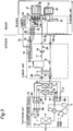
- Fig. 3 is a representation illustrating a schematic configuration of a temperature regulation system that is further capable of cooling and heating inside of rooms.
- Members in Fig. 3 that are the same as those in Fig. 1 are provided with the same reference characters and detailed description thereon is omitted.
- the modification includes first and second indoor heat exchangers 61 and 62 connected to the outdoor unit 1, in addition to the outdoor unit 1, the water unit 2 connected to the outdoor unit 1, and the header unit 3 connected to the water unit 2.
- the first indoor heat exchanger 61 has one end connected through a first electric expansion valve 63 to the outdoor heat exchanger 6 and has the other end connected to the four-way valve 5.
- the second indoor heat exchanger 62 has one end connected through a second electric expansion valve 64 to the outdoor heat exchanger 6 and has the other end connected to the four-way valve 5.
- the modification further includes a fourth temperature sensor 65 that detects a temperature of the refrigerant between the electric expansion valve 7 and the plate-type water heat exchanger 9, a fifth temperature sensor 66 that detects a temperature of the refrigerant between the first electric expansion valve 63 and the first indoor heat exchanger 61, and a sixth temperature sensor 67 that detects a temperature of the refrigerant between the second electric expansion valve 64 and the second indoor heat exchanger 62.
- the modification further includes a seventh temperature sensor 68 that detects a temperature of the refrigerant between the four-way valve 5 and the plate-type water heat exchanger 9, an eighth temperature sensor 69 that detects a temperature of the refrigerant between the four-way valve 5 and the first indoor heat exchanger 61, and a ninth temperature sensor 70 that detects a temperature of the refrigerant between the four-way valve 5 and the second indoor heat exchanger 62.
- a tenth temperature sensor 71 that detects a temperature of the refrigerant in the first indoor heat exchanger 61 is attached to the first indoor heat exchanger 61.
- An eleventh temperature sensor 72 that detects a temperature of a room is provided adjacent to the first indoor heat exchanger 61.
- a twelfth temperature sensor 73 that detects a temperature of the refrigerant in the second indoor heat exchanger 62 is attached to the second indoor heat exchanger 62.
- a thirteenth temperature sensor 74 that detects a temperature of a room is provided adjacent to the second indoor heat exchanger 62.
- the outdoor control device 13 controls the inverter (not illustrated) of the compressor 4 and controls the opening of the electric expansion valve 7 and openings of the first and second electric expansion valves 63 and 64 so that the heat exchange efficiency of the plate-type water heat exchanger 9 and heat exchange efficiencies of the first and second indoor heat exchangers 61 and 62 are optimized.
- the temperature regulation system operates as follows.
- the refrigerant discharged from the compressor 4 passes through the four-way valve 5 and then a portion of the refrigerant flows into the plate-type water heat exchanger 9 while the remaining portion of the refrigerant flows into the first and second indoor heat exchangers 61 and 62.
- the refrigerant condensed as a result of heat exchange with indoor air in the first and second indoor heat exchangers 61 and 62 is expanded to be decompressed by the first and second electric expansion valves 63 and 64, absorbs heat from outdoor air so as to be evaporated in the outdoor heat exchanger 6, thereafter passes through the four-way valve 5 and the accumulator 8, and returns to the compressor 4.
- the refrigerant discharged from the compressor 4 passes through the four-way valve 5, is supplied to the outdoor heat exchanger 6, and is condensed in process of heat exchange with the outdoor air.
- a portion of the condensed refrigerant is decompressed by the electric expansion valve 7 and flows into the plate-type water heat exchanger 9, while the remaining portion of the condensed refrigerant is decompressed by the first and second electric expansion valves 63 and 64 and flows into the first and second indoor heat exchangers 61 and 62.
- the refrigerant having absorbed heat from the indoor air and having been evaporated in the first and second indoor heat exchangers 61 and 62 passes through the four-way valve 5 and the accumulator 8 and returns to the compressor 4.
- cooling/heating of inside of the rooms by the first and second indoor heat exchangers 61 and 62 and floor cooling/heating by the plate-type water heat exchanger 9 thus can be performed in parallel.
- the outdoor unit 1 and the water unit 2 are separately configured in the embodiment and the modification thereto, there is no harm in integrally configuring the outdoor unit 1 and the water unit 2.
- the latter configuration removes necessity of plumbing and cabling work between the outdoor unit 1 and the water unit 2 and thus further improvement in the workability can be pursued.
- the header unit 3 is preferably installed under either of floors where the first and second floor cooling/heating panels 27 and 28 connected to the first through fourth thermal valves 23 through 26 and the return header 22 are installed.
- the inside of the rooms can be made neat by shortening of piping for connection of the first and second thermal valves 23 and 24 and the return header 22 to the first and second floor cooling/heating panels 27 and 28 and by elimination of the header unit 3 from the inside of the rooms.
- the first through fourth thermal valves 23 through 26 are connected to the supply header 21 while the water outlets of the first and second floor cooling/heating panels 27 and 28 are connected to the return header 22.
- the invention is not limited thereto and there is no harm in connecting the water inlets of the first and second floor cooling/heating panels 27 and 28 to the supply header 21 and connecting the first through fourth thermal valves 23 through 26 to the return header 22.
- the water unit 2 is installed outdoors.
- the water unit 2, however, is not necessarily installed outdoors.
- the water unit 2 can be installed in a parking space, a basement, a closet, or the like, for instance, which is separated by walls from the rooms in the building where the first and second floor cooling/heating panels 27 and 28 are installed in order that the return water which flows from the first and second floor cooling/heating panels 27 and 28 to the water unit 2 through the second water pipe 53 in the water circuit 29 may be prevented from freezing.
- two holes through which two refrigerant pipes, namely, a refrigerant channel connecting the electric expansion valve 7 and the plate-type water heat exchanger 9 and a refrigerant channel connecting the four-way valve 5 and the plate-type water heat exchanger 9 are to be respectively passed or a hole through which the two refrigerant pipes are to be collectively passed has only to be pierced in a wall of the building, so that the improvement in the workability and the reduction in the costs can be attained.
- the appearance of the building can substantially be improved.
- two holes through which the two water pipes, namely, the first water pipe 52 for supply and the second water pipe 53 for return are to be respectively passed or a hole through which the two water pipes are to be collectively passed and a small hole through which the thin communication line 33 that makes the connection between the remote control 32 and the controller 14 of the water unit 2 is to be passed have only to be pierced in walls that provide partition between the rooms where the first and second floor cooling/heating panels 27 and 28 are installed and the room where the water unit 2 is installed, so that the improvement in the workability and the reduction in the costs can be attained.
- appearance of the walls that provide the partition between the rooms can substantially be improved.
- At least one of the floor cooling/heating panels 27 and 28 may be replaced by heat exchange terminals such as ceiling cooling/heating panels, ceiling cooling panels, ceiling heating panels, wall cooling/heating panels, wall cooling panels, wall heating panels, and indoor installed radiators. That is, heat exchange terminals such as ceiling cooling/heating panels, ceiling cooling panels, ceiling heating panels, wall cooling/heating panels, wall cooling panels, wall heating panels, and indoor installed radiators can be enumerated as another example of the specified supply destinations.
Landscapes
- Engineering & Computer Science (AREA)
- Mechanical Engineering (AREA)
- General Engineering & Computer Science (AREA)
- Chemical & Material Sciences (AREA)
- Combustion & Propulsion (AREA)
- Physics & Mathematics (AREA)
- Thermal Sciences (AREA)
- Life Sciences & Earth Sciences (AREA)
- Sustainable Development (AREA)
- Steam Or Hot-Water Central Heating Systems (AREA)
- Other Air-Conditioning Systems (AREA)
- Air Conditioning Control Device (AREA)
Applications Claiming Priority (2)
| Application Number | Priority Date | Filing Date | Title |
|---|---|---|---|
| JP2014017558 | 2014-01-31 | ||
| PCT/JP2015/052557 WO2015115560A1 (ja) | 2014-01-31 | 2015-01-29 | 温調システム |
Publications (4)
| Publication Number | Publication Date |
|---|---|
| EP3101351A1 true EP3101351A1 (de) | 2016-12-07 |
| EP3101351A8 EP3101351A8 (de) | 2017-02-15 |
| EP3101351A4 EP3101351A4 (de) | 2017-12-27 |
| EP3101351B1 EP3101351B1 (de) | 2019-03-06 |
Family
ID=53757130
Family Applications (1)
| Application Number | Title | Priority Date | Filing Date |
|---|---|---|---|
| EP15742724.6A Active EP3101351B1 (de) | 2014-01-31 | 2015-01-29 | Temperaturregelungssystem |
Country Status (3)
| Country | Link |
|---|---|
| EP (1) | EP3101351B1 (de) |
| JP (1) | JP5892269B2 (de) |
| WO (1) | WO2015115560A1 (de) |
Cited By (5)
| Publication number | Priority date | Publication date | Assignee | Title |
|---|---|---|---|---|
| CN108592140A (zh) * | 2018-05-08 | 2018-09-28 | 南京酷朗电子有限公司 | 降低供热管路回水温度的系统 |
| CN111758007A (zh) * | 2018-02-28 | 2020-10-09 | 三菱电机株式会社 | 空调装置 |
| DE102019119229A1 (de) * | 2019-07-16 | 2021-01-21 | Vaillant Gmbh | Sicherheitsablass einer Wärmepumpenaußeneinheit |
| DE102019119243A1 (de) * | 2019-07-16 | 2021-01-21 | Vaillant Gmbh | Sicherheitsablass einer Wärmepumpenaußeneinheit |
| EP4124801A1 (de) * | 2021-07-26 | 2023-02-01 | LG Electronics Inc. | Wärmezufuhrvorrichtung |
Families Citing this family (1)
| Publication number | Priority date | Publication date | Assignee | Title |
|---|---|---|---|---|
| US20250027659A1 (en) * | 2021-12-23 | 2025-01-23 | Mitsubishi Electric Corporation | Heat pump apparatus |
Family Cites Families (9)
| Publication number | Priority date | Publication date | Assignee | Title |
|---|---|---|---|---|
| JPH10196974A (ja) * | 1996-12-27 | 1998-07-31 | Tokyo Gas Co Ltd | 床暖房システム |
| JP2000266359A (ja) * | 1999-03-17 | 2000-09-29 | Tokyo Gas Co Ltd | 給水・給湯システム |
| JP2001336787A (ja) * | 2000-05-31 | 2001-12-07 | Daikin Ind Ltd | 温調装置 |
| JP4017438B2 (ja) * | 2002-04-25 | 2007-12-05 | 三洋電機株式会社 | 温水床暖房システム |
| JP2004205200A (ja) * | 2002-12-10 | 2004-07-22 | Sanyo Electric Co Ltd | ヒートポンプ式温水暖房装置 |
| JP2005037019A (ja) | 2003-07-18 | 2005-02-10 | Paloma Ind Ltd | 給湯暖房機 |
| JP2008123649A (ja) * | 2006-11-15 | 2008-05-29 | Funai Electric Co Ltd | 録画再生装置 |
| JP2012189250A (ja) * | 2011-03-10 | 2012-10-04 | Corona Corp | ヒートポンプ式温水暖房装置 |
| JP5594278B2 (ja) * | 2011-11-18 | 2014-09-24 | ダイキン工業株式会社 | 床暖房システム |
-
2015
- 2015-01-28 JP JP2015014681A patent/JP5892269B2/ja active Active
- 2015-01-29 EP EP15742724.6A patent/EP3101351B1/de active Active
- 2015-01-29 WO PCT/JP2015/052557 patent/WO2015115560A1/ja not_active Ceased
Cited By (7)
| Publication number | Priority date | Publication date | Assignee | Title |
|---|---|---|---|---|
| CN111758007A (zh) * | 2018-02-28 | 2020-10-09 | 三菱电机株式会社 | 空调装置 |
| EP3760936A4 (de) * | 2018-02-28 | 2021-03-10 | Mitsubishi Electric Corporation | Klimatisierungsvorrichtung |
| US11326788B2 (en) * | 2018-02-28 | 2022-05-10 | Mitsubishi Electric Corporation | Air-conditioning apparatus |
| CN108592140A (zh) * | 2018-05-08 | 2018-09-28 | 南京酷朗电子有限公司 | 降低供热管路回水温度的系统 |
| DE102019119229A1 (de) * | 2019-07-16 | 2021-01-21 | Vaillant Gmbh | Sicherheitsablass einer Wärmepumpenaußeneinheit |
| DE102019119243A1 (de) * | 2019-07-16 | 2021-01-21 | Vaillant Gmbh | Sicherheitsablass einer Wärmepumpenaußeneinheit |
| EP4124801A1 (de) * | 2021-07-26 | 2023-02-01 | LG Electronics Inc. | Wärmezufuhrvorrichtung |
Also Published As
| Publication number | Publication date |
|---|---|
| EP3101351A4 (de) | 2017-12-27 |
| WO2015115560A1 (ja) | 2015-08-06 |
| JP5892269B2 (ja) | 2016-03-23 |
| EP3101351B1 (de) | 2019-03-06 |
| EP3101351A8 (de) | 2017-02-15 |
| JP2015163834A (ja) | 2015-09-10 |
Similar Documents
| Publication | Publication Date | Title |
|---|---|---|
| EP3101351B1 (de) | Temperaturregelungssystem | |
| US10962267B2 (en) | Heat pump apparatus | |
| US9310106B2 (en) | Heat pump system | |
| US9927133B2 (en) | Air conditioning system | |
| US20090188985A1 (en) | Combined chiller and boiler HVAC system in a single outdoor operating unit | |
| US9557067B2 (en) | Air conditioning system with heat pump section and separate heat source section | |
| US20150276255A1 (en) | Air conditioning apparatus | |
| US12173909B2 (en) | Integrated space conditioning and water heating/cooling systems and methods thereto | |
| EP3358273B1 (de) | Nutzungsvorrichtung für wärmepumpe | |
| WO2005106346A1 (ja) | ヒートポンプ式給湯装置 | |
| KR20030084686A (ko) | 히트 펌프식 온수 난방 장치 | |
| JP2008281319A (ja) | 空調室外機接続型冷温水式床冷暖房ユニット | |
| US11796222B2 (en) | Wall mounted, concealed, water-to-water, water source heat pump with domestic hot water heat exchanger and storage tank | |
| US10578345B2 (en) | Heat transfer and hydronic systems | |
| JP6250195B2 (ja) | 蓄熱空調システム | |
| US20240044546A1 (en) | Water-to-water, water source heat pump with domestic hot water heat priority refrigeration circuit | |
| WO2025094096A1 (en) | Heat pump module for a hybrid heating apparatus and related apparatus | |
| JP2014163536A (ja) | 温調システム | |
| JP6666803B2 (ja) | 温水暖房システム | |
| JP2017120141A (ja) | 空気調和機および除霜補助装置 | |
| EP2017538A2 (de) | Klimaanlagensystem für ein Wohnhaus | |
| EP2034248A1 (de) | Wärmepumpen-heisswasserversorgungssystem | |
| CN101089519A (zh) | 制冷采暖与热水供应系统 |
Legal Events
| Date | Code | Title | Description |
|---|---|---|---|
| PUAI | Public reference made under article 153(3) epc to a published international application that has entered the european phase |
Free format text: ORIGINAL CODE: 0009012 |
|
| STAA | Information on the status of an ep patent application or granted ep patent |
Free format text: STATUS: REQUEST FOR EXAMINATION WAS MADE |
|
| 17P | Request for examination filed |
Effective date: 20160719 |
|
| AK | Designated contracting states |
Kind code of ref document: A1 Designated state(s): AL AT BE BG CH CY CZ DE DK EE ES FI FR GB GR HR HU IE IS IT LI LT LU LV MC MK MT NL NO PL PT RO RS SE SI SK SM TR |
|
| AX | Request for extension of the european patent |
Extension state: BA ME |
|
| RIN1 | Information on inventor provided before grant (corrected) |
Inventor name: HIROSE, JUNICHI Inventor name: YOSHIKAWA, SHINJI Inventor name: NISHIDA, TERUO |
|
| DAX | Request for extension of the european patent (deleted) | ||
| A4 | Supplementary search report drawn up and despatched |
Effective date: 20171123 |
|
| RIC1 | Information provided on ipc code assigned before grant |
Ipc: F24D 15/04 20060101ALI20171117BHEP Ipc: F24F 5/00 20060101ALI20171117BHEP Ipc: F24D 19/10 20060101ALI20171117BHEP Ipc: F24D 3/18 20060101AFI20171117BHEP Ipc: F25B 13/00 20060101ALI20171117BHEP |
|
| REG | Reference to a national code |
Ref country code: DE Ref legal event code: R079 Ref document number: 602015025879 Country of ref document: DE Free format text: PREVIOUS MAIN CLASS: F24D0003000000 Ipc: F24D0003180000 |
|
| GRAP | Despatch of communication of intention to grant a patent |
Free format text: ORIGINAL CODE: EPIDOSNIGR1 |
|
| STAA | Information on the status of an ep patent application or granted ep patent |
Free format text: STATUS: GRANT OF PATENT IS INTENDED |
|
| RIC1 | Information provided on ipc code assigned before grant |
Ipc: F24D 15/04 20060101ALI20180831BHEP Ipc: F25B 13/00 20060101ALI20180831BHEP Ipc: F24D 3/18 20060101AFI20180831BHEP Ipc: F24D 19/10 20060101ALI20180831BHEP Ipc: F24F 5/00 20060101ALI20180831BHEP |
|
| INTG | Intention to grant announced |
Effective date: 20180918 |
|
| GRAS | Grant fee paid |
Free format text: ORIGINAL CODE: EPIDOSNIGR3 |
|
| GRAA | (expected) grant |
Free format text: ORIGINAL CODE: 0009210 |
|
| STAA | Information on the status of an ep patent application or granted ep patent |
Free format text: STATUS: THE PATENT HAS BEEN GRANTED |
|
| AK | Designated contracting states |
Kind code of ref document: B1 Designated state(s): AL AT BE BG CH CY CZ DE DK EE ES FI FR GB GR HR HU IE IS IT LI LT LU LV MC MK MT NL NO PL PT RO RS SE SI SK SM TR |
|
| REG | Reference to a national code |
Ref country code: GB Ref legal event code: FG4D |
|
| REG | Reference to a national code |
Ref country code: CH Ref legal event code: EP Ref country code: AT Ref legal event code: REF Ref document number: 1105059 Country of ref document: AT Kind code of ref document: T Effective date: 20190315 |
|
| REG | Reference to a national code |
Ref country code: DE Ref legal event code: R096 Ref document number: 602015025879 Country of ref document: DE |
|
| REG | Reference to a national code |
Ref country code: IE Ref legal event code: FG4D |
|
| REG | Reference to a national code |
Ref country code: NL Ref legal event code: MP Effective date: 20190306 |
|
| REG | Reference to a national code |
Ref country code: LT Ref legal event code: MG4D |
|
| PG25 | Lapsed in a contracting state [announced via postgrant information from national office to epo] |
Ref country code: FI Free format text: LAPSE BECAUSE OF FAILURE TO SUBMIT A TRANSLATION OF THE DESCRIPTION OR TO PAY THE FEE WITHIN THE PRESCRIBED TIME-LIMIT Effective date: 20190306 Ref country code: LT Free format text: LAPSE BECAUSE OF FAILURE TO SUBMIT A TRANSLATION OF THE DESCRIPTION OR TO PAY THE FEE WITHIN THE PRESCRIBED TIME-LIMIT Effective date: 20190306 Ref country code: NO Free format text: LAPSE BECAUSE OF FAILURE TO SUBMIT A TRANSLATION OF THE DESCRIPTION OR TO PAY THE FEE WITHIN THE PRESCRIBED TIME-LIMIT Effective date: 20190606 Ref country code: SE Free format text: LAPSE BECAUSE OF FAILURE TO SUBMIT A TRANSLATION OF THE DESCRIPTION OR TO PAY THE FEE WITHIN THE PRESCRIBED TIME-LIMIT Effective date: 20190306 |
|
| PG25 | Lapsed in a contracting state [announced via postgrant information from national office to epo] |
Ref country code: NL Free format text: LAPSE BECAUSE OF FAILURE TO SUBMIT A TRANSLATION OF THE DESCRIPTION OR TO PAY THE FEE WITHIN THE PRESCRIBED TIME-LIMIT Effective date: 20190306 Ref country code: HR Free format text: LAPSE BECAUSE OF FAILURE TO SUBMIT A TRANSLATION OF THE DESCRIPTION OR TO PAY THE FEE WITHIN THE PRESCRIBED TIME-LIMIT Effective date: 20190306 Ref country code: BG Free format text: LAPSE BECAUSE OF FAILURE TO SUBMIT A TRANSLATION OF THE DESCRIPTION OR TO PAY THE FEE WITHIN THE PRESCRIBED TIME-LIMIT Effective date: 20190606 Ref country code: RS Free format text: LAPSE BECAUSE OF FAILURE TO SUBMIT A TRANSLATION OF THE DESCRIPTION OR TO PAY THE FEE WITHIN THE PRESCRIBED TIME-LIMIT Effective date: 20190306 Ref country code: LV Free format text: LAPSE BECAUSE OF FAILURE TO SUBMIT A TRANSLATION OF THE DESCRIPTION OR TO PAY THE FEE WITHIN THE PRESCRIBED TIME-LIMIT Effective date: 20190306 Ref country code: GR Free format text: LAPSE BECAUSE OF FAILURE TO SUBMIT A TRANSLATION OF THE DESCRIPTION OR TO PAY THE FEE WITHIN THE PRESCRIBED TIME-LIMIT Effective date: 20190607 |
|
| REG | Reference to a national code |
Ref country code: AT Ref legal event code: MK05 Ref document number: 1105059 Country of ref document: AT Kind code of ref document: T Effective date: 20190306 |
|
| PG25 | Lapsed in a contracting state [announced via postgrant information from national office to epo] |
Ref country code: PT Free format text: LAPSE BECAUSE OF FAILURE TO SUBMIT A TRANSLATION OF THE DESCRIPTION OR TO PAY THE FEE WITHIN THE PRESCRIBED TIME-LIMIT Effective date: 20190706 Ref country code: AL Free format text: LAPSE BECAUSE OF FAILURE TO SUBMIT A TRANSLATION OF THE DESCRIPTION OR TO PAY THE FEE WITHIN THE PRESCRIBED TIME-LIMIT Effective date: 20190306 Ref country code: EE Free format text: LAPSE BECAUSE OF FAILURE TO SUBMIT A TRANSLATION OF THE DESCRIPTION OR TO PAY THE FEE WITHIN THE PRESCRIBED TIME-LIMIT Effective date: 20190306 Ref country code: SK Free format text: LAPSE BECAUSE OF FAILURE TO SUBMIT A TRANSLATION OF THE DESCRIPTION OR TO PAY THE FEE WITHIN THE PRESCRIBED TIME-LIMIT Effective date: 20190306 Ref country code: CZ Free format text: LAPSE BECAUSE OF FAILURE TO SUBMIT A TRANSLATION OF THE DESCRIPTION OR TO PAY THE FEE WITHIN THE PRESCRIBED TIME-LIMIT Effective date: 20190306 Ref country code: RO Free format text: LAPSE BECAUSE OF FAILURE TO SUBMIT A TRANSLATION OF THE DESCRIPTION OR TO PAY THE FEE WITHIN THE PRESCRIBED TIME-LIMIT Effective date: 20190306 Ref country code: ES Free format text: LAPSE BECAUSE OF FAILURE TO SUBMIT A TRANSLATION OF THE DESCRIPTION OR TO PAY THE FEE WITHIN THE PRESCRIBED TIME-LIMIT Effective date: 20190306 |
|
| PG25 | Lapsed in a contracting state [announced via postgrant information from national office to epo] |
Ref country code: PL Free format text: LAPSE BECAUSE OF FAILURE TO SUBMIT A TRANSLATION OF THE DESCRIPTION OR TO PAY THE FEE WITHIN THE PRESCRIBED TIME-LIMIT Effective date: 20190306 Ref country code: SM Free format text: LAPSE BECAUSE OF FAILURE TO SUBMIT A TRANSLATION OF THE DESCRIPTION OR TO PAY THE FEE WITHIN THE PRESCRIBED TIME-LIMIT Effective date: 20190306 |
|
| REG | Reference to a national code |
Ref country code: DE Ref legal event code: R097 Ref document number: 602015025879 Country of ref document: DE |
|
| PG25 | Lapsed in a contracting state [announced via postgrant information from national office to epo] |
Ref country code: IS Free format text: LAPSE BECAUSE OF FAILURE TO SUBMIT A TRANSLATION OF THE DESCRIPTION OR TO PAY THE FEE WITHIN THE PRESCRIBED TIME-LIMIT Effective date: 20190706 Ref country code: AT Free format text: LAPSE BECAUSE OF FAILURE TO SUBMIT A TRANSLATION OF THE DESCRIPTION OR TO PAY THE FEE WITHIN THE PRESCRIBED TIME-LIMIT Effective date: 20190306 |
|
| PLBE | No opposition filed within time limit |
Free format text: ORIGINAL CODE: 0009261 |
|
| STAA | Information on the status of an ep patent application or granted ep patent |
Free format text: STATUS: NO OPPOSITION FILED WITHIN TIME LIMIT |
|
| PG25 | Lapsed in a contracting state [announced via postgrant information from national office to epo] |
Ref country code: DK Free format text: LAPSE BECAUSE OF FAILURE TO SUBMIT A TRANSLATION OF THE DESCRIPTION OR TO PAY THE FEE WITHIN THE PRESCRIBED TIME-LIMIT Effective date: 20190306 |
|
| 26N | No opposition filed |
Effective date: 20191209 |
|
| PG25 | Lapsed in a contracting state [announced via postgrant information from national office to epo] |
Ref country code: SI Free format text: LAPSE BECAUSE OF FAILURE TO SUBMIT A TRANSLATION OF THE DESCRIPTION OR TO PAY THE FEE WITHIN THE PRESCRIBED TIME-LIMIT Effective date: 20190306 |
|
| PG25 | Lapsed in a contracting state [announced via postgrant information from national office to epo] |
Ref country code: TR Free format text: LAPSE BECAUSE OF FAILURE TO SUBMIT A TRANSLATION OF THE DESCRIPTION OR TO PAY THE FEE WITHIN THE PRESCRIBED TIME-LIMIT Effective date: 20190306 |
|
| PG25 | Lapsed in a contracting state [announced via postgrant information from national office to epo] |
Ref country code: MC Free format text: LAPSE BECAUSE OF FAILURE TO SUBMIT A TRANSLATION OF THE DESCRIPTION OR TO PAY THE FEE WITHIN THE PRESCRIBED TIME-LIMIT Effective date: 20190306 |
|
| REG | Reference to a national code |
Ref country code: CH Ref legal event code: PL |
|
| REG | Reference to a national code |
Ref country code: BE Ref legal event code: MM Effective date: 20200131 |
|
| PG25 | Lapsed in a contracting state [announced via postgrant information from national office to epo] |
Ref country code: LU Free format text: LAPSE BECAUSE OF NON-PAYMENT OF DUE FEES Effective date: 20200129 |
|
| PG25 | Lapsed in a contracting state [announced via postgrant information from national office to epo] |
Ref country code: BE Free format text: LAPSE BECAUSE OF NON-PAYMENT OF DUE FEES Effective date: 20200131 Ref country code: LI Free format text: LAPSE BECAUSE OF NON-PAYMENT OF DUE FEES Effective date: 20200131 Ref country code: CH Free format text: LAPSE BECAUSE OF NON-PAYMENT OF DUE FEES Effective date: 20200131 |
|
| PG25 | Lapsed in a contracting state [announced via postgrant information from national office to epo] |
Ref country code: IE Free format text: LAPSE BECAUSE OF NON-PAYMENT OF DUE FEES Effective date: 20200129 |
|
| PG25 | Lapsed in a contracting state [announced via postgrant information from national office to epo] |
Ref country code: MT Free format text: LAPSE BECAUSE OF FAILURE TO SUBMIT A TRANSLATION OF THE DESCRIPTION OR TO PAY THE FEE WITHIN THE PRESCRIBED TIME-LIMIT Effective date: 20190306 Ref country code: CY Free format text: LAPSE BECAUSE OF FAILURE TO SUBMIT A TRANSLATION OF THE DESCRIPTION OR TO PAY THE FEE WITHIN THE PRESCRIBED TIME-LIMIT Effective date: 20190306 |
|
| PG25 | Lapsed in a contracting state [announced via postgrant information from national office to epo] |
Ref country code: MK Free format text: LAPSE BECAUSE OF FAILURE TO SUBMIT A TRANSLATION OF THE DESCRIPTION OR TO PAY THE FEE WITHIN THE PRESCRIBED TIME-LIMIT Effective date: 20190306 |
|
| P01 | Opt-out of the competence of the unified patent court (upc) registered |
Effective date: 20230525 |
|
| PGFP | Annual fee paid to national office [announced via postgrant information from national office to epo] |
Ref country code: DE Payment date: 20241203 Year of fee payment: 11 |
|
| PGFP | Annual fee paid to national office [announced via postgrant information from national office to epo] |
Ref country code: IT Payment date: 20241210 Year of fee payment: 11 |
|
| PGFP | Annual fee paid to national office [announced via postgrant information from national office to epo] |
Ref country code: GB Payment date: 20251211 Year of fee payment: 12 |
|
| PGFP | Annual fee paid to national office [announced via postgrant information from national office to epo] |
Ref country code: FR Payment date: 20251128 Year of fee payment: 12 |